Abstract
Planet gear is the most unique dynamic component in planetary gearbox. It rotates around sun gear while rotating around its own central axis, causing modulation effect in monitoring signal. Planetary gear is usually connected to heavy external loads and other transmissions, fault feature of planet gear may be overwhelmed by noises and other signals. Focused on planet gear inside planetary gearbox, a method for fault diagnosis is proposed in this paper based on continuous vibration separation (CVS) and minimum entropy deconvolution (MED). In this method, CVS is designed to separate dynamic responses of planet gear from overall vibration responses of planetary gearbox by overcoming the modulation effect and depressing noises. MED is used for enhancement detection of fault-related impulses. Simulations and experiments are conducted to collect signals for analysis. The proposed method is also compared with vibration separation method (VS). Both simulation and experiment analysis indicate that the proposed planet gear fault diagnosis method is effective. Comparative study indicates that CVS-MED method improves VS by keeping signal periodicity while overcoming modulation effect and depressing noises.
1. Introduction
Planetary gears are commonly used transmission unit in equipment including helicopter [1], wind turbine [2], and automobiles [3] since they can reduce the running speed efficiently within a small casing while keeping the input and output shaft coaxial. Due to severe working environment and heavy external loads, planetary gearboxes suffer from damages including but not limited to pitting, spalling, tooth root crack, or even tooth missing. Those damages will degrade overall performance by causing reliability and stability problem. Moreover, failures of planetary gear result in huge cost for maintenance and repair [4]. Condition monitoring, diagnostic, and prognostic approaches are promising techniques to solve the problem.
For better understanding of fault symptoms and characteristics of planetary gear, Inalpolat [5] established a mathematical model for describing the basic mechanism that leads to modulation sidebands. Zghal [6] proposed a lumped parameter model to analyze the modulation phenomenon of planetary gear. Zeng [7] formulated response signal of planetary gear in frequency domain to investigate the spectrum mechanism of planetary gearbox vibrations. Wang [8] analyzed the fault evolution characteristic based on multidimensional nonlinear frequency response. Wei [9] proposed a coupled dynamic model to analyze the coupling vibration mechanism of planetary gear system. Li [10] established a model to study the load sharing behavior; then, the model is used for reliability prediction purpose. Feng [11] built a vibration signal model by considering amplitude modulations and frequency modulations, as well as vibration transfer path.
In past decades, especially from 2010, diagnostic and prognostic research on planetary gearbox has attracted lots of attention. Scholars have tried various signal processing techniques to detect damages in planetary gearbox. Lei [12] applied stochastic resonance method on fault diagnosis of planetary gearbox focusing on weak signal detection. Ha [13] proposed an autocorrelation-based time synchronous averaging method for fault diagnosis of wind turbines. Liu [14] developed a feature selection algorithm for fault level diagnosis of planetary gearbox. Feng [15] applied adaptive optimal kernel time-frequency analysis on fault diagnosis of wind turbine planetary gearbox mainly considering the nonstationary working conditions, and then, another diagnosis method was proposed using time-frequency demodulation analysis based on iterative generalized demodulation method [16]. Cheng [17] proposed a fault diagnosis method based on entropy feature fusion of ensemble empirical mode decomposition. Cheng [18] proposed an approach to detect planetary gear damage quantitatively using a physical model, as well as a hybrid method to predict the remaining useful life of planetary gearbox with a local defect [19]. Feng [20] investigated a phase angle-based diagnostic scheme for fault diagnosis of planetary gear by extracting phase angle data from vibration signals under nonstationary conditions. Song [21] proposed a diagnosis method using step by step fuzzy logic for equipment; the method was based on symptom extraction and trivalent logic fuzzy theory. Ding [22] proposed an integrated varying-load approach for predicting wind turbine gearbox remaining useful life by considering instantaneously varying external loads.
Recently, there are two emerging tendency in diagnostics and prognostics of planetary gearbox, namely, neural network-based methods and vibration separation-based methods. Neural network-based methods tends to construct a mapping relationship from raw signal to fault condition directly [23] by training a neural network, instead of trying various signal processing algorithms including FFT (fast Fourier transform), STFT (short-time Fourier transform), WT (wavelet transform), and so on. Wang [24] developed a feature learning method based on deep conditional variational neural networks. Ma [25] diagnosed planetary gearbox fault under nonstationary running conditions using time-frequency analysis and deep residual networks. Han [26] proposed an enhanced convolutional neural network with enlarged receptive fields for fault diagnosis of planetary gearboxes. Chen [27] proposed a deep convolutional neural network-based data fusion method for health state identification of planetary gearboxes. On the contrast, vibration separation-based methods try to separate out dynamic behavior of each gear components inside the planetary gearbox to minimize dynamic interferences between each other, rather than regarding the planetary gearbox as a black box without considering its inside structures. Vibration separation was firstly proposed by Samuel [28] based on McFadden’s works [29,30] on planetary gearbox local defects detection. Lewicki [31] conducted experiments on OH-58C helicopter main-rotor transmission to demonstrate capability of vibration separation on planetary gear fault detection. Hood [32,33] applied vibration separation on fault detection of sun gear in planetary gearbox. He [34] proposed a method for separating coupling modulation from signal of gearbox based on match pursuit and correlation filtering. Liang [35] developed a windowing and mapping strategy of extract signals of the planet gear of interest. Guo [36] dedicated a tutorial on vibration separation technique-based tooth fault detection of planetary gear set.
Neural network-based methods require large volume of data to guarantee a well-trained model for industrial application. Overfitting and underfitting are also underlying risks. Noise level contained in the data, model structure, and number of parameters should be delicately considered during model design and test. There is also a lack of interpretation on physical meaning of model structure and parameters. Additionally, high-performance computing platform is necessary to train a model within an acceptable waiting time. Vibration separation (VS) does not require huge amount of data or high-performance computing devices. It can separate out dynamic responses of individual gear components from overall vibrations collected from the gearbox casing, but its result covers only one cycle of the gear component. As a result, if a gear is damaged, the fault-related impulse will appear only once in the resultant signal. This feature of VS has limited its application on fault diagnosis of planetary gearboxes. Moreover, fault-related impulse is transient signal. It will not only decay quickly but also be easily overwhelmed by regular vibration signals and noises. Thus, another challenge for VS-based methods is detection of fault-induced impulse among regular vibrations and noises.
Among ring gear, planet gear, and sun gear, planet gear is the most unique gear component in planetary gearbox. Movement of planet gear is more complicated compared with ring gear and sun gear. It rotates around sun gear while rotating around its own central axis. Thus, signal transfer paths from the meshing area (including ring-planet and sun-planet meshing) to the sensor change periodically, which result in modulation effect in monitoring signal of planetary gearbox. Planetary movement brings in difficulties on fault diagnosis of planet gear since modulation effect should be carefully considered when developing a fault diagnosis method.
Focusing on fault diagnosis of planet gear and limitation of current VS-based methods, continuous vibration separation (CVS) is proposed in this paper; a fault diagnosis method of planet gear using CVS and minimum entropy deconvolution (MED) is proposed as well. CVS maintains signal periodicity when applying extracting and mapping strategy, while MED helps to enhance fault-induced impulsive signal components. In order to guide the development and validate the effectiveness of the method, a dynamic model focusing on dynamic response characteristics is established to simulate planet gear fault.
The remainder of this paper is organized as the following: Section 2 focuses on planetary movements-caused modulation effects and dynamics of planet gear under health and fault state. Section 3 presents fault diagnosis method of planet gear using CVS and MED after investigating planet gear meshing regularity. In Section 4, the proposed method is validated using both simulation signals and experimental signals. Simulations are conducted using the dynamic model stated in Section 2. At last, conclusions are drawn in Section 5 to summarize the whole paper.
2. Modulation Effects and Dynamics Symptom of Planet Gear Fault
2.1. Vibration Transfer Paths and Modulation Effect in Planetary Gearbox
Usually, vibration sensors are mounted on the gearbox casing. When the planetary gearbox runs, planet gears will not only move around sun gear but also rotate around their own center. As a result, the position of the planet meshing area changes periodically relative to the vibration sensors, which will bring in modulation effect in the monitoring signal caught by vibration sensors.
As shown in Figure 1, there are three dominate paths for vibration signals to transfer from planet-ring gear meshing area to accelerometer sensor. Vibration signal transfers to sensor directly in path 1. Undeniable, vibration signal could also transfer to sensor through the major arc, but the signal caught by sensor is much weaker apparently. In path 2, vibration signal firstly transfers to planet-sun meshing area, after transferring back to planet-ring meshing area that is closest to the sensor (as point B shown in Figure 1), vibration signal transfers to sensor eventually. Path 3 is more complicate, vibration signal transfers to planet carrier through gear body of planet gear, planet gear bearing, planet bearing shaft, after transferring back to planet-ring meshing area, which is closest to the sensor (as point B shown in Figure 1), through a reversed path, vibration signal transfers to sensor eventually. There are also other potential paths to transfer vibration signal from planet-ring meshing area to sensor, however, they are obviously much longer than the three paths mentioned above, which will result in signal attenuation gradually.
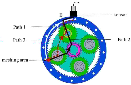
Figure 1.
Signal transfer paths in planetary gearbox.
Comparing with path 1, path 2 and path 3 are relatively longer, in addition, more parts and components are involved during signal transferring. Considering meshing clearance, damping and other influence factors, signal attenuation caused by path 2 and path 3 will be much heavier. What’s more, as vibration signal will pass through other meshing areas, signal intensity of which is as high as the signal source of interest, attenuated vibration signal will be overwhelmed by the meshing areas they pass through. Thus, vibration signal transferring through path 1 is more reliable than others, and should be mainly considered.
Shown in Figure 2 is how the dominate signal transfer path changes in a carrier cycle as planetary gearbox runs.
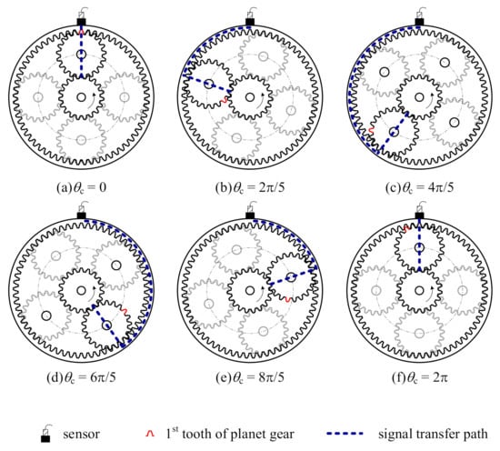
Figure 2.
Signal transfer path in a carrier cycle.
When planet gear and ring gear meshes at the sensor, as shown in Figure 2a, signal transferring path is shortest, and there will be no signal attenuation. On the contrast, when planet gear and ring gear meshes at the radial opposite position of sensor, signal transferring path is longest, and there will be the severest signal attenuation. Dynamically, as planet-ring gear meshing area departs from the sensor, which is shown in Figure 2a–c, signal transferring path will become longer and longer until planet gear and ring gear meshes at the radial opposite position of sensor. As a result, vibration signal caught by sensor will be weaker. As planet-ring gear meshing area draws near to the sensor, which is shown in Figure 2d–f, signal transferring path will become shorter and shorter until planet gear and ring gear meshes at the sensor, vibration signal caught by sensor will be stronger as well. Variation period of signal transferring path is identical with rotating period of carrier.
Unique planetary movement in planetary gearbox brings in difficulties to research on signal modeling and fault diagnosis method; Inalpolat [5,37] and Feng [11] proposed a Hanning function-based model to describe the transmission path; Liang [38] improved this model by reconsidering the influence of planet gear when it is in the farthest location. Figure 3a shows the Hanning function-based model of signal transfer path.
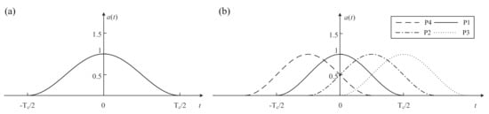
Figure 3.
Hanning function-based signal transfer path: (a) Hanning function based model of signal transfer path; (b) Modulation effect of a four-planet-gear planetary gearbox.
In terms of modulation effect, various demodulation algorithms including Hilbert transform [39,40] and TKEO (Teager–Kaiser energy operator) [41,42] can be used to overcome it. However, modulation in planetary gearbox is multiple overlapping modulations because of that multiple gear meshing exist simultaneously within a planetary gearbox. Modulation effects of a four-planet-gear planetary gearbox is shown in Figure 3b. It can be noticed that signal transfer paths caused modulation functions overlap with each other. In this way, traditional demodulations method are not good choices anymore. An interesting phenomenon in Figure 3b is that, when the planet gear meshes at the sensor, taking P1 at t = 0, e.g., vibration signal of P1 meshing will be stronger than that of others in the sensor captured signal. This may be helpful to overcome the unique modulation effect by extracting data segments when a planet gear meshes at the sensor.
2.2. Dynamic Model of Planetary Gear
Dynamic model of planetary gear is shown in Figure 4a, some important parameters are given as well. For different dynamic components, dynamic parameters are distinguished according to the initial letter of their names. Specifically, c presents carrier, r presents ring gear, s presents sun gear, and p presents planet gear. When it is necessary to refer to a planet gear, subscript like n = 1, 2,…, NP will be used, and NP is planet gear number.
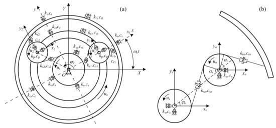
Figure 4.
Planetary gearbox: (a) dynamic model and (b) relative displacement.
For convenience to describe motion of each dynamic gear components, several coordinates are used, which is shown in Figure 4a. Coordinate OXY is fixed to the earth, it is static all the time. Coordinate Oxy is fixed to the carrier, in other words, Oxy rotates with the carrier, its rotating speed is exactly same with the carrier, and the x axis of Oxy overlaps with first planet gear center. Coordinate Onxnyn is also rotating coordinate, its origin is located at the center of planet gear Pn.
Physical meaning of dynamic parameters in Figure 4 is explained as follows:
- xi, yi (i = s, r, c, 1, 2, …, NP). Translational displacement of gear components, which are evaluated in Oxy.
- ui (i = s, r, c, 1, 2, …, NP). Rotational displacement of gear component, also evaluated in Oxy. ui = riθi, where ri is radius of base circle for gear components or center circle of carrier, θi is angular displacement.
- φn (n = 1, 2,…, NP). Phase difference between OOn and x axis of Oxy, φn = 2π (n − 1)/NP.
- kp, cp. Planet gear bearing stiffness and damping.
- ki, ci (i = c, r, s). Radial stiffness and damping of carrier, ring gear, and sun gear.
- kit, cit (i = c, r, s). Tangential stiffness and damping of carrier, ring gear, and sun gear.
Relative displacement analysis of planetary gearbox is shown in Figure 4b, and following is the detailed analysis of relative displacement between sun and planet gear. Relative displacement of other meshing pair can be derived in the same way.
Defining the positive direction as pointing from sun gear to planet gear along the meshing line, by projecting sun gear displacement and planet gear displacement to the meshing line, the relative displacement between sun gear and planet gear can be derived as the following:
xs and ys are translational displacements of sun gear in x direction and y direction, their projections are -xssinφsn and yscosφsn, where φsn = φn − αs; xn and yn are translational displacements of planet gear in x direction and y direction, respectively, and their projections are -xnsinφsn and yncosφsn; us and un are rotational displacements of sun gear and planet gear, respectively, and their projections are us and un, respectively. Assuming the meshing error between sun and planet gear is esn, accordingly, the relative displacement can be derived as
Similarly, relative displacement between ring gear and planet gear is
Relative displacements between carrier and planet gear are
Usually, sun gear works as the input gear in a planetary gearbox while the carrier works as the output component in a speed-decreasing gearbox. Input and output components are reversed in a speed-increasing gearbox. Assuming the torque on sun gear and carrier are Ts and Tc, respectively, mass of each component is mc, mr, ms, and mp and moment of inertia is Ic, Ir, Is, and Ip. According to Newton’s second law, dynamic functions can be written as the following:
Dynamic functions of carrier are
dynamic functions of ring gear are
dynamic functions of sun gear are
and dynamic functions of planet gear n are
where ksn and krn are TVMS (time-varying meshing stiffness) of sun-planet meshing and ring-planet meshing and δsn, δrn, δcnx, δcny, and δcnu are relative displacements.
Taking advantage of the dynamic model, dynamic responses under health and fault condition could be simulated. Simulation signal can also be used to validate fault diagnosis method of planetary gearbox.
2.3. Ring-Planet and Sun-Planet Meshing Stiffness under Health and Fault Condition
Among all parameters in dynamic model of planetary gearbox, meshing stiffness is of great importance [43]. Meshing stiffness is time-varying since gear meshing pair shifts between single-tooth meshing and double-tooth meshing periodically when planetary gear box runs.
In terms of planet gear, it meshes with ring gear and sun gear simultaneously. When planet gear is damaged, both ring-planet and sun-planet meshing stiffness will deviate from their normal curve. Shown in Figure 5 is meshing stiffness of ring-planet and sun-planet meshing under health and fault condition.
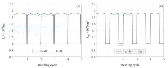
Figure 5.
Meshing stiffness under health and fault condition: (a) ring-planet meshing and (b) sun-planet meshing.
In Figure 5, under health condition, the meshing stiffness of meshing pairs vary periodically. When the planet gear meshes with ring gear or sun gear during single-tooth meshing period, meshing stiffness is smaller. When the planet gear meshes during double-tooth meshing period, meshing stiffness is larger. Duty cycle of double-tooth meshing depends on contact ratio of meshing pair.
Under health condition, meshing stiffness of ring-planet meshing in each meshing cycle is identical since gear teeth are identical, as well as sun-planet meshing stiffness. When a planet gear tooth is damaged, the meshing stiffness will be smaller since the damaged gear tooth is weaker than a normal one. As shown in Figure 5a, when planet gear tooth is damaged, meshing stiffness is smaller than health condition if the damaged planet gear tooth meshes with ring gear. On the contrast, the ring-planet meshing stiffness becomes normal when the damaged planet gear tooth meshes out. The same situation could be found in Figure 5b as well.
As a result, overall dynamic responses of the planetary gearbox will be influenced by planet gear fault since meshing stiffness changes when damaged planet gear tooth engages in meshing with ring gear or sun gear.
Paradigm of planet gear fault diagnosis is detecting fault features of planet gear from the overall dynamic responses (usually vibration signals) by various signal processing techniques. Theoretical understanding of characteristics of overall responses helps developing fault diagnosis method.
Shown in Figure 6 is simulation signals of planetary gear under health condition and fault condition. The simulation parameters are listed in Table 1.
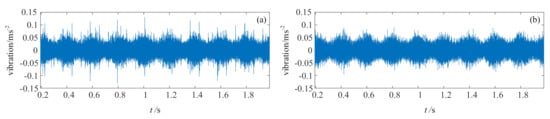
Figure 6.
Dynamic simulation signal: (a) fault condition and (b) health condition.

Table 1.
Dynamic simulation parameters.
During the simulation, rotating frequency of the carrier is 5 Hz, which means the period of carrier rotation is 0.2 s. From Figure 6, we can see the vibration signal amplitude varies when the gearbox runs. Its period is 0.2 s as well, which indicates that the vibration signal is modulated by the planetary movements.
The dynamic simulation signal reveals that:
- (1)
- under health condition, planetary gearbox generates vibrations since meshing stiffness is time varying.
- (2)
- damage on planet gear mainly influences meshing stiffness when planet gear meshes with ring gear or sun gear.
- (3)
- planetary gearbox vibration signal is modulated by the planetary movements.
- (4)
- vibration signal under fault condition contains more impulsive signal components that are caused by the damage on planet gear, but the regular vibrations are still significant and dominant.
3. Fault Diagnosis Method of Planet Gear Based on CVS and MED
Analysis in Section 2 indicates that challenges of planet gear fault diagnosis mainly include planetary movements-caused modulation effects and regular vibrations-caused signal overwhelming for fault-induced impulsive signals. To address these challenges while overcoming shortage of vibration separation, continuous vibration separation (CVS) for planet gear is proposed after meshing regularity analysis, then minimum entropy deconvolution (MED) filter method is used for enhancement detection of fault-induced impulses, and at last, a fault diagnosis method of planet gear using CVS and MED is proposed.
3.1. Meshing Regularity of Planet Gear Tooth
As shown in Figure 2, planet gear of interests passes the sensor once in a carrier cycle. According to analysis in Section 2.1, when the planet gear meshes with ring gear at the sensor position, sensor captured signals will be dominated by the very planet meshing. Additionally, signal of the planet gear is less influenced by planetary movements-caused modulation effects at the time. If we extract a segment of signal from the monitoring signal that corresponds to the moment when the planet gear meshes at the sensor position, the extracted signal segment mainly contains dynamic responses of the planet gear that meshes at the sensor, moreover, the extracted signal is less influenced by the modulation effect.
When the planet gear meshes at the sensor again after a carrier cycle, the tooth aligns with the sensor will be different. Comparing Figure 2a,f, the 1st tooth of the planet gear aligns with the sensor when θc = 0 while does not aligns with the sensor when θc = 2π. It can be easily concluded that planet gear tooth number aligns with the sensor changes periodically as planetary gearbox runs, but the detailed meshing regularity should be investigated in order to build mapping relationship between extracted signal segments and planet gear teeth.
Without losing generality, assuming planet gear tooth of Pn that aligns with the sensor in k-th carrier cycle will be , accordingly, after a full carrier cycle, when planet gear meshes at the sensor again, planet gear will mesh with ring gear Nr times. The planet gear tooth that aligns with the sensor will be
where
where mod(x, y) is modulo function. Equation (8) is a recurrence formula, it is equivalent to the following equation
Equation (10) reveals how planet gear tooth number, which aligns with the sensor, changes as planetary gearbox runs. Tooth number is neither monotone increasing from 1 to Np nor monotone deceasing from Np to 1, but it changes as addition of modulo Np. Accordingly, period of tooth number can be derived as well. The period is equal to Planet Gear Hunting Tooth Ratio (PHTR). PHTR is the minimum rotation of carrier to reset the planet gear to its initial state [44].
where LCM(x, y) is the least common multiple of x and y. All planet gear will be reset to its own initial condition when one of them is reset to initial condition since movements of planet gears are identical in a planetary gearbox during operation.
is an important parameter in Equation (10) since tooth numbers in following carrier cycles are evaluated based on it. However, it is difficult to define first tooth of planet gear since planet gear has rotational symmetric. In Refs. [31,32], first tooth of planet gear is defined as the gear tooth that meshes with ring gear under initial condition. In this way, gear tooth number that meshes at the sensor in first carrier cycle is evaluated according to the initial phase differences ψn (n = 1, 2, …, NP) between planet gear and sensor by the following equation
Given initial phase difference, tooth number of ring gear and planet gear, tooth index of planet gears in each carrier cycle could be evaluated accordingly. For example, a planetary gear that contains 4 planet gears, its ring gear tooth number is 96, sun gear number is 28, and planet gear number is 34. Assuming initial phase differences between planet gears and sensor are 0.51, 2.08, 3.65, and 5.22 radians, respectively, Tooth Index of planet gears will be 8, 32, 22, and 12 in the first carrier cycle. Tooth Index of planet gears is listed in Table 2.
Table 2.
Tooth Index of planet gears.
It is noticeable that Tooth Index of planet gears in first carrier cycle and eighteenth carrier cycle is identical. Table 2 suggests a period of 17 carrier cycles, which equals to PHTR = LCM (96, 34)/96 = 17 according to Equation (11).
3.2. Continuous Vibration Separation for Planet Gear
Vibration separation technique is a signal processing algorithm to separate dynamic responses of each gear using an extracting and mapping strategy. It takes advantage of the modulation effect to extract a segment of signal for each planet gear when planet gear meshes at the sensor and mapping the signal segments back to normal tooth number order according to mapping index.
There are 3 stages in VS: acquisition/interpolation, extraction, and assembly. The acquisition/interpolation stage encompasses the synchronously collected vibration data and tachometer data, divides vibration data into each shaft cycle according to the tachometer data, and then interpolates data after filtering. Extraction stage extracts a predetermined number of data points from every shaft cycle according to extraction index, which presents the moment when planet gear is aligned with the vibration sensor. The extracted data are stored in a structured matrix called the assembly family. Assembly stage recovers dynamic responses of each gear component by assigning a mapping index to the extracted data in assembly family. The mapping index depends on the planet gear tooth engaged in meshing at the time when the data are extracted. Similar to TSA, the dynamic responses recovered using VS covers a full cycle of planet gear. Detailed and step by step procedure can be found in Refs. [31,32,33].
Since result of VS contains only one cycle of dynamic responses of the planet gear, fault-induced impulses, if exists, will appear only once in the resultant signal of VS, which brings in inconvenience for further signal processing and fault detection. To address this problem, a continuous vibration separation method is proposed to separate dynamic responses of planet gear while keeping signal periodicity.
Figure 7 shows procedure of CVS where similar to VS, 3 stages (namely, acquisition and resampling, extraction, and MCT (mapping, combining, and TSMA)) are included in CVS.
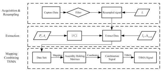
Figure 7.
Procedure of continuous vibration separation (CVS).
In first stage, vibration signal is resampled to eliminate speed fluctuations after filtering. The vibration signal must be collected with tachometer signal synchronously. Additionally, resampling rate L should be an integer multiple of ring gear tooth number for data extraction and mapping in the following stages.
Second stage of CVS is data extraction. A series of window functions are used to extract data segments that are less modulated by the planetary movements from the resampled signal. Two parameters should be deliberated, namely, window center and window width. In terms of window center, several alternative approaches were given in Refs. [13,33,35]. In terms of window width, a large window width is not suitable since modulated signals will be extracted, but it must be wide enough to cover all planet gear teeth. In Table 2, half of the planet gear tooth aligns with the sensor while the other half does not. The window width should be larger than Np/PHTR.
Last stage of CVS mainly consists of mapping, combining, and TSMA (MCT). Detailed process of MCT can be found in Ref. [23]. MCT rebuilds dynamic responses of planet gears by mapping the extracted data segments to Assembly Holding Matrix (AHM), then combination signal is constructed by lining up signals rebuilt from each AHM, and after that, TSMA is applied to combination to depress noises and asynchronous signal components within combination signal, which helps highlight fault-related signals.
Detailly, for a given planet gear, a segment of signal could be obtained by data extraction in every carrier cycle. Assuming the carrier rotates N times when collecting data, N data segments will be extracted. Since planet gear will reset to its initial state every PHTR carrier cycles, dynamic responses of planet gear could be rebuilt from consistent PHTR data segments. In this way, the extracted data segments are divided into Nset groups every PHTR cycles, where Nset = floor (N/PHTR). Then, a mapping procedure could be conducted according to the meshing regularities of planet gear, as a result, one cycle of planet gear’s dynamic response could be rebuilt from the AHM. By lining up the dynamic responses of each cycle, we can get the combination signal, and the combination signal covers Nset cycles of planet gear, instead of only one cycle in VS. At last, TSMA [45] (Time Synchronous Moving Average) algorithm is used to filter out noises and asynchronous signals while keeping signal periodicity.
The first 2 stages of CVS are same with that of VS. CVS is an improvement of VS in order to keep signal periodicity while overcoming modulation effects using a new mapping and averaging approach. Result of CVS for planet gear will be dynamic signals of each planet gear, which covers more than one cycle of planet gear cycle. Comparing with VS, the signal periodicity may help further signal processing and feature extraction.
3.3. Minimum Entropy Deconvolution Filter
Besides modulation effects caused by planetary movements, fault-related impulses detection under noises is a challenge for fault diagnosis of planet gear. Fault-related impulses are transient signal that decays quickly, and they only exist when the faulted gear tooth meshes with other gear. Moreover, they could be easily polluted by regular vibrations and noises as well. In this paper, MED is used for enhancement detection of fault-related impulses.
TSMA signal x mainly consists of three parts. The most dominate one is regular vibrations u, fault-induced impulses d will be introduced when gear tooth is damaged, and noises n is inevitable. Effects of signal transferring path can be modeled as h. As shown in Figure 8, TSMA signal can be written as
where * is convolution operator, and
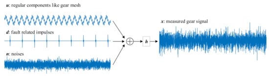
Figure 8.
Gear signal components.
MED [46] is a filtering method that aimed to minimize the entropy of the signal. In other words, the filter could maximize the impulsiveness (kurtosis) of the signal. MED is a kind of blind deconvolution since it recovers the impulsive signal from the input signal without knowing system parameters [47] or other prior information. In terms of planet gear fault-related impulse enhancement, the fault-related impulses are signals that needs to be recovered from TSMA signal.
Assuming the MED filter is f with a length of E
Applying the filter to gear signal x, the output will be
A practical approach to solve the optimized filter can be written as [48]
where
3.4. Fault Diagnosis Method for Planet Gear Using CVS and MED
The fault diagnosis method of planet gear based on CVS and MED is shown in Figure 9.
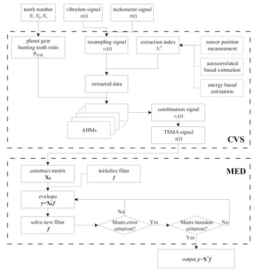
Figure 9.
Fault diagnosis method for planet gear.
The method takes tooth number, vibration signal, and tachometer signal as inputs, while dynamic responses of planet gears are the outputs. As stated above, two problems should be addressed to diagnose planet gear fault effectively, namely, planetary movements-caused modulation effects and regular vibrations-caused signal overwhelming for fault-induced impulsive signals. In the whole signal processing procedure of the proposed method, CVS algorithm is used to extract dynamic responses of planet gear and MED is used for enhancement detection of the fault-induced impulses when damage occurs on planet gear. During CVS, a moving average filter similar to TSA, which is named “TSMA,” is used to depress noises and asynchronous signal components. To help better understanding of the algorithm details, the flow diagram of the method is given in Figure 9 as much as possible.
4. Method Validations Using Simulations and Experiments
To validate effectiveness of the planet gear fault diagnosis method proposed in this paper, simulation signals were generated and processed. Fault-seeded experiment and baseline experiment under health condition were conducted to collect signals for analysis as well. The proposed method is compared with VS to illustrate its advantages.
4.1. Simulation Signal Analysis
Health and planet fault simulation signals were generated using the dynamic model described in Section 2. Planetary gearboxes under health condition and planet gear fault condition were simulated respectively. During the simulation, initial phase differences between planet gears and sensor were 0.51, 2.08, 3.65, and 5.22 radians, rotating frequency of the carrier is 10 Hz, and simulation duration is 20 s to generate sufficient simulation for analysis. Other parameters that used during simulation are same as those in Table 1. Shown in Figure 10 are vibration signal and tachometer signal (tachometer is located at the carrier). Because of heavy noises, it is hard to observe modulation effect caused by planetary movements directly in Figure 10. The SNR (signal noise ratio) of the simulation signal is −6 dB.
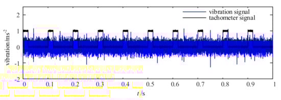
Figure 10.
Simulation signal waveform (vibration and tachometer).
According to fc and fs, there are 2560 data points in each carrier cycle. To make sure that data points collected during a cycle is an integer multiple of ring gear tooth number, a resampling rate of 2592 is used during angular resampling, which helps minimize the interpolation error since 2592 is the nearest multiple of Nr to 2560. Thus, DPT (data per tooth) equals to 27. Correspondingly, extraction index in each cycle are 210, 858, 1506, and 2154 according to
where Δθ = 2π/L, which equals to 0.0024 radians. L is the resampling rate.
During data extraction, a window width of 2 gear tooth is used since Np = 34 while PHTR = 17. Such a window ensures that extracted data covers all planet gear teeth while avoiding data segments overlapping. Thus, 2 × DPT = 54 data points are extracted at every extraction index. Figure 11 shows how data are extracted and labeled with planet gear numbers.
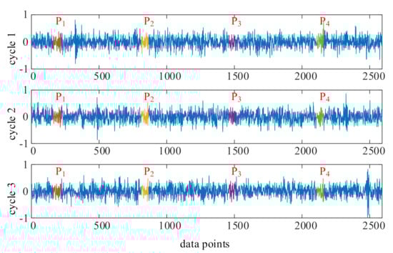
Figure 11.
Data extraction in cycle 1~3.
Hunting tooth ratio of planet PTHR = 17, which means at every 17 carrier cycles, extracted data will correspond to same gear tooth. In this case, 200 cycles data are generated, correspondingly, 200 data pieces are extracted; thus, 11 Sets can be obtained by dividing every 17 data pieces into a group, and last 13 data pieces are ignored since signal of a full planet gear cycle cannot be obtained from them.
The next step is data mapping. In this step, planet gear meshing regularity is used to guarantee that data segments are mapped to the corresponding location in AHM. AHM is a matrix that has DPT × Np rows and PHTR columns, and in each column, data piece extracted is mapped to corresponding position with help of tooth index. Taking planet gear P1, e.g., the planet gear tooth that meshes at the sensor in first carrier cycle is 8, which is shown in Table 2. Accordingly, the first data segments in each group should be mapped to tooth 8 in AHM. In second carrier cycle, the planet gear tooth that meshes at the sensor is 2; thus, the second data segments should be mapped to tooth 2 in AHM. Shown in Figure 12 is an AHM of P1. Data segments are mapped to their corresponding gear tooth number. Summing of the AHM will be planet gear dynamic responses in a planet gear cycle, which is shown as black waveform at the right side of the AHM in Figure 12.
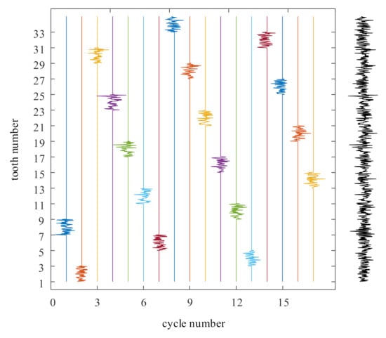
Figure 12.
An example of Assembly Holding Matrix (AHM).
By lining up rebuilt dynamic responses, combination signal can be obtained. Dynamic responses of planet gear P1 can be obtained after applying TSMA algorithm. Lastly, MED filter is used for enhancement detection of fault-induced periodic impulses within the CVS signal.
Shown in Figure 13 is raw simulation signal and its envelope order spectrum. Envelope spectrum is a widely used impulse period detection method, and it has long been proven effective in fault diagnosis studies. For better comparison, frequency axis of spectrum is normalized using planet gear fault character frequency. Shown in Figure 13a is raw simulation signal waveform in first 11 carrier cycles. No apparent fault symptoms can be observed because of existence of heavy noise. The envelope order spectrum suggests that planet gear is damaged. However, the amplitude at the fault characteristic orders is not significant.
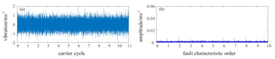
Figure 13.
Raw simulation signal: (a) signal waveform; (b) envelope order spectrum.
Shown in Figure 14 is CVS signal and its envelope order spectrum. Comparing time domain waveform of raw signal and CVS signal, noises within the signal are effectively depressed. Additionally, periodical impulses can be observed in CVS signal though not very significant. The envelope spectrum shown in Figure 14b indicates that the periodical impulses are fault-related impulses. Amplitude peaks at planet gear fault characteristic order and its multiples are more significant than that in raw signal envelope spectrum.

Figure 14.
CVS signal: (a) signal waveform; (b) envelope order spectrum.
Shown in Figure 15 is MED signal and its envelope order spectrum. Signal waveform in Figure 15a has more dominant impulses than CVS signal. Here, 11 equally spaced periodic impulses can be easily observed since MED enhances the impulsive signals using a maximum kurtosis criterion. In Figure 15b, amplitude peaks at planet gear fault characteristic order are more significant.
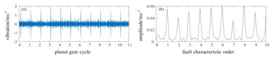
Figure 15.
MED signal: (a) signal waveform; (b) envelope order spectrum.
4.2. Experiment Signal Analysis
To verify effectiveness of the proposed method practically, experiments were conducted to collect signals under planet fault condition, as well as health condition.
Laboratory experiments were conducted on a planetary gearbox test rig. Figure 16a,b shows its mechanical schematic. The test rig mainly includes driving motor, bevel stage, first and second planetary stage, speed-up gearbox, and load motor. Experiments can be carried out on bevel stage and two planetary stage to explore fault mechanism and response of gears; speed-up gearbox is used to match running speed and torque between driving motor and load motor. Parameters of test rig are listed in Table 3.
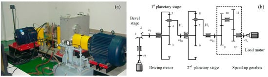
Figure 16.
Planetary gearbox test rig: (a) test rig image; (b) test rig schematic diagram.
Table 3.
Parameters of test rig.
Fault-seeded and baseline experiments were conducted on the test rig, a broken plane gear is used to simulate planet gear damage on second planetary stage. The damaged planet gear is shown in Figure 17. Piece of planet gear tooth was cut off to imitate planet gear fault using wire-electrode cutting machine.
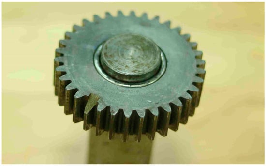
Figure 17.
Planet gear with tooth broken fault.
Figure 18 shows the vibration sensors that were used to collect vibration signals during the test. Two sensors were installed on each planetary stage in vertical and horizontal direction, respectively. Sampling rate is 5.12 kHz. Signal collected in the vertical direction is used for further analysis; the sensor is highlighted with a red circle in Figure 18. Tachometer is located at the carrier shaft to collect once-per-revolution tachometer signal.
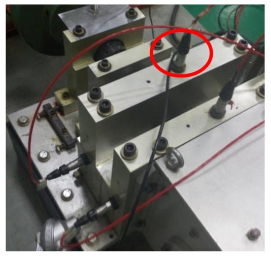
Figure 18.
Vibration sensors installed on test rig.
During the experiments, driving motor running speed was 1200 r/min and torque is 41.2 Nm. Accordingly, rotating speed of second stage planet carrier was 30.10 r/min. For that, 198.4 s data were collected during each test. Shown in Figure 19 is vibration and tachometer signal from 4 to 20 s collected during a test.
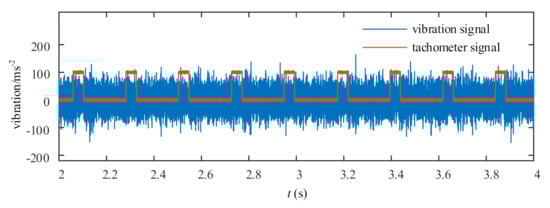
Figure 19.
Laboratory experiment signal.
Data manipulating process has been described step by step in detail when processing simulation signals. Demonstration of how signal changes after each step will not be covered in this section. We focus on comparison of signals under fault condition and health condition to validate effectiveness on fault diagnosis of planet gear, and then, VS method is used to process experimental data for a comparative study. DPT was set as 50 when resampling and processing experimental signals.
Figure 20 shows raw experimental signal and its envelope order spectrum. The waveform of raw signal under health and fault condition tells no apparent difference caused by planet gear fault since heavy noise exists within the signal. The envelope order spectrum reveals that amplitudes at fault characteristic order and its multiples increases. However, the fault feature is very weak. Additionally, other frequency components interfere diagnosis of planet gear fault.
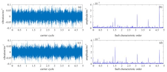
Figure 20.
Raw signal: (a) health condition waveform, (b) health condition envelope order spectrum, (c) fault condition waveform, and (d) fault condition envelope order spectrum.
Figure 21 shows the resultant signal using the proposed CVS-MED method. The collected data covers 97 full carrier cycles, and the PHTR is 17. As a result, MED signal covers 5 cycles of planet gear. Comparing with raw signal, the noises within the raw signal is effectively depressed, and unrelated frequencies are filtered out by TSMA filtering. Comparing Figure 21a,c, namely, CVS-MED signal under health and fault condition, five equally spaced impulses emerge in the CVS-MED signal when planet gear is under fault condition. The fault-induced impulses are stronger than other impulses within the signal. Moreover, amplitudes at fault characteristic order and its multiples increases significantly, which highly suggests the occurrence of planet gear fault. After processing, using the proposed CVS-MED method, planet gear fault could be diagnosed much more easily. The experimental signal processing result indicates that the CVS-MED-based method is effective to diagnose planet gear fault.
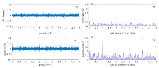
Figure 21.
CVS-MED signal: (a) health condition waveform, (b) health condition envelope order spectrum, (c) fault condition waveform, and (d) fault condition envelope order spectrum.
For comparative study purpose, experimental signals are also processed using VS. Shown in Figure 22 is VS signal, as well as its envelope order spectrum. Comparing VS signal and raw signal, the noises within raw signal is effectively depressed. Comparing VS signal waveform with and without planet gear fault, it can be easily observed that VS signal with planet gear fault is more impulsive than health condition. A strong impulse is introduced in VS signal when planet gear is faulted. However, since VS signal is not periodic, the fault symptom could not be detected by envelope order spectrum. Energy of the fault-induced impulse spreads along the whole frequency axis instead of concentrating on fault characteristic orders.
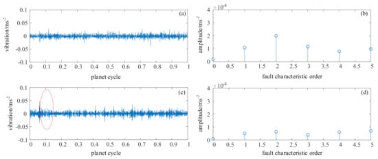
Figure 22.
Vibration separation method (VS) signal: (a) health condition waveform, (b) health condition envelope order spectrum, (c) fault condition waveform, and (d) fault condition envelope order spectrum.
The comparative study between proposed CVS-MED method and VS indicates that both CVS-MED-based method and VS are effective to detect planet gear fault when damage occurs on planet gear. However, the fault-induced impulse appears only once in VS signal since it contains only one cycle of dynamic responses of planet gear. In CVS-MED signal, the fault-induced impulse appears periodically, which helps to detect planet gear fault more easily. CVS improves the VS by keeping signal periodicity while overcoming modulation effect and depressing noises.
In summary, experimental signal analysis indicates that planet gear fault diagnosis method based on CVS and MED is effective to detect planet gear fault under heavy noises. The proposed CVS-MED method improves VS by keeping signal periodicity while overcoming modulation effect and depressing noises.
5. Conclusions
Focusing on planet gear fault in planetary gearbox, a fault diagnosis method using continuous vibration separations and minimum entropy deconvolution is proposed. Planetary movement-caused modulation effect is analyzed first. Then, a dynamic model is presented for better understanding of planet gear fault responses, as well as TVMS. The CVS-MED-based fault diagnosis method is developed after elaborating on continuous vibration separation and minimum entropy deconvolution. To validate the effectiveness of the CVS-MED-based method, both simulations and fault-seeded experiments are carried out to collect signals for analysis. The proposed method is also compared with VS. Both simulation and experiment analysis indicate that the proposed planet gear fault diagnosis method based on CVS and MED is effective. Comparative study indicates that CVS-MED method improves VS by keeping signal periodicity while overcoming modulation effect and depressing noises.
Author Contributions
J.S. proposed the idea of applying CVS and MED on planet gear, conducted dynamic modeling and simulation analysis, designed the experiments, and wrote the first draft of the manuscript. L.Z. developed the program to process simulation and experimental data, participated the experiments, and revised the manuscript. N.H. proposed the theoretical system of the method, critically revised the manuscript. All authors have read and agreed to the published version of the manuscript.
Funding
This work was supported by the National Natural Science Foundation of China (Grant No. 51975576, 51475463), the Defense Industrial Technology Development Program (Grant No. WDZC20195500305), and the National Key Research and Development Program of China (Grant No. 2018YFB1702401).
Acknowledgments
Thanks to Peng Luo and Jiao Hu for their support during the experiments. The authors are grateful to the editors and anonymous reviewers for their helpful comments and constructive suggestions.
Conflicts of Interest
The authors declare no conflict of interest.
Nomenclatures
| VS | Vibration separation | LCM | Least common multiple |
| CVS | Continuous vibration separation | MCT | Mapping, combination, and TSMA |
| MED | Minimum entropy deconvolution | TSMA | Time Synchronous Moving Average |
| TVMS | Time varying meshing stiffness | AHM | Assembly Holding Matrix |
| PHTR | Planet Hunting Tooth Ratio | SNR | Signal noise ratio |
| DPT | Dot per tooth | Nr | Ring gear tooth number |
| Np | Planet gear tooth number | Ns | Sun gear tooth number |
| NP | Number of planet gears |
References
- Zhou, L.; Duan, F.; Mba, D.; Wang, W.; Ojolo, S. Using frequency domain analysis techniques for diagnosis of planetary bearing defect in a CH-46E helicopter aft gearbox. Eng. Fail. Anal. 2018, 92, 71–83. [Google Scholar] [CrossRef]
- Bhardwaj, U.; Teixeira, A.P.; Soares, C.G. Reliability prediction of an offshore wind turbine gearbox. Renew. Energy 2019, 141, 693–706. [Google Scholar] [CrossRef]
- Wang, S.H.; Zhang, S.; Shi, D.H.; Sun, X.Q.; He, J.Q. Research on instantaneous optimal control of the hybrid electric vehicle with planetary gear sets. J. Braz. Soc. Mech. Sci. Eng. 2019, 41, 51. [Google Scholar] [CrossRef]
- Kong, Y.; Wang, T.; Chu, F. Meshing frequency modulation assisted empirical wavelet transform for fault diagnosis of wind turbine planetary ring gear. Renew. Energy 2019, 132, 1373–1388. [Google Scholar] [CrossRef]
- Inalpolat, M.; Kahraman, A. A theoretical and experimental investigation of modulation sidebands of planetary gear sets. J. Sound Vib. 2009, 323, 677–696. [Google Scholar] [CrossRef]
- Zghal, B.; Graja, O.; Dziedziech, K.; Chaari, F.; Jablonski, A.; Barszcz, T.; Haddar, M. A new modeling of planetary gear set to predict modulation phenomenon. Mech. Syst. Signal Process. 2019, 127, 234–261. [Google Scholar] [CrossRef]
- Zeng, Z.; Ding, K.; He, G.; Li, W. Space-time model and spectrum mechanism on vibration signal for planetary gear drive. Mech. Syst. Signal Process. 2019, 129, 164–185. [Google Scholar] [CrossRef]
- Wang, H.; Tao, Z.; Shi, L.; Kang, Z. Fault Evolution Characteristic Analysis of Planetary Gear Based on Multidimensional Nonlinear Frequency Response. J. Comput. Nonlinear Dyn. 2019, 14. [Google Scholar] [CrossRef]
- Wei, J.; Zhang, A.; Qin, D.; Lim, T.C.; Shu, R.; Lin, X.; Meng, F. A coupling dynamics analysis method for a multistage planetary gear system. Mech. Mach. Theory 2017, 110, 27–49. [Google Scholar] [CrossRef]
- Li, M.; Xie, L.; Ding, L. Load sharing analysis and reliability prediction for planetary gear train of helicopter. Mech. Mach. Theory 2017, 115, 97–113. [Google Scholar] [CrossRef]
- Feng, Z.; Zuo, M.J. Vibration signal models for fault diagnosis of planetary gearboxes. J. Sound Vib. 2012, 331, 4919–4939. [Google Scholar] [CrossRef]
- Lei, Y.; Han, D.; Lin, J.; He, Z. Planetary gearbox fault diagnosis using an adaptive stochastic resonance method. Mech. Syst. Signal Process. 2013, 38, 113–124. [Google Scholar] [CrossRef]
- Ha, J.M.; Youn, B.D.; Oh, H.; Han, B.; Jung, Y.; Park, J. Autocorrelation-based time synchronous averaging for condition monitoring of planetary gearboxes in wind turbines. Mech. Syst. Signal Process. 2016, 70–71, 161–175. [Google Scholar] [CrossRef]
- Liu, Z.; Zhao, X.; Zuo, M.J.; Xu, H. Feature selection for fault level diagnosis of planetary gearboxes. Adv. Data Anal. Classif. 2014, 8, 377–401. [Google Scholar] [CrossRef]
- Feng, Z.; Liang, M. Fault diagnosis of wind turbine planetary gearbox under nonstationary conditions via adaptive optimal kernel time–frequency analysis. Renew. Energy 2014, 66, 468–477. [Google Scholar] [CrossRef]
- Feng, Z.; Chen, X.; Liang, M.; Ma, F. Time–frequency demodulation analysis based on iterative generalized demodulation for fault diagnosis of planetary gearbox under nonstationary conditions. Mech. Syst. Signal Process. 2015, 62–63, 54–74. [Google Scholar] [CrossRef]
- Cheng, G.; Chen, X.; Li, H.; Li, P.; Liu, H. Study on planetary gear fault diagnosis based on entropy feature fusion of ensemble empirical mode decomposition. Measurement 2016, 91, 140–154. [Google Scholar] [CrossRef]
- Cheng, Z.; Hu, N.; Gao, J. An Approach to Detect Damage Quantitatively for Planetary Gear Sets Based on Physical Models. Adv. Sci. Lett. 2011, 4, 1695–1701. [Google Scholar] [CrossRef]
- Cheng, Z. A hybrid prognostics approach to estimate the residual useful life of a planetary gearbox with a local defect. J. Vibroeng. 2015, 17, 682–694. [Google Scholar]
- Feng, K.; Wang, K.; Ni, Q.; Zuo, M.J.; Wei, D. A phase angle based diagnostic scheme to planetary gear faults diagnostics under non-stationary operational conditions. J. Sound Vib. 2017, 408, 190–209. [Google Scholar] [CrossRef]
- Song, L.; Wang, H.; Chen, P. Step-by-Step Fuzzy Diagnosis Method for Equipment Based on Symptom Extraction and Trivalent Logic Fuzzy Diagnosis Theory. IEEE Trans. Fuzzy Syst. 2018, 26, 3467–3478. [Google Scholar] [CrossRef]
- Ding, F.; Tian, Z.; Zhao, F.; Xu, H. An integrated approach for wind turbine gearbox fatigue life prediction considering instantaneously varying load conditions. Renew. Energy 2018, 129, 260–270. [Google Scholar] [CrossRef]
- Zhang, L.; Hu, N. Fault diagnosis of sun gear based on continuous vibration separation and minimum entropy deconvolution. Measurement 2019, 141, 332–344. [Google Scholar] [CrossRef]
- Wang, Y.R.; Jin, Q.; Sun, G.D.; Sun, C.F. Planetary gearbox fault feature learning using conditional variational neural networks under noise environment. Knowl. Based Syst. 2019, 163, 438–449. [Google Scholar] [CrossRef]
- Ma, S.; Chu, F.; Han, Q. Deep residual learning with demodulated time-frequency features for fault diagnosis of planetary gearbox under nonstationary running conditions. Mech. Syst. Signal Process. 2019, 127, 190–201. [Google Scholar] [CrossRef]
- Han, Y.; Tang, B.; Deng, L. An enhanced convolutional neural network with enlarged receptive fields for fault diagnosis of planetary gearboxes. Comput. Ind. 2019, 107, 50–58. [Google Scholar] [CrossRef]
- Chen, H.; Hu, N.; Cheng, Z.; Zhang, L.; Zhang, Y. A deep convolutional neural network based fusion method of two-direction vibration signal data for health state identification of planetary gearboxes. Measurement 2019, 146, 268–278. [Google Scholar] [CrossRef]
- Samuel, P.D.; Pines, D.J. Vibration separation methodology for planetary gear health monitoring. In Proceedings of the Smart Structures and Materials 2000: Smart Structures and Integrated Systems, Newport Beach, CA, USA, 6–9 March 2000; pp. 250–261. [Google Scholar]
- McFadden, P. A technique for calculating the time domain averages of the vibration of the individual planet gears and the sun gear in an epicyclic gearbox. J. Sound Vib. 1991, 144, 163–172. [Google Scholar] [CrossRef]
- McFadden, P. Window functions for the calculation of the time domain averages of the vibration of the individual planet gears and sun gear in an epicyclic gearbox. J. Vib. Acoust. 1994, 116, 179–187. [Google Scholar] [CrossRef]
- Lewicki, D.G.; LaBerge, K.E.; Ehinger, R.T.; Fetty, J. Planetary gearbox fault detection using vibration separation techniques. In Proceedings of the American Helicopter Society 67th Annual Forum, Virginia Beach, VA, USA, 3–5 May 2011. [Google Scholar]
- Hood, A.; Pines, D. Sun gear fault detection on an OH-58C helicopter transmission. In Proceedings of the American Helicopter Society International Annual Forum, Virginia Beach, VA, USA, 3–5 May 2011; pp. 1664–1690. [Google Scholar]
- Hood, A.; LaBerge, K.; Lewicki, D.; Pines, D. Vibration Based Sun Gear Damage Detection. In Proceedings of the ASME 2013 Power Transmission and Gearing Conference, Portland, OR, USA, 4–7 August 2013. [Google Scholar]
- He, G.; Ding, K.; Lin, H. Gearbox coupling modulation separation method based on match pursuit and correlation filtering. Mech. Syst. Signal Process. 2016, 66–67, 597–611. [Google Scholar] [CrossRef]
- Liang, X.; Zuo, M.J.; Liu, L. A windowing and mapping strategy for gear tooth fault detection of a planetary gearbox. Mech. Syst. Signal Process. 2016, 80, 445–459. [Google Scholar] [CrossRef]
- Guo, Y.; Zhao, L.; Wu, X.; Na, J. Vibration separation technique based localized tooth fault detection of planetary gear sets: A tutorial. Mech. Syst. Signal Process. 2019, 129, 130–147. [Google Scholar] [CrossRef]
- Inalpolat, M.; Kahraman, A. A dynamic model to predict modulation sidebands of a planetary gear set having manufacturing errors. J. Sound Vib. 2010, 329, 371–393. [Google Scholar] [CrossRef]
- Liang, X.; Zuo, M.J.; Hoseini, M.R. Vibration signal modeling of a planetary gear set for tooth crack detection. Eng. Fail. Anal. 2015, 48, 185–200. [Google Scholar] [CrossRef]
- Cerrada, M.; Sánchez, R.-V.; Li, C.; Pacheco, F.; Cabrera, D.; de Oliveira, J.V.; Vásquez, R.E. A review on data-driven fault severity assessment in rolling bearings. Mech. Syst. Signal Process. 2018, 99, 169–196. [Google Scholar] [CrossRef]
- Cheng, J.; Peng, Y.; Yang, Y.; Wu, Z. Adaptive sparsest narrow-band decomposition method and its applications to rolling element bearing fault diagnosis. Mech. Syst. Signal Process. 2017, 85, 947–962. [Google Scholar] [CrossRef]
- Soltani Bozchalooi, I.; Liang, M. Teager energy operator for multi-modulation extraction and its application for gearbox fault detection. Smart Mater. Struct. 2010, 19, 075008. [Google Scholar] [CrossRef]
- Tran, V.T.; AlThobiani, F.; Ball, A. An approach to fault diagnosis of reciprocating compressor valves using Teager–Kaiser energy operator and deep belief networks. Expert Syst. Appl. 2014, 41, 4113–4122. [Google Scholar] [CrossRef]
- Cui, L.; Huang, J.; Zhai, H.; Zhang, F. Research on the meshing stiffness and vibration response of fault gears under an angle-changing crack based on the universal equation of gear profile. Mech. Mach. Theory 2016, 105, 554–567. [Google Scholar] [CrossRef]
- Lewicki, D.G.; Samuel, P.D.; Conroy, J.K.; Pines, D.J. Planetary Transmission Diagnostics; NASA/CR-2004-213068; NASA Glenn Research Center: Cleveland, OH, USA, 2004. [Google Scholar]
- Zhang, L.; Hu, N. Time Domain Synchronous Moving Average and its Application to Gear Fault Detection. IEEE Access 2019, 7, 93035–93048. [Google Scholar] [CrossRef]
- Wiggins, R.A. Minimum entropy deconvolution. Geoexploration 1978, 16, 21–35. [Google Scholar] [CrossRef]
- Jiang, R.; Chen, J.; Dong, G.; Liu, T.; Xiao, W. The weak fault diagnosis and condition monitoring of rolling element bearing using minimum entropy deconvolution and envelop spectrum. Proc. Inst. Mech. Eng. Part C J. Mech. Eng. Sci. 2012, 227, 1116–1129. [Google Scholar] [CrossRef]
- McDonald, G.L.; Zhao, Q.; Zuo, M.J. Maximum correlated Kurtosis deconvolution and application on gear tooth chip fault detection. Mech. Syst. Signal Process. 2012, 33, 237–255. [Google Scholar] [CrossRef]


Publisher’s Note: MDPI stays neutral with regard to jurisdictional claims in published maps and institutional affiliations. |
© 2020 by the authors. Licensee MDPI, Basel, Switzerland. This article is an open access article distributed under the terms and conditions of the Creative Commons Attribution (CC BY) license (http://creativecommons.org/licenses/by/4.0/).