Article

Heat Transfer Analysis in a Single Spool Gas Turbine by Using Calculated-Estimated Coefficients with the Finite Element Method

by
Geraldo Creci
1,*,
Márcio Teixeira de Mendoça
2,
João Carlos Menezes
3 and
João Roberto Barbosa
3
1
Instituto Federal de Educação, Ciência e Tecnologia de São Paulo (IFSP-BRA), Av. Major Fernando Valle, 2013, Bragança Paulista, SP 12903-000, Brazil
2
Instituto de Aeronáutica e Espaço (IAE), Pr. Marechal Eduardo Gomes, 50, São José dos Campos, SP 12228-904, Brazil
3
Instituto Tecnológico de Aeronáutica (ITA), Pr. Marechal Eduardo Gomes, 50, São José dos Campos, SP 12228-900, Brazil
*
Author to whom correspondence should be addressed.
Appl. Sci. 2020, 10(23), 8328; https://doi.org/10.3390/app10238328
Submission received: 2 November 2020 / Revised: 19 November 2020 / Accepted: 19 November 2020 / Published: 24 November 2020

Abstract

:

Featured Application

At the end of the development program, the gas turbine should be able to drive an unmanned aerial vehicle weighing a maximum of 1200 kg and generate 1.0 MW/h of electricity. The application in the civilian market of electricity generation aims to increase the financial possibilities of success of the program, where biofuel (ethanol), derived from sugar cane, will be one of the main fuels used for motor combustion.

Abstract

In this paper, a calculation procedure is presented to estimate the heat transfer coefficients of a single spool gas turbine designed to generate 5 kN of thrust. These heat transfer coefficients are the boundary conditions which govern the heat interaction between the solid parts and the working fluid in the gas turbine. However, the calculation of these heat transfer coefficients is not a trivial task, since it depends on complex fluid flow conditions. Empirical correlations and assumptions have been used to find convective heat transfer coefficients over most components, including stator vanes, rotor blades, disc faces, and disc platforms. After defining the heat transfer coefficients, the finite element method was used to determine the temperature distribution in one eighth section of the gas turbine making use of the problem cyclic symmetry. Both static and rotating assemblies have been modeled. The results allowed the prediction of the thermal expansion behavior of the whole single spool gas turbine with special attention to the safety margin of clearances. Furthermore, having the temperature distribution defined, it is possible to calculate the thermal stresses in any mechanical component. Additionally, it is possible to specify suitable metallic alloys for achieving appropriate performance in every case. The structural integrity of all components was then assured with the temperature distribution and thermal expansion behavior under knowledge. Thus, the mechanical drawings could be released to manufacturing.

1. Introduction

During the design process, the computational simulation phase is extremely important, so that no faults occur during operation, thus avoiding serious losses and accidents. The aeronautical gas turbine studied in this work has already been designed and is under development. With an approximate weight of 650 N, a maximum diameter of 0.350 m, and a maximum length of 1.50 m, that aeronautical gas turbine is capable of producing 5 kN of thrust at the rotational speed of 28,150 rpm [1,2,3,4]. Figure 1a,b illustrate the aeronautical gas turbine studied in this work on the test rig. It is composed of an air inlet duct, a five-stage axial compressor, a direct-flow annular combustion chamber, a single stage turbine disc, and an exhaustion nozzle, in a single shaft configuration. Figure 2a,b show the compressor and turbine discs and Figure 2c shows the whole rotor assembly without bearings.
Gas turbines operate under rigorous conditions of temperature and stress. High temperatures are necessary to increase thermal efficiency and reduce fuel consumption. However, high temperatures can compromise structural integrity of mechanical components by reducing the yield strength in metallic alloys and/or favoring creep. That is why it is important to calculate the temperature distribution over the main static and rotating components of a gas turbine. The determination of the temperature distribution over the gas turbine components makes it possible to select appropriate metallic alloys to withstand the rigorous operating conditions. However, in some cases there is no appropriate metallic alloy able to meet the design requirements, and a redesign process must be conducted. In order to overcome the material barrier, extensive research and development in new metallic alloys and other materials has been done. The main objective is to be able to use higher and higher temperatures at the turbine disc entry to improve overall efficiency.
Compressor and turbine discs are critical components that should be carefully analyzed. These components are under high thermal stresses and high centrifugal loads. In spite of the fact that higher temperatures are found on turbine discs, compressor discs can also be potentially dangerous. This happens because aluminum alloys, which are usually used in compressor discs, present a strong reduction in their mechanical properties with temperature increase. In high performance compressors, the last rotor stages are made of high temperature alloys in order to withstand the high thermal and structural effects. In turbine discs, the use of Inconel alloys is a choice in the great majority of cases, since Inconel alloys present superior mechanical properties at elevated temperatures.
The heat transfer analysis presented in this paper simulates the temperature distribution over the main gas turbine components. It also provides the thermal expansion behavior of the static and rotating assemblies. With the increase in temperature in the aeronautical gas turbine there will be a proportional increase in the structural demanding for both rotating and static assemblies in terms of amplitudes of vibration. Furthermore, when considering higher temperatures, damage to the main parts of the aeronautical gas turbine is accelerated as a result of more severe fluid-structure interaction. Thus, structural analyses can be performed taking into account the thermal effects predicted, which makes it possible to assure that problems generated by high temperatures like creep, thermal stresses, reduction in mechanical strength or insufficient clearances do not cause structural collapse or malfunctioning over the studied gas turbine.

Literature Review

Mazur et al. [5] analyzed the blade failure of the first 70 MW gas turbine made of Inconel 738LC. There was degradation of the coating due to the operation at high temperature, leading to crack initiation by fatigue/creep mechanisms. Sadowski and Golewski [6] studied, by the finite element method, the Inconel 713 alloy for the problem of heat transfer in gas turbines. Kim et al. [7] investigated heat transfer and thermal stresses in a gas turbine blade with 10 internal cooling passages. Numerical three-dimensional (3D) simulations were performed using the CFX and Ansys software to calculate the temperature distributions and heat transfer coefficients. Hesham et al. [8] investigated the three-dimensional heat transfer characteristics of a gas turbine blade. The numerical results presented good agreement with experimental measurements. Chen-Zhao et al. [9] studied the fluid flow and heat transfer characteristics in the pipe cable with alternating current by using commercial code COMSOL Multiphysics based on the finite element method. Bade et al. [10] used the MATLAB/Simulink numerical model of a single cylinder, mechanical spring assisted, two-stroke natural gas fueled, spark-ignited oscillating linear engine alternator to investigate the effect of combustion and heat transfer characteristics on translator dynamics and performance. Dou, Jiang, and Zhang [11] investigated the thermal flow and heat transfer by natural convection in a cavity fixed with a fin array. The computational domain consisted of both solid (copper) and fluid (air) areas. The finite volume method was used to simulate the steady flow in the domain. Jedsadaratanachai and Boonloi [12] investigated numerically the heat transfer, pressure loss, and thermal enhancement factor in the circular tube heat exchanger inserted with V-orifices. Badreddine et al. [13] focused on the development and application of a new finite volume immersed boundary method to simulate three-dimensional fluid flows and heat transfer around complex geometries that also exist in gas turbines. Devaraj, Muthuswamy, and Kandasamy [14] studied numerically natural convection heat transfer in a two-dimensional square enclosure at various angles of inclination. The calculated correlation coefficients for the entire range of Rayleigh numbers were in good agreement with other published numerical results, thus, attesting that the achieved results were satisfactory. Several areas were, thus, numerically studied; the results were compared to empirical data showing agreement and with engineering application opportunity. This encouraged the study described in this paper.

2. Convective Heat Transfer Coefficients

In this section, the correlations used to estimate the convective heat transfer coefficients are presented. The coefficients are determined largely by mathematical relations, but also by numerical approximations using reasonable concepts within maximum and minimum limits based on common sense according to the current application and similar case studies. The heat flux from hot gases to metallic surfaces can be estimated using Newton’s convective heat transfer law
q = h ( T g T w ) ,
where q is the heat flux, h is the convective heat transfer coefficient, T g is the reference gas temperature and T w is the wall temperature. For compressible flow the reference temperature is the adiabatic wall temperature T a w . The adiabatic wall temperature, defined as
T a w = T s + r ( T T T s ) ,
takes into account energy dissipation due to viscous heating. T s is the static temperature, T T is the total stagnation temperature and r is the recovery factor. The recovery factor takes into account the diffusivity of heat and momentum. If heat diffuses faster than momentum, the thermal boundary layer is thinner than the momentum boundary layer. In this case, a higher heat transfer rate is expected. The Prandtl number is used to compare the diffusivity of heat and momentum, such that the recovery factor is defined as
r = P r 1 / 2   ( for   laminar   flow )   and   r = P r 1 / 3   ( for   turbulent   flow ) .
For P r = 0.7 , r is equal to 0.83 and 0.88 respectively. In this work an average value P r = 0.85 will be assumed, regardless of the flow regime. The distribution of the heat transfer coefficient over the surface depends on the flow conditions, gas velocity and temperature distributions. Given the gas temperature distribution, the heat flux q can be computed by Fourier’s Law as a function of the thermal conductivity of the gas k g and the temperature gradient ( d T / d y ) p ,
q = k g ( d T d y ) p .
The heat transfer coefficient can be expressed in nondimensional form, which results in the Nusselt number Nu which is defined by
N u = h x k g .
The solution of the fluid mechanics governing equations, even when the boundary layer approximation is used, is very complex for compressible flows with temperature dependent fluid properties. In a preliminary study, the heat transfer coefficient may be estimated by simplified analytical and experimental correlations. The heat transfer models presented in this paper are based on these correlations for a first order approximation. In the following sections, correlations for heat transfer coefficients are presented for the flow over stator vanes and disc blades, compressor and turbine disc faces, and compressor and turbine platforms (inner wall) and casing (outer wall).

2.1. Stator Vanes and Disc Blades

In a first order approximation, the boundary layer over a stator vane or disc blade may be represented by the boundary layer over a flat plane. For a laminar flow the velocity and temperature distributions are given by the Blasius solution [15]. In this case the convective heat transfer correlation is
h ( x ) = 0.332 k g x R e x 1 / 2 P r 1 / 3 ,
where x is the longitudinal distance from the leading edge, k g is the gas thermal conductivity, R e and P r are the nondimensional Reynolds and Prandtl numbers calculated by
R e = ρ g u g x μ g   and   P r = μ g C p k g .
where ρ g is the gas density, u g is the freestream gas velocity at x , μ is the gas dynamic viscosity, and C p is the gas specific heat at constant pressure. For turbulent flow the heat transfer coefficient is given by [16].
h ( x ) = 0.0296 k g D ( R e x 0.8 P r 1 / 3 ) .
At the leading edge, the heat transfer coefficient can be estimated based on the flow over a cylindrical surface
h a = a [ 1.14 k g D ( R e D ) 1 / 2 P r 0.4 ] ,
where a is a turbulence enhancement factor, D is the leading edge diameter and R e D is the Reynolds number based on the leading edge diameter and the approaching freestream velocity. The average heat transfer coefficient over the cylindrical surface at the leading edge is given by
h a v = 0.7 h a .
The gas properties are computed as a function of temperature. In the present model the Prandtl number is assumed to be constant and equal to P r = 0.7 . The viscosity varies with temperature according to the power law [17],
μ g = μ 0 ( T g T 0 ) 0.67 ,
where the reference viscosity of air is μ 0 = 1.5 × 10 5 at the reference temperature of T 0 = 273 (K). For combustion gases the reference viscosity is μ g = 4.23 × 10 5 (kg/(m.s)) at the reference temperature of T 0 = 1100 (K). The conductivity is computed from the definition of Prandtl number and the density is calculated by the perfect gas law
k g = μ g C p P r   and   ρ g = P R T g .
Equations (6), (8), and (10) are used to estimate the heat transfer coefficient distribution over the turbine blades and vanes. The same correlations apply to compressor blades and diffuser vanes. At the leading edge, the flow is always laminar and Equations (6) and (10) are used. Close to the trailing edge, the flow is usually turbulent and Equation (8) should be used. In gas turbine blades and vanes, the laminar and turbulent regions are separated by a transition zone that has a significant length compared to the chord. On the suction surface for both blades and vanes, there is a strong adverse pressure gradient, which hastens the transition to turbulence. In the present suction surface model, it is considered that the transition region starts at 10% of the chord, considering the leading edge as the starting point. It is also considered that the transition region ends at 40% of the chord. From this point on, the flow is assumed to be turbulent. On the pressure surface, the strong favorable pressure gradient close to the leading edge forces the flow to remain laminar. On the other hand, the freestream turbulence levels from the combustion chamber and the strong concave surface curvature try to transition the flow to a turbulent regime. These opposing effects result in a long transition region over the stator vanes. The assumed model in this work considers that on the pressure surface of the stator vanes, the transition starts at 20% of the chord length, starting from the leading edge. The flow is considered fully turbulent at 90% of the chord length. On rotor blades, the flow is considered fully turbulent at 30% of the chord. On the compressor rotor blades and diffuser vanes, the flow is considered fully turbulent from the leading edge due to the strong adverse pressure gradient throughout. These are typical values for gas turbine blades and vanes.
The heat transfer coefficient on the transition region is assumed as an average between the laminar regime, l, and the turbulent regime, t, weighted by the stream wise position between transition start (ts) and transition end (te)
h ( x ) = h l ( 1 x i x t s x t e x t s ) + h t ( x i x t s x t e x t s ) .
The distribution of convective heat transfer along the vanes or blades is used to compute an integral average heat transfer coefficient at three different radial positions, base, mid span, and tip. Given that the leading edge diameter is less than 1 mm, the coefficient h l e would be an unrealistically high value. Therefore, it will not be used to evaluate the average value. The proposed model for the leading edge is only valid for thicker blades of cooled turbine blades.

2.2. Compressor and Turbine Discs

This section presents heat transfer correlations for spinning discs when they are cooled by an outward flow of cooling air and when the discs are cooled by an impingement jet at the disc rim, which is of much use. It also presents the disc heat transfer correlation to calculate the disc heat transfer coefficient without cooling flow.

2.2.1. Convective Cooling

The Nusselt number N u = h r o / k on a spinning disc may be correlated according to Evans [18] as
N u = 0.0346 ( R e r o ) 0.8 ( k v ) 0.1 ( r o r c ) 0.3 ( z r o ) 0.06 P r 0.6 ,
where r o is the disc external radius and r c is the radial position where the cooling flow is introduced.
k v = R e r o ( r o / r c ) 2 R e m ,
The mass flow Reynolds number R e m is defined as a function of the coolant volumetric flow rate Q p , with z being the disc clearance at the rim and v being the kinematic viscosity. The rotational Reynolds number R e r o is defined as a function of the angular velocity w
R e m = Q p / ( 2 π v z )   and   R e r o = w r o 2 / v .

2.2.2. Impingement Cooling

In order to increase the heat removal and avoid overheating, it is possible to use impingement cooling at the disc rim. Disc cooling by impingement is usually done on the first turbine stage where the temperatures are higher. Typical cooling parameters can be used to obtain an order of magnitude for the convective heat transfer coefficient. Thus, it is possible to compare the temperature distribution obtained by impingement cooling and convection cooling. Then, the most appropriated method may be selected. The correlation proposed by Evans [18] is
N u ¯ = 1 2 K θ K 90 R e D m P r 1 / 3 ( Z n D ) 0.0091 ,
1 = 3.48 / ( X n / D ) 2.79 ,   2 = 1 / [ 1 + 0.459 ( Z n / D ) ]   and   m = 0.538 ( X n / D ) 0.237 ,
where N u is the average impingement jet average Nusselt number, 1 , 2 , and m are correlation coefficients, K θ / K 90 is the impingement angle coefficient, R e D is the impingement hole Reynolds number, P r is the Prandtl number, Z n is the impingement hole to disc spacing, X n is the circumferential spacing between holes, and D is the hole diameter. Typical values are used to estimate the heat transfer coefficient: X n / D = 7.5 , Z n / D = 1.9 , K θ / K 90 = 1 (normal impingement), R e D = 1 × 10 4 and D = 0.2 (mm). The average convection heat transfer coefficient is given by
h ¯ = N u ¯ k / D .

2.2.3. Heat Transfer Coefficient without Cooling Flow

The model of a spinning disc in an infinite medium is used for the rear turbine disc face, according to Evans [18]
N u = 0.0198 ( R e r o ) 0.8 P r   and   h = N u ( k g / r o ) .

2.3. Turbine Annular Passage: Inner and Outer Walls

At the top of the disc, or disc platform, the Nusselt number may be estimated based on correlations of flow in a channel. The correlations of flow in a channel are also valid for the stators and diffuser inner and outer walls. The average Nusselt number is given by the correlation proposed by Evans [18]
N u = h D p k g = 0.021 ( R e p ) 0.8 ( P r ) 0.6 ,
where D p is the hydraulic diameter of the blade to blade passage, h is the average heat transfer coefficient, and k g is the conductivity of the combustion gases. The Reynolds number is given by the mass flow G and by the hydraulic diameter
R e p = ( D p G ) / μ g   and   D p = ( 2 y m S h u b ) / ( y m + S h u b ) .
y m is the average blade height and S h u b is the blade pitch at disc platform. The mass flux G = ρ V a v is given by the gas density times the mean velocity vector computed as a function of the inlet β 1 and exit β 2 flow angles. Relative quantities are used when computing the properties of the discs
V a v = V a a v / ( cos β a v ) ,   V a v = 0.5 ( V a i + V a e )   and   tan β a v = 0.5 ( tan β 2 tan β 1 ) .
where V a i and V a e are the inlet and exit axial velocities. The heat transfer coefficient is given by
h = k g N u / D p .
At the disc annular passage outer surface, a similar approach could be used, but it would not take into account the leakage flow at the blade tip. Usually the heat transfer coefficient on this region is the same order of magnitude of the coefficient at blade tip. Therefore, at the disc annular passage outer surface, the same heat transfer coefficient at the blade tip presented in Section 2.2 is used.

2.4. Heat Transfer on the Combustor Annular Passage

The heat load to estimate the temperature distribution on the combustor is computed according to [19]. Radiation and convection from the combustion gases are in equilibrium with the radiation to the engine casing and convection to the air flow on the annular passage between combustor wall and casing. The radiation takes into account the combustion gases temperature and the gas emissivity. The convection on the annular passage inside the combustor and on the combustor/casing annular passage is computed according to the correlation [19]:
h a n = 0.02 ( k a i r N u D a n 0.2 ) ( m ˙ a i r A a n μ a i r ) 0.8 ,
D a n = 2 H a n   and   A a n = π 4 ( D e x 2 D i n 2 ) ,
where, h a n is the convection heat transfer coefficient, k a i r and μ a i r are the conductivity and viscosity of the air, D a n is the hydraulic diameter of the annular passage, m ˙ a i r is the air mass flow rate and A a n is the area of the annular passage. D e x and D i n are the external and internal annular passage diameters. H a n is the annulus height.

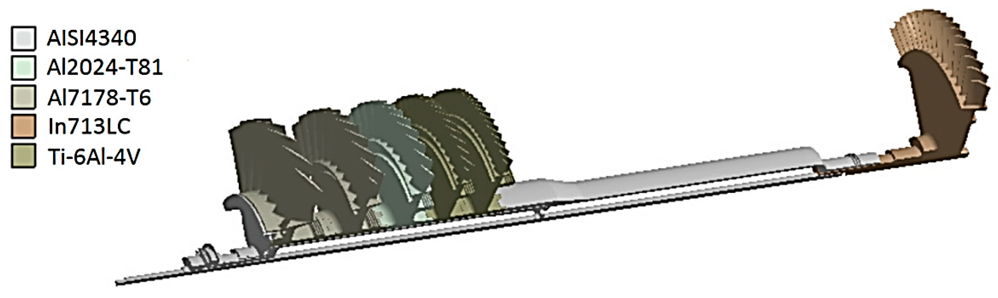
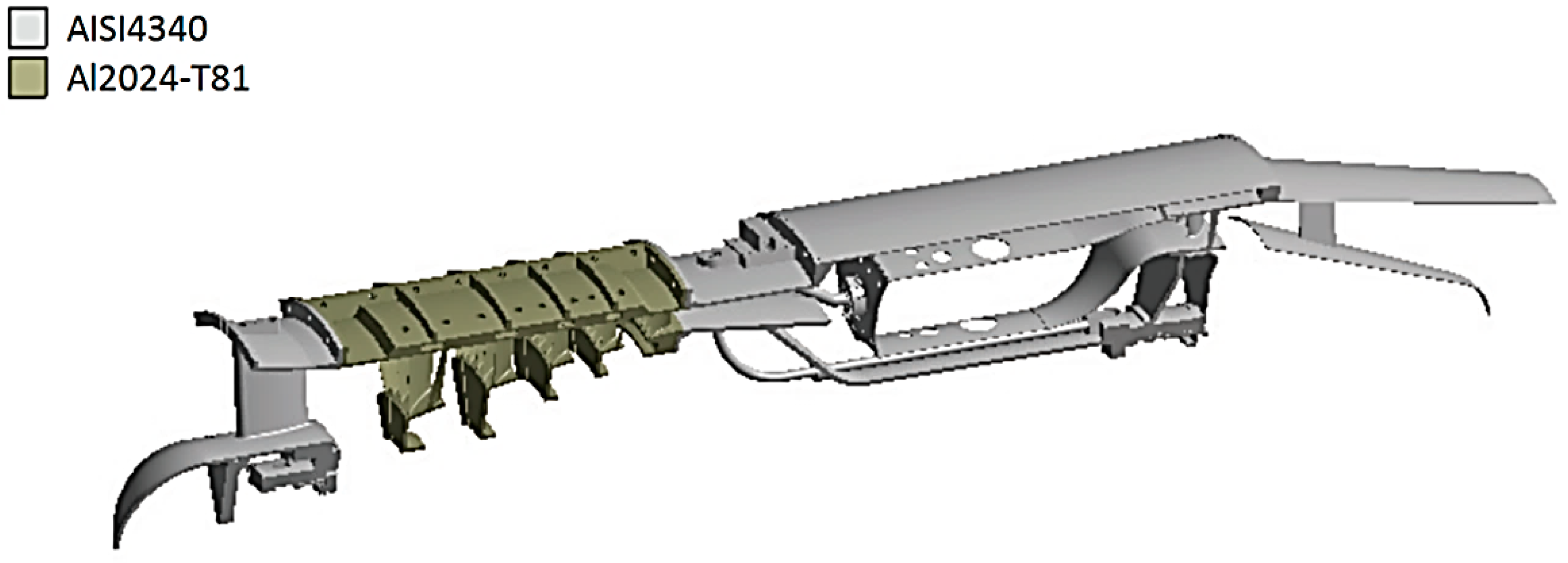
3. Materials and Boundary Conditions

The metallic alloys used to manufacture the single spool gas turbine are of paramount importance, since they will be subjected to high structural and thermal loads, and, consequently, they will be subjected to several failure modes. To illustrate, a few existing loads can be identified: centrifugal loads generated by rotational speed; tensile load due to thrust; pressure of gases that are compressed or expanded by discs blades or vanes, and, specially, high temperatures, which contribute to a reduction of the metallic alloys yield strengths and the appearance of high thermal stresses. Thus, very few metallic materials can be subjected to these conditions. Based on previous experience and acquired knowledge of other similar aeronautical gas turbine projects, the materials selected for the computational simulations are presented in Figure 3 and Figure 4, whose composition are given in Table 1.
The values of the main mechanical properties of the metallic alloys used in the computational simulations of this work are presented in Table 2. Additional information about temperature and creep data can be found at MatWeb.com [20]. The boundary conditions were obtained from the mathematical modeling presented in Section 2. Figure 5 shows the compressor and turbine stages with respective working fluid pressure measurement points. Table 3 shows the respective numerical values of working fluid pressure at the compressor and turbine stages. All the heat transfer coefficients used in the computational simulations are presented in Table 4.

4. Results and Discussion

Due to the radial symmetry of the engine, a one eighth section of the turbine was chosen for the model. The rotating and static components were analyzed independently. The turbine heat transfer analysis was performed using the heat transfer coefficients and the finite element method with the software Ansys. The geometries were modelled with hexadominant meshes composed mainly of hexahedral elements and their respective variations. All these elements have shown to provide sufficiently good results in heat transfer problems. In Ansys, a hexadominant solid mesh is formed with Solid186 elements. Solid186 is a higher order 3D 20-node solid element that exhibits quadratic displacement behavior. The element is defined by 20 nodes having 3 degrees of freedom per node: translations in the nodal x , y , and z directions. The element supports plasticity, hyperelasticity, creep, stress stiffening, large deflection, and large strain capabilities. It also has mixed formulation capability for simulating deformations of nearly incompressible elastoplastic materials, and fully incompressible hyperelastic materials. The geometry, node locations, and the element coordinate system for this element are shown in Figure 6. A prism-shaped element may be formed by defining the same node numbers for nodes K, L, and S; nodes A and B; and nodes O, P, and W. Similarly, pyramidal- and tetrahedral-shaped elements may also be formed as shown. Their respective shape functions and integration points can be found in [21,22].

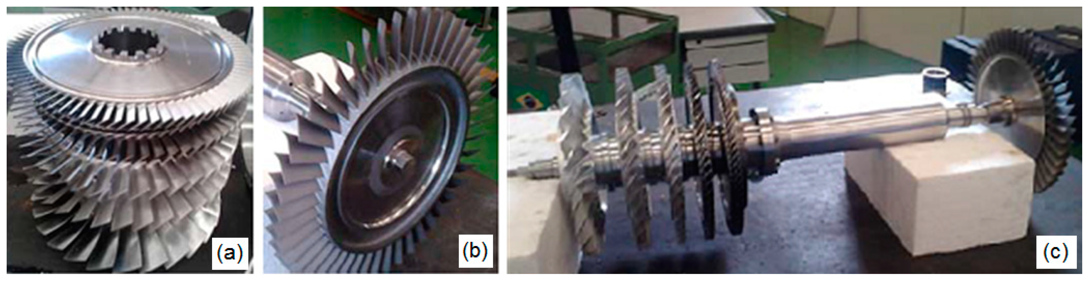
4.1. Temperature Distribution over the Rotating Assembly

Figure 7 shows the temperature distribution of the rotating assembly calculated by the finite element method. The boundary conditions were specified using the heat transfer coefficients calculated by the correlations presented previously.
Part of the air which leaves the compressor is used to seal the front bearing in order to prevent oil leakage. This air stream passes near the combustion chamber and gets into the interior of the shaft. From the interior of the shaft, the air is directed to the front bearing to accomplish its function of sealing. However, when the air passes near the region of the combustion chamber, it suffers a considerable temperature increase. At the compressor exit, the air temperature is about 210 °C and due to the heat transfers along the way, the air temperature reaches approximately 280 °C. This fact justifies the temperature over the interior of the shaft being higher than the temperature of the last compressor disc. This can be seen in Figure 8a. It is also interesting to note the temperature gradient on the interior surface of the shaft just below the compressor disc, Figure 8b. This temperature gradient is explained by the fact that the second, third and fourth discs do not touch the exterior surface of the shaft. Thus, at this location, the shaft does not lose heat by conduction through these rotors and an increase in temperature can be clearly observed in this region.
It is important to evaluate the temperature at certain points. Figure 9a emphasizes the temperature on the inner rear bearing ring surface, which can reach 114 °C. Figure 9b shows the difference in temperature from the front disc face to the rear disc face. The difference in temperature can reach 100 °C, which causes a distortion in the turbine disc geometry. This difference in temperature is due to the fact that the rear disc face is uncooled. Figure 9c shows the temperature distribution over a single turbine blade, being almost radial, as expected for an uncooled turbine blade.

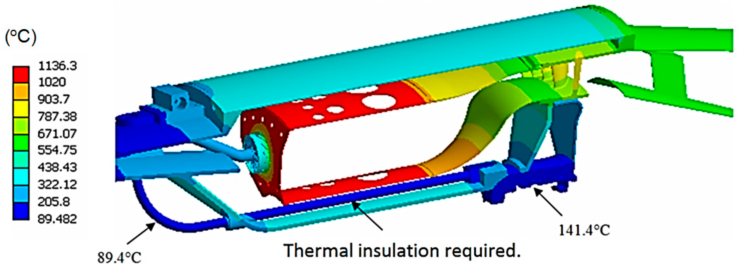
4.2. Temperature Distribution over the Static Assembly

Figure 10 shows the temperature distribution of the static assembly. In this analysis, it is very important to take into account the heat transfer by radiation, especially in those components near the combustion chamber. Figure 11 shows the temperature field over the compressor stator vanes. Higher temperatures are found on the last stages as expected.
The temperature distribution over the static components near the combustion chamber is shown in Figure 12. The lowest temperature is 89.4 °C and is located in the beginning of the feeding oil tube. Along this tube, thermal insulation is required to prevent oil overheating. The oil in this tube is responsible for refrigeration, lubrication, and reduction of vibration in the rear bearing since it is a squeeze film damper. The estimated temperature over the outer bearing ring is 141.4 °C. This temperature is calculated considering that the oil is at 95 °C in the rear bearing, limited by the oil cooling system.

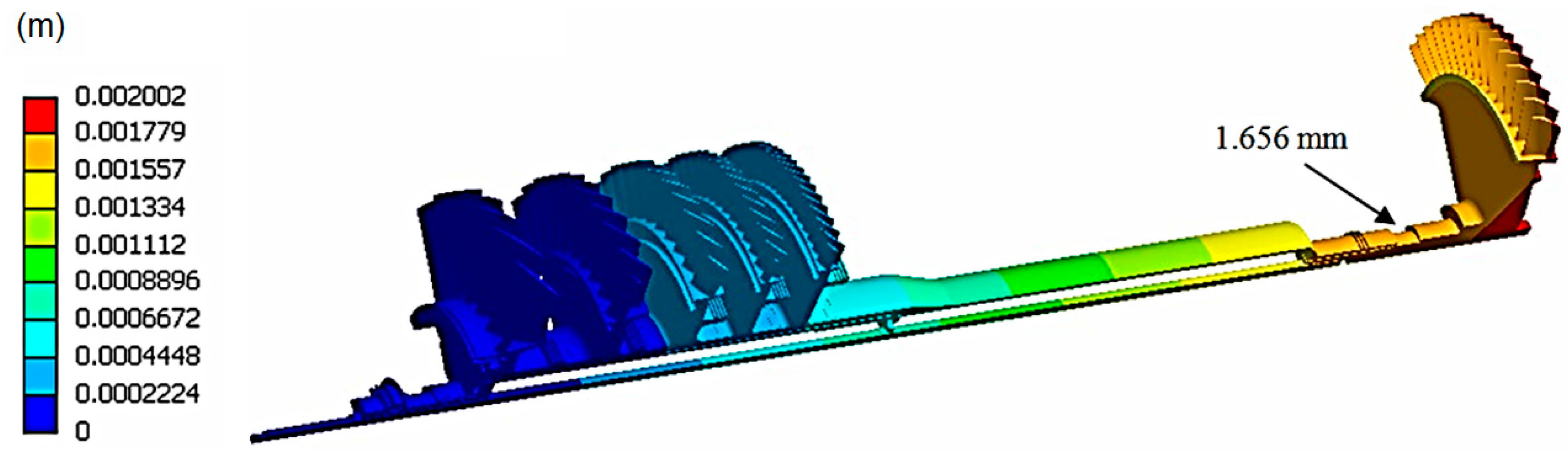
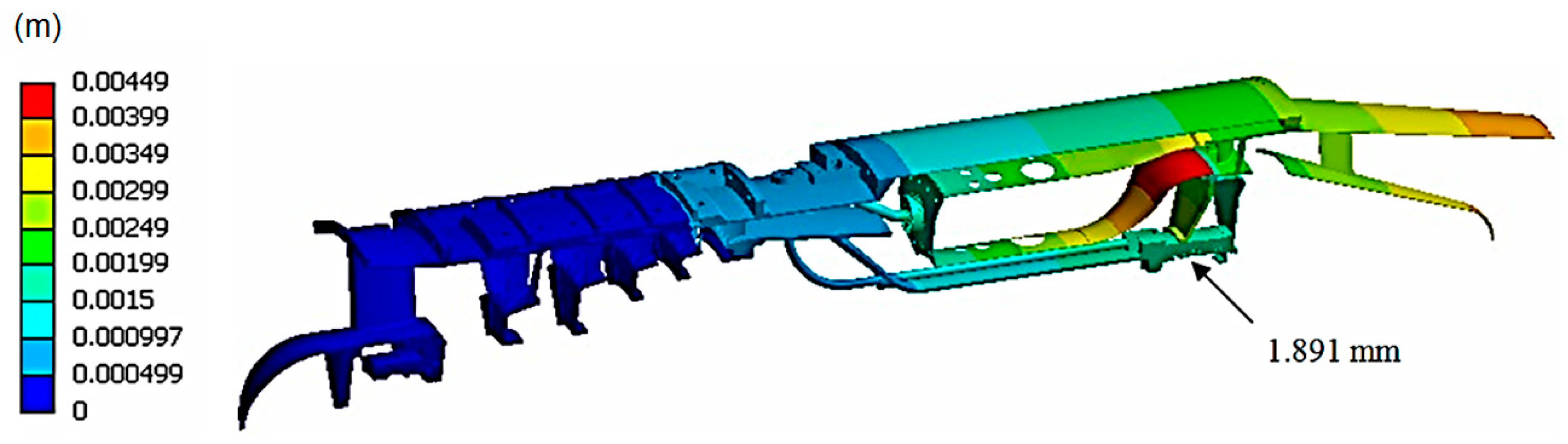
4.3. Thermal Expansion Behavior over the Rotating and Static Assemblies

Figure 13 shows the thermal expansion behavior along the rotating assembly. The displacement at the inner rear bearing ring surface is 1.656 mm. Figure 14 shows the thermal expansion behavior along the static assembly. The calculated displacement at the outer rear bearing ring surface is 1.891 mm. These analyses were performed by considering the design point conditions at maximum rotational speed. The rear bearing is a critical component regarding the thermal expansion effects. The thermal expansion variation between the rotating and static assemblies indicates that the rear bearing slides 0.235 mm towards the front bearing. The prediction of this movement allows the appropriate rolling bearing specification and its correct position in the whole bearing assembly.
Figure 15a shows the clearance in the coupling of the combustion chamber outer wall with the turbine stator at room temperature. The effect caused by thermal expansion at the design point conditions can be seen in Figure 15b. At room temperature the clearance measures 3.21 mm. After thermal expansion, the clearance reduces to 1.2 mm.
The lower part of the combustion chamber is simply supported by the turbine stator. The combustion chamber can slide, due to thermal expansion, over the turbine stator. Figure 16a shows the assembly position at room temperature. Figure 16b shows the new position after thermal expansion. After thermal expansion, the lower part of the combustion chamber slides 2.526 mm towards the turbine stator vanes, but no potential problem was observed.
It is also important to evaluate the clearances between the turbine rotor and the static components. Figure 17 shows the dimensions D1 and D2 evaluated at room temperature and after the thermal expansion using the design point conditions at the maximum rotational speed. D1 represents the clearance between the turbine disc and the turbine stator, and D2 represents the clearance between the turbine disc and the exhaustion duct. Dimension D1 measures 4.296 mm at room temperature and it has a reduction of 0.761 mm after thermal expansion. In the same way, dimension D2 measures 3.067 mm at room temperature and it has a reduction of 0.494 mm after thermal expansion.

5. Conclusions

A heat transfer analysis in a one eighth section of a single spool gas turbine has been successfully performed. The temperature distribution over the complete aeronautical gas turbine, including the rotating and static assemblies, have been estimated using the heat transfer correlations and the finite element method. The highest temperatures were found on the turbine blades considering the rotating components, and on the combustion chamber considering the static components. Film cooling is recommended on the combustion chamber due to the temperature peaks of 1136 °C. The temperature on the rear bearing is consistent with commercial rolling bearings operation limits. The oil tube must be insulated to avoid oil and bearing overheating. The thermal expansion behavior of the clearances was also evaluated. The gaps between the rotating and static components suffer a reduction after thermal expansion, but no overlapping or potential problem was found. It was observed that the rear bearing slides 0.235 mm towards the front bearing. The prediction of this movement allows an appropriate rolling bearing specification and the determination of its correct position along the whole bearing assembly. The thermal expansion behavior predicted on the one eighth section of the studied single spool gas turbine is consistent with acceptable practical values. Thus, the mechanical drawings can be released to manufacturing.

Author Contributions

Investigation, G.C. and M.T.d.M.; Formal analysis, G.C. and M.T.d.M.; Resources, J.C.M. and J.R.B.; Supervision, J.C.M. and J.R.B.; Project administration, J.R.B. All authors have read and agreed to the published version of the manuscript.

Funding

This research received no external funding.

Acknowledgments

All authors thank the support received and acknowledged in [1,2,3]. The first author would also like to thank CAPES and CNPq 385582/2006-4 for their financial support.

Conflicts of Interest

The authors declare no conflict of interest.

References

  1. Creci, G.; Menezes, J.C.; Barbosa, J.R.; Corra, J.A. Rotordynamic Analysis of a 5-Kilonewton Thrust Gas Turbine by Considering Bearing Dynamics. J. Propuls. Power 2011, 27, 330–336. [Google Scholar] [CrossRef]
  2. Creci Filho, G. Influência da Dinâmica dos Mancais na Resposta Vibratória de uma Turbina Aeronáutica de 5kN de Empuxo. Ph.D. Thesis, Instituto Tecnológico de Aeronáutica, São José dos Campos, Brazil, 2012; p. 307. Available online: http://www.bdita.bibl.ita.br/tesesdigitais/lista_resumo.php?num_tese=62130 (accessed on 20 November 2020).
  3. Creci, G.; Balastrero, J.O.; Domingues, S.; Torres, L.V.; Menezes, J.C. Influence of the Radial Clearance of a Squeeze Film Damper on the Vibratory Behavior of a Single Spool Gas Turbine Designed for Unmanned Aerial Vehicle Applications. Shock. Vib. 2017, 2017, 4312943. [Google Scholar] [CrossRef]
  4. Leme, A.D.S.; Creci, G.; De Jesus, E.R.B.; Rodrigues, T.C.; Menezes, J.C. Finite Element Analysis to Verify the Structural Integrity of an Aeronautical Gas Turbine Disc Made from Inconel 713LC Superalloy. Adv. Eng. Forum 2019, 32, 15–26. [Google Scholar] [CrossRef]
  5. Mazur, Z.; Luna-Ramírez, A.; Juárez-Islas, J.; Campos-Amezcua, A. Failure analysis of a gas turbine blade made of Inconel 738LC alloy. Eng. Fail. Anal. 2005, 12, 474–486. [Google Scholar] [CrossRef]
  6. Sadowski, T.; Golewski, P. Multidisciplinary analysis of the operational temperature increase of turbine blades in combustion engines by application of the ceramic thermal barrier coatings (TBC). Comput. Mater. Sci. 2011, 50, 1326–1335. [Google Scholar] [CrossRef]
  7. Kim, K.M.; Park, J.S.; Lee, D.H.; Lee, T.W.; Cho, H.H. Analysis of conjugated heat transfer, stress and failure in a gas turbine blade with circular cooling passages. Eng. Fail. Anal. 2011, 18, 1212–1222. [Google Scholar] [CrossRef]
  8. El-Batsh, H.M.; Nada, S.A.; Abdo, S.N.; El-Tayesh, A.A. Effect of Secondary Flows on Heat Transfer of a Gas Turbine Blade. Int. J. Rotating Mach. 2013, 2013, 797841. Available online: https://www.hindawi.com/journals/ijrm/2013/797841/ (accessed on 20 November 2020). [CrossRef] [Green Version]
  9. Fu, C.-Z.; Si, W.; Quan, L.; Yang, J. Numerical Study of Convection and Radiation Heat Transfer in Pipe Cable. Math. Probl. Eng. 2018, 2018, 5475136. [Google Scholar] [CrossRef] [Green Version]
  10. Bade, M.; Clark, N.N.; Robinson, M.C.; Famouri, P. Parametric Investigation of Combustion and Heat Transfer Characteristics of Oscillating Linear Engine Alternator. J. Combust. 2018, 2018, 2907572. [Google Scholar] [CrossRef] [Green Version]
  11. Dou, H.-S.; Jiang, G.; Zhang, L.-T. A Numerical Study of Natural Convection Heat Transfer in Fin Ribbed Radiator. Math. Probl. Eng. 2015, 2015, 989260. [Google Scholar] [CrossRef] [Green Version]
  12. Jedsadaratanachai, W.; Boonloi, A. Numerical Study on Turbulent Forced Convection and Heat Transfer Characteristic in a Circular Tube with V-Orifice. Model. Simul. Eng. 2017, 2017, 3816739. [Google Scholar] [CrossRef]
  13. Badreddine, H.; Sato, Y.; Berger, M.; Ničeno, B. A Three-Dimensional, Immersed Boundary, Finite Volume Method for the Simulation of Incompressible Heat Transfer Flows around Complex Geometries. Int. J. Chem. Eng. 2017, 2017, 1726519. [Google Scholar] [CrossRef] [Green Version]
  14. Devaraj, C.; Muthuswamy, E.; Kandasamy, S. Numerical Investigation of Laminar Natural Convection in Inclined Square Enclosure with the Influence of Discrete Heat Source. J. Appl. Math. 2015, 2015, 985218. [Google Scholar] [CrossRef] [Green Version]
  15. Schlichting, H. Boundary Layer Theory, 6th ed.; McGraw-Hill: New York, NY, USA, 1968; Available online: https://books.google.com.br/books?id=6IZTAAAAMAAJ (accessed on 20 November 2020).
  16. Colladay, R. Turbine Design and Application; NASA SP 290, Turbine Cooling; National Aeronautics and Space Administration, Lewis Research Center: Cleveland, OH, USA, 1975; Volume 3, pp. 59–101.
  17. White, F.M. Viscous Fluid Flow; McGraw-Hill: New York, NY, USA, 1974; Available online: https://books.google.com.br/books?isbn=007124493X (accessed on 20 November 2020).
  18. Evans, D.M. Calculation of Temperature Distribution in Multistage Axial Gas Turbine Rotor Assemblies When Blades Are Uncooled. J. Eng. Power 1973, 95, 309–318. [Google Scholar] [CrossRef]
  19. Lefebvre, A.H. Gas Turbine Combustion, 2nd ed.; Taylor & Francis Ltd.: Ann Arbor, MI, USA, 1999; Available online: https://books.google.com.br/books?isbn=1560326735 (accessed on 20 November 2020).
  20. MATWEB: Material Property Data. 2018. Available online: http://www.matweb.com/ (accessed on 20 November 2020).
  21. Zienkiewicz, O.C. The Finite Element Method; McGraw-Hill Company: London, UK, 1977; Available online: https://books.google.com/books?isbn=0070840725 (accessed on 20 November 2020).
  22. Moaveni, S. Finite Element Analysis: Theory and Application with Ansys; Prentice Hall: Upper Saddle River, NJ, USA, 1999; Available online: https://books.google.com/books?isbn=0137850980 (accessed on 20 November 2020).
  23. Ansys® Academic Research Documentation Manual, Release 18.2, Help System, Guide. ANSYS, Inc. Available online: https://www.ansys.com/ (accessed on 20 November 2020).
Figure 1. Illustration of the aeronautical gas turbine studied in this work on test rig: (a) Perspective view including inlet and exhaustion ducts; (b) Side view.
Applsci 10 08328 g001
Figure 2. Rotating assembly of the aeronautical gas turbine with its compressor and turbine discs: (a) Compressor discs; (b) Turbine disc; (c) All rotating assembly.
Applsci 10 08328 g002
Figure 3. A one eighth section of the rotating assembly showing the chosen metallic alloys for each component.
Applsci 10 08328 g003
Figure 4. A one-eighth section of the static assembly showing the chosen metallic alloys for each component.
Applsci 10 08328 g004
Figure 5. Working fluid pressures in measurement points at the compressor and turbine stages.
Applsci 10 08328 g005
Figure 6. Solid186 element in Ansys and its variations according to [23].
Applsci 10 08328 g006
Figure 7. Temperature distribution over a one eighth section of the rotating assembly.
Applsci 10 08328 g007
Figure 8. Temperature distribution over the compressor disc and shaft: (a) Perspective view; (b) Inner shaft view.
Applsci 10 08328 g008
Figure 9. (a) Temperature distribution over the turbine disc; (b) temperature distribution along the disc profile; (c) temperature distribution over a single turbine blade.
Applsci 10 08328 g009
Figure 10. Temperature distribution over one eighth section of the static assembly.
Applsci 10 08328 g010
Figure 11. Temperature distribution over the compressor stator vanes.
Applsci 10 08328 g011
Figure 12. Temperature distribution near the combustion chamber.
Applsci 10 08328 g012
Figure 13. Thermal expansion along the rotating assembly.
Applsci 10 08328 g013
Figure 14. Thermal expansion along the static assembly.
Applsci 10 08328 g014
Figure 15. Coupling of the combustion chamber outer wall with the turbine stator: (a) Position at room temperature; (b) new position after thermal expansion.
Applsci 10 08328 g015
Figure 16. Coupling of the combustion chamber inner wall with the turbine stator. (a) Position at room temperature; (b) new position after thermal expansion.
Applsci 10 08328 g016
Figure 17. Illustration of the clearances between the turbine disc and the static components.
Applsci 10 08328 g017
Table 1. Compositions of the metallic alloys in terms of elements percentage.
Metallic AlloysComposition
AISI4340C (0.37–0.43%); Cr (0.70–0.90%); Fe (95.195–96.33%) as remainder; Mn (0.60–0.80%); Mo (0.20–0.30%); Ni (1.65–2.0%); P (<=0.035%); Si (0.15–0.30%); S (<=0.040%).
Al2024-T81Al (90.7–94.7%) as remainder; Cr (<=0.10%); Cu (3.8–4.9%); Fe (<=0.50%);
Mg (1.2–1.8%); Mn (0.30–0.90%); Si (<=0.50%); Ti (<=0.15%); Zn (<=0.25%).
Al7178-T6Al (85.3–89.5%) as remainder; Cr (0.18–0.28%); Cu (1.6–2.4%); Fe (<=0.50%);
Mg (2.4–3.1%); Mn (<=0.30%); Si (<=0.40%); Ti (<=0.20%); Zn (6.3–7.3%).
In713LCAl (6.1%); B (1.012%); C (0.12%); Cr (12.5%); Ni (77.368%) as remainder;
Nb/Cb (2.0%); Ti (0.80%); Zr (0.10%).
Ti-6Al-4VAl (5.5–6.75%); C (<=0.080%); H (<=0.015%); Fe (<=0.40%); N (<=0.030%);
O (<=0.20%); Ti (87.725–91%) as remainder; V (3.5–4.5%).
Table 2. Basic properties at room temperature of the high-performance metallic alloys used.
PropertyAISI4340Al2024-T81Al7178-T6In713LCTI-6Al-4V
Young modulus205 GPa72.4 GPa71.7 GPa190 GPa113.8 GPa
Density 7850   kg / m 3 2780   kg / m 3 2830   kg / m 3 8000   kg / m 3 4430   kg / m 3
Yield strength862 MPa450 MPa540 MPa750 MPa873 MPa
Poisson’s ratio 0.29 0.33 0.33 0.382 0.342
Fatigue strength 150   MPa
( 1 × 10 6 )
125   MPa
( 5 × 10 8 )
150   MPa
( 5 × 10 8 )
150   MPa
( 1 × 10 9 )
150   MPa
( 5 × 10 8 )
Thermal conductivity 44.5   W / ( m . K ) 151   W / ( m . K ) 125   W / ( m . K ) 21.6   W / ( m . K ) 6.7   W / ( m . K )
Specific heat 475   J / ( kg . K ) 875   J / ( kg . K ) 856   J / ( kg . K ) 648   J / ( kg . K ) 526.3   J / ( kg . K )
Thermal expansion coefficient
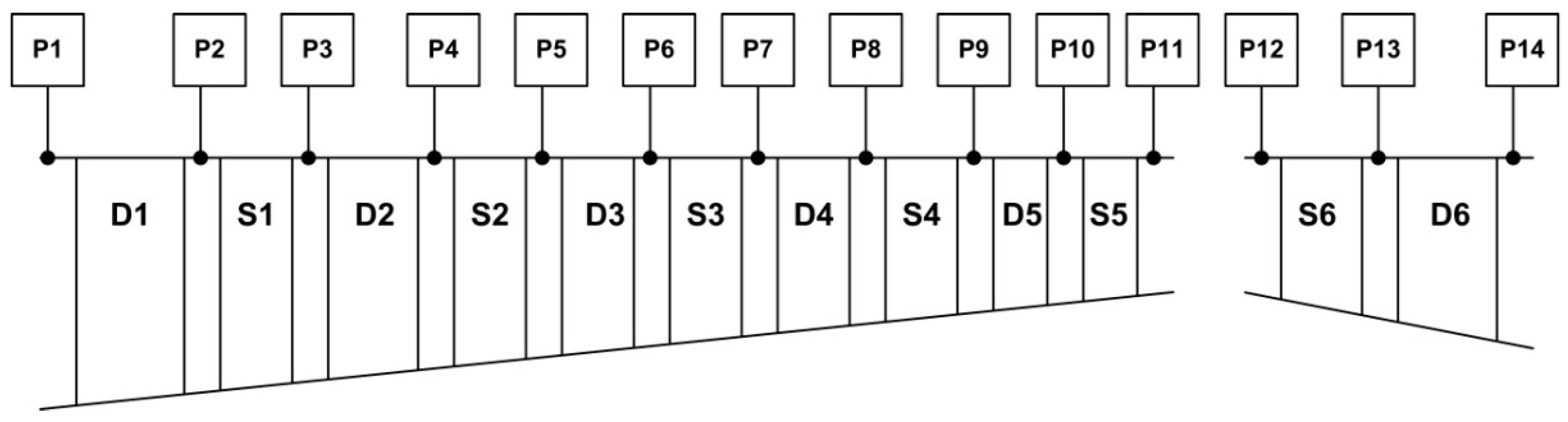
 13.7   μ m / ( m . K ) 23.2   μ m / ( m . K ) 23.4   μ m / ( m . K ) 10   μ m / ( m . K ) 12.4   μ m / ( m . K )
Table 3. Numerical values of working fluid pressures at the compressor and turbine stages.
Total Pressure (Pa)Static Pressure (Pa) Total Pressure (Pa)Static Pressure (Pa)
P1101,325.085,810.4P8494,712.9415,134.8
P2159,589.4131,760.6P9474,924.4444,226.1
P3153,205.8132,186.7P10633,281.3556,937.3
P4243,236.0185,535.1P11607,950.0580,379.0
P5233,506.6208,730.9P12476,227.5442,810.9
P6357,671.4286,118.7P13460,006.8265,130.2
P7343,364.6315,009.4P14223,318.8171,831.4
Table 4. Heat transfer coefficients used in the computational simulations.
Local Convective   Coefficient   ( W / ( m 2   ° C ) ) Temperature   ° C Local Convective   Coefficient   ( W / ( m 2   ° C ) ) Temperature   ( ° C )
Turbine blade convex surface1265706Compressor stator 4 blade surface2297162
Turbine blade concave surface975706Compressor stator 4 blade platform837162
Turbine blade tip surface840711Compressor stator 4 frontal surface744154
Turbine blade platform839699Compressor stator 4 back surface1111169
Turbine disc frontal surface397295Compressor stator 5 blade surface2561206
Turbine disc back surface794541Compressor stator 5 blade platform909206
Compressor disc 1 blade surface 130216Compressor stator 5 frontal surface933200
Compressor disc 1 blade platform 37516Compressor top surface 1st of 1334916
Compressor disc 1 blade tip surface34916Compressor top surface 2nd of 1337023
Compressor disc 1 frontal surface31915Compressor top surface 3rd of 1341737
Compressor disc 1 back surface40744Compressor top surface 4th of 1344344
Compressor disc 2 blade surface 146145Compressor top surface 5th of 1348055
Compressor disc 2 blade platform 46445Compressor top surface 6th of 13 53877
Compressor disc 2 blade tip surface44345Compressor top surface 7th of 1355888
Compressor disc 2 frontal surface42844Compressor top surface 8th of 13608100
Compressor disc 2 back surface56084Compressor top surface 9th of 13682125
Compressor disc 3 blade surface 187989Compressor top surface 10th of 13705137
Compressor disc 3 blade platform 57589Compressor top surface 11th of 13762150
Compressor disc 3 blade tip surface55889Compressor top surface 12th of 13820173
Compressor disc 3 frontal surface56884Compressor top surface 13th of 13 889205
Compressor disc 3 back surface742131Cover surface around compressor5020
Compressor disc 4 blade surface 2575137Rear bearing seal300130
Compressor disc 4 blade platform 723137Front bearing seal65045
Compressor disc 4 blade tip surface705137Front bearing stop45040
Compressor disc 4 frontal surface744131Spring of front bearing50025
Compressor disc 4 back surface944179Surface with oil at rear bearing285095
Compressor disc 5 blade surface 3410185Oil duct near front bearing1200100
Compressor disc 5 blade platform 841185Aerofoil and oil duct2561206
Compressor disc 5 blade tip surface823185Static rear part of oil duct200206
Compressor disc 5 frontal surface933179Front bearing oil duct 120070
Compressor disc 5 back surface1111218Frontal thermal shield300300
Turbine stator blade surface1250830Back thermal shield400310
Turbine stator blade platform850830Outlet exhaustion duct5020
Turbine stator top surface high1250830Exhaustion duct top surface820650
Turbine stator top surface low100300Exhaustion duct inferior surface820650
Turbine stator frontal surface500350Exhaustion duct support1000650
Turbine stator back surface 300300Exhaustion duct inner surface200541
Compressor stator 1 blade surface107730Combustion chamber surface 1st of 65601700
Compressor stator 1 blade platform41530Combustion chamber surface 2nd of 65601200
Compressor stator 1 frontal surface31930Combustion chamber surface 3rd of 6560900
Compressor stator 1 back surface56030Combustion chamber surface 4th of 6920300
Compressor stator 2 blade surface143965Combustion chamber surface 5th of 6400300
Compressor stator 2 blade platform53965Combustion chamber surface 6th of 6600300
Compressor stator 2 frontal surface42958Combustion chamber inner top900300
Compressor stator 2 back surface74272Cover around combustion chamber5020
Compressor stator 3 blade surface1795112Shaft end at rear bearing250300
Compressor stator 3 blade platform676112Shaft exterior surface400300
Compressor stator 3 frontal surface568104Shaft interior surface400260
Compressor stator 3 back surface944120Static rear part inner shaft900300
Static interior back part150250Static front part inner shaft400300
Static interior platform part200206Swiler500250
LocalEmissivity/Radiation Temperature   ( ° C )
Combustion chamber interior high0.61700
Combustion chamber interior medium0.61200
Combustion chamber interior low0.6900
Static part around combustion chamber0.6980
Static part below combustion chamber0.61100
Static part around turbine disc0.6600
Publisher’s Note: MDPI stays neutral with regard to jurisdictional claims in published maps and institutional affiliations.

