Abstract
Love wave sensors have attracted significant interest due to their high sensitivity and low attenuation. Love mode acoustic dispersion relation, highest normalized mass sensitivity, optimum normalized waveguide layer thickness, and temperature coefficients of frequency (TCF) were theoretically studied for the carbon fiber epoxy composites (CFEC)/Mn:0.24PIN-0.46PMN-0.30PT structure sensor. The highest normalized mass sensitivity exhibits a decreasing trend as the temperature increases from 25 °C to 55 °C. TCF can be improved by increasing the normalized layer thickness (h/λ); however, the temperature dependence of normalized mass sensitivity decreases. For the carbon fibers (CFs) in the CFEC waveguide along the propagation direction of Love wave, the device has a relatively small TCF of −10.92 ppm/°C at h/λ = 0.4001, where the normalized mass sensitivity is approximately 1.5 times that of a typical fused quartz/ST-quartz configuration device. The theoretical results imply that good temperature stability and high measurement precision were obtained from the device in the system CFEC/Mn:0.24PIN-0.46PMN-0.30PT with the CFs in the CFEC along the propagation direction of Love wave (x-axis). The ideal waveguide material requires a small elastic constant ; however, the ideal piezoelectric substrate requires large elastic constants and .
1. Introduction
Love wave sensors are highly sensitive acoustic devices, both in the liquid and gas phases, that can be used in immunoassay formats, detection of organic compounds, gas monitoring, etc. [1,2,3]. Love mode surface acoustic waves only exist in a thin waveguide/substrate layered structure, where the shear wave velocity in the waveguide layer is lesser than that in the piezoelectric substrate [4]. As is known, certain parameters, including elastic constants, dielectric constants, and piezoelectric constants, for most materials vary with ambient temperature. The change in waveguide and substrate material parameters will lead to a change in Love wave propagation characteristics, including phase velocity and frequency. For a Love wave device, the perturbation (mass loading) on the surface of waveguide layer can result in a change in frequency [4]. At a certain temperature, by measuring the frequency shift, the mass of the load can be obtained accurately when the mass sensitivity is provided. In general, the ambient temperature is not constant; therefore, it is very important to determine the relationship between mass sensitivity and temperature to ensure the measurement accuracy of the device.
To eliminate the influence of ambient temperature, temperature-compensated Love wave sensors have been studied. The temperature coefficient of frequency (TCF) is zero in theory for a SiO2/LiTaO3 structure device for a normalized layer thickness of 0.255; however, the sensitivity to mechanical surface perturbations of the structure is only approximately 50% of that of the traditional SiO2/quartz sensor [5]. Although the TCF can attain a very small value of +0.75 ppm/K for the polymethyl methacrylate (PMMA)/ST-quartz structure device for a normalized guiding layer thickness of 0.0381, the temperature compensation effect is weakened because of aging as the PMMA is a polymer and ages easily [6]. The temperature coefficient of delay (TCD) can reach zero and the mass sensitivity can be improved by adding a SiO2 buffer layer in the ZnO/Si structure device; however, the electromechanical coupling coefficient in the configuration is still very low [7]. For a device with multi-guide layers, a very small TCF of +2.16 ppm/°C was obtained with the SU-8/SiO2/ST-90°X quartz configuration, but the insertion loss increased with temperature [8]. Note that SU-8 is a cross-linked photoresist with a glass transition temperature of over 200 °C [9]. For practical Love wave devices, while attaining zero TCF, it is also necessary to maintain high sensitivity and high electromechanical coupling [10]. A dual-channel configuration of the delay-line oscillators was used to compensate for temperature drift [11,12,13,14]. The temperature effects can be compensated to a considerable degree by using dual-channel devices, but it is nevertheless of importance to minimize the temperature coefficient of oscillation frequency for the devices [15].
Choosing suitable waveguide materials will help improve the performance of the device. A polymer waveguide, such as PMMA and SU-8, exhibits the characteristics of low horizontal shear (SH) wave velocity and low density, which improve the performance. Low acoustic loss is also necessary for guiding layer materials for a practical Love wave device [15,16]. Although polymer waveguide can improve the mass sensitivity and temperature stability of devices [17], its high elastic attenuation will affect the performance of the device. High elastic attenuation means high acoustic loss of polymer waveguide. For a Love wave biosensor based on laser-deposited nanoporous gold sensitive films, the sensitivity and limit of detection (LOD) are considerably improved, compared with that of a dense gold layer [18]. Love wave sensors based on gold nanoparticle-modified polypyrrole show better gas sensing performance than the non-modified systems in dry conditions; the sensing response of the modified systems at room temperature may be attractive in gas detection [19]. For Love wave sensors with nanocrystalline diamond coating [20], the continuous nanocrystalline diamond layers increase the stiffness of the surface; however, the discrete nanocrystalline diamond coating improves entrapment of the Love waves in the guiding layer, which ensures high sensitivity. In the Love mode ammonia device based on graphene oxides (GO), the sensing layer’s stiffness is increased due to the oxygen-containing functional groups on the surface of GO, which also enhances the sensitivity and selectivity of the device at room temperature [21]. In most cases, two aluminum interdigital transducers (IDT) are embedded between the waveguide layer and the piezoelectric substrate through photolithography [22,23,24]. The acoustic impedance of carbon fiber epoxy composites is comparable to that of Al and SiO2, which implies low acoustic loss [25,26]. In addition, the elastic property of CFEC is almost invariable in the range of 25–55 °C [27]. Further, the density and SH wave velocity of CFEC are also very low.
Good temperature stability and high electromechanical coupling are generally required for piezoelectric substrate materials used in practical SH-type surface wave device [28]. In a Love wave device, choosing a piezoelectric substrate with a higher electromechanical coupling coefficient can reduce insertion loss [29]. In recent years, Mn-doped rhombohedral phase ternary single crystal yPb(In1/2Nb1/2)O3-(1-x-y)Pb(Mg1/3Nb2/3)O3-xPbTiO3 (Mn:PIN-PMN-PT) has attracted considerable attention for its excellent piezoelectric properties and high mechanical quality factor [30]. Some papers have reported that ternary PIN-PMN-PT single crystals have higher Curie temperature and phase-transition temperature (TC and TRT), which are advantageous for higher temperature applications [31,32,33,34]. Compared with the binary ferroelectric single crystal (such as PMN-PT), the Mn:PIN-PMN-PT single crystal exhibits a lower dielectric loss, smaller pyroelectric coefficient, and smaller relative dielectric permittivity [35]. In addition, the Mn:PIN-PMN-PT single crystals also possess high piezoelectric coefficients and electromechanical coupling [36]. To design high-precision and high-sensitivity Love wave devices with temperature compensation, the relationship between the normalized mass sensitivity and the ambient temperature must be understood clearly. A Love-mode sensor with a CFEC/PMN-PT layered structure has been studied theoretically at room temperature (~25 °C) [26], the maximum mass sensitivity of which is approximately 3 times that of a traditional SiO2/ST quartz configuration sensor. However, compared with the Mn:PIN-PMN-PT ternary single crystal, the temperature stability of the PMN-PT binary single crystal is not good. For the CFEC/PMN-PT structure device, the high mass sensitivity and precision can’t be maintained when the temperature changes. This study will address this limitation.
For the reasons mentioned above, an unidirectional CFEC is selected as the waveguide material, and the Mn-doped 0.24PIN-0.46PMN-0.30PT ternary single crystal is used as the substrate material of the Love wave sensor in this work. This paper reports on the theoretical characteristics of the temperature dependence for normalized mass sensitivity and the optimum design of normalized layer thickness of the CFEC/Mn:PIN-PMN-PT configuration device in the range of 25–55 °C. High temperature will accelerate aging of poled piezoelectric single crystal. In order to prolong the service life of sensor, the temperature of working environment should be far lower than the transition temperature of poled piezoelectric substrate. In addition, the mechanical quality factor Q of Mn:PIN-PMN-PT ternary single crystal decreases with temperature [34]. Taking these factors into account, we choose the temperature range of 25–55 °C.
2. Theory and Equation
The schematic of the operation principle of a Love wave device is shown in Figure 1. The layered structure without a loading layer is the basic structure for supporting the Love wave. The piezoelectric substrate was a Mn:0.24PIN-0.46PMN-0.30PT ternary single crystal poled along the [001]c pseudo-cubic direction. It is assumed that the [100]c pseudo-cubic direction of the single crystal was along the x direction. The guiding layer was the unidirectional CFEC. Both the poled ternary single crystal and unidirectional CFEC are elastically anisotropic. In our design, the CFs in the CFEC are oriented along the x or y axis. In both cases, the Love wave always propagates in the x direction.
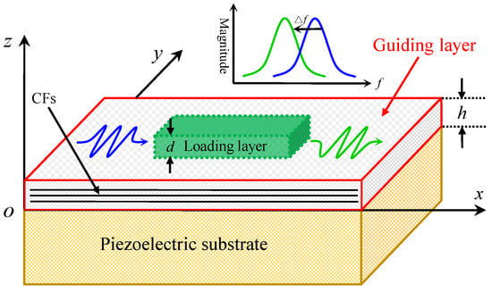
Figure 1.
Schematic of the sensor configuration and coordinate system.
Both PMN-PT binary single crystal and Mn:PIN-PMN-PT ternary single crystal are perovskite in structure. When the two single crystals are poled along the [001]c pseudo-cubic direction, they all have a 4mm macroscopic symmetry. Based on the partial wave theory applicable to anisotropic media [37,38,39,40], substituting the electrical and mechanical boundary conditions and material constants listed in Table 1 & Ref. [41] into the elastic wave equations and piezoelectric equations, the dispersion equation of Love mode surface acoustic waves can be derived as follows [26,42]:
where , , , , , , , v is the phase velocity of Love wave, h is the thickness of the waveguide layer, λ is the wavelength of Love wave, is the density, and the parameters labeled “^” denote the parameters of the guiding layer. In Table 1, for the x-axis, ; for the y-axis, .

Table 1.
Elastic constants of the CFEC for the CFs along the x-axis and y-axis.
The loading layer mass per unit area () induces a frequency shift as shown in Figure 1. According to the perturbation theory, the density and thickness of the loading layer are, respectively, and d [43], and the mass frequency sensitivity formula for a Love mode device is given as follows [4,15,26,42]:
where , f is the oscillation frequency for the perturbed case (mass loading), and are the frequency and SH wave velocity without mass loading respectively, is the shear wave speed in the loading layer, and is as follows:
The distributions of SH-type displacements normalized to that of the surface (z = h) can be written as follows [26,42]:
In general, there is no shear wave in liquid (e.g., water). Based on the Rayleigh hypothesis, the shear modulus of the loading layer is zero (), and the mass sensitivity formula becomes:
Substituting Equations (3)–(5) into Equations (6), the final mass sensitivity formula is derived as follows:
where , , and .
In general, materials with high electromechanical coupling coefficient also have high TCF [44], which can result in a frequency shift when the temperature changes. As mentioned above, a frequency shift occurs when the loading layer (mass loading) is placed on the guiding layer in Figure 1 at a fixed temperature. The perturbation (mass loading) frequency shift is the key of measurement. Obtaining the TCF can correct the measurement results and reduce the measurement error of the device. The TCF is given as [10,45,46]:
where f(Tmax), f(Tmin), and f(Tmid) are the center frequencies at temperatures Tmax, Tmin, and Tmid respectively, ΔT = Tmax − Tmin, Tmid = (Tmax + Tmin). Tmax = 55 °C, and Tmin = 25 °C in this work.
3. Results and Discussion
Using the dispersion Equation (1), and the material parameters of the CFEC and Mn:0.24PIN-0.46PMN-0.30PT piezoelectric single crystal, the dispersion curves of the Love mode surface acoustic waves for the CFs in the CFEC guiding layer along the x- and y-axes at 25 °C are shown in Figure 2a,b, respectively. All the dispersion curves in Figure 2 have the initial SH wave speed of 2809.9 m/s in the Mn:0.24PIN-0.46PMN-0.30PT ternary single crystal substrate, and each high-order Love mode has a low-frequency cut-off at this velocity. The velocities of Love waves asymptotically reach the SH wave speed of 1916 m/s in the waveguide with an increase in h/λ. By comparing Figure 2a,b, it is clear that the CFs orientation of the CFEC waveguide influence the propagation characteristics of the Love waves. The change in elastic constants c44 and c55 in Table 1 is the immediate cause of the variation of dispersion curves with different orientations of CFs. Different propagation characteristics of the Love waves will result in different performances of the devices with the CFs in the CFEC guiding layer parallel to the x-axis and y-axis. In the introduction, it is mentioned that the elastic property of CFEC is almost invariable in the range of 25–55 °C [27]. In fact, the change of elastic constants of CFEC with temperature is much smaller than that of Mn:0.24PIN-0.46PMN-0.30PT ternary single crystal in the range of 25–55 °C. Therefore, we assume that the elastic constants of CFEC are constant in the range of 25–55 °C. At temperatures 30, 35, 40, 45, 50, and 55 °C, we obtained dispersion relations similar to those in Figure 2. (see Appendix A) However, note that the SH mode wave speed in the substrate decreases with temperature (2761.1 m/s at 55 °C), while the low-frequency cut-offs of higher-order Love modes exhibit an increasing trend for a fixed CFs orientation.
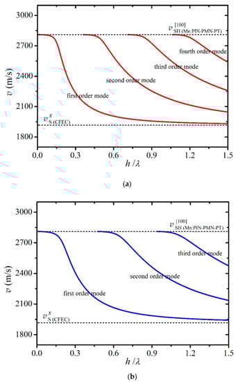
Figure 2.
Dispersion relation of Love waves at 25 °C. (a) CFs in CFEC waveguide along the x-axis. (b) CFs in CFEC waveguide along the y-axis.
Figure 3a,b show the relationship of normalized mass sensitivity against the normalized layer thickness h/λ for the CFEC/Mn:0.24PIN-0.46PMN-0.30PT structure device with the CFs in the CFEC waveguide parallel to the x- and y-axes at 25 °C. The order correspondence between Figure 2a and Figure 3a is the same as that between Figure 2b and Figure 3b. Both the highest normalized mass sensitivity and optimal normalized layer thickness are observed in the first order mode as shown in Figure 3. For each order mode, the normalized mass sensitivity increases rapidly to the maximum value and then decreases slowly, approaching zero, with the normalized layer thickness h/λ. By comparing Figure 3a,b, for the same order modes, we can see that the devices with the CFs in the guiding layer along the x-axis (the propagation direction of the Love wave) have higher normalized mass sensitivity at the maximum values. A Love wave sensor is expected to have the high mass sensitivity in practical applications. For a fixed wavelength and fiber orientation, the optimal waveguide thickness h of the first order mode is much less than that of higher-order modes.
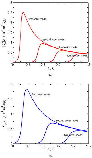
Figure 3.
Normalized mass sensitivity against normalized layer thickness for the CFEC/Mn-doped 0.24PIN-0.46PMN-0.30PT structure sensor at 25 °C. (a) CFs in CFEC along the x-axis. (b) CFs in CFEC along the y-axis.
For a feasible sensor design, the greater the waveguide thickness h, the higher the acoustic loss [16]. In addition, the first order mode has the highest electromechanical coupling factor [4]. Hence, the device has an optimal performance in the first order mode. As shown in Figure 3a,b, employing first order mode, the optimal normalized layer thickness was 0.2023 and 0.2691, and the highest normalized mass sensitivity was 2.5052 and 1.8261, which is approximately 2.5 times and 1.8 times of that of a fused quartz/ST-quartz structure device, respectively [4]. Clearly, for a given piezoelectric substrate, the device with a smaller elastic constant c44 of the CFEC waveguide has a higher normalized mass sensitivity.
Figure 4a,b show the normalized mass sensitivity for the first order mode for the CFEC/Mn:0.24PIN-0.46PMN-0.30PT structure device with the CFs in the guiding layer along the x-axis and y-axis, respectively, at different temperatures. The peak values of normalized mass sensitivity from Figure 4 are listed in Table 2, which indicate that the highest normalized mass sensitivity decreases with temperature for a fixed fibers orientation. Meanwhile, the optimum design exhibits a gradual increasing tendency, while the phase velocities () of the Love waves for the first order mode at the optimums exhibit a decreasing trend, and the elastic constants and of the substrate also show a decline. By comparing Figure 4a,b, for a given temperature in the range of 25–55 °C, the device with the CFs in the CFEC waveguide layer along the x-axis has the highest normalized mass sensitivity. Further, the optimal normalized layer thickness of the waveguide with the fibers along the x-axis is less than that of the fibers along the y-axis, which implies lower acoustic loss for a fixed wavelength.
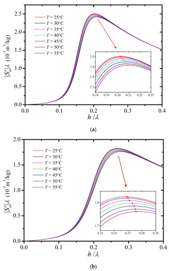
Figure 4.
Normalized mass sensitivity for the sensor operating in first order mode with CFEC/Mn:0.24PIN-0.46PMN-0.30PT configuration in the range of 25–55°C. (a) CFs along the x-axis. (b) CFs along the y-axis.
Table 2.
Optimum design parameters of normalized layer thickness and corresponding highest normalized mass sensitivity for a sensor operating in the first order mode with the unidirectional CFEC/Mn:0.24PIN-0.46PMN-0.30PT structure at different temperatures.
The peak values in Figure 4 are the simulation data of the highest normalized mass sensitivity and the optimum design at different temperatures. Figure 5 shows the fitted data, and the fitting equations for the two cases with the CFs in the CFEC waveguide along the x-axis and y-axis are as follows:
where Equations (9) and (10) describe the case that the CFs are parallel to the x-axis, and Equations (11) and (12) describe the case that the CFs are parallel to the y-axis.
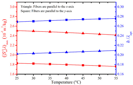
Figure 5.
Fitted curves of the highest normalized mass sensitivity and optimum design of normalized layer thickness for the first order mode sensor with the CFEC/Mn:0.24PIN-0.46PMN-0.30PT structure in the range of 25–55 °C.
From Figure 5 and Table 2, it was found that the changing trend of the highest normalized mass sensitivity is considerably dependent on the variation in elastic constants and of the Mn:0.24PIN-0.46PMN-0.30PT single crystal with temperature. Although the optimal design exhibited a slight increasing trend, it was almost invariant from 25 °C to 55 °C for a fixed CFs orientation.
Figure 6 shows the relationship of TCF and h/λ for the two devices operating in the first order mode with the fibers in the guiding layer along the x-axis and y-axis. The TCF tends to zero with an increase in the normalized layer thickness h/λ for a given fiber orientation, as shown in Figure 6. For a given h/λ, the |TCF| of the device with the CFs in the guiding layer along the x-axis is smaller than that of the CFs along the y-axis. Optimizing the thickness of the waveguide layer can improve the TCF [10]. Although a zero TCF can be achieved by increasing h/λ, the normalized mass sensitivity is reduced, as shown in Figure 4a,b. The wavelength λ in the normalized layer thickness h/λ is the distance between adjacent interdigital electrodes of IDT. Generally, the wavelength λ is a fixed value (e.g., 24 μm). In this case, increasing h/λ means increasing h. It is reported that the acoustic loss increases with the increase of waveguide thickness h [16]. Therefore, we can’t make h too large. In addition, see Figure 4a, to ensure that the device has a relatively high mass sensitivity, the normalized layer thickness can’t be increased unboundedly. Based on these reasons, it is necessary to balance the TCF and normalized mass sensitivity when optimizing the normalized layer thickness.
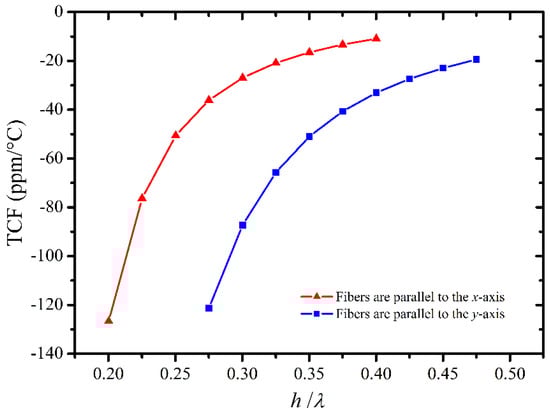
Figure 6.
TCF for different normalized layer thicknesses of the devices in the system CFEC/Mn:0.24PIN-0.46PMN-0.30PT.
From Figure 4a,b, the curves at different temperatures reach their highest point and then gradually merge together with increasing h/λ. Table 3 shows TCF and normalized mass sensitivity for the CFs in CFEC waveguide along the x-axis. When TCF = −126.62 ppm/°C, normalized mass sensitivity varies from 2.5043 to 2.4006; however, when TCF = −10.92 ppm/°C, the varies from 1.5228 to 1.5183 (the change is less than 0.3%) in the range of 25–55 °C. This means that the variation in normalized mass sensitivity with temperature can be ignored when a relatively high h/λ is employed. For the CFs in the guiding layer along the x-axis, the device has a relatively small TCF of −10.92 ppm/°C at h/λ = 0.4001, where the normalized mass sensitivity can be maintained at approximately 1.5 times that of a fused quartz/ST-quartz structure device. And, at h/λ = 0.4001, the normalized mass sensitivity can be considered to be approximately constant for the CFs are parallel to x-axis in the range of 25–55 °C. Hence, the temperature stability of the device can be improved by appropriately increasing the thickness of the waveguide for a fixed wavelength.
Table 3.
TCF and normalized mass sensitivity for a sensor operating in the first order mode with the CFs in CFEC waveguide along the x-axis.
4. Conclusions
In this article, the Love mode acoustic dispersion relation, normalized mass sensitivity, optimum normalized waveguide layer thickness, and TCF were calculated for the CFEC/Mn:0.24PIN-0.46PMN-0.30PT structure sensor. For a given piezoelectric substrate, the smaller the elastic constant c44 of the guiding layer, the higher normalized mass sensitivity of device. For a fixed waveguide layer, the highest normalized mass sensitivity decreases with temperature, which is considerably dependent on the change in the elastic constants and of Mn:0.24PIN-0.46PMN-0.30PT ternary single crystal substrate. The optimal design is approximately invariant for the CFEC waveguide with a fixed CFs orientation in the range of 25–55 °C. For the CFs in the CFEC waveguide along the propagation direction of Love wave, the sensor has a relatively small TCF of −10.92 ppm/°C at h/λ = 0.4001, where the normalized mass sensitivity is approximately 1.5 times that of a typical fused quartz/ST-quartz configuration device. It may provide some beneficial changes, including low density and acoustic loss, and good thermal stability by varying the content of the CFs in CFEC waveguide, which can improve device performance. Although the Mn:PIN-PMN-PT ternary single crystal has high electromechanical coupling and good temperature stability, the elastic constants and of Mn:0.24PIN-0.46PMN-0.30PT slightly decrease with temperature. Thus, it is important to find a substrate material that has large electromechanical coupling coefficients and elastic constants and . Besides waveguide and substrate, the operating frequency is also a key parameter [47,48]. When the frequency increases, the wave attenuation in substrate is stronger. If the thickness of substrate is lower than the penetration depth of the Love wave, loss of energy occurs [47]. The piezoelectric substrate of sensor be considered to be a semi-infinite medium in this work. In this paper we present a new waveguide/substrate system of Love wave device that has potential to maintain a high mass sensitivity with a relatively small temperature coefficients of frequency. In addition, this work provides a new idea to improve the polymer waveguide. For example, the unidirectional CFs may be added into PMMA to reduce the acoustic loss of PMMA.
Author Contributions
Methodology, N.H. and E.S.; Software, R.Z. and N.H.; Validation, B.Y., J.L. and T.L.; writing—original draft preparation, N.H. and W.C.; Writing—review and editing, N.H., L.H. and E.S.; Funding acquisition, N.H. All authors have read and agreed to the published version of the manuscript.
Funding
This research was supported in part by the Basic Scientific Research Foundation of College and University in Heilongjiang Province, China (Grant No. 2018QNL-16), the NSFC under Grant Nos. 51774092, 11304061 and 51572056 and Natural Science Foundation of Heilongjiang Province (LH2020E012).
Acknowledgments
The authors thank Xudong Qi (Harbin Normal University, Harbin, China) for his advice on mathematical program.
Conflicts of Interest
The authors declare no conflict of interest.
Appendix A
The Annex lists and briefly discusses four graphs. Figure A1 and Figure A2 are similar to Figure 2 in the article, and Figure A3 and Figure A4 are similar to Figure 3 in the article.

Figure A1.
Dispersion relation of Love waves for CFs in CFEC waveguide along the x-axis. (a) at 40 °C. (b) at 55 °C.
Figure A1.
Dispersion relation of Love waves for CFs in CFEC waveguide along the x-axis. (a) at 40 °C. (b) at 55 °C.

The SH wave velocity in the Mn:0.24PIN-0.46PMN-0.30PT decreases with the temperature as shown in Figure 2a and Figure A1a,b.

Figure A2.
Dispersion relation of Love waves for CFs in CFEC waveguide along the y-axis. (a) at 40 °C. (b) at 55 °C.
Figure A2.
Dispersion relation of Love waves for CFs in CFEC waveguide along the y-axis. (a) at 40 °C. (b) at 55 °C.

The SH wave velocity in the Mn:0.24PIN-0.46PMN-0.30PT decreases with the temperature as shown in Figure 2b and Figure A2a,b. By comparing Figure A1 with Figure A2, it is also found that the CFs orientation in the CFEC waveguide influence the propagation characteristics of the Love waves.

Figure A3.
Normalized mass sensitivity against normalized layer thickness for the CFEC/Mn:0.24PIN-0.46PMN-0.30PT configuration sensor with CFs in CFEC along the x-axis. (a) at 40 °C. (b) at 55 °C.
Figure A3.
Normalized mass sensitivity against normalized layer thickness for the CFEC/Mn:0.24PIN-0.46PMN-0.30PT configuration sensor with CFs in CFEC along the x-axis. (a) at 40 °C. (b) at 55 °C.

The highest normalized mass sensitivity decreases with temperature for the same order as shown in Figure 3a and Figure A3a,b.

Figure A4.
Normalized mass sensitivity against normalized layer thickness for the CFEC/Mn:0.24PIN-0.46PMN-0.30PT configuration sensor with CFs in CFEC along the y-axis. (a) at 40 °C. (b) at 55 °C.
Figure A4.
Normalized mass sensitivity against normalized layer thickness for the CFEC/Mn:0.24PIN-0.46PMN-0.30PT configuration sensor with CFs in CFEC along the y-axis. (a) at 40 °C. (b) at 55 °C.

References
- Puiu, M.; Gurban, A.M.; Rotariu, L.; Brajnicov, S.; Viespe, C.; Bala, C. Enhanced Sensitive Love Wave Surface Acoustic Wave Sensor Designed for Immunoassay Formats. Sensors 2015, 15, 10511–10525. [Google Scholar] [CrossRef] [PubMed]
- Nikolaou, I.; Hallil, H.; Plano, B.; Deligeorgis, G.; Conedera, V.; Garcia, H.; Dejous, C.; Rebière, D. Drop-casted Graphene Oxide Love wave sensor for detection of humidity and VOCs. J. Integr. Circuits Syst. 2016, 11, 49–56. [Google Scholar]
- Wang, W.; Fan, S.Y.; Liang, Y.; He, S.T.; Pan, Y.; Zhang, C.H.; Dong, C. Enhanced Sensitivity of a Love Wave-Based Methane Gas Sensor Incorporating a Cryptophane-A Thin Film. Sensors 2018, 18, 3247. [Google Scholar] [CrossRef] [PubMed]
- Jakoby, B.; Vellekoop, M.J. Properties of Love waves: Applications in sensors. Smart Mater. Struct. 1997, 6, 668–679. [Google Scholar] [CrossRef]
- Herrmann, F.; Weihnacht, M.; Büttgenbach, S. Temperature-compensated Love mode sensors based on quartz/SiO2 and LiTaO3/SiO2 systems. Proc. SPIE-Int. Soc. Opt. Eng. Adv. Environ. Chem. Sens. Technol. 2001, 4205, 180–187. [Google Scholar]
- Chen, X.; Liu, D.L. Temperature stability of ZnO-based Love wave biosensor with SiO2 buffer layer. Sens. Actuators A 2009, 156, 317–322. [Google Scholar] [CrossRef]
- Hu, Y.W.; Xiang, J.W.; Sun, X.Y. Temperature Compensation Experiment of Love Wave Sensor. Adv. Mater. Res. 2012, 490, 673–677. [Google Scholar] [CrossRef]
- Xu, F.Q.; Wang, W.; Hou, J.L.; Liu, M.H. Temperature Effects on the Propagation Characteristics of Love Waves along Multi-Guide Layers of SiO2/Su-8 on St-90° X Quartz. Sensors 2012, 12, 7337–7349. [Google Scholar] [CrossRef]
- Zhang, Y.; Lin, C.T.; Yang, S. Fabrication of hierarchical pillar arrays from thermoplastic and photosensitive SU-8. Small 2010, 6, 768–775. [Google Scholar] [CrossRef]
- Jakoby, B.; Bastemeijer, J.; Vellekoop, M.J. Temperature-compensated Love-wave sensors on quartz substrates. Sens. Actuators 2000, 82, 83–88. [Google Scholar] [CrossRef]
- Harding, G.L.; Du, J.; Dencher, P.R.; Barnett, D.; Howe, E. Love wave acoustic immunosensor operating in liquid. Sens. Actuator A 1997, 61, 279–286. [Google Scholar] [CrossRef]
- Jakubik, W.P.; Urbańczyk, M.W.; Kochowski, S.; Bodzenta, J. Bilayer structure for hydrogen detection in a surface acoustic wave sensor system. Sens. Actuators B 2002, 82, 265–271. [Google Scholar] [CrossRef]
- Jakubik, W.P.; Urban´czyk, M.W.; Kochowski, S.; Bodzenta, J. Palladium and phthalocyanine bilayer films for hydrogen detection in a surface acoustic wave sensor system. Sens. Actuators B 2003, 96, 321–328. [Google Scholar] [CrossRef]
- Yang, Y.; Zhu, D.Z. A Y type SAW mass sensor with metal array reflectors. Sens. Actuators B 2005, 109, 244–248. [Google Scholar] [CrossRef]
- Du, J.; Harding, G.L. A multilayer structure for Love-mode acoustic sensors. Sens. Actuators A 1998, 65, 152–159. [Google Scholar] [CrossRef]
- Wang, Z.; Cheeke, J.D.N.; Jen, C.K. Sensitivity analysis for Love mode acoustic gravimetric sensors. Appl. Phys. Lett. 1994, 64, 2940. [Google Scholar] [CrossRef]
- Wang, W.; Xie, X.; Hou, J.L.; He, S.T. Love Wave Devices with Excellent Temperature Stability for Application in Gas Sensor; IEEE Sensors: Taipei, Taiwan, 2012; pp. 1–4. [Google Scholar]
- Viespe, C.; Dinca, V.; Popescu-Pelin, G.; Miu, D. Love Wave Surface Acoustic Wave Sensor with Laser-Deposited Nanoporous Gold Sensitive Layer. Sensors 2019, 19, 4492. [Google Scholar] [CrossRef]
- Šetka, M.; Bahos, F.A.; Matatagui, D.; Potoček, M.; Kral, Z.; Drbohlavová, J.; Gràcia, I.; Vallejos, S. Love wave sensors based on gold nanoparticle-modified polypyrrole and their properties to ammonia and ethylene. Sens. Actuators B Chem. 2020, 304, 127337. [Google Scholar] [CrossRef]
- Drbohlavová, L.; Fekete, L.; Bovtun, V.; Kempa, M.; Taylor, A.; Liu, Y.; Bou Matar, O.; Talbi, A.; Mortet, V. Love-wave devices with continuous and discrete nanocrystalline diamond coating for biosensing applications. Sens. Actuators A 2019, 298, 111584. [Google Scholar] [CrossRef]
- Tang, Q.B.; Guo, Y.J.; Tang, Y.L.; Long, G.D.; Wang, J.L.; Li, D.J.; Zu, X.T.; Ma, J.Y.; Wang, L.; Torun, H.; et al. Highly sensitive and selective Love mode surface acoustic wave ammonia sensor based on graphene oxides operated at room temperature. J. Mater. Sci. 2019, 54, 11925–11935. [Google Scholar] [CrossRef]
- Chen, G.; Xie, X.; Wang, W.; He, S.T. An experimental research of love wave sensor based on LiTaO3/SiO2 structure. In Proceedings of the 2014 Symposium on Piezoelectricity, Acoustic Waves, and Device Applications, Beijing, China, 30 October–2 November 2014; pp. 1–4. [Google Scholar]
- Wang, W.; Xie, X.; Chen, G.; Liu, J.L.; He, S.T. Temperature-compensated Love wave based gas sensor on waveguide structure of SiO2/36° YX LiTaO3. Smart Mater. Struct. 2015, 24, 065019. [Google Scholar] [CrossRef]
- Bahos, F.A.; Vallejos, S.; Gràcia, I.; Cané, C.; Fernández, M.J.; Horrillo, M.C.; Matatagui, D. High-Performance Ammonia Sensor at Room Temperature Based on a Love-Wave Device with Fe2O3@WO3-x Nanoneedles. Proceedings 2017, 1, 484. [Google Scholar] [CrossRef]
- Kalantar Zadeh, K.; Trinchi, A.; Wlodarski, W.; Holland, A. A novel Love-mode device based on a ZnO/ST-cut quartz crystal structure for sensing applications. Sens. Actuators A 2002, 100, 135–143. [Google Scholar] [CrossRef]
- Huang, N.X.; Lü, T.Q.; Zhang, R.; Cao, W.W. High sensitivity gravimetric sensor made of carbon fiber epoxy composite on Pb(Mg1/3Nb2/3)O3-PbTiO3 single crystal substrate. Appl. Phys. Lett. 2013, 103, 053507. [Google Scholar] [CrossRef]
- Sathish, S.; Welter, J.; Reibel, R.; Buynak, C. Thermo-Elastic Characterization of Heat Damage in Carbon Fiber Epoxy Composites. AIP Conf. Proc. 2006, 820, 1015–1018. [Google Scholar]
- Nakamura, K.; Kazumi, M.; Shimizu, H. SH-type and Rayleigh-type surface waves on rotated Y-cut LiTaO3. In 1977 Ultrasonics Symposium; IEEE: Piscataway, NJ, USA, 1977; pp. 819–822. [Google Scholar]
- Liu, J.S.; He, S.T. Theoretical analysis on Love waves in a layered structure with a piezoelectric substrate and multiple elastic layers. J. Appl. Phys. 2010, 107, 073511. [Google Scholar] [CrossRef]
- Ou, W.C.; Li, S.Y.; Cao, W.W.; Yang, M. A single-mode Mn-doped 0.27PIN-0.46PMN-0.27PT single-crystal ultrasonic motor. J. Electroceram. 2016, 37, 121–126. [Google Scholar] [CrossRef]
- Zhou, Y.M.; Li, Q.; Zhuo, F.P.; Yan, Q.F.; Zhang, Y.L.; Chu, X.C. Anisotropic field induced phase transitions and negative electrocaloric effect in rhombohedral Mn doped Pb(In1/2Nb1/2)O3-Pb(Mg1/3Nb2/3)O3-PbTiO3 single crystals. Ceram. Int. 2018, 44, 9045–9052. [Google Scholar] [CrossRef]
- Chen, Y.; Lam, K.H.; Zhou, D.; Yue, Q.W.; Yu, Y.X.; Wu, J.C.; Qiu, W.B.; Sun, L.; Zhang, C.; Luo, H.S.; et al. High Performance Relaxor-Based Ferroelectric Single Crystals for Ultrasonic Transducer Applications. Sensors 2014, 14, 13730–13758. [Google Scholar] [CrossRef]
- Zhang, S.J.; Li, F. High performance ferroelectric relaxor-PbTiO3 single crystals: Status and perspective. J. Appl. Phys. 2012, 111, 031301. [Google Scholar] [CrossRef]
- Zhang, S.J.; Li, F.; Sherlock, N.P.; Luo, J.; Lee, H.J.; Xia, R.; Meyer Jr, R.J.; Hackenberger, W.; Shrout, T.R. Recent developments on high Curie temperature PIN–PMN–PT ferroelectric crystals. J. Cryst. Growth 2011, 318, 846–850. [Google Scholar] [CrossRef] [PubMed]
- Li, Y.; Tang, Y.X.; Chen, J.W.; Zhao, X.Y.; Yang, L.R.; Wang, F.F.; Zeng, Z.H.; Luo, S. Enhanced pyroelectric properties and thermal stability of Mn-doped 0.29Pb(In1/2Nb1/2)O3-0.29Pb(Mg1/3Nb2/3)O3-0.42PbTiO3 single crystals. Appl. Phys. Lett. 2018, 112, 172901. [Google Scholar] [CrossRef]
- Huo, X.Q.; Zhang, S.J.; Liu, G.; Zhang, R.; Luo, J.; Sahul, R.; Cao, W.W.; Shrout, T.R. Complete set of elastic, dielectric, and piezoelectric constants of [011]c poled rhombohedral Pb(In0.5Nb0.5)O3-Pb(Mg1/3Nb2/3)O3-PbTiO3:Mn single crystals. J. Appl. Phys. 2013, 113, 074106. [Google Scholar] [CrossRef] [PubMed]
- Chen, C.W.; Zhang, R.; Chen, H.; Cao, W.W. Guided wave propagation in 0.67Pb(Mg1/3Nb2/3)O3-0.33PbTiO3 single crystal plate poled along [001]c. Appl. Phys. Lett. 2007, 91, 02907. [Google Scholar] [CrossRef]
- Nayfeh, A.H.; Chien, H.T. The influence of piezoelectricity on free and reflected waves from fluid-loaded anisotropic plates. J. Acoust. Soc. Am. 1992, 91, 1250–1261. [Google Scholar] [CrossRef]
- Yang, C.H.; Chimenti, D.E. Acoustic waves in a piezoelectric plate loaded by a dielectric fluid. Appl. Phys. Lett. 1993, 63, 1328. [Google Scholar] [CrossRef]
- Yang, C.H.; Chimenti, D.E. Guided plate waves in piezoelectrics immersed in a dielectric fluid. I. Analysis. J. Acoust. Soc. Am. 1995, 97, 2103–2109. [Google Scholar] [CrossRef]
- Tang, L.G.; Tian, H.; Zhang, Y.; Cao, W.W. Temperature dependence of dielectric, elastic, and piezoelectric constants of [001]c poled Mn-doped 0.24Pb(In1/2Nb1/2)O3-0.46Pb(Mg1/3Nb2/3)O3-0.30PbTiO3 single crystal. Appl. Phys. Lett. 2016, 108, 082901. [Google Scholar] [CrossRef]
- Huang, N.X.; Lü, T.Q.; Zhang, R.; Cao, W.W. High sensitivity gravimetric sensor made of unidirectional carbon fiber epoxy composite on (1-x)Pb(Zn1/3Nb2/3)O3-xPbTiO3 single crystal substrate. Chin. Phys. B 2014, 23, 117704. [Google Scholar] [CrossRef]
- Auld, B.A. Acoustic Fields and Waves in Solids; Wiley: New York, NY, USA, 1976; Volume 2, Chapter 12; pp. 271–332. [Google Scholar]
- Liu, Q.; Flewitt, A.J. On-chip temperature-compensated Love mode surface acoustic wave device for gravimetric sensing. Appl. Phys. Lett. 2014, 105, 213511. [Google Scholar] [CrossRef]
- Chu, S.Y.; Water, W.; Liaw, J.T. A Study of Love Wave Acoustic Sensors in ZnO/Quartz Structure. Integr. Ferroelectr. 2002, 44, 91–100. [Google Scholar] [CrossRef]
- Water, W.; Yan, Y.S. Characteristics of strontium-doped ZnO films on love wave filter applications. Thin Solid Film. 2007, 515, 6992–6996. [Google Scholar] [CrossRef]
- Le Pommellec, J.Y.; El Baroudi, A. Viscoelastic fluid effect on the surface wave propagation. Sens. Actuators A 2019, 291, 188–195. [Google Scholar]
- Liu, J.S.; Wang, L.J. Dynamics and response of a humidity sensor based on a Love wave device incorporating a polymeric layer. Sens. Actuators B 2014, 204, 50–56. [Google Scholar] [CrossRef]


Publisher’s Note: MDPI stays neutral with regard to jurisdictional claims in published maps and institutional affiliations. |
© 2020 by the authors. Licensee MDPI, Basel, Switzerland. This article is an open access article distributed under the terms and conditions of the Creative Commons Attribution (CC BY) license (http://creativecommons.org/licenses/by/4.0/).