Study on Mechanical Properties of Multi-Cavity Steel–Concrete Composite Floor


Abstract
:1. Introduction
- (1)
- The bottom steel plate of multi-cavity steel plate framework can be used as the stressed steel bar in use phase, and the porous steel plates can be used as the distribution steel bar and shear steel bar in the floor, so as to enhance the bending resistance and the shear capacity of the floor, make full use of the material properties of the steel, and the process of binding the steel bars in the field is avoided;
- (2)
- The multi-cavity steel plate framework is produced by factory prefabrication, which can be used as the formwork in the construction stage of composite floor, and can bear the construction load such as concrete dumping load, simplifies the construction process on site and improves the construction efficiency;
- (3)
- The steel plate cavity inside the composite floor can effectively overcome the problems of concrete cracking and crack exposure. The steel plate cavity has a strong lateral restraint effect on the concrete and gives full play to the compressive performance of concrete;
- (4)
- In the composite floor, a steel plate cavity is used instead of the stressed steel bar and stirrup, which can avoid the excessive steel bar in the traditional floor due to the excessive bearing capacity of the floor, so that the internal concrete filling of the floor is not saturated during the concrete pouring, which affects the overall performance of the concrete components.
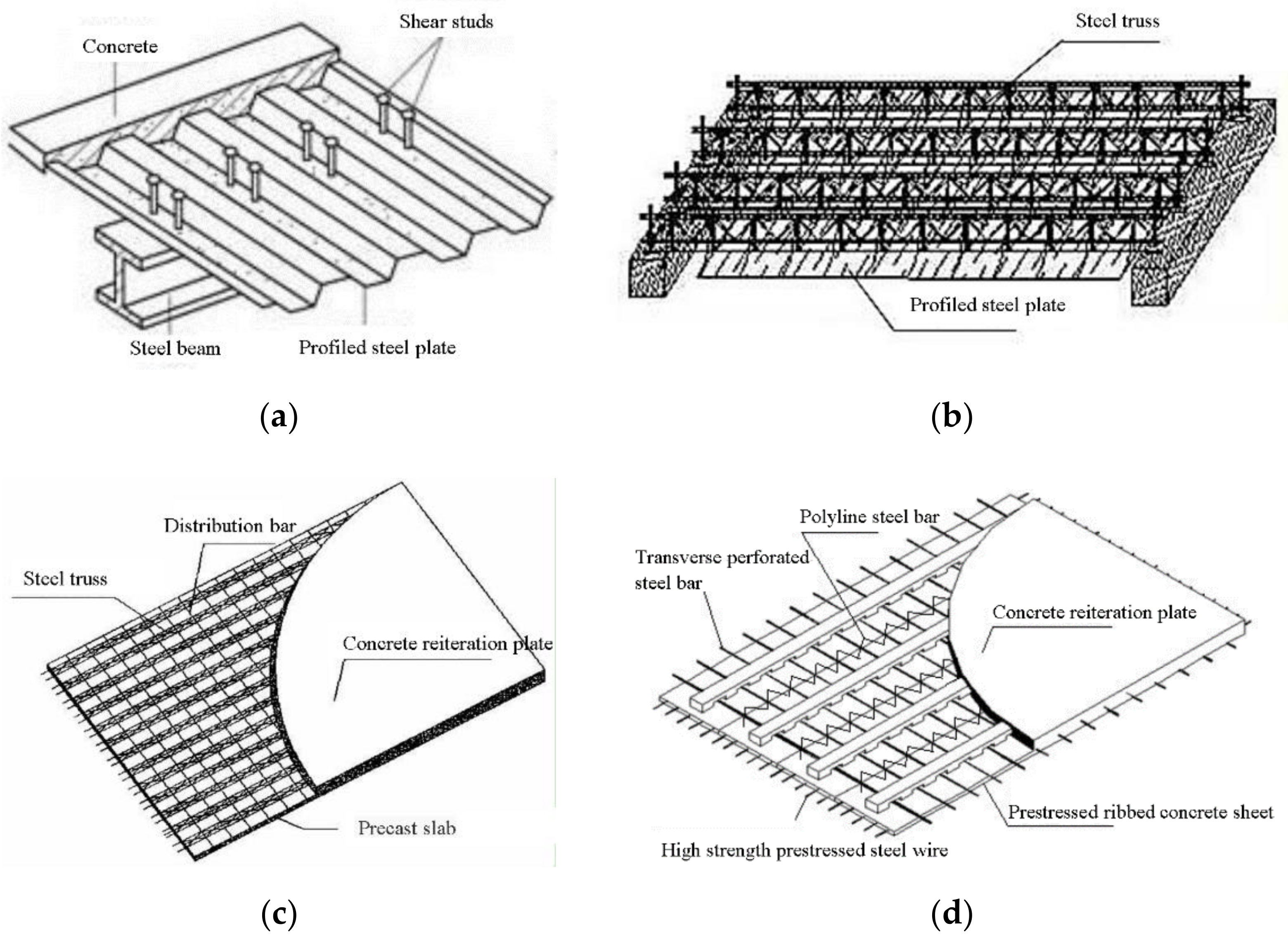
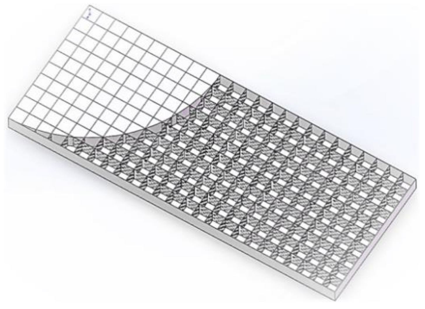
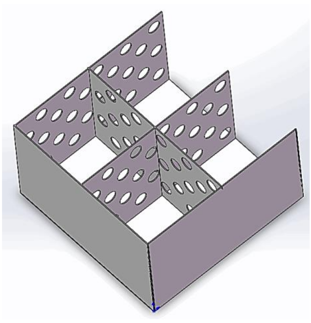
2. Structure and Prefabrication
2.1. Structure
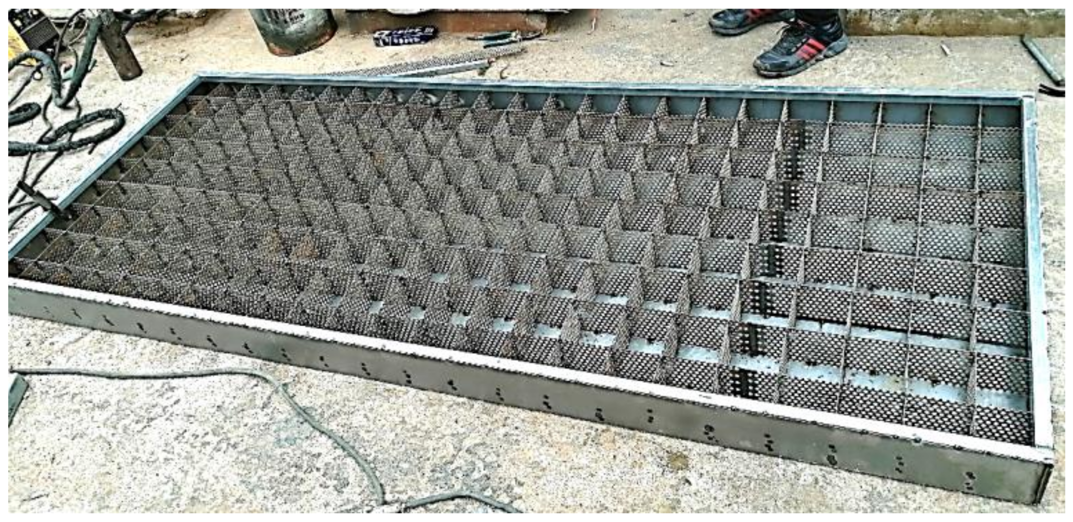
2.2. Prefabrication
3. Experimental Details
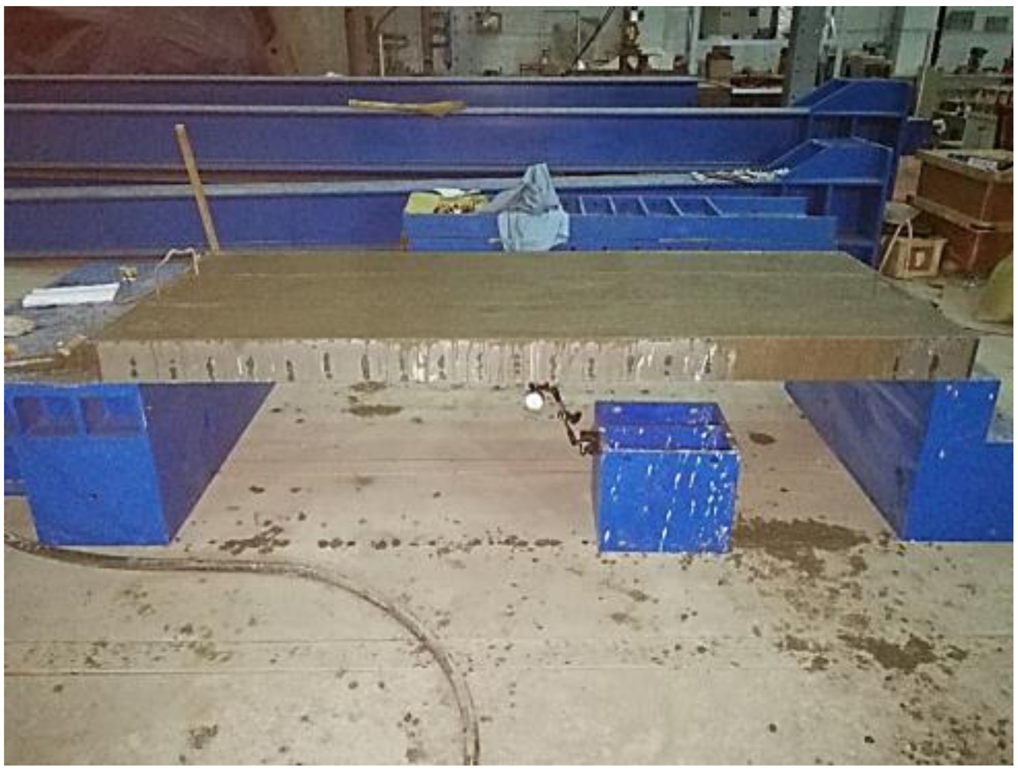
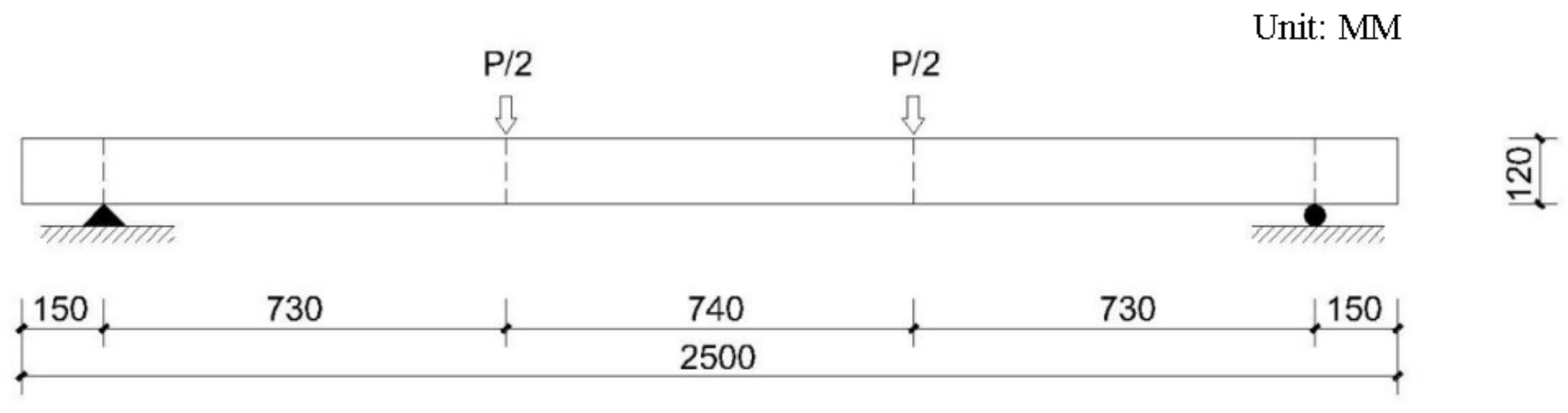
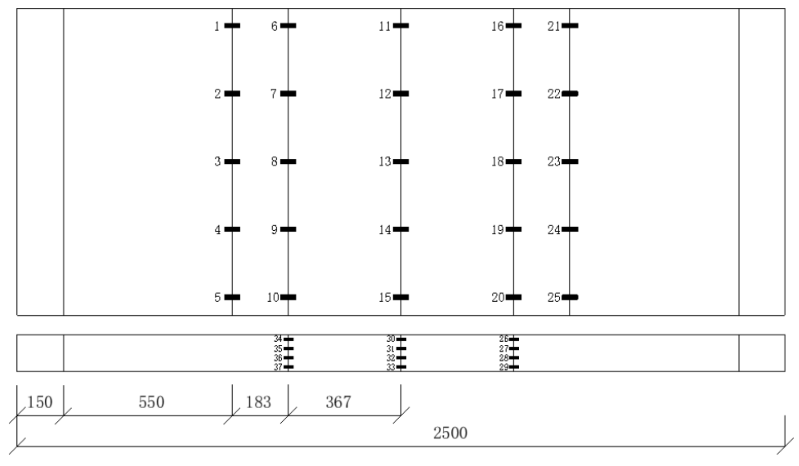
3.1. Design and Fabrication of Specimens
3.2. Materials
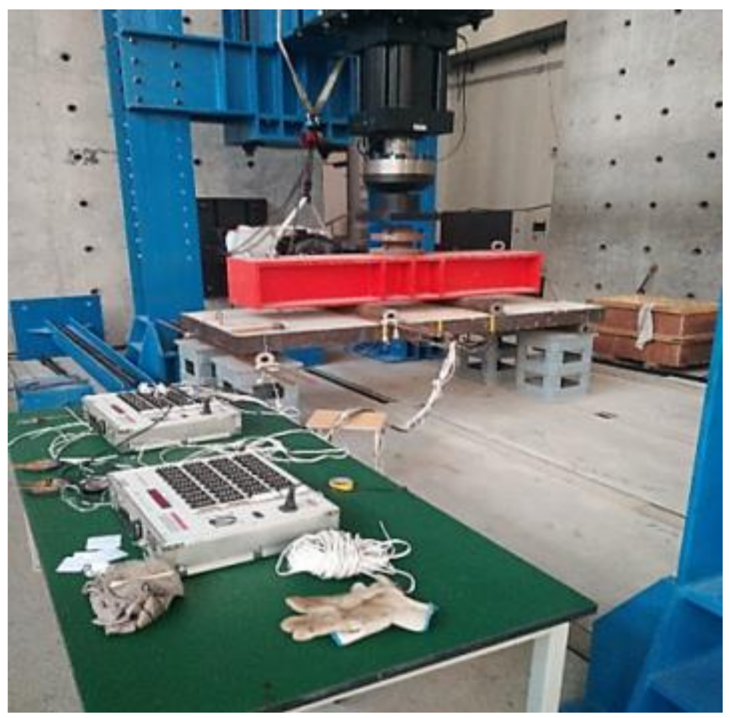
3.3. Test Set-Up
3.4. Loading Procedure
4. Results and Analysis
4.1. Failure Process
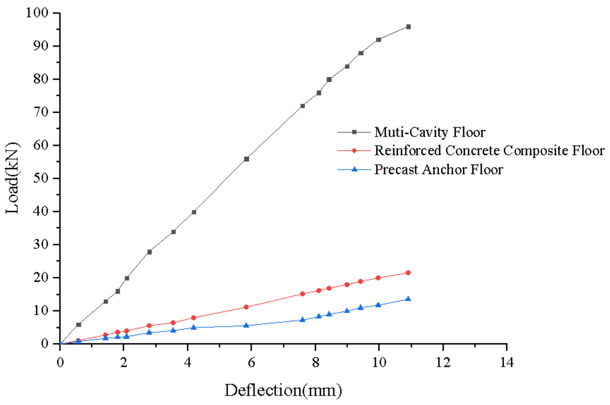
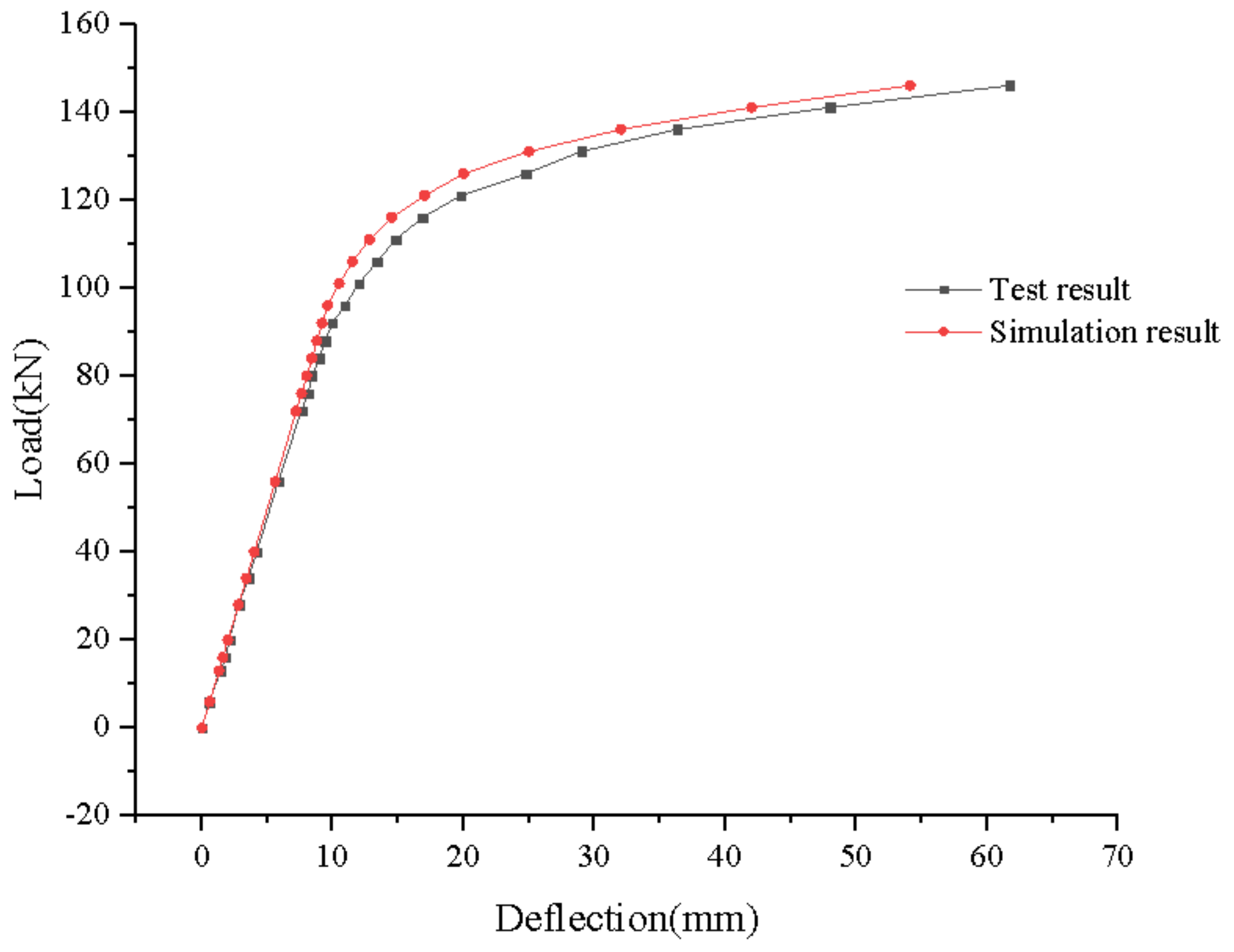
4.2. Load-Deflection Curve
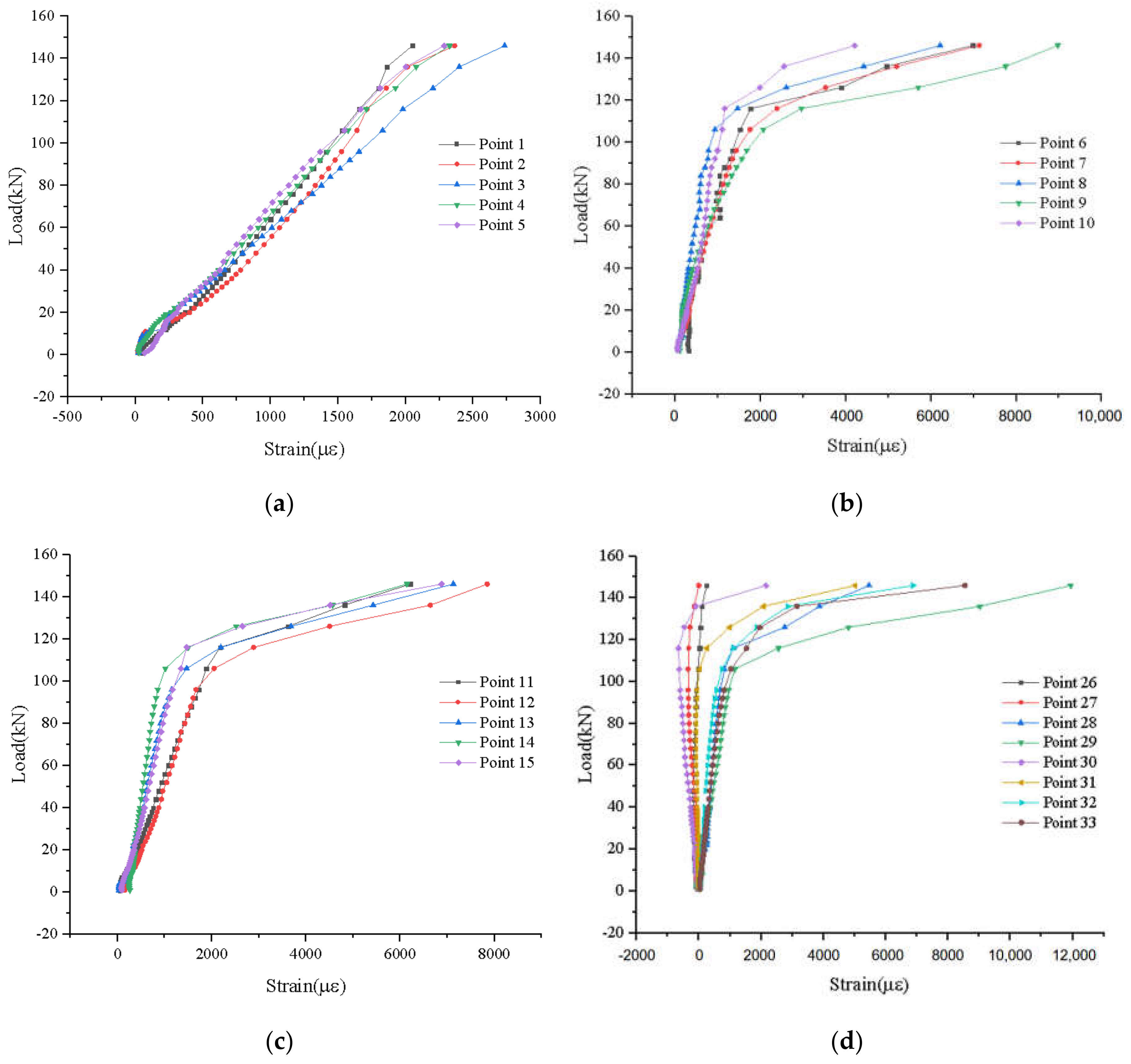
4.3. Load Strain Curve of Composite Floor
5. Finite Element Modeling Investigation
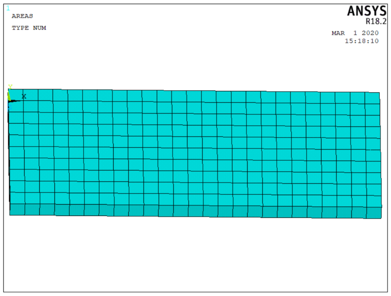
5.1. Finite Element Model Description
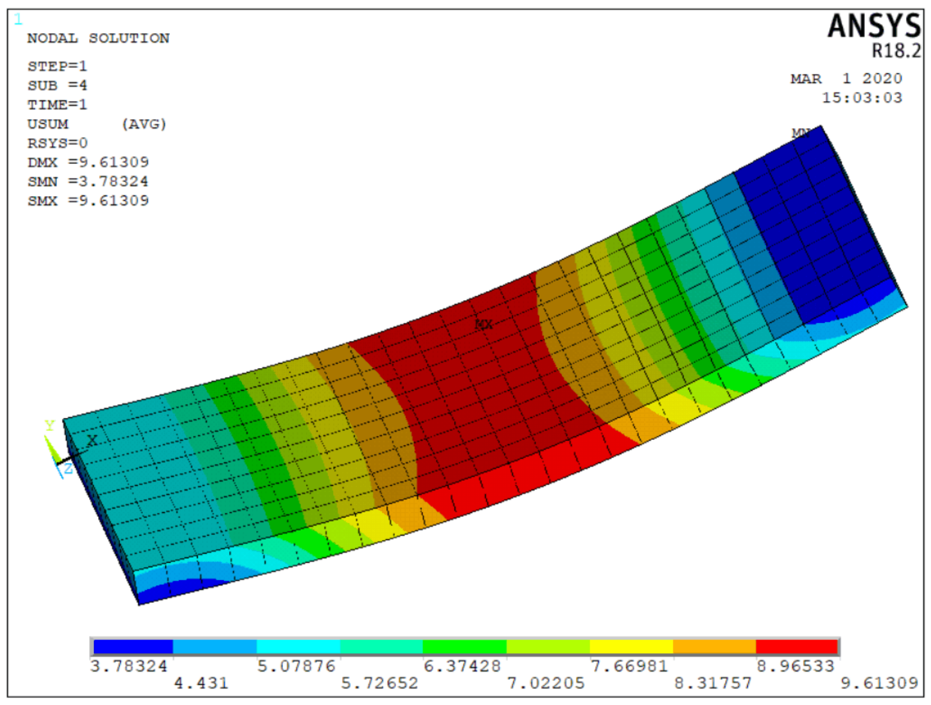
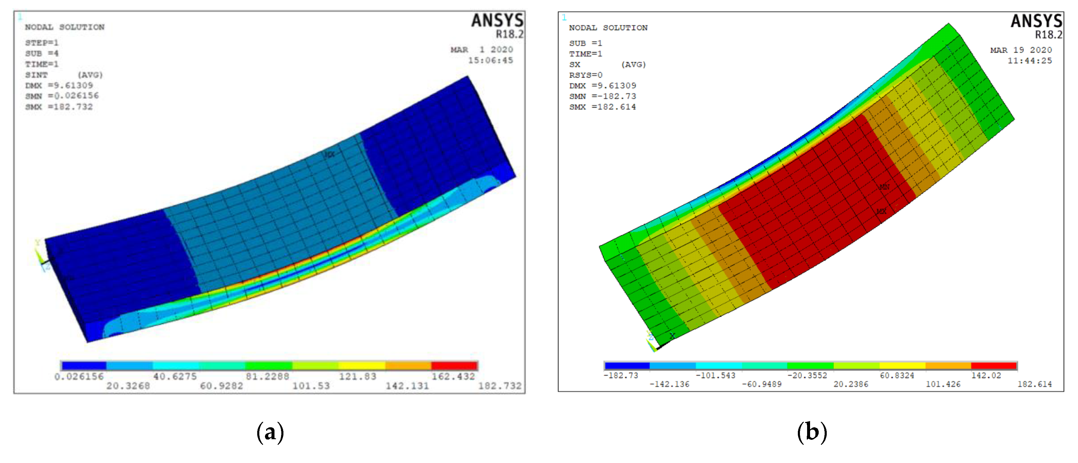
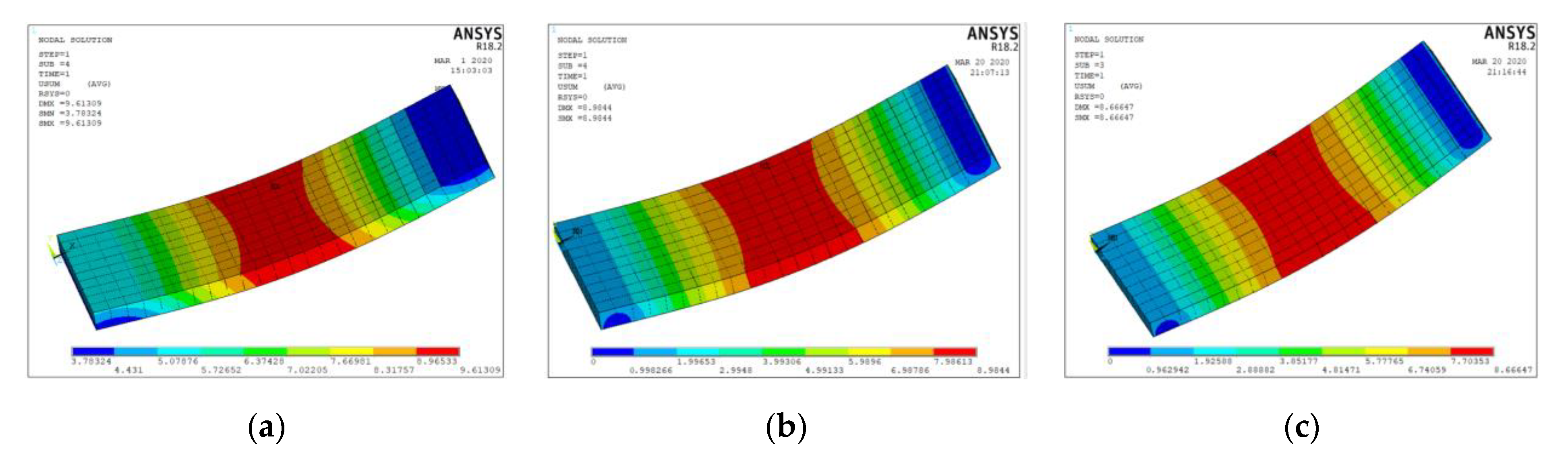
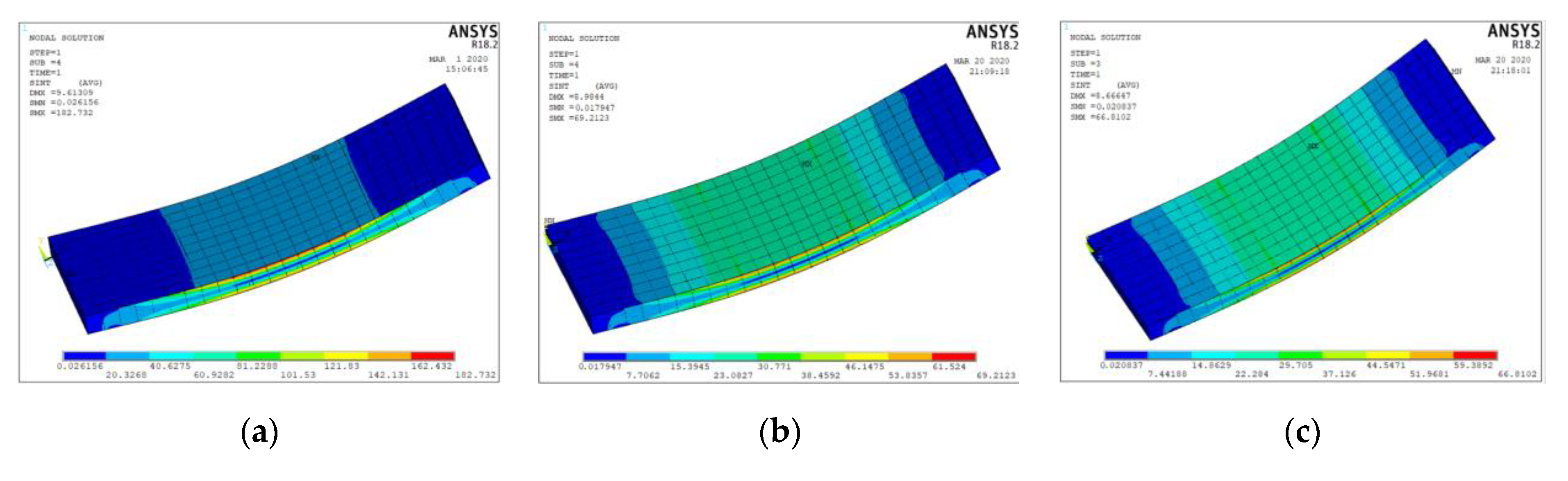
5.2. Finite Element Model Result
- (1)
- In the simulation, the constraint condition and load application were ideal. However, in the test, the x-direction displacement at the two simply-supported points was unlikely to be zero under load. Therefore, during the loading process, the two sides of the composite floor moved to the middle, which led to the increase in the mid span deflection.
- (2)
- Insufficient displacement transducers were set up, which made the test data slightly deviate. The displacement transducer might be disturbed if it is fixed at the center of composite floor when the composite floor is damaged. Therefore, only one displacement transducer was set up at the bottom surface of midspan. The upper part of the actuator which applies load on the span is a spherical hinge. Therefore, during the loading process, the composite floor may incline slightly to the side with the displacement transducer. For these reasons, the simulation results are relatively accurate.
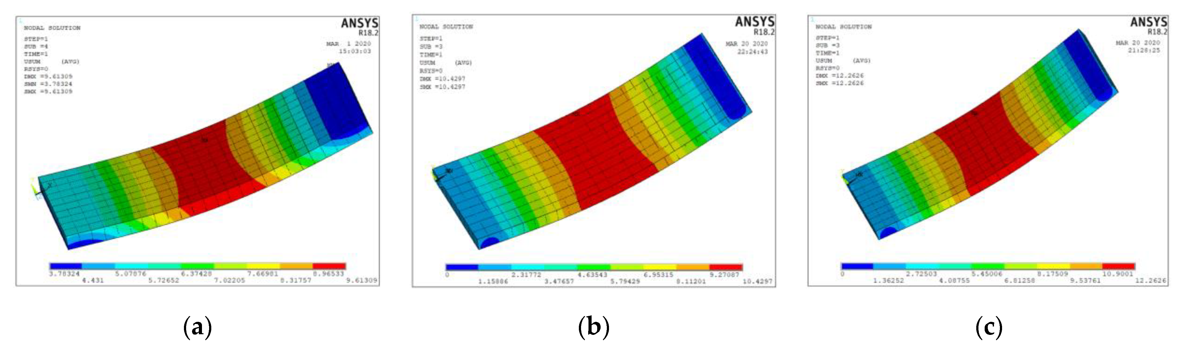
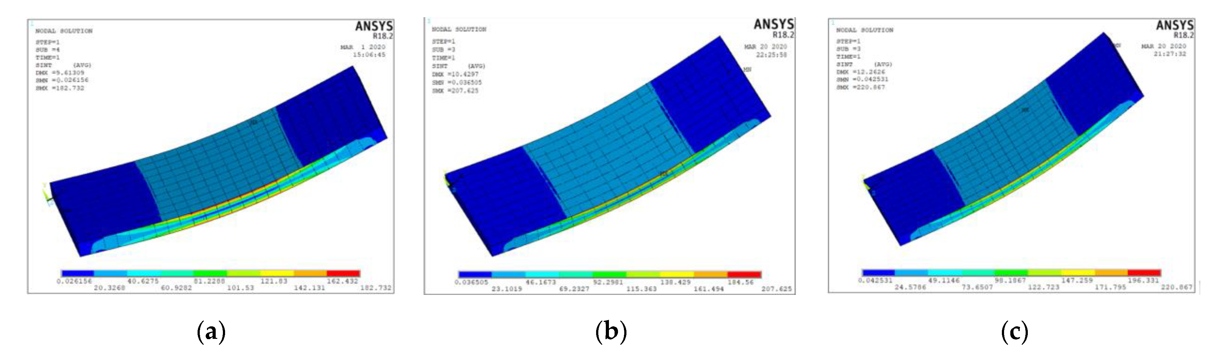
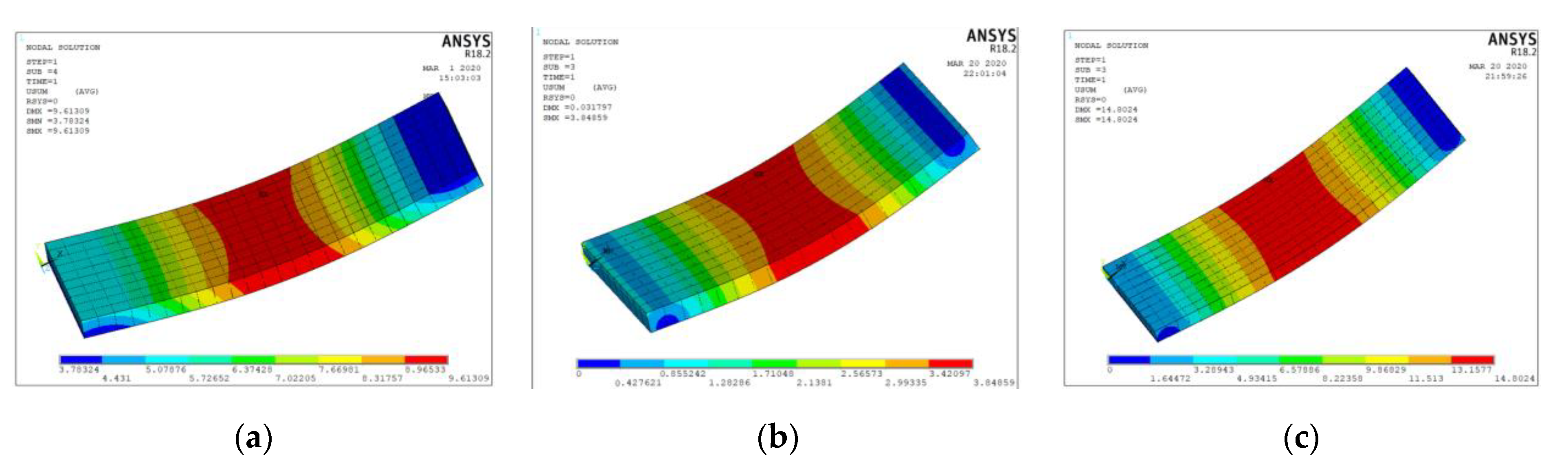
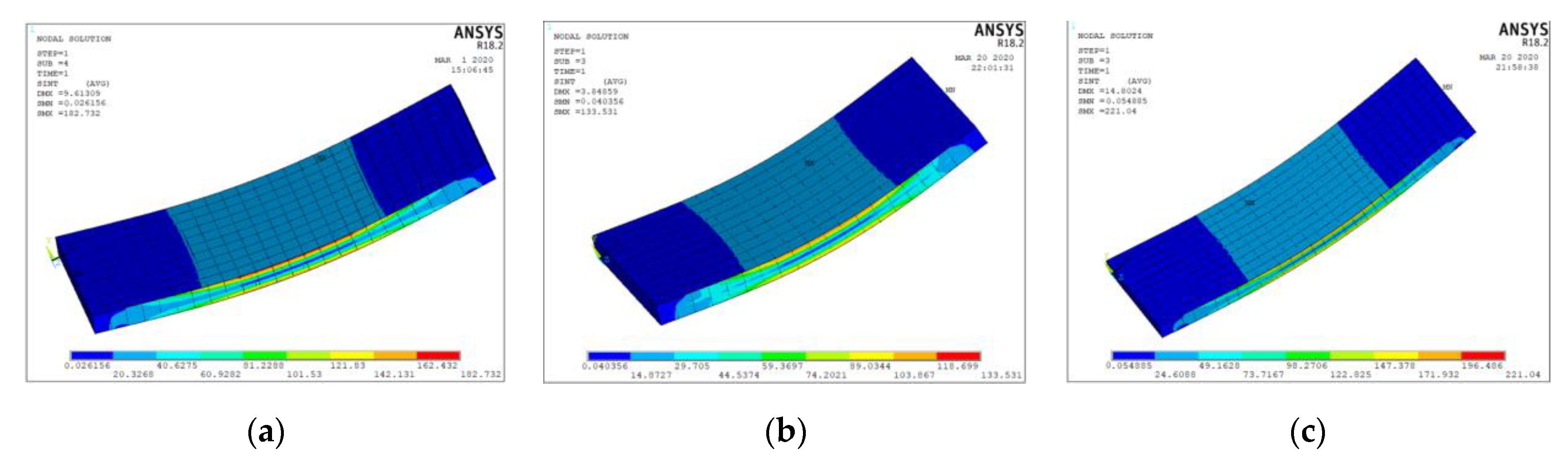
5.3. Analysis of Influencing Factors
6. Conclusions
- (1)
- The multi-cavity steel–concrete composite floor has relatively large bearing capacity, stiffness and good ductility. Moreover, the multi-cavity steel–concrete composite floor has good crack resistance and integrity. The porous steel plates are well bonded with self-compacting concrete to form an integrated structure. The cavity steel plate provides good shear performance for the composite floor, and effectively restricts the horizontal movement of concrete under load, which can ensure that the cavity steel plate and self-compacting concrete work together under loading.
- (2)
- Compared with certain existing precast floors, the total weight of steel used in the multi-cavity steel–concrete composite floor is nearly twice as much as that of certain existing precast floors, but the bearing capacity of multi-cavity steel–concrete composite floor increases to more than four times.
- (3)
- The multi-cavity steel–concrete composite floor is still in the elastic stage when it reaches the limit deflection.
- (4)
- The steel thickness, composite floor thickness, cavity size and span length have a great influence on its bearing capacity. The bearing capacity and section rigidity of composite floor can be improved by increasing steel thickness and floor thickness and by reducing cavity size and floor span length.
Author Contributions
Funding
Acknowledgments
Conflicts of Interest
References
- Pope, K.W. Prefabricated Building Panel. US Patent US3646715, 7 March 1972. [Google Scholar]
- Ji, Y. Survey on the applicable and physical performance of prefabricated panel building. Urban Probl. 2011, 6, 37–42. [Google Scholar]
- Ji, Y. The analysis on the application and physical performance of prefabricated panel building in Beijing. In Proceedings of the International Conference on Information Management, Kunming, China, 26–28 November 2011. [Google Scholar] [CrossRef]
- Shen, K.; Cheng, C.; Li, X.; Zhang, Z. Environmental cost-benefit analysis of prefabricated public housing in Beijing. Sustainability 2019, 11, 207. [Google Scholar] [CrossRef] [Green Version]
- Wu, F.; Deng, L.; Liu, B.; Li, J.; Chen, S. Experimental study on simply supported one-way prestressed two-way reinforced concrete composite floor. Build. Struct. 2014, 44, 6–11. [Google Scholar]
- Liu, Y.; Tong, G.; Li, W.; Shi, C.; Cao, Y. Research on performance test and design method of steel truss composite slab. China Concr. Cem. Prod. 2006, 2, 57–60. [Google Scholar]
- Yao, Z.; Zhang, Z. Study on mechanical properties of steel truss concrete composite floor(I)—Experimental study. In Proceedings of the Industrial Buildings, Beijing, China, 20 June 2018; pp. 73–77. [Google Scholar]
- Yao, Z.; Zhang, Z. Study on mechanical properties of steel truss concrete composite floor(II)—Numerical analysis. In Proceedings of the Industrial Buildings, Beijing, China, 20 June 2018; pp. 78–82. [Google Scholar]
- Li, C.; Guo, F.; Yang, Z.; Zhang, X. Experimental study on flexural capacity of open profiled steel sheet concrete composite floor. Prog. Steel Build. Struct. 2018, 20, 18–23. [Google Scholar] [CrossRef]
- Wang, Q.; Shi, Q.; Li, W. Experimental study on mechanical properties of closed multi cavity steel plate. Build. Struct. 2014, 44, 95–99. [Google Scholar]
- Qiao, W.; Yan, X.; Zhu, R.; Wang, F.; Wang, D. Flexural properties of new cold-formed thin-walled steel and concrete composite slabs. J. Build. Eng. 2020, 31, 101441. [Google Scholar] [CrossRef]
- Tian, L.-M.; Kou, Y.-F.; Hao, J.-P.; Zhao, L.-W. Flexural performance of a lightweight composite floor comprising cold-formed steel trusses and a composite mortar slab. Thin-Walled Struct. 2019, 144, 106361. [Google Scholar] [CrossRef]
- Feng, R.-Q.; Zhu, B.; Xu, P.; Qiu, Y. Seismic performance of cold-formed steel framed shear walls with steel sheathing and gypsum board. Thin-Walled Struct. 2019, 143, 106238. [Google Scholar] [CrossRef]
- Hegyi, P.; Dunai, L. Experimental study on ultra-lightweight-concrete encased cold-formed steel structures Part I: Stability behaviour of elements subjected to bending. Thin-Walled Struct. 2016, 101, 75–84. [Google Scholar] [CrossRef]
- Zhu, X.; Takimoto, K.; Tanaka, H.; Qkubo, N.; Higashiyama, H. Properties of an innovative shear connector in a steel-concrete composite slab. J. Constr. Steel Res. 2020, 172, 106165. [Google Scholar] [CrossRef]
- Marlene, S.; Thomas, P.; Josef, F. Development of an innovative sandwich plate for trough-type railway bridges: Extremely slender deck slab structure in steel-concrete composite design with cellular longitudinal shear connectors. Steel Constr. 2016, 9, 184–190. [Google Scholar]
- Swaminathan, S.; Siva, A.; Senthil, R.; Kinson, P. Experimental Investigation on Shear Connectors in Steel-concrete Composite Deck Slabs. Indian J. Sci. Technol. 2016, 9, 1–8. [Google Scholar] [CrossRef] [Green Version]
- Machado, M.A.S.; Sotelino, E.D.; Liu, J. Modeling Technique for Honeycomb FRP Deck Bridges via Finite Elements. J. Struct. Eng. 2008, 134, 572–580. [Google Scholar] [CrossRef]
- Barros, J.; Pereira, E.; Santos, S. Lightweight Panels of Steel Fiber-Reinforced Self-Compacting Concrete. J. Mater. Civil Eng. 2007, 19, 295–304. [Google Scholar] [CrossRef] [Green Version]
- Wu, Q.; CITIC Construction Co, Ltd. Influence of rheology of paste on the workability of self-compacting concrete. Concrete 2015, 9, 64–68. [Google Scholar]
- Vurst, F.V.D.; Steffen, G.; Schutter, G.D. The Impact of VMA on the Rheology, Thixotropy and Robustness of Self-compacting Mortars. Calcined Clays Sustain. Concr. 2015, 10, 159–167. [Google Scholar]
- National Standards of the People’s Republic of China. Code for Design of Concrete Structures (GB50010-2010); China Architecture & Building Press: Beijing, China, 2010. [Google Scholar]
- Gao, Y.; Liang, X.; Dong, L.; Sun, S.; Li, H.; An, J.; Zhu, L.; Wang, P.; Lu, C.; Yin, J.; et al. Metallic Materials Tensile Test Method at Room Temperature(GB/T 228.1-2010); China Architecture & Building Press: Beijing, China, 2010. [Google Scholar]
- CECs. Code for Design and Construction of Composite Floor (CECS273:2010); China Architecture & Building Press: Beijing, China, 2010. [Google Scholar]
- Cheng, L. Development and Application of Fully Assembled Floor of Steel Structure Residence. Master’s Thesis, Tianjin University, Tianjin, China, 2018. [Google Scholar]
- Nie, J.; Chen, B.; Chen, G.; Guo, Z.; Wei, J. Experimental study on reinforced concrete composite floor. Ind. Build. 2003, 12, 43–46. [Google Scholar]
- Shen, J.; Wang, C.; Jiang, J. Finite Element Analysis of Reinforced Concrete and Limit Analysis of Plate and Shell; Tsinghua University Press: Beijing, China, 1993; pp. 85–110. [Google Scholar]
- Xiong, F.; Li, Z. Structural Design Principle; China Architecture & Building Press: Beijing, China, 2013. [Google Scholar]
- Li, W. Finite Element Analysis of Profiled Steel Sheet Concrete Composite Floor. Master’s Thesis, Lanzhou University of Technology, Lanzhou, China, 2004. [Google Scholar]
- Ye, J.; Mojtabaei, S.M.; Hajirasouliha, I. Local-flexural interactive buckling of standard and optimised cold-formed steel columns. J. Constr. Steel Res. 2018, 144, 106–118. [Google Scholar] [CrossRef]
- Kyvelou, P.; Gardner, L.; Nethercot, D.A. Design of cold-formed steel composite flooring systems with partial shear connection. Ce/papers 2017, 1, 1899–1908. [Google Scholar] [CrossRef]


| Floor Type | Size (mm) | Maximum Bearing Capacity (kN) | Total Weight of Steel (kg) |
|---|---|---|---|
| Multi-Cavity Floor | 2500 × 1000 × 120 | 96.0 | 52.90 |
| Reinforced Concrete Composite Floor | 2500 × 1000 × 120 | 21.6 | 30.20 |
| Precast Anchor Floor | 2500 × 1000 × 120 | 13.6 | 28.19 |
| Number | Steel Thickness (mm) | Floor Thickness (mm) | Cavity Size (mm) | Span Length (mm) | Midspan Deflection (mm) | Maximum Stress of Steel (MPa) |
|---|---|---|---|---|---|---|
| 1 | 1.0 | 120 | 100 | 2500 | 9.61 | 182.7 |
| 2 | 1.5 | 120 | 100 | 2500 | 8.98 | 69.2 |
| 3 | 2.0 | 120 | 100 | 2500 | 8.67 | 66.8 |
| 4 | 1.0 | 110 | 100 | 2500 | 10.43 | 207.6 |
| 5 | 1.0 | 100 | 100 | 2500 | 12.26 | 220.9 |
| 6 | 1.0 | 120 | 100 | 2000 | 3.85 | 133.5 |
| 7 | 1.0 | 120 | 100 | 3000 | 14.80 | 221.0 |
| 8 | 1.0 | 120 | 125 | 2500 | 10.43 | 195.9 |
| 9 | 1.0 | 120 | 250 | 2500 | 12.61 | 199.5 |
Publisher’s Note: MDPI stays neutral with regard to jurisdictional claims in published maps and institutional affiliations. |
© 2020 by the authors. Licensee MDPI, Basel, Switzerland. This article is an open access article distributed under the terms and conditions of the Creative Commons Attribution (CC BY) license (http://creativecommons.org/licenses/by/4.0/).
Share and Cite
Li, C.; Li, G.; Yu, R.; Ma, X.; Qin, P.; Wang, X. Study on Mechanical Properties of Multi-Cavity Steel–Concrete Composite Floor. Appl. Sci. 2020, 10, 8444. https://doi.org/10.3390/app10238444
Li C, Li G, Yu R, Ma X, Qin P, Wang X. Study on Mechanical Properties of Multi-Cavity Steel–Concrete Composite Floor. Applied Sciences. 2020; 10(23):8444. https://doi.org/10.3390/app10238444
Chicago/Turabian StyleLi, Chunbao, Gaojie Li, Rangang Yu, Xiaosong Ma, Pengju Qin, and Xukai Wang. 2020. "Study on Mechanical Properties of Multi-Cavity Steel–Concrete Composite Floor" Applied Sciences 10, no. 23: 8444. https://doi.org/10.3390/app10238444