Article

Assessment of Existing Bond Models for Externally Bonded SRP Composites

Faculty of Civil Engineering, Silesian University of Technology, 44-100 Gliwice, Poland
Appl. Sci. 2020, 10(23), 8593; https://doi.org/10.3390/app10238593
Submission received: 14 November 2020 / Revised: 27 November 2020 / Accepted: 27 November 2020 / Published: 30 November 2020
(This article belongs to the Special Issue Advances in Design, Repair and Materials of Structural Concrete)

Abstract

:

Featured Application

The results presented in the manuscript may be helpful for designers in choosing the most appropriate bond model for SRP composites.

Abstract

This manuscript assessed the applicability of the existing ultimate bond formulas originally developed for externally bonded carbon fiber-based composites in the analysis of steel-reinforced polymers (SRPs). In the first part, the methods of predicting the bond capacity are reviewed, the differences are indicated, and the factors determining the bond are discussed; then, using the bond test results of over 400 samples available in the literature, the bond prediction methods are assessed by graphical comparison. The evaluation mainly concerned concrete elements and epoxy adhesives; however, to a lesser extent, a similar analysis was performed for the masonry substrate and grout matrices. The results showed the relatively good applicability of the majority of bond prediction models for the analysis of SRP composites. In most cases, the ultimate bond force was slightly underestimated, which was beneficial in the design of this type of strengthening. Larger discrepancies concerned weaker grout matrices.

1. Introduction

Strengthening of structures with externally bonded reinforcement is nowadays the most popular method of restoring or improving the bearing capacity. The most popular in the construction industry are organic fibers, especially glass and carbon. For this reason, most of the standards and design methods have been developed based on research on these types of composites. This is a barrier to popularizing alternative, often equally effective and cheaper solutions [1]. An example is ultra-high tensile steel (UHTS) and textile composites that use it. They were placed on the market in 2004. Most of the first applications of these composites, mainly in the USA and Italy, are related to the work of research teams developed in these two countries [2,3,4,5]. Their research allowed for the dissemination of engineering knowledge necessary for the practical applications of steel-reinforced composites [6].
A modern structural engineer expects clear guidelines, manuals, and design standards. Such international and local documents can be found for carbon fiber reinforced polymer (CFRP) composites. This paper aims to answer, at least partially, the question of whether they can be used in the design of steel-reinforced polymer (SRP) strengthening. The comparison of the mechanical properties showed many similarities. Due to the high carbon content and drawing down to diameters of 0.20–0.35 mm, the tensile strength of pure steel cord is around 3000 MPa. Additionally, the modulus of elasticity is comparable (around 180–210 GPa). The differences appear in the fabrication method. CFRP composites can be made as strips, by a pultrusion process, and then adhered to the substrates, or as textiles. SRP composites are always textiles that are fixed in a wet lay-up process. Fiber volume fraction in the pre-cured laminate is significantly greater; therefore, CFRP strips maintain the properties of the fibers. The strength and stiffness of the SRP related to the cross-section of the finished laminate can drop by more than three times [7], depending on the density of the cord and the amount of resin used. Both compared materials retain almost constant stiffness throughout the load range, although in the case of SRP composites, a short inelastic branch can be seen [8]; therefore, their fracture strain is about 50% greater [7].
The question is, how described differences affect the behavior of strengthened specimens. The analysis provided by Papakonstatntinou et al. [9] proved that in the case of flexural behavior, existing codes could be successfully used; however, in the case of SRP composites, the safety margin was significantly lower. It should be noted here that a structural element strengthened with an externally bonded composite usually exhibits forms of failure unknown for normal reinforced concrete. It could be a fracture of the fibers, or more commonly, debonding of the composite. Mitolidis et al. [8] showed clear differences in the bond strength and debonding slip. Proper modeling of debonding seems to be a key to the correct design of SRP strengthening. This manuscript assessed the existing strength anchorage models by testing them on a wide range of laboratory test results. The conclusions can be used in practice to select the safest and most accurate method of predicting the bond of SRP overlays.

2. Bond Performance of External Strengthening

Debonding can be defined as a brittle loss of adhesion between composite overlay and substrate. This is the most common failure mode of externally bonded fiber-reinforced strengthening systems. Existing design guidelines distinguish between four models of debonding. Originally, they were defined by Teng et al. [10]. Those are plate end interfacial debonding, concrete cover separation, intermediate flexural crack-induced debonding, and critical diagonal shear crack-induced debonding. Schematically they are presented in Figure 1. In the case of SRP composites, what can also occur is interlaminar failure at the matrix–fiber interface [11].
Bond performance may be determined in double-shear, single-shear, and notched beam test. In the first two cases, depending on how the force is applied, there can be an indicated push-shear test and pull-shear test. In the push-shear test, clamping the sample is easier; therefore, it is more popular. However, the pull-shear test better reflects the real conditions under which debonding occurs along the tensed surface.
Bond performance is influenced by many factors related to geometry, mechanical properties of materials, environmental conditions, and application conditions. Design methods take into account only some of them. Undoubtedly, the most important factor is the bond area expressed by bond width and bond length. Some bond-strength models introduce the upper limit of the real bond length (called effective bond length) beyond which no further increase in bond force occurs. The second important geometric parameter is the thickness of the composite. The real thickness includes the fibers and the epoxy matrix. Its direct adoption into the calculations could limit their comparability for SRP tapes of different densities; therefore, the thickness should be taken as the dimension of the cross-sectional area of the fibers distributed over the width of the composite.
The debonding of an SRP composite usually occurs at a thin layer beneath the concrete surface, sometimes with local removal of cover pieces. Concrete is usually the weakest material in a joint; therefore, its strength is another critical factor affecting the bond strength. Typically, compressive strength needs to be determined, less often tensile strength or surface tensile strength. Composite mechanical properties also affect the bond strength. In general, the higher stiffness, the better bond.
The bond strength models are most commonly classified into three categories [12,13]:
  • Empirical models, based on the regression of test data, such as Tanaka [14], Hiroyuki and Wu [15], and Maeda [16].
  • Fracture mechanics based models, including Taljsten [17], Niedermeier [18], Neubauer and Rostassy [19], Yuan and Wu [20], and Lu et al. [21].
  • Design models, usually based on simple assumption, such as Dai et al. [22] Brosens and van Germet [23], Khalifa et al. [24], Yang et al. [25], Adhikary and Mutsuyoshi [26], Sato et al. [27], Chen and Teng [28], DeLorenzis et al. [29], Seracino et al. [30], and Camli and Binici [31].
The length of the anchorage seems to be of key importance for the bearing capacity of the bonded joint. As was earlier mentioned, experimental studies and some fracture mechanics analyses showed that above a certain length (called effective or active bond length), the further increase in load capacity was negligible. To indicate this phenomenon, Toutanji et al. [32] proposed an alternative classification for models independent of the bond length, models not considering the effective bond length, and models considering the effective bond length.
The models analyzed in the article were sorted according to the first classification and summarized in Table 1. Some of these theoretical models have been developed and included in technical guidelines for the design of externally bonded FRP composites. Their examples were also included in the comparisons presented in this manuscript. The design procedures used therein are described in Table 2.
The following technical standards were considered: British TR55/2000 [33], international fib Bulletin 14/2001 [34], Japan JCI 2003 [35], Swiss Code SIA 166/2004 [36], Italian standard CNR-DT200R1/2013 [37], and the newest international fib Bulletin 90/2019 [38].

3. Laboratory Test Database

The design methods presented in Table 1 and Table 2 were developed for a wide range of FRP composites, based not only on carbon fibers but also on glass, aramid, and basalt fibers. Some of the design parameters and coefficients used in these documents were determined and calibrated on a wide spectrum of laboratory tests. SRP composites, as newer material, have not been studied so widely. Previous attempts to assess the suitability of formulas for determining the bond of SRPs included the own research of authors [39,40] or were carried out on a relatively small number of samples and prediction models [8].
The database used for the comparison in this work consisted of 434 debonding tests. The data were collected from 11 experimental campaigns reported in the literature, including independently analyzed tests of steel-reinforced epoxy polymers bonded to concrete (237 samples [39,41,42,43,44,45]), and masonry (114 samples [46,47,48,49]), and steel-reinforced grout (SRG) bonded to concrete (83 samples [50]). Table 3 summarizes the main geometric and material data available in the research reports used, as well as the corresponding reference and the number of tested specimens. In some of the test reports, tensile strength was not specified. In this case, it was calculated as:
f c t m = 0.3 ( f c m 8 ) 2 / 3 ,
Most of the samples were tested in a single [39,44,45,46,49,50] and double [42,43,46,48,49] push-shear test, only Figeys [41] used the double pull-shear method. To reflect the test conditions, all the material properties and correction coefficients taken during the calculations were based on mean values. In the case of the CNR-DT200R1/13 standard, a different value of the kG corrective factor for concrete (0.077 mm) and masonry (0.093 mm) was taken into account.

4. Results and Discussion

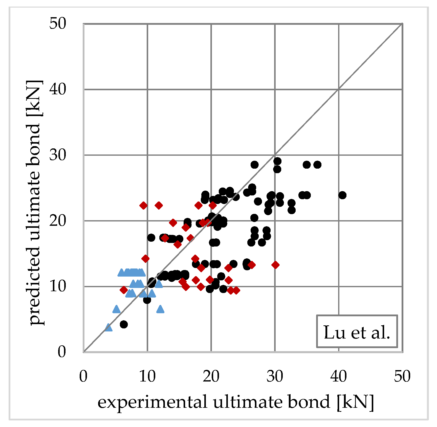
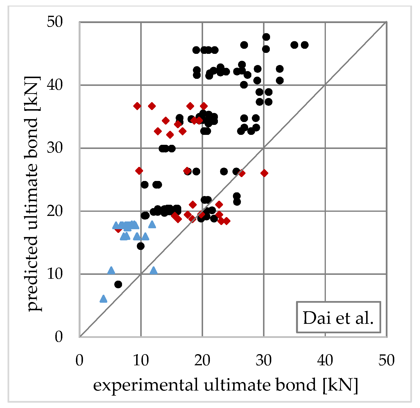
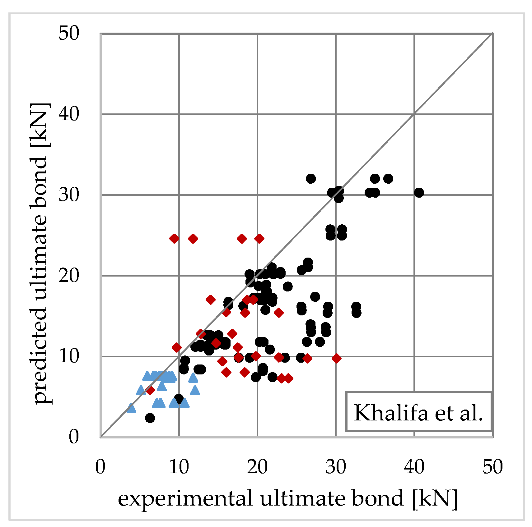
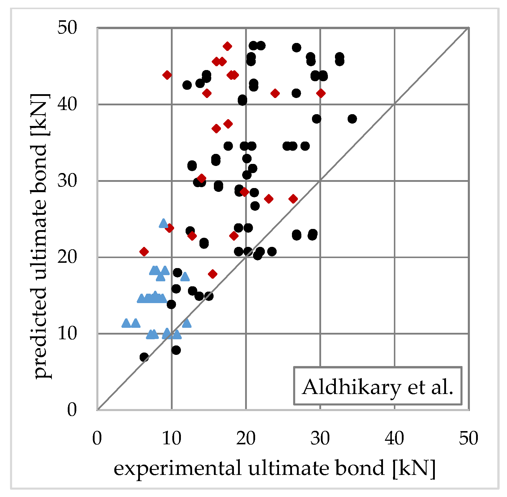
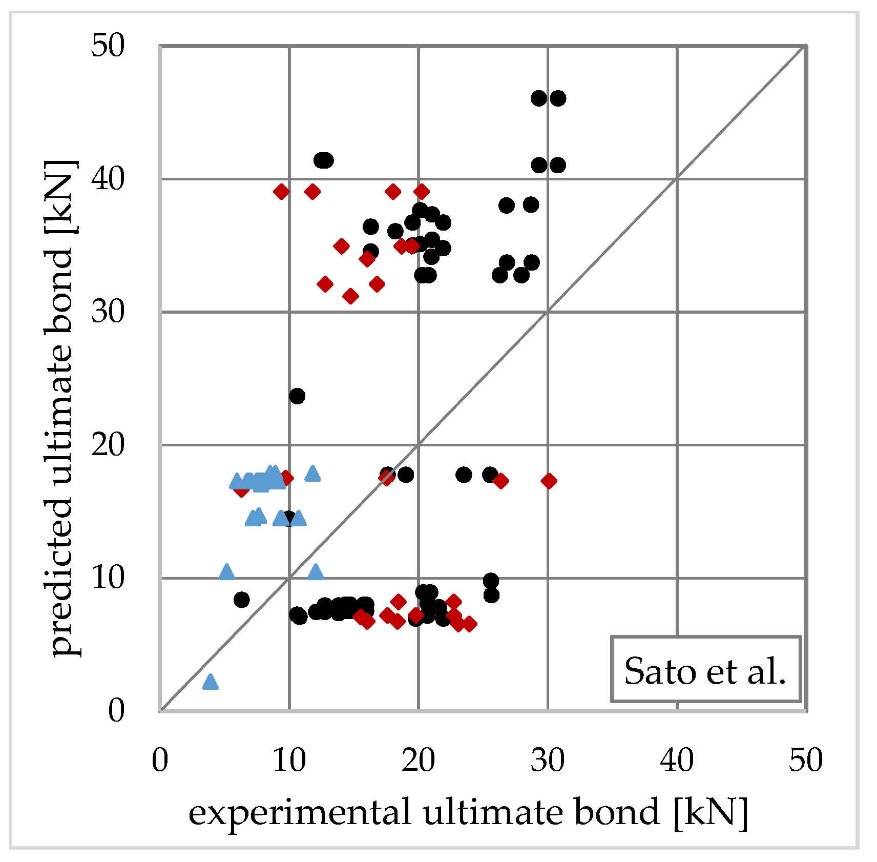
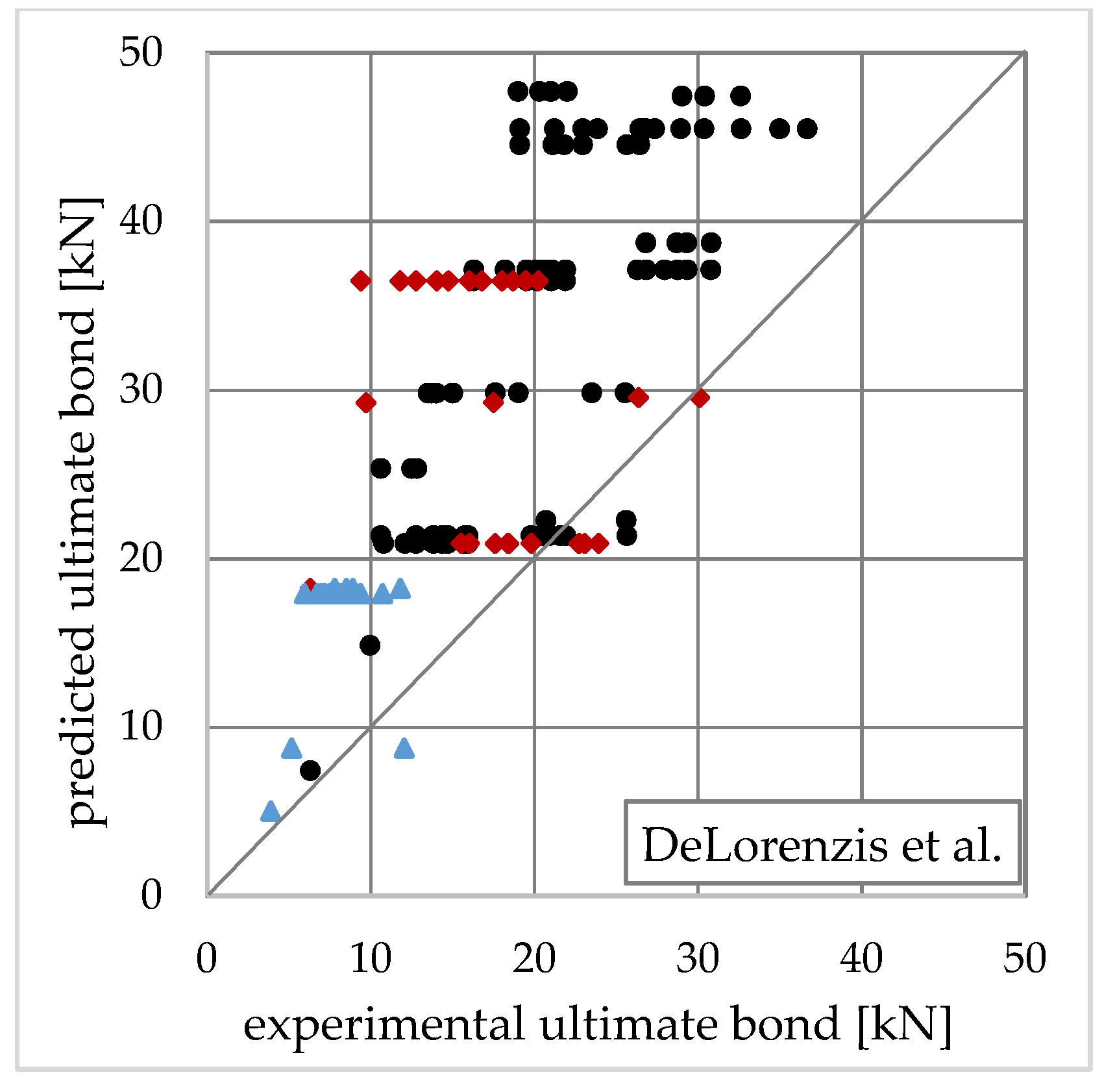
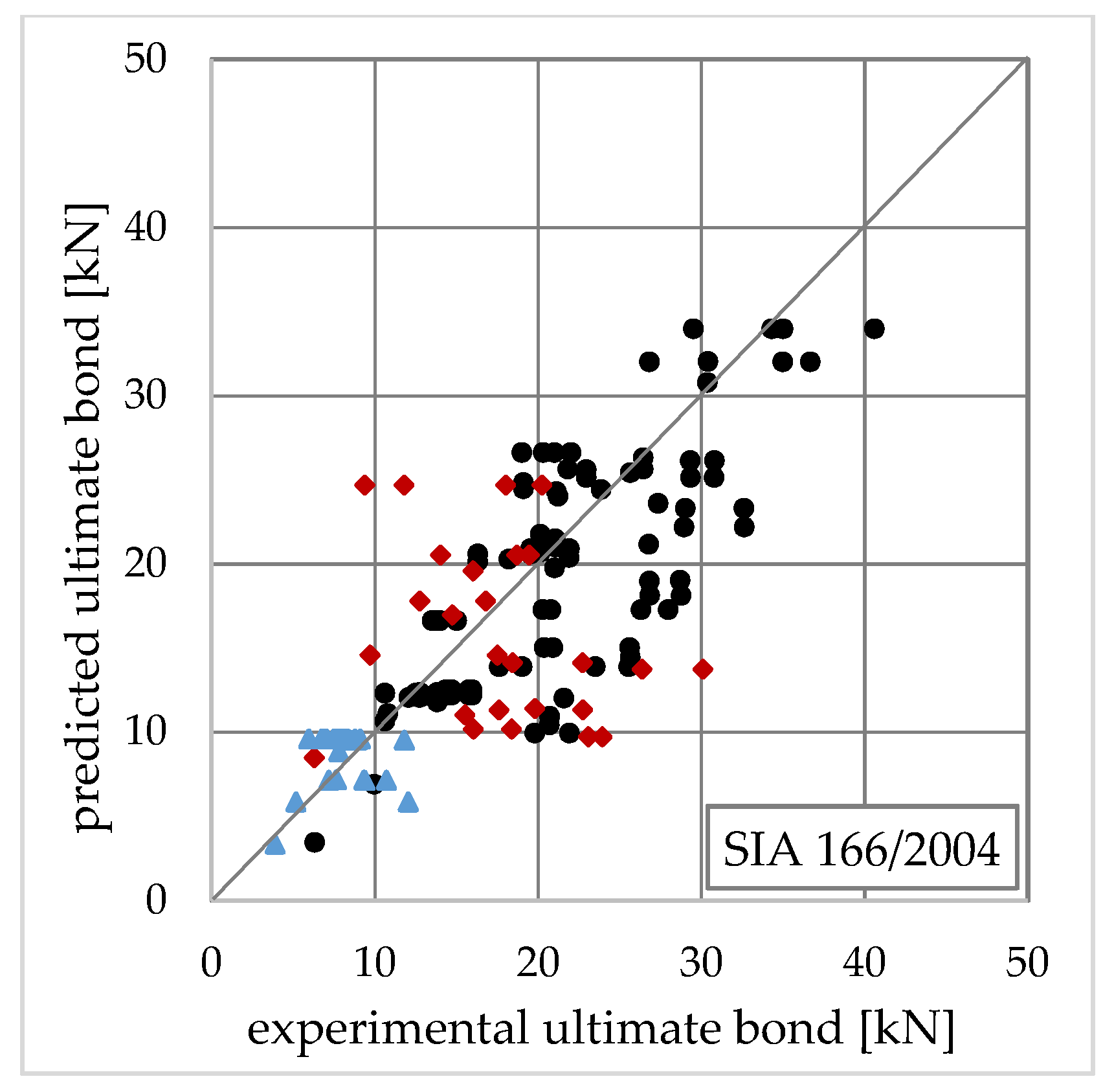
The graphical comparison of bond models is shown in Figure 2, Figure 3, Figure 4, Figure 5, Figure 6, Figure 7, Figure 8, Figure 9, Figure 10, Figure 11, Figure 12, Figure 13, Figure 14, Figure 15, Figure 16, Figure 17, Figure 18, Figure 19, Figure 20, Figure 21, Figure 22, Figure 23, Figure 24 and Figure 25 in the order of their presentation in Table 1 and Table 2. The types of substrate and adhesive are distinguished by other markers. For SRP composites bonded to concrete, it is Applsci 10 08593 i001, for masonry, it is the sign Applsci 10 08593 i002, and for SRG tapes, it is Applsci 10 08593 i003.
Each graph contains a bisector. The point on this line corresponds to the perfect agreement of the prediction model with the tests. The points below the line indicate that the model underestimated the experiment. This group of results can be considered safe. The points above the bisector mean that the model overestimated the test result and was therefore unsafe.

4.1. Comparison of Models

The first feature visible in the graphs is the scattering of results. The more they were concentrated around the bisector, the more accurate the model. In this respect, the best models were Lu et al. [21] and the newer Chen and Teng [28], Seracino et al. [30], as well as Camli and Binici [31].
The largest dispersion of results concerned the Dai et al. [22], Brosens and van Germet [23], and Adhikari and Mitsuyoshi [26] models. The common feature of the three models was that they did not depend on the anchorage length or the effective anchorage length. This proved the importance of this quantity in the analysis. The Tajlsten [17] model was an exception in this respect.
Another interesting observation concerned the Tanaka [14] and Hiroyuki and Wu [15] models. They undervalued the predicted bond for higher values of an experimentally obtained ultimate bond. This may have resulted from the omission of the concrete strength in the analysis that characterized these two models.
Dai et al. [22], Adhikary and Mitsuyoshi [26], and DeLorenzis et al. [29] were among the models that overestimated the bond capacity. The DeLorenzis model was calibrated on bond tests of CFRP sheets, and this may be the reason for its characteristics. Interesting in this regard are the results based on the Sato et al. model [27] (Figure 15). It underestimated the bond capacity in terms of low forces and, at the same time, dangerously overestimated for higher forces. Groups of models that underestimated the bond included Taljsten [17], Yuan and Wu [20], Khalifa et al. [24], Yang et al. [25], and the British TR55/2000 standard [33].
The described graph observations were confirmed by the results of the statistical analysis presented in Table 4, Table 5 and Table 6. The following parameters were used to evaluate and were analyzed in the manuscript bond prediction models: mean value of the predicted, theoretically to measure experimentally bond strength ratio ( F u b , p r e d i c t e d / F u b , t e s t ), standard deviation (SD), and Pearson’s correlation coefficient (PCC). Additionally, to evaluate the safety of the prediction, the percentage of results was given. Parameters are listed separately for the SRP bonded to concrete (Table 4), SRP bonded to masonry (Table 5), and SRG bonded to concrete (Table 6).
In the group of SRP models bonded to concrete, the mean closest to 1.0 can be found in the Brosens and van Germet [23], and Neubauer and Rostasy [19] models; however, it was accompanied by one of the highest standard deviations and correlation coefficients. In this situation, a good agreement of the mean should be considered as aleatory.
Furthermore, after analyzing the values of all statistical parameters, we found that Lu et al. [21] and Chen and Teng [28] models were the most accurate. Similarly, among the technical guidelines, fair exactness ensured JCI 2003, SIA 166/2004, CNR-DT200R1/13, and the fib bulletin 90/2019; they could be successfully used to predict the bond strength of SRP composites to concrete. The older fib bulletin 14/2001 and especially TR55/2000, tended to underestimate the bond capacity too much.
Models by Dai et al. [22], Adhikary and Mitsuyoshi [26], Sato et al. [27], and DeLorenzis [29] not only overestimated the bond prediction but also had a very high percentage of unsafe design.
As shown in Table 5, the general trend for masonry-bonded SRP composites was similar to that for concrete-bonded. Similar models tended to overestimate or underestimate prediction. However, a general increase in the mean of the ratio of predicted to experimentally measured results could be observed. It ranged from one (Tajlsten [17], Yuan and Wu [20]) to several dozen percent (Tanaka [14], fib Bulletin 14/2001 [34], and CNR-DT 200 [37]). Only two models showed a decrease in the mean value (Adhikary and Mutsuyoshi [26] and Sato et al. [27]); however, they still overestimated the bond strength, and the result was characterized by the highest standard deviation.
Against the background of all the results in Table 5, the prediction error of the Italian Standard CNR-DT200R1/13 may be surprising. Average predictions increased by more than 50%. It results most likely from assuming an overestimated value of the kG coefficient. Based on Appendix D of the cited standard, it was adopted as a mean value kG = 0.093 mm, but it was characterized by high variation (recommended for design, 5% fractile is 0.031 mm).
Evaluating only the mean parameter presented in Table 6, the assessment of the possibility of using the analyzed models in predicting the SRG bond would be similar to the SRP. However, a large standard deviation, and especially the negative correlation coefficient, excluded the applicability of those models. The analysis of the experimental measures used for the comparison showed their low sensitiveness to the strength of concrete. This may be due to significantly worse properties of grout adhesives compared to epoxies. Under these conditions, delamination may occur in the adhesive layer. The adhesive was the weakest element, and its strength properties determined the bond capacity. None of the analyzed models in this manuscript took into account the properties of the adhesive, and this may have caused a large dispersion of the results.

4.2. Precision of Predictions Compared to CFRP Composites

The accuracy of the prediction models for SRP bonded to concrete was not any less than that for CFRP composites. Table 7 shows a comparison of prediction error for selected models (according to mean ratios given in Table 4) and is available in the literature results of similar assessments for CFRP strips. In most cases, the differences did not exceed ten percentage points, and for the previously favored models, Lu et al. [21] and Chen and Teng [28] were practically identical. Similarly to the SRP, can be found models that tended to overestimate and underestimate the results. This proved that SRP and CFRP composites were very similar in terms of bond strength.

4.3. Assessment of Design Guidelines

To evaluate the reliability of design guidelines for the bond prediction of SRP, a demerit points classification proposed by Collins [53] was used. This scale allowed considering the safety and accuracy of design procedures by weighting the ratio between the ultimate bond strength, estimated theoretically and measured experimentally ( F u b , p r e d i c t e d / F u b , t e s t ). Table 8 presents the classification adopted in this study based on the original values proposed by Collins.
The results of bond comparisons were classified into appropriate categories, as shown in Table 8, and the products were then multiplied by the appropriate demerit points classification (DPC) and summed up. The number of results assigned to the categories and the summed DPC is shown in Table 9 and Table 10. A lower overall DPC means that the model under consideration was more reliable.
In the case of SRP bonded to concrete, the lowest total demerit points (111 points) presented the Swiss Standard SIA 166/2004. Fib bulletin 14 achieved a slightly worse result (115 points); however, this was mainly due to a small number of overestimated results. In terms of the number of the most accurate predictions, there were SIA166, Italian code CNR-DT200, and fib bulletin 90.
Among the prediction guidelines concerning the SRP bonded to masonry, the lowest number of demerit points was obtained by the British standard TR55/20000 (28 points). Taking into account its strong tendency to lower the results (shown in Table 5), the Swiss Standard SIA 166/2004 should be assessed higher, despite the significantly higher number of demerit points (78 points). The Italian Standard CNR-DT200 was the most unfavorable in this comparison, mainly due to the previously described problem of overestimated correction factor kG.

5. Conclusions

Although all evaluated models were developed for composites reinforced with organic (mainly carbon and glass) fibers, the obtained results of comparisons showed surprisingly good compatibility for ultra-high-strength steel textile composites.
Most of the assessed models should be considered moderately conservative, with the ratio of predicted to experimental bond strength in the range of 0.5–0.85. As shown in Table 7, this trend also applied to CFRP composites, and in most comparisons, the results obtained for SRP can be assessed as more accurate.
The best accuracy was guaranteed by Lu et al.’s proposal, [21] Chen and Teng’s proposal [28], and technical guidelines recommendations (except TR55/2000 [33]). This proved the predominance of models calibrated on a very large number of different samples.
Among all the analyzed models, there were proposals whose results differed significantly from the test results. In a few cases, the predicted to experimental bond strength ratio exceeded the risky limit of 1.15. The worst and most unsafe were the proposals of Dai et al. [22], Adhikari and Mitsuyoshi [26], Sato et al. [27], and De Lorenzis et al. [29]. These models should not be used to determine the bond strength of SRP composites.
The highest compliance was obtained in the analysis of SRP composites bonded to concrete. This was because most of the tested models were developed for epoxy-bonded concrete strengthening systems. In the case of bonding to masonry, the predicted to experimental bond strength ratios were several percentage points higher. Nevertheless, most of the analyzed models could still be considered safe. Apart from the previously mentioned, the Maeda et al. [16], Brosens and van Germet [23], and Camli and Binici [31] models should not be used in this case.
The classification of technical guidelines with the use of the DPC scale as the most universal, distinguished the Swiss standard SIA166/2004 [36] and the latest fib bulletin 90/2019 [39]. The TR55/2000 [33] guideline seemed too conservative. The Italian standard CNR-DT200R1/13 [37], in the case of masonry substrate, estimated too many results classified as dangerous. Perhaps this was the effect of taking the overestimated value of the kG coefficient in the analysis.
The last conclusion concerned SRG composites. The results obtained from the analysis were inconclusive. They should be extended to a larger experimental database.

Funding

This research was funded by Silesian University of Technology, grant BK-298/RB6/2020.

Conflicts of Interest

The author declares no conflict of interest.

Nomenclature

b (mm)concrete width
b f (mm)FRP (SRP) width
E c (MPa)elastic modulus of concrete
E f (MPa)elastic modulus of composite (along fibers)
f c , f c m (MPa)concrete compressive strength
f c t m (MPa)concrete tensile strength
F u d (N)debonding force
G f (MPa·mm)fracture energy
L b (mm)bond length
L e (mm)effective bond length
k b , β p , β w geometrical parameter
t c (mm)concrete thickness
t f (mm)FRP (SRP) composite thickness
α T , α Y stiffness ratio
τ f (MPa)bond strength

References

  1. Borri, A.; Castori, G.; Corradi, M.; Speranzini, E. Durability Analysis for FRP and SRG Composites in Civil Applications. Key Eng. Mater. 2015, 624, 421–428. [Google Scholar] [CrossRef]
  2. Barton, B.; Wobbe, E.; Dharani, L.R.; Silva, P.; Birman, V.; Nanni, A.; Alkhrdaji, T.; Thomas, J.; Tunis, G. Characterization of reinforced concrete beams strengthened by steel reinforced polymer and grout (SRP and SRG) composites. Mater. Sci. Eng. A 2005, 412, 129–136. [Google Scholar] [CrossRef]
  3. Casadei, P.; Nanni, A.; Alkhrdaji, T.; Thomas, J. Performance of Double-T Prestressed Concrete Beams Strengthened with Steel Reinforced Polymer. Adv. Struct. Eng. 2005, 8, 427–442. [Google Scholar] [CrossRef]
  4. Huang, X.; Birman, V.; Nanni, A.; Tunis, G. Properties and potential for application of steel reinforced polymer and steel reinforced grout composites. Compos. Part B 2005, 36, 73–82. [Google Scholar] [CrossRef]
  5. Prota, A.; Tan, K.Y.; Nanni, A.; Pecce, M.; Manfredi, G. Performance of Shallow Reinforced Concrete Beams with Externaly Bonded Steel-Reinforced Polymer. ACI Struct. J. 2006, 103, 163–170. [Google Scholar]
  6. Lopez, A.; Galati, N.; Alkhrdaji, T.; Nanni, A. Strengthening of a reinforced concrete bridge with externally bonded steel reinforced polymer (SRP). Compos. Part B Eng. 2007, 38, 429–436. [Google Scholar] [CrossRef]
  7. Rizkalla, S.; Rosenboom, O.; Miller, A.; Walter, C. Value Engineering and Cost Effectiveness of Various Fiber Reinforced Polymer (FRP) Repair Systems; Technical Report; Department of Civil Engineering, North Carolina State University Raleigh: Raleigh, NC, USA, 2007. [Google Scholar]
  8. Mitolidis, G.J.; Salonikios, T.N.; Kappos, A.J. Mechanical and Bond Characteristics of SRP and CFRP Reinforcement—A Comparative Research. Open Constr. Build. Technol. J. 2008, 2, 207–216. [Google Scholar] [CrossRef] [Green Version]
  9. Papakonstantinou, C.G.; Kakae, C.; Gryllakis, N. Can Existing Design Codes Be Used to Design Flexural Reinforced Concrete Elements Strengthened with Externally Bonded Novel Materials? IOP Conf. Ser. Mater. Sci. Eng. 2018, 371, 131–142. [Google Scholar] [CrossRef] [Green Version]
  10. Teng, J.G.; Chen, J.F.; Simth, S.T.; Lam, L. FRP-Strengthened RC Structures; John Wiley & Sons Ltd.: Chichester, UK, 2002. [Google Scholar]
  11. Santandrea, M.; Focacci, F.; Mazzotti, C.; Ubertini, F.; Carloni, C. Determination of the interfacial cohesive material law for SRG composites bonded to a masonry substrate. Eng. Fail. Anal. 2020, 111, 104322. [Google Scholar] [CrossRef]
  12. Monaldo, E.; Nerillia, F.; Vairo, G. Effectiveness of some technical standards for debonding analysis in FRPconcrete systems. Compos. Part B 2019, 160, 254–267. [Google Scholar] [CrossRef]
  13. Hosseini, A.; Mostofinejad, D. Effective bond length of FRP-to-concrete adhesively-bonded joints: Experimental evaluation of existing models. Int. J. Adhes. Adhes. 2014, 48, 150–158. [Google Scholar] [CrossRef]
  14. Tanaka, T. Shear Resisting Mechanism of Reinforced Concrete Beams with CFS as Shear Reinforcement. Graduation Thesis, Hokkaido University, Kitaku, Japan, 1996. [Google Scholar]
  15. Hiroyuki, Y.; Wu, Z. Analysis of debonding fracture properties of CFS strengthened member subject to tension. In Proceedings of the 3rd International Symposium on Non-Metallic (FRP) Reinforcement for Concrete Structures, Japan Concrete Institute, Sapporo, Japan, 14–16 October 1997; pp. 287–294. [Google Scholar]
  16. Maeda, T.; Asano, Y.; Sato, Y.; Ueda, T.; Kakuta, Y. A study on bond mechanism of carbon fiber sheet. In Proceedings of the 3rd International Symposium on Non-Metallic (FRP) Reinforcement for Concrete Structures, Japan Concrete Institute, Sapporo, Japan, 14–16 October 1997; pp. 279–285. [Google Scholar]
  17. Taljsten, B. Strengthening of concrete prisms using the plate bonding technique. Int. J. Fract. 1996, 82, 253–266. [Google Scholar] [CrossRef]
  18. Niedermeier, R. Stellungnahme zur Richtlinie für das Verkleben von Beton-bauteilen durch Ankleben von Stahllaschen. Schreiben 1390 vom 30.10.1996 des Lehrstuhls für Massivbau; Technische Universität München: Munich, Germany, 1996. [Google Scholar]
  19. Neubauer, U.; Rostasy, F.S. Design aspects of concrete structures strengthened with externally bonded CFRP plates. In Proceedings of the 7th International Conference on Structural Faults and Repairs, ECS, Edinburgh, Scotland, 8 July 1997; pp. 109–118. [Google Scholar]
  20. Yuan, H.; Wu, Z. Interfacial fracture theory in structures strengthened with composite of continuous fiber. In Proceedings of the Symposium of China and Japan: Science and Technology of the 21st Century, Tokyo, Japan, 13–15 September 1999; pp. 142–155. [Google Scholar]
  21. Lu, X.Z.; Teng, J.G.; Ye, L.P.; Jiang, J.J. Bond-slip models for FRP sheets/plates bonded to concrete. Eng. Struct. 2005, 27, 920–937. [Google Scholar] [CrossRef]
  22. Dai, J.; Ueda, T.; Sato, Y. Development of the nonlinear bond stress–slip model of fiber reinforced plastics sheet–concrete interfaces with a simple method. J. Compos. Constr. 2005, 9, 52–62. [Google Scholar] [CrossRef] [Green Version]
  23. Brosens, K.; van Gemert, D. Anchoring stresses between concrete and carbon fiber reinforced laminates. In Proceedings of the 3rd International Symposium Non-Metallic (FRP) Reinforcement for Concrete Structures, Japan Concrete Institute, Sapporo, Japan, 14–16 October 1997; pp. 271–278. [Google Scholar]
  24. Khalifa, A.; Gold, W.J.; Nanni, A.; Aziz, A. Contribution of externally bonded FRP to shear capacity of RC flexural members. J. Compos. Constr. 1998, 2, 195–202. [Google Scholar] [CrossRef] [Green Version]
  25. Yang, Y.X.; Yue, Q.R.; Hu, Y.C. Experimental study on bond performance between carbon fibre sheets and concrete. J. Build. Struct. 2001, 22, 36–42. [Google Scholar]
  26. Adhikary, B.B.; Mutsuyoshi, H. Study on the bond between concrete and externally bonded CFRP sheet. In Proceedings of the 6th International Symposium on Fiber Reinforced Polymer Reinforcement for Concrete Structures (FRPRCS-5), Cambridge, UK, 16–18 July 2001; pp. 371–378. [Google Scholar]
  27. Sato, Y.; Asano, Y.; Ueda, T. Fundamental study on bond mechanism of carbon fiber sheet. Concr. Libr. Int. JSCE 2001, 37, 97–115. [Google Scholar]
  28. Chen, J.F.; Teng, J.G. Anchorage strength models for FRP and steel plates bonded to concrete. J. Struct. Eng. 2001, 127, 784–791. [Google Scholar] [CrossRef]
  29. De Lorenzis, L.; Miller, B.; Nanni, A. Bond of fiber-reinforced polymer laminates to concrete. ACI Mater. J. 2001, 98, 256–264. [Google Scholar]
  30. Seracino, R.; Raizal Saifulnaz, M.R.; Ohlers, D.J. Generic debonding resistance of EB and NSM plate-to-concrete joints. J. Compos. Constr. 2007, 11, 62–70. [Google Scholar] [CrossRef]
  31. Camli, U.S.; Binici, B. Strength of carbon fiber reinforced polymers bonded to concrete and masonry. Constr. Build. Mater. 2007, 21, 1431–1446. [Google Scholar] [CrossRef]
  32. Toutanji, H.; Saxena, P.; Zhao, L.; Ooi, T. Prediction of Interfacial Bond Failure of FRP–Concrete Surface. J. Compos. Constr. 2007, 11, 427–436. [Google Scholar] [CrossRef]
  33. Darby, A.; Ibell, T.; Clarke, J. TR55 Design Guidance for Strengthening Concrete Structures using Fibre Composite Materials; Concrete Society: Camberley, UK, 2000. [Google Scholar]
  34. Triantafillou, T.; Mathys, S.; Audenaert, K.; Balazs, G.; Blaschko, M.; Blontrocki, H.; Czaderski, C.; David, E.; Di Tomaso, A.; Duckett, W.; et al. fib Bulletin 14. Externally Bonded FRP Reinforcement for RC Structures; Fédération internationale du béton (fib): Lausanne, Switzerland, 2001; p. 138. [Google Scholar]
  35. JCI. Japan Concrete Institute. Technical report of technical committee on retrofit technology. In Proceedings of the International Symposium on Latest Achievement of Technology and Research on Retrofitting Concrete Structures, Kyoto, Japan, 14–15 July 2003. [Google Scholar]
  36. SIA. SIA Norm 166. Klebebewehrung; Schweizerischer Ingenieur- und Architekten-Verein: Zurich, Switzerland, 2004; p. 44. [Google Scholar]
  37. Aiello, M.A.; Ascione, L.; Baratta, A.; Bastanini, F.; Battista, U.; Benedetti, A.; Berardi, V.P.; Bilotta, A.; Borri, A.; Briccoli Bati, S.; et al. Guide for the Design and Construction of Externally Bonded FRP Systems for Strengthening Existing Structures; CNR-DT 200 R1; CNR Advisory Committee on Technical Recommendations for Construction: Rome, Italy, 2013; 152p. [Google Scholar]
  38. Matthys, S.; Triantafillou, T.; Balazs, G.; Barros, J.; Bilotta, A.; Bournas, D.; Ceroni, F.; Czaderski, C.; D’Antino, T.; Kolyvas, C.; et al. fib Bulletin 90. Externally Applied FRP Reinforcement for Concrete Structures; Fédération Internationale du Béton (fib): Lausanne, Switzerland, 2019; 229p. [Google Scholar]
  39. Ascione, F.; Napoli, A.; Realfonzo, R. Experimental and analytical investigation on the bond of SRP systems to concrete. Compos. Struct. 2020, 242. [Google Scholar] [CrossRef]
  40. Ascione, F.; Lamberti, M.; Napoli, A.; Razaqpur, G.; Realfonzo, R. An experimental investigation on the bond behavior of steel reinforced polymers on concrete substrate. Compos. Struct. 2017, 181, 58–72. [Google Scholar] [CrossRef]
  41. Figeys, W.; Schueremans, L.; Van Gemert, D.; Brosens, K. A new composite for external reinforcement: Steel cord reinforced polymer. Constr. Build. Mater. 2008, 22, 1929–1938. [Google Scholar] [CrossRef]
  42. Matana, M.; Nanni, A.; Dharani, L.; Silva, P.; Tunis, G. Bond Performance of Steel Reinforced Polymer and Steel Reinforced Grout. In Proceedings of the International Symposium on Bond Behaviour of FRP in Structures (BBFS 2005), IFRPC, The Hong Kong Polytechnic University, Hong Kong, China, 7–9 December 2005. [Google Scholar]
  43. Mitolidis, G.I.; Kappos, A.J.; Salonikios, T.N. Bond tests of SRP and CFRP—Strengthened concrete prisms. In Proceedings of the Fourth International Conference on FRP Composites in Civil Engineering (CICE2008), Zurich, Switzerland, 22–24 July 2008. [Google Scholar]
  44. Napoli, A.; de Felice, G.; De Santis, S.; Realfonzo, R. Bond behaviour of Steel Reinforced Polymer strengthening systems. Compos. Struct. 2016, 152, 499–515. [Google Scholar] [CrossRef]
  45. Ascione, F.; Lamberti, M.; Napoli, A.; Razaqpur, A.G.; Realfonzo, R. Modeling SRP-concrete interfacial bond behavior and strength. Eng. Struct. 2019, 187, 220–230. [Google Scholar] [CrossRef]
  46. Valuzzi, M.R.; Oliveira, D.V.; Caratelli, A.; Castori, G.; Corradi, M.; de Felice, G.; Garbin, E.; Garcia, D.; Garmendia, L.; Grande, E.; et al. Round Robin Test for composite-to-brick shear bond characterization. Mater. Struct. 2012, 45, 1761–1791. [Google Scholar] [CrossRef] [Green Version]
  47. Panizza, M.; Garbin, E.; Valluzzi, M.R.; Modena, C. Experimental investigation on bond of FRP/SRP applied to masonry prisms. In Proceedings of the 6th International Conference on FRP Composites in Civil Engineering (CICE 2012), Rome, Italy, 13–15 June 2012. [Google Scholar]
  48. Grande, E.; Imbimbo, M.; Sacco, E. The role of the adhesive on the bond behavior of SRPs applied on masonry supports: Experimental and numerical study. Key Eng. Mater. 2015, 624, 652–659. [Google Scholar] [CrossRef]
  49. de Felice, G.; Aiello, M.A.; Bellini, A.; Ceroni, F.; De Santis, S.; Garbin, E.; Leone, M.; Lignola, G.P.; Malena, M.; Mazzotti, C.; et al. Experimental characterization of composite-to-brick masonry shear bond. Mater. Struct. 2016, 49, 2581–2596. [Google Scholar] [CrossRef]
  50. Ascione, F.; Lamberti, M.; Napoli, A.; Realfonzo, R. Experimental bond behavior of Steel Reinforced Grout systems for strengthening concrete elements. Constr. Build. Mater. 2020, 232, 117105. [Google Scholar] [CrossRef]
  51. Wu, Z.; Islam, S.M.; Said, H. A Three-Parameter Bond Strength Model for FRP Concrete Interface. J. Reinf. Plast. Compos. 2009, 28, 2309–2323. [Google Scholar] [CrossRef]
  52. Anil, O.; Belgin, C.M. Review of Bond-Strength Models and Application on CFRP to-Concrete Bonded Joints across Crack. Sci. Eng. Compos. Mater. 2008, 15, 141–158. [Google Scholar] [CrossRef]
  53. Collins, M.P. Evaluation of Shear Design Procedures for Concrete Structures. A Report Prepared for the CSA Technical Committee on Reinforced Concrete Design; CSA: Toronto, ON, Canada, 2001. [Google Scholar]
Figure 1. Debonding failure modes: (a) plate end interfacial debonding; (b) concrete cover separation; (c) intermediate flexural crack-induced debonding; (d) critical diagonal shear crack-induced debonding.
Applsci 10 08593 g001
Figure 2. Test vs. predicted bond force using the Tanaka model [14].
Applsci 10 08593 g002
Figure 3. Test vs. predicted bond force using the Hiroyuki and Wu model [15].
Applsci 10 08593 g003
Figure 4. Test vs. predicted bond force using the Maeda et al. model [16].
Applsci 10 08593 g004
Figure 5. Test vs. predicted bond force using the Taljsten model [17].
Applsci 10 08593 g005
Figure 6. Test vs. predicted bond force using the Nidermeier model [18].
Applsci 10 08593 g006
Figure 7. Test vs. predicted bond force using the Neubauer and Rostasy model [19].
Applsci 10 08593 g007
Figure 8. Test vs. predicted bond force using the Yuan and Wu model [20].
Applsci 10 08593 g008
Figure 9. Test vs. predicted bond force using the Lu et al. model [21].
Applsci 10 08593 g009
Figure 10. Test vs. predicted bond force using the Dai et al. model [22].
Applsci 10 08593 g010
Figure 11. Test vs. predicted bond force using the Brosens van Germet model [23].
Applsci 10 08593 g011
Figure 12. Test vs. predicted bond force using the Khalifa et al. model [24].
Applsci 10 08593 g012
Figure 13. Test vs. predicted bond force using the Yang et al. model [25].
Applsci 10 08593 g013
Figure 14. Test vs. predicted bond force using the Adhikary et al. model [26].
Applsci 10 08593 g014
Figure 15. Test vs. predicted bond force using the Sato et al. model [27].
Applsci 10 08593 g015
Figure 16. Test vs. predicted bond force using the Chen and Teng model [28].
Applsci 10 08593 g016
Figure 17. Test vs. predicted bond force using the DeLorenzis et al. model [29].
Applsci 10 08593 g017
Figure 18. Test vs. predicted bond force using the Seracino et al. model [30].
Applsci 10 08593 g018
Figure 19. Test vs. predicted bond force using the Camli and Binici model [31].
Applsci 10 08593 g019
Figure 20. Test vs. predicted bond force using the TR 55/2000 model [33].
Applsci 10 08593 g020
Figure 21. Test vs. predicted bond force using the fib 14/2001 model [34].
Applsci 10 08593 g021
Figure 22. Test vs. predicted bond force using the JCI 2003 model [35].
Applsci 10 08593 g022
Figure 23. Test vs. predicted bond force using the SIA 166/2004 model [36].
Applsci 10 08593 g023
Figure 24. Test vs. predicted bond force using the CNR-DT200/2013 model [37].
Applsci 10 08593 g024
Figure 25. Test vs. predicted bond force using the fib 90/2019 model [38].
Applsci 10 08593 g025
Table 1. Predictive models for the FRP-concrete bond.
ReferenceRelationships
Tanaka [14] F u b = b f L b ( 6.13 ln ( L b ) )
Hiroyuki and Wu [15] F u b = b f L b ( 5.88 ( 0.1 L b ) 0.669 )
Maeda et al. [16] F u b = ( 110.2 10 9 E f t f ) b f L e
L e = e 6.13 0.58 ln 0.001 E f t f
Taljsten [17] F u b = 2 E f t f G f 1 + α T b f
α T = E f t f E c t c , G f = 0.14 f c ( G f = 0.65 if f c m > 46 , 2 )
Nidermeier [18] F u b = { 0.78 k b b f 0.408 f c t m E f t f   if   L b L e 0.78 k b b f 0.408 f c t m E f t f L b L e ( 2 L b L e )   if   L b < L e
k b = 1.125 ( 2 b f b ) 1 + b f 400 1 , L e = E f t f 4 f c t m
Neubauer and Rostasy [19] F u b = { 0.64 k b b f E f t f f c t m   if   L b L e 0.64 k b b f E f t f f c t m L L e ( 2 L b L e )   if   L b < L e
k b = 1.125 ( 2 b f b ) 1 + b f 400 1 , L e = E f t f 2 f c t m
Yuan and Wu [20] F u b = 2 E f t f G f 1 + α Y b f
α Y = b f E f t f b c E c t c , G f = 0.14 f c
Lu et al. [21] F u b = { b f 2 E f t f G f   if   L b L e b f 2 E f t f G f L b L e ( 2 L b L e )   if   L b < L e
G f = 0.308 β w 2 f c t , β w = 2.25 b f / b c 1.25 + b f / b c , L e = a + 1 2 λ 1 ln ( λ 1 + λ 2 tan ( λ 2 a ) λ 1 λ 2 tan ( λ 2 a ) ) ,
λ 1 = τ f s 0 E f t f , λ 2 = τ f ( s f s 0 ) E f t f , a = 1 λ 2 sin 1 [ 0.99 s f s 0 s f ] ,
s f = 2 G f τ f , s 0 = 0.0195 β w f c t , τ f = 1.50 β w f c t
Dai et al. [22] F u b = ( b f + 7.4 ) 2 E f t f G f
G f = 0.524 f c 0.236
Brosens and van Germet [23] F u b = 0.5 b f L b f c t m
Khalifa et al. [24] F u b = ( 110.2 10 9 ( f c ' 42 ) 2 3 E f t f ) b f L e
L e = e 6.13 0.58 ln 0.001 E f t f
Yang et al. [25] F u b = 0.5 f c t ( 0.5 + 0.08 E f t f 100 f c t m ) L e b f
L e = 100   mm
Adhikary and Mutsuyoshi [26] F u b = 0.25 f c m 2 / 3 b f L e
Sato et al. [27] F u b = { ( b f + 7.4 ) L e ( 2.68 f c m 0.2 t f E f 10 5 )   if   L b L e ( b f + 7.4 ) L b ( 2.68 f c m 0.2 t f E f 10 5 )   if   L b < L e
L e = 1.89 ( E f t f ) 0.4
Chen and Teng [28] F u b = 0.427 β p β L f c b f L e
β p = 2 b f / b c 1 + b f / b c , β L = sin π L b 2 L e 1 , L e = E f t f f c m
DeLorenzis et al. [29] F u b = b f 2.86 E f t f
Seracino et al. [30] F u b = { 0.85 ( d f b f ) 0.25 f c 0.33 ( b f + 2 d f ) E f b f t f   if   L b L e 0.85 ( d f b f ) 0.25 f c 0.33 ( b f + 2 d f ) E f b f t f L b L e   if   L b < L e
L e = π 2 τ f ( b f + 2 d f ) δ f E f b f t f , d f = 1   mm
τ f = ( 0.802 + 0.078 d f b f ) f c 0.6 , δ f = 0.73 τ f ( d f b f ) 0.5 f c 0.67
Camli and Binici [31] F u b = b f τ f δ u E f t f tanh ( θ L b L e )
L e = E f t f f c , θ = τ f δ u f c , τ f = 3.50 f c 0.19 , δ u = f c 0.4 ( L b L e ) 0.8 ( b f b ) 0.4
Table 2. Relationships for the FRP-concrete bond proposed in the selected technical guidelines (without safety factors).
DocumentRelationships
TR55/2000 [33] F u b = { 0.5 k b b f E f t f f c t m   if   L b L e 0.5 k b b f E f t f f c t m L b L e ( 2 L b L e )   if   L b < L e
k b = 1.06 2 b f b 1 + b f 400 1 , L e = E f t f 2 f c t m 500   mm
Fib Bulletin 14/2001 [34] F u b = { α c 1 k c k b b f E f t f f c t m   if   L b L e α c 1 k c k b b f E f t f f c t m L b L e ( 2 L b L e )   if   L b < L e
α = 0.9 , k c = 0.9 , k b = 1.06 2 b f b 1 + b f 400 1   for   b f b 0.33 , L e = E f t f c 2 f c t m ,
c 1 = 0.64 , c 2 = 2.0
JCI 2003 [35] F u b = { τ a b f L b   if   L b L e τ a b f L e   if   L b < L e
τ a = 0.93 f c m 0.44 , L e = 0.125 ( E f t f ) 0.57
SIA 166/2004 [36] F u b = 0.5 b f E f t f f c t H
f c t H = 0.3 f c k 2 / 3 , L e = 3 π 16 E f t f f c t H
CNR-DT200R1/13 [37] F u b = { b f 2 E f t f G f   if   L b L e b f 2 E f t f G f L b L e ( 2 L b L e )   if   L b < L e
G f = k b k G f c m f c t m , k b = 2 b f b 1 + b f b 1   for   b f b 0.25 , k G = 0.077
L e = 0.25 2 G f π 2 E f t f G f 2 200   mm
Fib Bulletin 90/2019 [38] F u b = { k m k b b f 2 E f t f f c m 2 / 3   if   L b L e k m k b b f 2 E f t f f c m 2 / 3 L b L e ( 2 L b L e )   if   L b < L e
k m = 0.25 , k b = 2 b f b 1 + b f b , L e = π k b E f t f 8 f c m 2 / 3
Table 3. List of geometry and material properties collected from the available experimental data and used for comparison.
ReferenceNumber of Tested Specimens b
(mm)
f c m
(MPa)
b f
(mm)
t f
(mm)
L b
(mm)
E f
(GPa)
Figeys [41] 1710035950.601150–200177.6
Mantana [42] 11219114.8510.483102–305179.1
Mitoldis [43] 1810022.450–800.562150–300221.4
Napoli [44] 11920015.2–39.71000.084–0.381150–300206.6
Ascione [39] 112920013–4520–1000.084–0.381100–350190
Ascione [45] 16220019.3–25.61000.084–0.381100–350182.1–183.4
Valluzzi [46] 26312019.8500.231160195.1
Panizza [47] 231208.24500.227195200.2
Grande [48] 21312038.5250227160190
de Felice [49] 2211208.2–19.8500.231195–200195.1
Napoli [44] 21412014.7–18.5500.254200–280183.4
Ascione [50] 38320013–4050–1000.084–0.254100–350182.1–183.4
1 epoxy matrix and concrete substrate; 2 masonry substrate; 3 grout matrix and concrete substrate.
Table 4. Summary of results—predicted to experimental bond strength ratios for steel-reinforced polymer (SRP) composites bonded to concrete.
ModelMeanSDPCC% Uncertainty
Tanaka [14]0.6990.2630.22015%
Hiroyuki and Wu [15]0.7460.2180.50313%
Maeda et al. [16]1.140.2410.75166%
Taljsten [17]0.7610.1930.74820%
Nidermeier [18]0.7630.2440.62917%
Neubauer and Rostasy [19]0.9800.3130.62945%
Yuan and Wu [20]0.7630.1950.74711%
Lu et al. [21]0.8730.2340.67627%
Dai et al. [22]1.550.3720.73491%
Brosens and van Germet [23]0.9370.4780.40836%
Khalifa et al. [24]0.7540.1970.7298%
Yang et al. [25]0.5280.1660.6570%
Adhikary and Mutsuyoshi [26]2.000.9060.47689%
Sato et al. [27]1.811.220.57368%
Chen and Teng [28]0.8820.2020.72630%
DeLorenzis et al. [29]1.630.3890.72895%
Seracino et al. [30]0.7520.1960.71613%
Camli and Binici [31]1.140.2460.74567%
TR55/2000 [33]0.5020.1970.6093%
Fib Bulletin 14/2001 [34]0.8210.2680.63223%
JCI 2003 [35]0.9410.2630.73839%
SIA 166/2004 [36]0.9110.2190.75634%
CNR-DT200R1/13 [37]0.9280.2640.71843%
Fib Bulletin 90/2019 [38]0.9620.2330.75545%
Table 5. Summary of results—predicted to experimental bond strength ratios for SRP composites bonded to masonry.
ModelMeanSDPCC% Uncertainty
Tanaka [14]0.9110.2090.33058%
Hiroyuki and Wu [15]0.8690.2020.33923%
Maeda et al. [16]1.340.3220.41687%
Taljsten [17]0.7640.2020.33929%
Nidermeier [18]1.040.3390.21568%
Neubauer and Rostasy [19]1.340.4350.21581%
Yuan and Wu [20]0.7640.2020.33929%
Lu et al. [21]1.130.2770.35874%
Dai et al. [22]1.870.3930.45390%
Brosens and van Germet [23]1.2080.663−0.08771%
Khalifa et al. [24]0.7260.2320.23216%
Yang et al. [25]0.7190.2230.22345%
Adhikary and Mutsuyoshi [26]1.780.6640.11687%
Sato et al. [27]1.730.4990.49987%
Chen and Teng [28]1.040.2220.44174%
DeLorenzis et al. [29]1.910.470.42490%
Seracino et al. [30]0.9540.2180.41468%
Camli and Binici [31]1.2710.3510.38084%
TR55/2000 [33]0.6550.2310.22913%
Fib Bulletin 14/2001 [34]1.200.3920.21877%
JCI 2003 [35]0.9430.2380.37965%
SIA 166/2004 [36]0.9540.220.40465%
CNR-DT200R1/13 [37]1.410.4320.23281%
Fib Bulletin 90/2019 [38]1.090.2490.41177%
Table 6. Summary of results—predicted to experimental bond strength ratios for steel-reinforced grout (SRG) composites bonded to concrete.
ModelMeanSDPCC% Uncertainty
Tanaka [14]0.8820.3440.04927%
Hiroyuki and Wu [15]0.9840.2770.52642%
Maeda et al. [16]1.310.57−0.17454%
Taljsten [17]0.8480.499−0.24135%
Nidermeier [18]0.8120.482−0.26431%
Neubauer and Rostasy [19]1.0430.619−0.26450%
Yuan and Wu [20]0.8510.501−0.24135%
Lu et al. [21]0.9650.499−0.27450%
Dai et al. [22]1.710.832−0.24569%
Brosens and van Germet [23]1.160.8020.09946%
Khalifa et al. [24]0.8610.539−0.21527%
Yang et al. [25]0.5890.339−0.2488%
Adhikary and Mutsuyoshi [26]2.681.430.19096%
Sato et al. [27]1.411.09−0.35454%
Chen and Teng [28]1.010.52−0.27450%
DeLorenzis et al. [29]1.830.850−0.21077%
Seracino et al. [30]0.8210.441−0.27527%
Camli and Binici [31]1.390.520.14662%
TR55/2000 [33]0.5540.332−0.0618%
Fib Bulletin 14/2001 [34]0.9370.007−0.26142%
JCI 2003 [35]1.020.604−0.25950%
SIA 166/2004 [36]1.010.541−0.24450%
CNR-DT200R1/13 [37]1.020.595−0.22050%
Fib Bulletin 90/2019 [38]1.080.58−0.27350%
Table 7. Predicted to experimental bond strength ratios for SRP composites and carbon fiber reinforced polymer (CFRP) strips bonded to concrete.
ModelSRPCFRP
Tutanji et al. [32]Wu et al. [51]Anil et al. [52]
Tanaka [14]0.6990.480.680.98
Hiroyuki and Wu [15]0.7460.476 0.94
Maeda et al. [16]1.140.9290.951.25
Taljsten [17]0.7610.761
Nidermeier [18]0.7630.730.87
Neubauer and Rostasy [19]0.9801.121.101.23
Yuan and Wu [20]0.7630.763
Lu et al. [21]0.8730.819
Dai et al. [22]1.551.49
Brosens and van Germet [23]0.9370.718
Khalifa et al. [24]0.7540.7980.920.76
Yang et al. [25]0.5280.8410.940.89
Adhikary Mutsuyoshi [26]2.001.19
Sato et al. [27]1.811.281.451.03
Chen and Teng [28]0.8820.8570.890.91
Table 8. The demerit points classification (DPC) scale.
Classification Category F u b , p r e d i c t e d / F u b , t e s t DPC Points
Extremely dangerous≥2.0010
Dangerous1.15–2.005
Appropriate and safe0.85–1.150
Conservative0.5–0.851
Extremely conservative<0.52
Table 9. Classification of technical guidelines according to Collins’ DPC scale; SRP composites bonded to concrete.
>21.15–20.85–1.150.5–0.85<0.5Total DPC
TR55/2000 [33]--63649134
Fib Bulletin 14/2001 [34]-11313811115
JCI 2003 [35]-2033344142
SIA 166/2004 [36]-1541341111
CNR-DT200R1/13 [37]-2037295139
Fib Bulletin 90/2019 [38]-2140291136
Table 10. Classification of technical guidelines according to Collins’ DPC scale; SRP composites bonded to masonry.
>21.15–20.85–1.150.5–0.85<0.5Total DPC
TR55/2000 [33]-11113528
Fib Bulletin 14/2001 [34]318621124
JCI 2003 [35]-1595182
SIA 166/2004 [36]-14104278
CNR-DT200R1/13 [37]816411163
Fib Bulletin 90/2019 [38]-20721104
Publisher’s Note: MDPI stays neutral with regard to jurisdictional claims in published maps and institutional affiliations.