Article

Control Design of a Swarm of Intelligent Robots: A Closed-Form H2 Nonlinear Control Approach

1
Department of Mechanical Engineering, National Pingtung University of Science and Technology, Pingtung 91201, Taiwan
2
Center for Teacher Education Program, National Pingtung University of Science and Technology, Pingtung 91201, Taiwan
*
Author to whom correspondence should be addressed.
Appl. Sci. 2020, 10(3), 1055; https://doi.org/10.3390/app10031055
Submission received: 30 December 2019 / Revised: 30 January 2020 / Accepted: 3 February 2020 / Published: 5 February 2020
(This article belongs to the Special Issue Ships and Marine Structures)

Abstract

:
A closed-form H2 approach of a nonlinear trajectory tracking design and practical implementation of a swarm of wheeled mobile robots (WMRs) is presented in this paper. For the nonlinear trajectory tracking problem of a swarm of WMRs, the design purpose is to point out a closed-form H2 nonlinear control method that analytically fulfills the H2 control performance index. The key and primary contribution of this research is a closed-form solution with a simple control structure for the trajectory tracking design of a swarm of WMRs is an absolute achievement and practical implementation. Generally, it is challenging to solve and find out the closed-form solution for this nonlinear trajectory tracking problem of a swarm of WMRs. Fortunately, through a sequence of mathematical operations for the trajectory tracking error dynamics between the control of a swarm of WMRs and desired trajectories, this H2 trajectory tracking problem is equal to solve the nonlinear time-varying Riccati-like equation. Additionally, the closed-form solution of this nonlinear time-varying Riccati-like equation will be acquired with a straightforward form. Finally, for simulation-controlled performance of this H2 proposed method, two testing scenarios, circular and S type reference trajectories, were applied to performance verification.

1. Introduction

Over the past few decades, scientific and technological progression and innovation have led to the universal application of wheeled mobile robots (WMRs) in daily life. These WMRs with more precise motion capability and powerful controllers are applied to inspection, security, and transportation, etc. According to the above, the accurate motion control of WMRs is more and more critical in the robotics industry, and many researchers have also stepped into this attractive topic in recent decades [1,2,3,4,5,6]. The real-time tracking control design of WMRs is always an essential subject for the controller with a straightforward implementation configuration. From the existing studies, it is still an open challenge question to find out how to effectively develop a control design of WMRs to precisely track the desired trajectories in robotics. The trajectory tracking design of the WMRs system has the capability of handling the tracking error between the actual path of the controlled WMRs and the desired trajectory to converge to approach zero under the effects of slippage, disturbances, and measurement noises. Therefore, the WMRs manipulating precisely is more and more critical in the trajectory tracking topic under external disturbance effects. By the survey of existing literature, many research results have worked on tracking control of WMRs, which focused on four categorizations: (1) sliding mode control [7,8,9,10,11,12]; (2) feedback linearization [13,14]; (3) backstepping [15,16,17],; and (4) neural networks and Fuzzy approaches [18,19,20,21,22,23]. Other designs have also stated the combination of the fuzzy theory or sliding mode and neural network control, as presented in [19,21,23]. According to efficient experiences, it is challenging to implement low-cost microchips with computational consumption based on this kind of control algorithm methodology and very complicated theory structure.
Base on the above reasons, a progressive nonlinear control method, which provides an easy hardware implementation and a high-performance trajectory tracking for a swarm of WMRs, will be proposed in this recommended research. For achieving the objectives of easy hardware implementation and the lowest consumption in the computational calculation, a revolutionary nonlinear control method was inferred for the trajectory tracking problem of a swarm of WMRs. We try to solve a nonlinear and complex time-varying Riccati-like equation directly [24,25,26], and this is equal to solving an H2 closed-form solution for the trajectory tracking problem of a swarm of WMRs based on an optimal performance index. This H2 closed-form solution is also a key and primary contribution to this research. Considering the above statement, the subject of a nonlinear optimal control design must solve one nonlinear time-varying Riccati-like equation, which is very difficult to explain, and it is difficult to find out the solution. Fortunately, this closed-form solution can be derived from the appropriately selected state variable transformation and tracking error dynamics analysis in this research. According to this closed-form solution, one nonlinear optimal control method contains a straightforward implementation structure for the trajectory tracking problem of a swarm of WMRs that can be constructed. This paper presents the following sections: The introduction and literature review will be stated in Section 1; the mathematical model and tracking error dynamics of a swarm of WMRs will be described in Section 2; problem formulation and the optimal controller design objective with a closed-form solution for a swarm of WMRs trajectory tracking will be introduced in Section 3; and the simulation performance verifications of the trajectory tracking ability of a swarm of WMRs by the proposed method are demonstrated in Section 4. Finally, the conclusions are summarized in Section 5.

2. Mathematical Model and Tracking Error Dynamics

In this section, the mathematical model and the controlled description of a swarm of WMRs will be presented. According to this regular equation and the geometry relationship between a swarm of WMRs, a nonlinear tracking error dynamic equation for the controlled WMRs can be obtained.

2.1. Dynamic Model of a Swarm of WMRs

A typical model of the WMR, which contains two driving wheels and a passive self-adjusted supporting wheel, with the same radius express by r and separated by 2R, is shown in Figure 1. The vector r exhibits the global coordinate frame {O, X, Y} of real-time location for WMR, which is the coordinate of the point C in the universal coordinate frame, and θ is the orientation of the local frame {C, Xc, Yc}. The distance between points r and C are denoted by d. Base on the above definitions, the generalized coordinate of the WMR can be represented as the equation below.
r = [ x c y c θ ] T
A general WMR system, the robot can move in the direction of the axis of the driving wheels with pure rolling and non-slipping condition status, and the kinematic equation of the WMR under the constraint can be depicted as below [27]:
r ˙ = [ x ˙ c y ˙ c θ ˙ ] = [ cos θ d sin θ sin θ d cos θ 0 1 ] [ v l ω ]
where v l and ω are the velocity of linear and angular along the robot axis, respectively.
The above kinematic equation for WMR is used to infer the dynamics of WMR. In this research, the dynamic equation of a swarm of WMRs can be given as:
M i ( r i ) r ¨ i + G i ( r i , r ˙ i ) r ˙ i + K g i ( r i ) = O i ( r i ) τ i
where M i ( r i ) 3 × 3 is a symmetric positive definite inertia matrix and G i ( r i , r ˙ i ) 3 × 3 is the centripetal and Coriolis matrix. Both M i ( r i ) and G i ( r i , r ˙ i ) satisfy the skew-symmetric property and K g i ( r i ) 3 × 3 is the gravitational vector. Since the WMR moves in the horizontal plane, the gravitational vector K g i ( r i ) 3 × 3 is zero, O i ( r i ) 3 × 2 is the input transformation matrix, τ i 2 × 1 is then applied to the torque vector, r ˙ i and r ¨ i , and denotes velocity and acceleration vectors, and i is the number of WMRs. where:
M i ( r i ) = [ m i 0 m i d i sin θ i 0 m i m i d i cos θ i m i d i sin θ i m i d i cos θ i I ]
G i ( r i , r ˙ i ) = [ 0 0 m i d i θ ˙ i cos θ i 0 0 m i d i θ ˙ i sin θ i 0 0 0 ] O i ( r i ) = 1 r i [ cos θ i sin θ i sin θ i sin θ i R i R i ] τ i = [ τ r i τ l i ]
where τ r i and τ l i represent right and left wheel torques, respectively.

2.2. Problem Formulation

The desired trajectory tracking r r i is supposed to exist in limited time functions of the position r r i C 2 , which is a twice continuously differentiable function. The velocity vector and acceleration vector r r i can be expressed as r ˙ r i and r ¨ r i , respectively. The definition of the tracking error between the desired trajectory tracking and a swarm of WMRs can be described as the following equation.
e i = [ r ^ ˙ i r ^ i ] = [ r ˙ i r ˙ r i r i r r i ]
where:
r r i = [ x i y i θ d i ] T
and the tracking error dynamics equation is given as:
e ˙ i = [ M i 1 ( r i ) G i ( r i , r ˙ i ) 0 3 × 3 I 3 × 3 0 3 × 3 ] e i + [ r ¨ r i M i 1 ( r i ) G i ( r i , r ˙ i ) r ˙ r i 0 3 × 3 ] + [ M i 1 ( r i ) O i ( r i ) τ i 0 3 × 3 ]
where:
[ e ˙ 1 e ˙ 2 e ˙ n ] = [ M 1 1 ( r 1 ) G 1 ( r 1 , r ˙ 1 ) 0 3 × 3 0 3 × 3 I 3 × 3 0 3 × 3 0 3 × 3 0 3 × 3 0 3 × 3 M 2 1 ( r 2 ) G 2 ( r 2 , r ˙ 2 ) 0 3 × 3 0 3 × 3 0 3 × 3 0 3 × 3 I 3 × 3 0 3 × 3 0 3 × 3 0 3 × 3 M n 1 ( r n ) G n ( r n , r ˙ n ) 0 3 × 3 0 3 × 3 I 3 × 3 0 3 × 3 ] [ e 1 e 2 e n ]
+ [ r ¨ r 1 M 1 1 ( r 1 ) G 1 ( r 1 , r ˙ 1 ) r ˙ r 1 0 3 × 3 r ¨ r 2 M 2 1 ( r 2 ) G 2 ( r 2 , r ˙ 2 ) r ˙ r 2 0 3 × 3 r ¨ r n M n 1 ( r n ) G n ( r n , r ˙ n ) r ˙ r n 0 3 × 3 ] + [ M 1 1 ( r 1 ) O 1 ( r 1 ) τ 1 0 3 × 3 M 2 1 ( q 2 ) O 2 ( r 2 ) τ 2 0 3 × 3 M 1 1 ( r n ) O n ( r n ) τ n 0 3 × 3 ]
To simplify the above equations, the tracking error dynamic equation can be described in the following format.
E ˙ = F ( r 1 , r 2 , , r n ) E + C ( r 1 , r 2 , , r n , r r 1 , r r 2 , , r r n ) + U ¯
where the vector E is the tracking error between the desired trajectory tracking and a swarm of WMRs, both vector F and C are the dynamic model of a swarm of WMRs, and the vector U ¯ is the nonlinear optimal control law.
E = [ e 1 e 2 e n ] T
F ( r 1 , r 2 , , r n ) = [ M 1 1 ( r 1 ) G 1 ( r 1 , r ˙ 1 ) 0 3 × 3 0 3 × 3 I 3 × 3 0 3 × 3 0 3 × 3 0 3 × 3 0 3 × 3 M 2 1 ( r 2 ) G 2 ( r 2 , r ˙ 2 ) 0 3 × 3 0 3 × 3 I 3 × 3 0 3 × 3 0 3 × 3 0 3 × 3 0 3 × 3 0 3 × 3 M n 1 ( r n ) G n ( r n , r ˙ n ) 0 3 × 3 0 3 × 3 0 3 × 3 0 3 × 3 0 3 × 3 I 3 × 3 0 3 × 3 0 3 × 3 ]
C ( r 1 , r 2 , , r n , r r 1 , r r 2 , , r r n ) = [ r ¨ r 1 M 1 1 ( r 1 ) G 1 ( r 1 , r ˙ 1 ) r ˙ r 1 0 3 × 3 r ¨ r 2 M 2 1 ( r 2 ) G 2 ( r 2 , r ˙ 2 ) r ˙ r 2 0 3 × 3 r ¨ r n M n 1 ( r n ) G n ( r n , r ˙ n ) r ˙ r n 0 3 × 3 ]
U ¯ = [ M 1 1 ( r 1 ) O 1 ( r 1 ) τ 1 0 3 × 3 M 2 1 ( r 2 ) O 2 ( r 2 ) τ 2 0 3 × 3 M n 1 ( r n ) O n ( r n ) τ n 0 3 × 3 ] = [ M 1 1 ( r 1 ) O 1 ( r 1 ) 0 3 × 3 0 3 × 3 0 3 × 3 0 3 × 3 0 3 × 3 M 2 1 ( r 2 ) O 2 ( r 2 ) 0 3 × 3 0 3 × 3 0 3 × 3 0 3 × 3 M n 1 ( r n ) O n ( r n ) τ n ] [ τ 1 τ 2 τ n ] = u i 2

3. Problem Formulation and H2 Controller Design

An analytic nonlinear H2 control law for a swarm of WMRs will be inferred in this section. The design purpose of the trajectory tracking of a swarm of WMRs is to identify one nonlinear control law that fulfills the H2 control performance index.

3.1. Nonlinear H2 Trajectory Tracking Problem

To give two weighted matrices, Q i 2 and R i 2 , the nonlinear H2 trajectory tracking problem of a swarm of WMRs can be described with the H2 control performance index, as below [28].
Y ( u i 2 * ) = min u i 2 Y ( u i 2 ) = min u i 2 i = 1 n [ e i 2 T ( t ) Q i 2 e i 2 ( t ) + 0 t f [ e i 2 T ( t ) Q i 2 e i 2 ( t ) + u i 2 T ( t ) R i 2 u i 2 ( t ) ] d t ] = e i 2 T ( 0 ) J i 2 ( e i 2 ( 0 ) , 0 ) e i 2 ( 0 )
Suppose the optimal robust control laws u i 2 * exist to satisfy Equation (7) for all t f [ 0 , ] and the weighted matrices are Q i 2 = Q i 2 T > 0 and R i 2 = R i 2 T .

3.2. H2 Control Design for a Swarm of WMRs

Base on the above tracking error dynamic Equation (5), the optimal H2 control law that analytically satisfies the H2 control performance index in Equation (7) can be expressed as:
u i 2 * ( e , t ) = R i 2 1 Δ i 2 ( e , t ) J i 2 ( e , t ) e i 2 ( t )
Δ i 2 ( e , t ) = Γ i 2 1 V M i 2 1 ( r i )
V = [ I 3 × 3 0 3 × 3 ]
Γ i 2 = [ ψ i 2 I 3 × 3 ϕ i 2 0 3 × 3 I 3 × 3 ]
where the positive scale ψ i 2 and distinct positive matrix ϕ i 2 3 × 3 are constants.
If J i 2 ( e , t ) in Equation (8) fulfills the as below nonlinear time-varying Riccati-like Equation (12), then this time-varying Riccati-like equation can solve the nonlinear H2 trajectory tracking problem of a swarm of WMRs in Equation (7).
J ˙ i 2 ( e , t ) + J i 2 ( e , t ) W i 2 ( e , t ) + W i 2 T ( e , t ) J i 2 ( e , t ) + Q i 2 J i 2 ( e , t ) Δ i ( e , t ) R i 2 1 Δ i T ( e , t ) J i 2 ( e , t ) = 0
where
[ J ˙ 12 ( e , t ) + J 12 ( e , t ) W 12 ( e , t ) + W 12 T ( e , t ) J 12 ( e , t ) + Q 12 J 12 ( e , t ) Δ 1 ( e , t ) R 12 1 Δ 1 T ( e , t ) J 12 ( e , t ) J ˙ 22 ( e , t ) + J 22 ( e , t ) W 22 ( e , t ) + W 22 T ( e , t ) J 22 ( e , t ) + Q 2 J 22 ( e , t ) Δ 2 ( e , t ) R 2 1 Δ 2 T ( e , t ) J 22 ( e , t ) J ˙ n 2 ( e , t ) + J n 2 ( e , t ) W n 2 ( e , t ) + W n 2 T ( e , t ) J n 2 ( e , t ) + Q n J n 2 ( e , t ) Δ n ( e , t ) R n 1 Δ n T ( e , t ) J n 2 ( e , t ) ] = [ 0 0 0 0 0 0 ]
and
W i 2 ( e , t ) = Γ i 2 1 [ M i 2 1 ( r ) G i 2 ( r , r ˙ ) 0 3 × 3 1 ψ i 2 I 3 × 3 1 ψ i 2 ϕ ] Γ i 2
Remark: Above the trajectory tracking problem of a swarm of WMRs for the analytic solution, one nonlinear time-varying Riccati-like equation can solve the H2 control performance index Equation (7) proofed in Appendix A.
From Equations (5) and (12), which are explicitly used to find out a closed-form solution, J i 2 ( e , t ) of this nonlinear time-varying Riccati-like equations and nonlinear differential equations are certainly complicated tasks. In this research, the closed-form solution, J i 2 ( e , t ) , will be directly derived from Equation (12), and this is an important contribution to the trajectory tracking design of a swarm of WMRs.

3.3. Closed-Form Solution of the Nonlinear Time-Varying Riccati-Like Equation

To consider the solution J i 2 ( e , t ) of the nonlinear Riccati-like equation, Equation (12) can be shown in a more distinct form, with the state transformation in Equation (11) as:
J i 2 ( e , t ) = Γ i 2 T [ M i 2 ( r i ) 0 3 × 3 0 3 × 3 Y i 2 ] Γ i 2
where Γ i 2 and Y i 2 are some designed positive distinct symmetric constant matrices and will be worked out from a pair of algebraic Riccati-like equations later.
Studying the second and third terms on the left-hand side of the time-varying Riccati-like Equation (12), and applying the tracking error dynamic system in Equation (5) and solution J i 2 ( e , t ) in Equation (13), the following formulation can be described as:
J i 2 ( e , t ) W i 2 ( e , t ) + W i 2 T ( e , t ) J i 2 ( e , t ) = [ 0 3 × 3 Y i 2 Y i 2 0 3 × 3 ] + Γ i 2 T [ M ˙ i 2 ( r i ) 0 3 × 3 0 3 × 3 0 3 × 3 ] Γ i 2
The above equation can be verified easily as below:
V i 2 T ( e , t ) J i 2 ( e , t ) = ( Γ i 2 1 V M i 2 1 ( r ) ) T Γ i 2 T [ M i 2 ( r ) 0 3 × 3 0 3 × 3 Y i 2 ] Γ i 2 = V i 2 T Γ i 2
According to results in Equations (14) and (15), it is easy to confirm that Equation (12) can be represented as an algebraic Riccati-like equation:
[ 0 3 × 3 Y i 2 Y i 2 0 3 × 3 ] + Q i 2 Γ i 2 T V R i 2 1 i V T Γ i 2 = 0
To assume one solution Γ i 2 can be obtained mathematically and from Equation (15), the optimal robust control laws u i 2 * ( e , t ) in Equation (8) can be described as:
u i 2 * ( e , t ) = R i 2 1 V T Γ i 2 e i 2 ( t )
By selecting
R i 2 = β i 2 2 I 6 × 6
where β i 2 > 0 .
To assume the weighted matrix Q i 2 in Equation (7), it can be factorized by the Cholesky factorization, shown below:
Q i 2 = [ Q 112 T Q 112 Q 122 Q 212 T Q 222 T Q 222 ]
Applying the definitions of V and Γ i 2 in Equations (10) and (11) together with assumption Equations (18) and (19), the Riccati-like Equation (16) can be separated into the following equations:
Q 112 T Q 112 1 β i 2 2 Γ 112 T Γ 112 = 0
Y i 2 + Q 122 1 β i 2 2 Γ 112 T Γ 122 = 0
Y i 2 + Q 122 T 1 β i 2 2 Γ 122 T Γ 112 = 0
Q 222 T Q 222 1 β i 2 2 Γ 122 T Γ 122 = 0
Based on Equations (20) and (23), the matrices Γ 112 and Γ 122 can be described as:
Γ 112 = β i 2 Q 112
and
Γ 122 = β i 2 Q 222
From Γ 112 and Γ 122 in Equations (24) and (25), the solution Γ i 2 can be represented as:
Γ i 2 = [ β i 2 Q 112 β i 2 Q 222 0 3 × 3 I 3 × 3 ]
For fulfilling by Γ 112 = ψ i 2 I 3 × 3 in Equation (11), the weighted matrix Q 112 in Equation (19) must be chosen as the below diagonal type:
Q 112 = d 112 I 3 × 3
By selecting a positive scale, d 112 and ψ i 2 , they then have the relationship:
ψ i 2 = β i 2 d 112
By the same token, substituting Equations (26) into (21) and (22), we can obtain the following equation:
Q i 2 = [ Q 112 T Q 112 Q 122 Q 122 T Q 222 T Q 222 ]
Furthermore, the nonlinear H2 trajectory tracking problem of a swarm of WMRs is derived by the following H2 controller:
u i 2 * = 1 β i 2 [ Q 112 Q 222 ] e i 2 ( t )
and the whole H2-applied torques vector is described as below:
τ i 2 = S i 2 ( e , t ) + 1 ψ i 2 u i 2 *
where
S i 2 ( e , t ) = M i 2 ( r i ) ( r ¨ r i Q 222 d 112 r ^ ˙ ) + G i 2 ( r , r ˙ ) ( r ˙ r Q 222 d 112 r ^ )

4. Simulation Results and the Practical Implementation

Tracking a circular and S-type path with the proposed H2 method are presented by using the simulation Matlab software to verify the trajectory tracking performance of a swarm of WMRs.

4.1. Set Up of Simulation Environments

We will apply the parameters of practical hardware of a swarm of WMRs as m = 5 ( kg ) , d = 7 ( cm ) , R = 8.9 ( cm ) , and r = 3.25 ( cm ) to build up a simulation environment. This simulation scenario is close to the real situation, and one desired trajectory tracking circular and S-type for the simulation and verification is generated by the following equations.
Circular Trajectory:
{ x = x 0 + r d cos ( θ d ) y = y 0 + r d sin ( θ d )
where r d and θ d = 0 t ω d d t are the radius of the desired circular trajectory and desired rotation angle with a constant predefined angular velocity ω d , respectively. The initial conditions of the desired trajectory are x 0 = 0 ( m ) , y 0 = 0 ( m ) , and ω d = 3 ° / s . The control of a swarm of WMRs, which is driven by the proposed method, starts from initial conditions, as below.
Circular Scenario:
x c ( 0 ) = 1.9 ( m ) , y c ( 0 ) = 0 ( m ) , θ ( 0 ) = 0 ; x c ( 0 ) = 1.9 ( m ) , y c ( 0 ) = 0 ( m ) , and θ ( 0 ) = 0
x c ( 0 ) = 0 ( m ) , y c ( 0 ) = 1.9 ( m ) , θ ( 0 ) = 0 ; x c ( 0 ) = 0 ( m ) , y c ( 0 ) = 1.9 ( m ) , and θ ( 0 ) = 0
S type Trajectory:
{ x = x 0 + r d cos ( 2 θ d ) y = y 0 + 2 r d sin ( θ d )
where r d and θ d = 0 t ω d d t are the radius of the desired S-type trajectory and desired rotation angle with a constant predefined angular velocity ω d , respectively. As a circular scenario, the initial conditions of the desired trajectory are x 0 = 0 ( m ) , y 0 = 0 ( m ) , and ω d = 3 ° / s . This case will also verify the trajectory tracking ability of this proposed H2 control design. The control of a swarm of WMRs, which is driven by the proposed method, starts with the following initial locations.
S type Scenario:
x c ( 0 ) = 1.9 ( m ) , y c ( 0 ) = 0 ( m ) , θ ( 0 ) = 0 ; x c ( 0 ) = 1.9 ( m ) , y c ( 0 ) = 0 ( m ) , and θ ( 0 ) = 0
x c ( 0 ) = 0 ( m ) , y c ( 0 ) = 1.9 ( m ) , θ ( 0 ) = 0 ; x c ( 0 ) = 0 ( m ) , y c ( 0 ) = 1.9 ( m ) , and θ ( 0 ) = 0

4.2. Simulation Results

Figure 2, Figure 3, Figure 4, Figure 5, Figure 6, Figure 7, Figure 8, Figure 9 and Figure 10 display the simulation results of the swarm of WMRs driven by H2 control design for tracking a desired circular-type trajectory with a 1.6 m radius. Figure 2 shows the tracking result of the H2 control design in the x-y axis concerning the predefined circular trajectory. As the depicted result, the trajectory tracking the performance of the H2 control design to the desired circular trajectory is an achievement. From Figure 3, Figure 4, Figure 5 and Figure 6, it is significant with tracking errors in the x-y axis and angle. From Figure 7, Figure 8, Figure 9 and Figure 10, the trajectory tracking torques are significant convergence rates, which approach zero quickly. This proposed H2 control design can drive a swarm of WMRs to track the desired circular trajectory quickly and achieve better trajectory tracking performance no matter the different positions or the rotation angles.
Finally, the H2 control design of a desired S-type trajectory with a 1.6 m radius gives the simulation results of Figure 11, Figure 12, Figure 13, Figure 14, Figure 15, Figure 16, Figure 17, Figure 18 and Figure 19. Figure 11 reveals the trajectory tracking performance of the H2 control design in the desired S-type trajectory. From the significant effect, the trajectory tracking performance of this proposed H2 design to the reference S-type trajectory also demonstrates an excellent outcome. From Figure 12, Figure 13, Figure 14, Figure 15, Figure 16, Figure 17, Figure 18 and Figure 19, it points out noticeable results, and this intended H2 design can track the desired S-type trajectory fast, and errors and torques convergence rate approach zero quickly.

5. Conclusions

Based on existing published documentation and regular literature, lots of research results with passable optimal performances, and very complicated control methodologies to neural networks, feedback linearization, sliding mode control, and backstepping methodologies for the trajectory tracking subject of a swarm of WMRs have been investigated. For enhancing these improvable control properties, a nonlinear H2 control method that is analytically inferred is a global solution without any approximations. In this paper, the nonlinear trajectory tracking subject of a swarm of WMRs is completely constructed to promote the tracking capability and reduce the cost of the effort of design, implementation, and computational consumption. Especially, it is actually a simple and easy-to-implement control method. Incidentally, it is challenging to find out this control method due to a solution of one nonlinear time-varying differential equation that needs to satisfy the H2 performance index. Fortunately, an H2 closed-form solution of this nonlinear trajectory tracking subject can be inferred directly by applying to an appropriate mathematical conversion method. According to the results of the simulation and practical experiment, this nonlinear H2 control method not only fulfills the simulation results for tracking the predefined trajectories in a circular and S-type scenario, but also achieves perfect and engaged trajectory tracking performance in the real world. Finally, we can also assert that this nonlinear H2 control method gives some outstanding benefits when a swarm of WMRs performs trajectory tracking missions, such as security, transportation, patrol, and so forth.

Author Contributions

Conceptualization, Y.-H.C.; methodology, Y.-H.C.; software, Y.-H.C.; formal analysis, Y.-H.C.; investigation, Y.-H.C.; writing—original draft preparation, Y.-H.C.; writing—review and editing, S.-J.L.; supervision, S.-J.L. All authors have read and agreed to the published version of the manuscript.

Funding

This research was funded by the Ministry of Science and Technology of Taiwan, grant number MOST 107-2218-E-020-001.

Conflicts of Interest

The authors declare no conflict of interest.

Appendix A

Proof of H2 performance index with nonlinear time-varying Riccati-like equation.
Proof. 
First, consider the cost function Y 2 ( u i 2 ) . It was evident that Equation (7) can be rewritten as:
Y 2 ( u i 2 ) = min u i 2 i = 1 n [ e i 2 T ( 0 ) J i 2 ( e i 2 ( 0 ) , 0 ) e i 2 ( 0 ) + 0 t f [ e i T ( t ) ( J ˙ i 2 ( e , t ) + J i 2 ( e , t ) W i 2 ( e , t ) + W i 2 T ( e , t ) J i 2 ( e , t ) + Q i 2 ) e i 2 ( t ) + u i 2 T ( t ) R i 2 u i 2 ( t ) + u i 2 T ( t ) Δ i 2 T ( e , t ) J i 2 ( e , t ) e i 2 ( t ) + e i 2 T ( t ) J i 2 ( e , t ) Δ i 2 ( e , t ) u i 2 ( t ) ] d t
By some manipulations and using Riccati-like Equation (12), we obtain:
Y 2 ( u i 2 , 0 ) = min u i 2 i = 1 n [ e i 2 T ( 0 ) J i 2 ( e i 2 ( 0 ) , 0 ) e i 2 ( 0 ) + 0 t f [ ( u i 2 ( t ) + R i 2 1 Δ i 2 T ( e , t ) J i 2 ( e , t ) e i 2 ( t ) ) T
R i 2 ( u i 2 ( t ) + R i 2 1 Δ i 2 T ( e , t ) J i 2 ( e , t ) e i 2 ( t ) ) ] d t
Then, by choosing control law like that in Equation (8), we can conclude that:
Y 2 ( u i 2 * ( t ) ) = min u i 2 i = 1 n J i 2 ( u i 2 ) = min u i 2 i = 1 n [ e i 2 T ( 0 ) J i 2 ( e i 2 ( 0 ) , 0 ) e i 2 ( 0 ) ]
This is the H2 control performance index in Equation (7). □

References

  1. Carelli, R.; Santos-Victor, J.; Roberti, F.; Tosetti, S. Direct visual tracking control of remote cellular robots. Robot. Auton. Syst. 2006, 54, 805–814. [Google Scholar] [CrossRef] [Green Version]
  2. Chen, P.; Mitsutake, S.; Isoda, T.; Shi, T. Omni-directional robot and adaptive control method for off-road running. IEEE Trans. Robot. Autom. 2002, 18, 251–256. [Google Scholar] [CrossRef]
  3. Chwa, D. Sliding-mode tracking control of wheeled mobile robots in polar coordinates. IEEE Trans. Control. Syst. Tech. 2004, 12, 637–644. [Google Scholar] [CrossRef]
  4. Das, T.; Kar, I.N.; Chaudhury, S. Simple neuron-based adaptive controller for a mobile robot including actuator dynamics. Neurocomputing 2006, 69, 2140–2151. [Google Scholar] [CrossRef]
  5. Das, T.; Kar, I.N. Design and implementation of an adaptive fuzzy logic-based controller for wheeled mobile robots. IEEE Trans. Control. Syst. Technol. 2006, 14, 501–510. [Google Scholar] [CrossRef]
  6. Dixon, W.E.; Dawson, D.M.; Zergeroglu, E.; Behal, A. Adaptive tracking control of a wheeled mobile robot via an uncalibrated camera system. IEEE Trans. Syst. Man Cyber. Part-B 2001, 31, 341–352. [Google Scholar] [CrossRef] [Green Version]
  7. Wai, R.J.; Su, K.H. Adaptive enhanced fuzzy sliding-mode control for electrical servo drive. IEEE Trans. Ind. Electron. 2006, 53, 569–580. [Google Scholar]
  8. Wai, R.J.; Chang, L.J. Adaptive stabilizing and tracking control for a nonlinear inverted-pendulum system. via sliding-mode technique. IEEE Trans. Ind. Electron. 2006, 53, 674–692. [Google Scholar]
  9. Defoort, M.; Murakami, T. Sliding-mode control scheme for an intelligent bicycle. IEEE Trans. Ind. Electron. 2009, 56, 3357–3368. [Google Scholar] [CrossRef]
  10. Park, M.S.; Chwa, D. Swing-up, and stabilization control of inverted pendulum systems via coupled sliding-mode control method. IEEE Trans. Ind. Electron. 2009, 56, 3541–3555. [Google Scholar] [CrossRef]
  11. Jin, M.; Lee, J.; Chang, P.H.; Choi, C. Practical nonsingular terminal sliding-mode control of robot manipulators for high-accuracy tracking control. IEEE Trans. Ind. Electron. 2009, 56, 3593–3601. [Google Scholar]
  12. Zhang, J.; Xia, Y. Design of static output feedback sliding mode control for uncertain linear systems. IEEE Trans. Ind. Electron. 2010, 57, 2161–2170. [Google Scholar] [CrossRef]
  13. Kim, D.H.; Oh, J.H. Tracking control of a two-wheeled mobile robot using input-output linearization. Control. Eng. Pract. 1999, 7, 369–373. [Google Scholar] [CrossRef]
  14. Leith, D.J.; Leithead, W.E. Gain-scheduled, and nonlinear systems: Dynamic analysis by velocity-based linearization families. Int. J. Control. 1998, 70, 289–317. [Google Scholar] [CrossRef]
  15. Fierro, R.; Lewis, F.V. Control of a mobile robot: Backstepping kinematics into dynamics. J. Robot. Syst. 1997, 14, 149–163. [Google Scholar] [CrossRef]
  16. Zhang, Q.; Shippen, J.; Jones, B. Robust backstepping and neural network control of a low-quality mobile robot. Int. J. Mach. Tools Manuf. 1999, 39, 1117–1134. [Google Scholar] [CrossRef]
  17. Ashrafiuon, H.; Muske, K.R.; McNinch, L.C.; Soltan, R.A. Sliding mode tracking control of surface vessels. IEEE Trans. Ind. Electron. 2008, 55, 4004–4012. [Google Scholar] [CrossRef]
  18. Tai, H.M.; Wang, J.; Ashenayi, K. A neural network-based tracking control system. IEEE Trans. Ind. Electron. 1992, 39, 504–510. [Google Scholar] [CrossRef]
  19. Wai, R.J. Fuzzy sliding-mode control using adaptive tuning technique. IEEE Trans. Ind. Electron. 2007, 54, 586–594. [Google Scholar] [CrossRef]
  20. Tsai, C.C.; Huang, H.C.; Lin, S.C. Adaptive neural network control of self-balancing two-wheeled scooter. IEEE Trans. Ind. Electron. 2010, 57, 1420–1428. [Google Scholar] [CrossRef]
  21. Rigatos, G.G.; Tzafestas, C.S.; Tzafestas, S.G. Mobile robot motion control in partially unknown environments using a sliding-mode fuzzy logic controller. Robot. Auton. Syst. 2000, 33, 1–11. [Google Scholar] [CrossRef]
  22. Boquete, V.; Garcia, R.; Barea, R.; Mazo, M. Neural control of the movements of a wheelchair. J. Intell. Robot. Syst. 1999, 25, 213–226. [Google Scholar] [CrossRef]
  23. Marichal, G.N.; Acosta, L.; Moreno, L.; Méndez, J.A.; Rodrigo, J.J.; Sigut, M. Obstacle avoidance for a mobile robot: A neuro-fuzzy approach. Fuzzy Sets Syst. 2001, 124, 171–179. [Google Scholar] [CrossRef]
  24. Francis, B.A. A Course in H Control Theory. Lect. Notes Control Inf. Sci. Ser. 1987, 88, 101–113. [Google Scholar]
  25. Baser, T.; Bernhard, P. H-Optimal Control and Related Minmax Problems; Birkhauser: Berlin, Germany, 1990; pp. 72–93. [Google Scholar]
  26. Chen, Y.H.; Li, T.H.S.; Chen, Y.Y. A novel nonlinear control law with trajectory tracking capability for mobile robots: Closed-form solution design. Appl. Math. Inf. Sci. 2013, 7, 749–754. [Google Scholar] [CrossRef]
  27. Chen, Y.Y.; Chen, Y.H.; Huang, C.Y. Wheeled mobile robot design with robustness properties. Adv. Mech. Eng. 2018, 10, 1–11. [Google Scholar] [CrossRef] [Green Version]
  28. Zhou, K.; Glover, K.; Bodenheimer, B.; Doyle, J. Mixed H2 and H performance objectives I: Robust performance analysis. IEEE Trans. Autom. Control. 1994, 39, 1564–1574. [Google Scholar] [CrossRef]
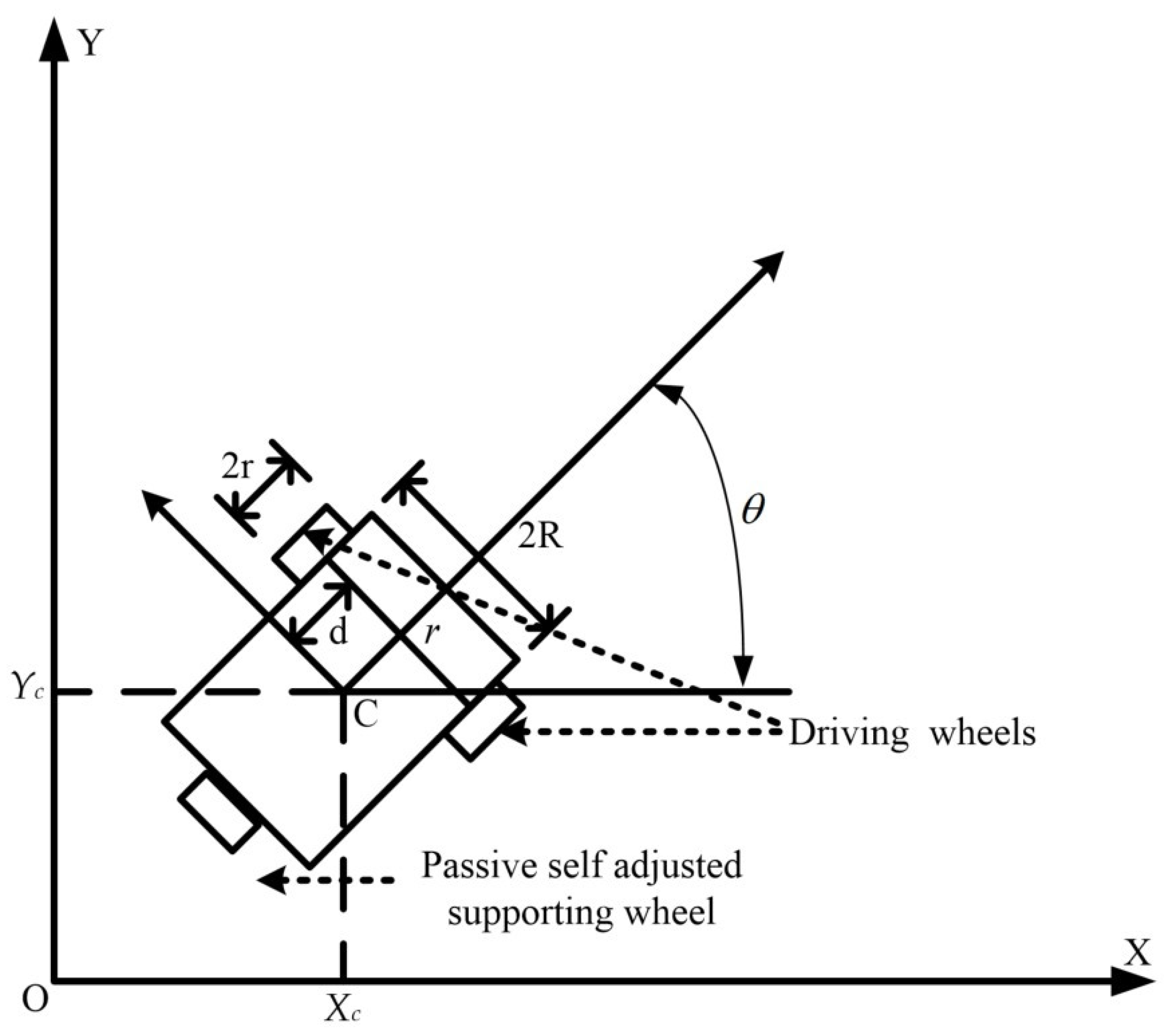
Figure 1. The wheeled mobile robot model.
Applsci 10 01055 g001
Figure 2. Circular trajectory tracking result of H2 proposed control design with respect to four different initial conditions: (xc = 1.9 m, yc = 0 m, blue line), (xc = −1.9 m, yc= 0 m, red line), (xc = 0 m, yc = 1.9 m, green line), and (xc = 0 m, yc = −1.9 m, purple line).
Applsci 10 01055 g002
Figure 3. Results of circular trajectory tracking errors concerning initial point (xc = 1.9 m, yc = 0 m).
Applsci 10 01055 g003
Figure 4. Results of circular trajectory tracking errors concerning initial point (xc = −1.9 m, yc = 0 m).
Applsci 10 01055 g004
Figure 5. Results of circular trajectory tracking errors concerning initial point (xc = 0 m, yc = 1.9 m).
Applsci 10 01055 g005
Figure 6. Results of circular trajectory tracking errors concerning initial point (xc = 0 m, yc = −1.9 m).
Applsci 10 01055 g006
Figure 7. Results of circular trajectory tracking torques concerning initial point (xc = 1.9 m, yc = 0 m).
Applsci 10 01055 g007
Figure 8. Results of circular trajectory tracking torques concerning initial point (xc = −1.9 m, yc = 0 m).
Applsci 10 01055 g008
Figure 9. Results of circular trajectory tracking torques concerning initial point (xc = 0 m, yc = 1.9 m).
Applsci 10 01055 g009
Figure 10. Results of circular trajectory tracking torques concerning initial point (xc = 0 m, yc = −1.9 m).
Applsci 10 01055 g010
Figure 11. S type trajectory tracking result of H2-proposed control design with respect to four different initial conditions: (xc = 1.9 m, yc = 0 m, blue line), (xc = −1.9 m, yc = 0 m, red line), (xc = 0 m, yc = 1.9 m, green line), and (xc = 0 m, yc = −1.9 m, purple line).
Applsci 10 01055 g011
Figure 12. Results of S-type trajectory tracking errors concerning initial point (xc = 1.9 m, yc = 0 m).
Applsci 10 01055 g012
Figure 13. Results of S-type trajectory tracking errors concerning initial point (xc = −1.9 m, yc = 0 m).
Applsci 10 01055 g013
Figure 14. Results of S-type trajectory tracking errors concerning initial point (xc = 0 m, yc = 1.9 m).
Applsci 10 01055 g014
Figure 15. Results of S-type trajectory tracking errors concerning initial point (xc = 0 m, yc = −1.9 m).
Applsci 10 01055 g015
Figure 16. Results of S-type trajectory tracking torques concerning initial point (xc = 1.9 m, yc = 0 m).
Applsci 10 01055 g016
Figure 17. Results of S-type trajectory tracking torques concerning initial point (xc = −1.9 m, yc = 0 m).
Applsci 10 01055 g017
Figure 18. Results of S-type trajectory tracking torques concerning initial point (xc = 0 m, yc = 1.9 m).
Applsci 10 01055 g018
Figure 19. Results of S-type trajectory tracking torques concerning initial point (xc = 0 m, yc = −1.9 m).
Applsci 10 01055 g019