Abstract
The characteristics of black carbon and nitrogen oxide reduction versus the water content of emulsion fuel were studied by numerical methods, and a method of reducing fuel consumption was achieved by adjusting the turbocharger compression ratio. The results of the combustion period characteristics, versus the three types of emulsion fuel and the turbocharger compression ratios, shows that the combustion period is shortened in the order of CR00 > CR01 > CR02 > CR03, according to the compression ratio of the turbocharger. As the fuel water content increases, the combustion period is shortened in the order of EMDO16 < EMDO13 < EMDO10. The nitrogen oxide and black carbon reduction was because the combustion period increased, with increasing compression ratio, while the combustion period was shortened, with increasing moisture content of emulsion fuel. This also caused is an increase in the combustion pressure and a shortening of the combustion period, due to the expansion of the volume, in turn due to the micro-explosion of water. This may be due to the shortening of the post combustion period and the reduction of black carbon emissions. In addition, combustion was accelerated in the order—CR00 > CR01> CR02> CR03. By optimizing the water content of the emulsion fuel and turbocharger compression ratio, while considering the exhaust emission and combustion state, reduction of the fuel consumption rate and output improvement are shown.
1. Introduction
Economic development and industrialization have increased the use of fossil fuels worldwide, and fossil fuels are now central to modern society. Fossil fuels provide comfort in use, but the global warming caused by greenhouse gases, ozone layer destruction, and acid rain caused by sulfur oxides (SOx) and nitrogen oxides (NOx), are largely affected by emissions from the combustion of fossil fuels. This is occurring on a global scale [1,2,3,4]. Due to increasing environmental pollution, emission regulations are being strengthened around the world, and the International Maritime Organization (IMO) is trying to tighten the regulation of air pollutants emitted from ships, which are becoming more significant. The Regulations for the Prevention of Air Pollution from MARPOL (The International Convention for Prevention of Marine Pollution for Ships) Annex [5,6], which regulate the quality of sulfur oxides (SOX), volatile organic compounds (VOCs), off-gas incinerator emissions, and fuel oils, have been revised and adopted [7]. The main purpose of IMO emission regulations is to reduce NOx emissions levels, and Table 1 shows these NOx emission reduction levels in stages. In the case of ships, the emission standard is legally less stringent than that for automobiles, and, since marine fuels are high viscosity fuel oils, the concentration of pollutants is high, and the possibility of incomplete combustion is high [8,9].

Table 1.
International Maritime Organization (IMO) Tier III regulation [5].
The low fuel consumption and high explosive power of diesel engines have been used in many applications, such as onshore and marine engines. However, air pollution caused by diesel engines is another challenge to humans, and research is being conducted in various ways, such as pre-treatment technology and post-treatment technology, to reduce such pollution. Specifically, as IMO regulations on ship diesel engines are tightened, corresponding pollution reduction technology is being developed. Emulsion fuel use, one of the technologies that attracts attention, characterizes the exhaust gas emitted from diesel engines. Because pollution reduction technology has an excellent effect on the reduction of NOx and PM (particle matter) [10,11,12,13], that technology is put to practical use. Additionally, much fuel consumption reduction is expected for study continuation. Efforts have also been made to apply these technologies, which have a number of positive use effects, to heavy oil C, which constitutes a large portion of the fuel in ships [14], and is easier to emulsify than other fuels. However, emulsified fuel is difficult to heat to a high temperature and has a high viscosity, which makes it difficult for actual ship use. Emulsion fuels are also difficult to combust because of their unusual combustion characteristics compared to other fuels.
There are two main ways to improve the exhaust gas. Before the fuel is used it can be treated to remove sulfur and metals that emit harmful gases, and to improve combustion. Ancillary technologies include delayed fuel injection, reshaped combustion chambers, improved fuel injection systems, and recirculated exhaust and water. Pre-treatment methods include the use of emulsified fuels, using diesel oil-water emulsification. Secondly, post-treatment methods include catalytic decomposition, catalytic reduction, absorption, and adsorption, to remove NOx contained in the exhaust gas. In the process of reducing NOx, by using after-treatment devices such as SCR (selective catalytic reduction), which is the most widely used post-treatment method in the case of ship oil, highly sulfurous compounds cause soot, sulphate, and nitrogen oxides to be emitted in the exhaust gas. Due to the large amount of material discharged, the durability of SCR is significantly reduced, requiring pre-treatment of the fuel [15,16,17,18].
However, alternative fuel technology is being actively researched to lessen disadvantages such as power degradation, corrosiveness, and fuel viscosity, for application to existing engines. Among alternative fuel technologies, emulsion fuels are readily producible from conventional fuels, such as diesel, and are a blend of water and emulsifiers added by proportions. Additionally, due to the absorption of the latent heat of evaporation, in turn due to the evaporation of water during the combustion process of a water-containing fuel, it is possible to atomize the fuel due to the lower combustion temperature in the combustion chamber, and the micro-explosion due to rapid evaporation. Thereby, NOx, SO2, and soot emissions can be reduced simultaneously. In addition, unlike the existing engine technology, new engine combustion technology, and post-treatment technology, no additional device is required, and research has attracted attention because it can be used for an existing engine without any modifications [15,16,17,18,19].
Among alternative fuel technologies, emulsion fuel refers to a state in which a liquid is mixed with a different liquid, by adding a surfactant to the two liquids, not otherwise well mixing. When producing emulsion fuel using fuel and water, there is an oil-in-water type (O/W) which is water in fuel, and a water-in-oil type (W/O) which is fuel in water. In W/O diesel-water emulsion fuel, micro-explosions occur when water particles evaporate first, due to the difference in the boiling points of water and diesel fuel, when injected into the cylinder. Under normal atmospheric conditions, the boiling point of water is 100 °C, and the diesel fuel boiling point is 160–400 °C, depending on the components involved. If the pressure in the cylinder is assumed to be 30 bar when the fuel is injected, the boiling point of the water is about 135 °C and the water will evaporate before the diesel fuel, under any ambient conditions. When water explodes, the fuels surrounding the water particles are finely divided and then promote fuel atomization [14,18,19]. Thus, if atomization is accelerated, soot can be reduced due to combustion improvement. After the water is vaporized, the high evaporative latent heat of water absorbs the heat energy in the combustion chamber, and lowers the combustion temperature, thereby reducing NOx levels. [15,16] The focus here is on applicability to diesel engines, without the need for additional equipment. However, under low load conditions more exhaust emissions, mainly from incomplete combustion, such as THC (Total Hydro-carbon) and CO (Carbon Oxide) are generated than by existing diesel fuels, and, as high load conditions rise, emissions are similar to conventional diesel fuels [17,18,19]. It can be reasoned that the evaporation of water particles in the fuel is delayed, due to the relatively low ambient temperatures and the pressure under low load conditions. Thus, the possibility arises that the atomization and evaporation characteristics of diesel fuel will be inferior when compared to the spraying characteristics of emulsion fuels alone [14]. As a study on emulsion fuels, Ithnin et al. [15] produced emulsion fuels containing water and low diesel, and compared the exhaust gas emissions. Ithnin [15] reported a 41% reduction in PM emissions and a 35% reduction in PM. Lim et al. [16] reported a 30% reduction in NOx and a 59% reduction at full load, when compared to diesel, at a water mixing ratio of 25%. In addition, Kim [19,20] confirmed that NOx and 35% smoke decreased when the water content of emulsion fuel was 15% in the full load region. As in the case of using water, it is possible to expect NOx reduction at the same time, due to the reduction of soot from the micro-explosion phenomenon, caused by the intense evaporation of water, and the effect of promoting combustion through free radicals, and the decrease of the combustion chamber temperature due to the latent heat of evaporation of water [21]. As shown in Figure 1 [22], in the micro-explosion phenomenon, the difference in the boiling point between diesel and water upon fuel injection in a combustion chamber results in the evaporation of water droplets and a more thorough splitting of fuel droplets. As a result, secondary atomization contributes to enhancing the air–fuel mixture and reducing the incomplete combustion.
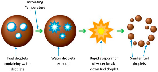
Figure 1.
Mechanism of micro-explosion phenomenon [22].
Here, the characteristics of nitrogen oxide and black carbon reduction, versus the water content of the emulsion fuel, were studied using the numerical analysis method, and specifically, exhaust gas and fuel consumption rates as a result of adjusting the moisture content.
2. Materials and Research Methods
2.1. Experiment Method
In this study, a schematic of the system that reduces emissions of nitrogen oxides and black carbon in actual marine engines using emulsion fuel is shown in Figure 2.
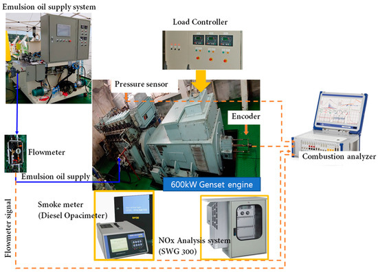
Figure 2.
Schematic diagram for four-stroke marine engine.
Figure 2 shows a schematic diagram for studying the combustion and exhaust characteristics of three types of emulsion fuel and MDO in an actual ship according to the water content. The four-stroke turbocharger engine used in this study is a 600-kW generator engine. As shown in Figure 2, the four-stroke engine consisted of a generator engine, a controller panel, a data acquisition system, an exhaust gas analyzer, and a pressure sensor. The engine load was adjusted using a load cell in the ship. The pressure sensor was installed on the No. 6 cylinder through a hole in the cylinder head, and signals from the data acquisition device, the flow meter and the encoder were simultaneously acquired from the sensor (model 6056 A, Kistler, Winterthur, Switzerland). The resolution of the encoder used in this study is 1 CA. The heat generation rate was calculated by applying a zero-dimensional combustion model and averaging combustion data of 100 cycles.
As shown in Table 2, a 600-kW generator engine was used to study the characteristics of nitrogen oxide and black carbon reductions, versus the water content of an emulsion fuel. Table 3 shows the experimental conditions of the combustion pressure and heat release in accordance with three types of emulsion oil.
Table 2.
Specifications for test engine.
Table 3.
Experimental condition.
The emulsion fuel, which was produced from the emulsion fuel supply system shown in Figure 1, was sampled before each test was performed. Next, the compositions of the four fuels, containing marine diesel oil and 10%, 13%, and 16% of water, and additives for certified fuels, were analyzed and the results are shown in Table 4.
Table 4.
Emulsified oil fuel properties used in the marine engine.
2.2. Numerical Analysis Method
Using the results obtained through the experiments, the combustion and exhaust characteristics according to the change of compression ratio were predicted by numerical method. It is to secure the reliability of the experiment by deriving important factors necessary for applying it in the future experiment. Numerical and experimental results of the emulsion fuel were primarily compared and analyzed. Based on the numerical analysis, previous studies on combustion and exhaust characteristics according to the pressure ratio of the turbocharger were carried out. The software adopted for the simulation was the AVL BOOST©, version 2019.1, which provides a graphical user interface (GUI) including icons that represent the components of an internal combustion engine (ICE). Once selected and interconnected, the icons allow one to open a window through which the geometrical and operational data of the engine, as well as the mathematical models that make up the simulation, are inserted. The 1D computational fluid dynamics (CFD) model is shown in Figure 3 which of engine model is same to Table 2. Once all necessary data has been collected, the model is built in the AVL BOOST© software [23]. This tool uses the conservation equations of mass, energy, and momentum for modelling intake and exhaust collector ducts. However, those equations are connected with contour conditions obtained from the modelling of other engine components, like cylinders, turbochargers, valves or heat exchangers. Each component is especially modelled to consider the conservation equations, and also its own special behavior. In Figure 3, SB1 and SB2 are the inlet and outlet boundary; TC1 is the turbine and compressor (charger); C1 through C6 represent the six cylinders of the engine; CO1 represent the heat exchanger; PL1 is the manifold; and MP1 through MP28 are measurement points. The model’s main elements are also identified in Figure 3—the air cooler, air filters, compressors, manifolds, cylinders and turbines, all connected by ducts. The engine configuration as modelled considers the main engine characteristics, i.e., the firing order C1-C2-C4-C6-C5-C3 and the firing angle of each cylinder, with respect to reference Cylinder 1 (C1), the spatial distribution of cylinders, etc. C1 in the model (AVL BOOST©) is connected with the element—Engine 1 (E1), and that defines the type of engine used, its operating speeds, moments of inertia, and break mean effective pressure (BMEP is calculated from measured dynamometer torque). The combustion method is chosen for the experimental mixing-controlled combustion (MCC) AVL combustion, that predicts the rate of heat released (ROHR means the amount of heat generated in unit time per unit volume of the combustion chamber) and the NOx emissions, based on the quantity of fuel in the cylinder and the turbulent kinetic energy introduced by the injection of fuel.
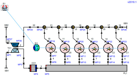
Figure 3.
AVL BOOST© model for a four-stroke marine diesel engine.
The first law of thermodynamics, applied to the combustion cylinder, dictates that the change of the internal energy in the cylinder equals the sum of the piston works, fuel heat input, wall heat losses, and the enthalpy flow due to blow-by. This is applied to AVL BOOST© to calculate the thermodynamic state of a cylinder:
where mc is the mass in the cylinder; u is the specific internal energy; Pc is the cylinder pressure; V is the cylinder volume; QF is the fuel energy; QW is the wall heat loss; α is the crank angle; hBB is the enthalpy of blow-by; and, mBB is the blow-by mass flow [22].
The heat transfer to the walls of the combustion chamber, including cylinder head, piston, and cylinder liner, can be calculated as follows [22]:
where Qwi is the wall heat flow; Ai is the surface area; and, Tc and Twi are the gas temperatures in the cylinder and wall, respectively.
The combustion in direct injection compression ignition engines can be considered by two processes—premixed combustion (PMC) and MCC. The combustion model in this study used MCC [22], where:
where Qtotal is the total heat release over the combustion process [KJ]; and, QPMC and QMCC are heat inputs for the premixed combustion and cumulative heat release by the MCC [KJ], respectively.
The NOx formation model is based on the well-known Zeldovich mechanism, and black carbon formation is described by two steps—formation and oxidation. The net of rate of changes in soot mass msoot is the difference between the rates of soot formed msoot and oxidized msoot.ox [22].
3. Results
3.1. Characteristics of Combustion Pressure and Rate of Heat Release versus the Compression Ratio of the Turbocharger Nozzle Ring
Figure 4 shows the combustion pressure and heat generation rate versus the change in the turbocharger nozzle ring, using emulsified MDO containing 10% moisture. Here, Test_P is the combustion chamber pressure diagram obtained through the experiment. Base_P is the numerical result obtained by comparing with experimental results. CR00_P, CR01_P, CR02_P and CR03_P are combustion chamber pressure diagrams obtained through numerical analysis according to the compression ratio of the turbocharger. R in Test_R means Rate of heat release. From Figure 4 it is seen that the combustion pressure increased with increasing pressure ratios of the nozzle ring of the turbocharger. It is seen that combustion is activated due to an increase in the amount of air introduced, in turn due to an increase in the pressure ratio. In addition, when the experimental results were compared with the numerical results, the combustion pressure was seen to increase as the pressure ratio of the turbocharger increased, and the overall combustion pressure increased due to the effects of the pressure ratio of the turbocharger and the use 10% emulsified fuel. In addition, from the results in all load ranges of Figure 4a–e, comparing the characteristics of heat generation rate with the experimental results shows that post combustion is shortened, due to the pressure ratio of the turbocharger and the use of emulsion fuel. This is expected to affect the reduction of nitrogen oxides and black carbon.
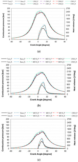
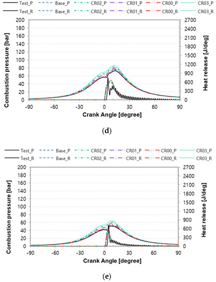
Figure 4.
Combustion pressure and heat release characteristics versus the compression ratio of the turbocharger at Emulsified MDO 10%. (a) 100% of engine loads (b) 75% of engine loads. (c) 50% of engine loads. (d) 25% of engine loads. (e) 10% of engine loads.
Figure 5 and Figure 6 show the combustion pressure and heat generation rate, versus the compression ratio of the turbocharger, when the water content of the emulsion fuel is 13% and 16%, respectively. As shown in Figure 5 and Figure 6, combustion pressure increases and post-combustion is shortened by the effect of water on the emulsion fuel.
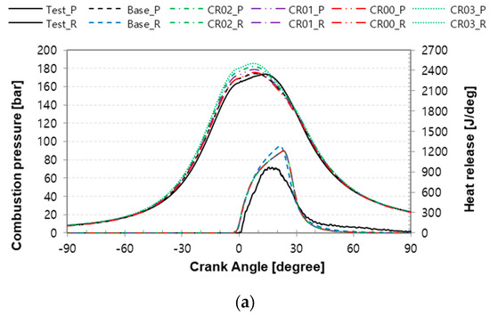
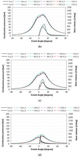
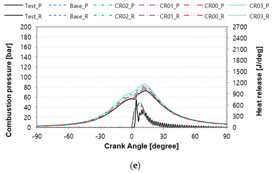
Figure 5.
Combustion pressure and heat release characteristics versus the compression ratio of the turbocharger at Emulsified MDO 13%. (a) 100% of engine loads. (b) 75% of engine loads. (c) 50% of engine loads. (d) 25% of engine loads. (e) 10% of engine loads.
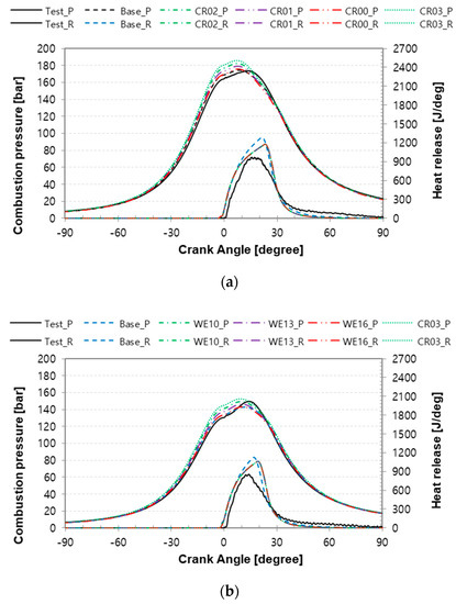
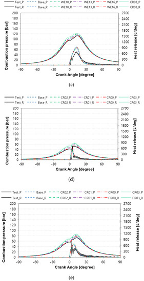
Figure 6.
Combustion pressure and heat release characteristics versus the compression ratio of the turbocharger at Emulsified MDO 16%. (a) 100% of engine loads. (b) 75% of engine loads. (c) 50% of engine loads. (d) 25% of engine loads. (e) 10% of engine loads.
Figure 7 shows the results of the location of the maximum pressure of combustion, versus the turbocharger compression ratio and the water content of the emulsion fuel. The experimental results and numerical results show that the location of the maximum pressure of combustion tends to be very consistent. Figure 7 shows that the location of the maximum pressure of combustion is retarded in the lower region of the model of the basic engine, but the position of the maximum pressure of combustion is significantly advanced in the region of more than 50% of load. This shows that the duration of post-combustion can be shortened, which is expected to reduce black carbon in the exhaust emissions. Figure 8 shows that the turbocharger compression ratio is CR03 and the moisture content is 16%, depending on the water content of the emulsion fuel. Due to this phenomenon, fuel atomization was accelerated due to micro-explosion of water, and combustion time was shortened due to sufficient air, in turn due to the increased compression ratio of the turbocharger.
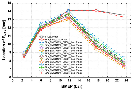
Figure 7.
Characteristics of the location of the peak combustion pressure versus the compression ratio of the turbocharger and three types of emulsified MDOs.
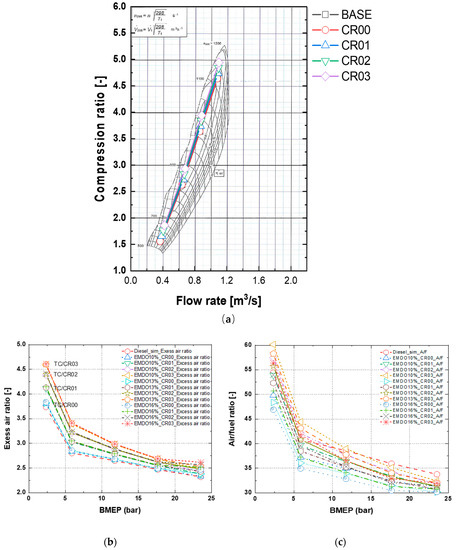
Figure 8.
Characteristics of the compression ratio, Air/Fuel ratio and access air ratio of the turbocharger versus the break mean effective pressure (BMEP). (a) Turbocharger map, (b) access air ratio, (c) Air/Fuel ratio.
3.2. Characteristics of Combustion and ROHR versus the Compression Ratio of the Turbocharger
Figure 8 shows the compression ratio and access air ratio of the turbocharger versus the load. Here, the effects of combustion and exhaust characteristics on the compression ratio were investigated, in order to show the optimum combustion and exhaust characteristics, versus the performance of the turbocharger and the emulsion fuel. As the pressure ratio of the turbocharger shown in Figure 8a increases, the excess air ratio and the air-fuel ratio increase. The air–fuel ratio and excess air ratio increased in the order of EMDO10% <EMDO13% <EMDO16% according to the water content of emulsion fuel.
Figure 9 shows the effects of the combustion pressure and heat generation rate, versus the condition of the emulsion fuel, versus the change in turbocharger compression ratios. Figure 9a shows the combustion pressure and heat generation rate at an engine load of 100%. The combustion pressure increased slightly as the water content in the fuel increased, but the heat generation rate curve showed that the combustion was rapidly burned, and the post-combustion period was shortened. This may be due to the increase in combustion pressure due to volume expansion, in turn due to the evaporation of water. As the turbocharger compression ratio is increased (CR00 < CR01 < CR02 < CR03), the heat generation rate curve shows the characteristics of faster combustion and a shorter combustion period. Therefore, it is thought that black carbon is reduced due to the shortening of the combustion period, that is, the shortening of the post combustion period due to the promotion of atomization of fuel. Figure 9b–d shows the combustion pressure and heat generation characteristics of the turbocharger, under the conditions of CR01, CR02, and CR03, when the engine load is 100%. As mentioned above, the combustion pressure increases with increasing compression ratio of the turbocharger, and the post combustion period is shortened. However, when the compression ratio is CR03, the combustion pressure increases by more than 10 bar. It is considered that the optimization of the combustion and exhaust characteristics, versus the compression ratio of the turbocharger and the water content of the emulsion fuel, can be expected to reduce fuel consumption, as well as NOx and black carbon.
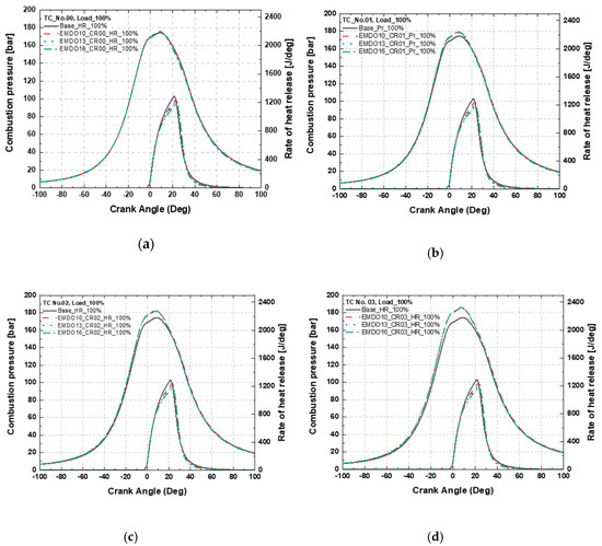
Figure 9.
Characteristics of the combustion pressure and the heat release versus the turbocharger nozzle ring compression ratio. (a) TC No. 00. (b) TC No. 01. (c) TC No. 02. (d) TC No. 03.
3.3. Characteristics of the Combustion Duration versus the Compression Ratio of the Turbocharger and the Water Concentration of the Emulsified Marine Diesel Oil
Figure 10 shows the effects on the combustion duration by the three types of emulsion fuel and the turbocharger compression ratios. The combustion duration is so characterized because the combustion duration is shortened in the order: CR00 > CR01 > CR0 2 > CR03, as the compression ratio (CR) of the turbocharger is increased. That is because the combustion period increases with increasing compression ratios, while the combustion duration is shortened with increasing water contents of the emulsion fuel. This causes the combustion temperature to be lowered, due to latent evaporation, in turn due to a phase change in the high temperature and high-pressure combustion conditions of the water contained in the fuel, and due to an increase, the combustion pressure and a shortening of the combustion duration, in turn due to the expansion of the volume, in turn due to the micro-explosion of water.
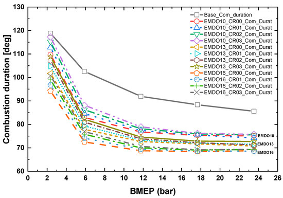
Figure 10.
Characteristics of the combustion duration versus three types of emulsified MDOs and four types of turbocharger nozzle rings.
Figure 11 shows the results of mass burn friction greater than 90% versus the three emulsion fuels and the turbocharger compression ratio. Regardless of the load condition, the fuel is rapidly burned in the order—EMDO16 < EMDO13 < EMDO10, due to the characteristics of the emulsion fuel. This may be due to the shortening of the post combustion period and the reduction of black carbon emissions. In addition, combustion was accelerated in the order of CR00 > CR01 > CR02 > CR03. The water content of the emulsion fuel and the compression ratio of the turbocharger show trade-off characteristics. By optimizing the water content of the emulsion fuel and the compression ratio of the turbocharger, it is possible to optimize the emission reduction and the fuel reduction.
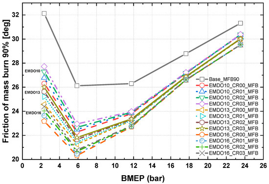
Figure 11.
Characteristics of the friction at 90% mass burning versus three types of emulsified MDOs and four types of turbocharger nozzle rings.
Figure 12 shows the characteristics of the mass burning friction of 90% and the combustion duration, versus the moisture content of the emulsion fuel, when the compression ratio is CR03. Therefore, the combustion duration and the mass burning friction of 90% are shortened, as the water content in the emulsion fuel increases. As shown in the combustion pressure and heat generation rate curves above, the combustion period is shortened. By shortening the combustion period, black carbon exhaust emissions will be reduced due to the shortening of the post combustion duration.
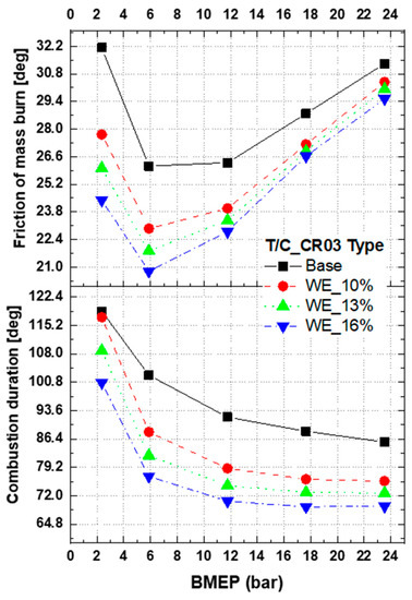
Figure 12.
Characteristics of the friction at 90% mass burning and the combustion duration versus three types of emulsified MDOs versus the CR03 type turbocharger compression ratio (meaning of WE_10% is water emulsion including 10% water concentration).
3.4. Characteristics of the Combustion Duration versus the Compression Ratio of the Turbocharger and the Water Concentration of the Emulsified Marine Diesel Oil
Figure 13 shows the fuel consumption versus load change, versus the turbocharger compression ratio and the water content of the emulsified fuel. Therefore, the overall brake specific fuel consumption increases as the water content in the fuel increases. In the case of fuel containing water, the consumption of emulsified fuel containing water increased as the amount of water increased, and the amount of rated fuel required for the load increased.
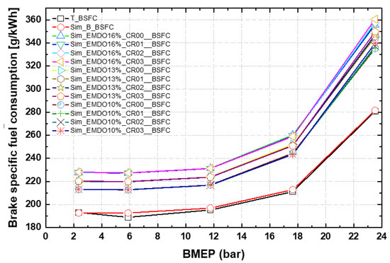
Figure 13.
Characteristics of the brake specific fuel consumption versus the turbocharger compression ratio and emulsified marine diesel oil.
Figure 14 shows the fuel consumption versus the turbocharger compression ratio and the three emulsified fuels, without (Figure 14a) and with water (Figure 14b). In the case of emulsified fuel containing water, the fuel consumption tended to increase as much as the water was contained. However, as a result of comparing the consumption of pure fuel, excluding moisture contained in emulsified fuel, the fuel consumption rate decreased in the order—EMDO10 < EMDO13 < EMDO16. It was found that the fuel consumption rate was more affected by the moisture content of the emulsion fuel than by the turbocharger compression ratio.
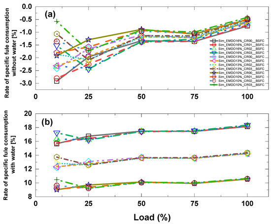
Figure 14.
Characteristics of the variation rate of Specific Fuel Consumption (SFC) versus the conditions—without water (a) and with water (b).
3.5. NOx and Black Carbon Reduction Rates versus the Compression Ratio of the Turbocharger and the Water Concentration of the Emulsified Marine Diesel Oil
Figure 15 graphs the nitrogen oxide and black carbon emissions versus the turbocharger compression ratio and three types of emulsified marine diesel oil. In the lower BMEP condition (2.1 bar) the emission characteristics were slightly higher than those of the basic engine model, but lower exhaust emissions were obtained at other loads.
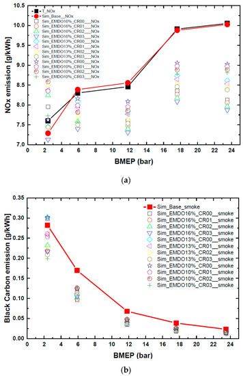
Figure 15.
Emission characteristics of nitrogen oxide (NOx) and black carbon versus the turbocharger compression ratio and three types of emulsified marine diesel oil; (a) NOx emission, (b) black carbon emission.
Figure 16 shows the characteristics of the basic engine’s NOx and black carbon reductions versus the turbocharger compression ratio and the emulsion fuel. Figure 16a shows the characteristics of nitrogen oxide reduction with the basic engine. As the compression ratio of the turbocharger increases, the nitrogen oxide reduction characteristics are excellent and the water content in the emulsion fuel increases. As a result, the effect of reducing the nitrogen oxides shows outstanding characteristics. This is because nitrogen oxides are reduced by lowering the temperature in the combustion chamber, due to the increase in latent heat of evaporation as the water content of the fuel increases. Figure 16b shows the characteristics of black carbon reduction versus the turbocharger compression ratio and the emulsion fuel. Contrary to the results of Figure 16a, the reduction of the black carbon decreases as the compression ratio of the turbocharger increases, but the reduction of the black carbon is clearly shown as the water content of the emulsion fuel increases. These results indicate that the effect of moisture in the emulsion fuel is a very important factor in the reduction of nitrogen oxides and black carbon. By optimizing the water content of the emulsion fuel and the compression ratio of the turbocharger, versus the exhaust emissions and the combustion state, it is considered that not only the fuel consumption rate is reduced but also the output improvement is very important.
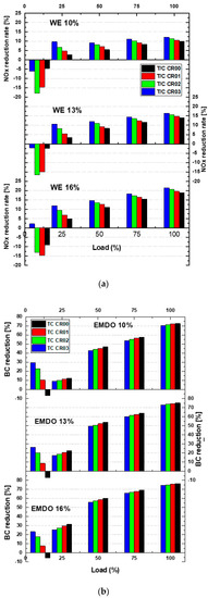
Figure 16.
Reduction rate of NOx and black carbon versus turbocharger compression ratio and three types of emulsified marine diesel oil; (a) NOx emission, (b) black carbon emission.
4. Discussion
Here, the characteristics of nitrogen oxide and black carbon reduction, according to the water content of the emulsion fuel, were studied by the numerical method, and reducing fuel consumption was achieved by adjusting the turbocharger compression ratio. The study was conducted varying the exhaust gas and the fuel consumption rate by adjusting the moisture content. The results are as follows:
- (1).
- Using the comprehensive results of the maximum pressure position of combustion versus the turbocharger compression ratio and the moisture content of the emulsion fuel, in the lower load region, the position of the maximum pressure of combustion was retarded in the model of the basic engine. In the region of more than 50% load, the position of the maximum pressure of combustion is advanced.
- (2).
- Characteristics of the turbocharger compression ratio and the emulsion fuel versus the position of maximum combustion pressure were studied. As a result, the turbocharger compression ratio is CR03 and the moisture content is 16%, according to the moisture content of the emulsion fuel. Due to this phenomenon, fuel atomization was accelerated, due to micro-explosion of water, and combustion time was shortened, due to sufficient air, in turn due to the increased compression ratio of the turbocharger.
- (3).
- As a result of comparing the turbocharger compression ratio and the fuel consumption, in the cases of including water and excluding water, for the three types of emulsified fuels, the fuel consumption of the emulsified fuel containing water tended to increase. However, as a result of comparing the consumption of pure fuel, excluding moisture contained in emulsified fuel, the fuel consumption rate decreased in the order of EMDO10 < EMDO13 < EMDO16.
- (4).
- The results of the combustion period characteristics, versus the three types of emulsion fuel and the turbocharger compression ratios, shows that the combustion period is shortened in the order of CR00 > CR01 > CR02 > CR03, according to the compression ratio of the turbocharger. As the fuel water content increases, the combustion period is shortened in the order of EMDO16 < EMDO13 < EMDO10.
- (5).
- The nitrogen oxide and black carbon reduction was because the combustion period increased, with increasing compression ratio, while the combustion period was shortened, with increasing moisture content of emulsion fuel. This causes the combustion temperature to be lowered due to latent evaporation, in turn due to a phase change under high temperature and high-pressure combustion conditions of water contained in the fuel. Additionally, it caused an increase in the combustion pressure and a shortening of the combustion period, due to the expansion of the volume, in turn due to the micro-explosion of water. This may be due to the shortening of the post combustion period and the reduction of black carbon emissions. In addition, combustion was accelerated in the order—CR00 > CR01> CR02> CR03.
- (6).
- As a result of reducing exhaust emissions, black carbon reduction was lowered as the compression ratio of the turbocharger was increased, but black carbon reduction was clearly shown as the water content of the emulsion fuel increased. By optimizing the water content of the emulsion fuel and the compression ratio of the turbocharger, versus the exhaust emissions and the combustion state, it is shown that not only is the fuel consumption rate reduced but also the output improvement is very significant.
Author Contributions
Conceptualization, I.C.; methodology, I.C.; investigation, C.L.; data curation, I.C.; writing—original draft preparation, C.L.; writing—review and editing, C.L. All authors have read and agreed to the published version of the manuscript.
Funding
The APC was funded by the Pukyong National University Research Fund in 2019 (CD20191039)
Conflicts of Interest
The authors declare no conflict of interest.
References
- Kwon, K.-S.; Choi, K.-J. Development of technology about fuel change and miniature of fuel sludge for medium and low engine. In Proceedings of the MarineCom Technology Seminar, Boston, MA, USA, 6 October 2007. [Google Scholar]
- Hsu, A.; Esty, D.C.; Levy, M.A.; de Sherbinin, A. 2016 Environmental Performance Index (EPI); Yale Center for Environmental Law and Policy (YCELP) and Center for International Earth Science Information Network (CIESIN), Columbia University: New York, NY, USA, 2016. [Google Scholar] [CrossRef]
- Subramanian, K. A comparison of water–diesel emulsion and timed injection of water into the intake manifold of a diesel engine for simultaneous control of NO and smoke emissions. Energy Convers. Manag. 2011, 52, 849–857. [Google Scholar] [CrossRef]
- Andrea, B.; Renxian, L.; Konstantinos, B. Influence of Water-Diesel Fuel Emulsions and EGR on Combustion and Exhaust Emissions of Heavy Duty DIDiesel Engines Equipped with Common-Rail Injection System; SAE Technical Paper 2003-01-3146; SAE: Warrendale, PA, USA, 2003. [Google Scholar]
- MEPC. 66/6/Consideration and Adoption of Amendments to Mandatory Instruments. In Comments to the Approval at MEPC 65 of Amendments to the Effective Date of the NOx Tier III Standards; MEPC: Marshall Islands, Norway, 2013. [Google Scholar]
- International Organization for Standards. Petroleum Products-Fuels (Class F)-Specifications of Marine Fuels; International standard, ISO 8217:2012(E); ISO: Geneva, Switzerland, 2012. [Google Scholar]
- Hironori, S.; Koji, U. Feasibility Study on the Utilization of Water-in-Oil Type Emulsified Fuels to Small DI Diesel Engines; SAE 2011-32-0602; SAE: Warrendale, PA, USA, 2011. [Google Scholar]
- Park, J.W.; Huh, K.Y.; Park, K.H. Experimental Study on the Combustion Characteristics of Emulsified Diesel in a RCEM. In Proceedings of the Seoul FISITA World Automotive Congress, Seoul, Korea, 12–15 June 2000. [Google Scholar]
- Park, J.K.; Oh, J.M.; Kim, H.I.; Lee, C.H.; Lee, K.H. Combustion Characteristics of MDO and MDO Emulsion in Automotive Diesel Engine. Trans. KSME 2012, 36, 945–951. [Google Scholar] [CrossRef]
- Kim, M.C.; Lee, C.S. It’s Effects for Engine Emission of Water/Oil Emulsified Fuel. Anal. Sci. Technol. 2008, 21, 159–166. [Google Scholar]
- Han, D.H.; Kang, J.H.; Kim, M.C.; Lee, K.B.; Roh, H.H. A Study on Emission Characteristics of MDO Emulsion Using the FT-IR Spectroscopy. In Proceedings of the KSAE Spring Conference Proceedings, Seoul, Korea, May 2013; pp. 554–559. [Google Scholar]
- Attia AM, A.; Kulchitskiy, A.R. Influence of the Structure of Water-in-Fuel Emulsion on Diesel Engine Performance. Fuel 2014, 116, 706–708. [Google Scholar] [CrossRef]
- Huo, M.; Lin, S.; Liu, H.; Lee, C.F. Study on the Spray and Combustion Characteristics of Water-Emulsified Diesel. Fuel 2014, 123, 218–229. [Google Scholar] [CrossRef]
- Ojala, J.; Sirviö, J.A.; Liimatainen, H. Nanoparticle emulsifiers based on bifunctionalized cellulose nanocrystals as marine diesel oil–water emulsion stabilizers. Chem. Eng. J. 2016, 288, 312–320. [Google Scholar] [CrossRef]
- Ithnin, A.M.; Ahmad, M.A.; Bakar MA, A.; Rajoo, S.; Yahya, W.J. Combustion Performance and Emission Analysis of Diesel Engine Fuelled with Water-in-Diesel Emulsion Fuel Made from Low-Grade Diesel Fuel. Energy Convers. Manag. 2015, 90, 375–382. [Google Scholar] [CrossRef]
- Lim, J.K.; Cho, S.G.; Hwang, S.J.; Yoo, D.H. Effect on Characteristics of Exhaust Emissions by Using Emulsified Fuel in Diesel Engine. J. Korean Soc. Mar. Eng. 2007, 31, 44–50. [Google Scholar]
- Oh, J.; Im, M.; Oh, S.; Lee, C. Comparison of NOx and Smoke Characteristics of Water-in-Oil Emulsion and Marine Diesel Oil in 400-kW Marine Generator Engine. Energies 2019, 12, 228. [Google Scholar] [CrossRef]
- Kim, D.; Lee, C. SCR Performance Evaluations in Relation to Experimental Parameters in a Marine Generator Engine. J. Mar. Sci. Eng. 2019, 7, 67. [Google Scholar] [CrossRef]
- Kim, M.; Oh, J.; Lee, C. Study on Combustion and Emission Characteristics of Marine Diesel Oil and Water-In-Oil Emulsified Marine Diesel Oil. Energies 2018, 11, 1830. [Google Scholar] [CrossRef]
- Kim, M.C. The Exhaust Gas Reduction of Diesel Engine by MDO (Marine Diesel Oil) Emulsion Fuel. J. Korean Soc. Environ. Eng. 2014, 36, 476–482. [Google Scholar] [CrossRef][Green Version]
- Chen, Z.; Wing, X.; Pei, Y.; Zhang, C.; Xiao, M.; He, J. Experimental Investigation of Performance and Emissions of Diesel Engines by Novel Emulsified Diesel Fuel. Energy Convers. Manag. 2015, 95, 334–341. [Google Scholar] [CrossRef]
- Park, S.; Woo, S.; Kim, H.; Lee, K. The characteristic of spray using diesel water emulsified fuel in a diesel engine. Appl. Energy 2016, 176, 209–220. [Google Scholar] [CrossRef]
- AVL BOOST Theory Reference. v2019 R1. Available online: https://www.avl.com/-/avl-boost-2019-r1 (accessed on 6 November 2019).


© 2020 by the authors. Licensee MDPI, Basel, Switzerland. This article is an open access article distributed under the terms and conditions of the Creative Commons Attribution (CC BY) license (http://creativecommons.org/licenses/by/4.0/).