Article

Experimental Study on the Cyclic Behavior of Integrated Panels for Cold-Formed Steel Shear Wall System

1
Department of Architectural Engineering, Ajou University, Suwon 16499, Korea
2
School of Civil Engineering, The University of Sydney, Sydney 2006, Australia
*
Author to whom correspondence should be addressed.
Appl. Sci. 2020, 10(5), 1649; https://doi.org/10.3390/app10051649
Submission received: 7 February 2020 / Revised: 24 February 2020 / Accepted: 26 February 2020 / Published: 1 March 2020
(This article belongs to the Section Civil Engineering)

Abstract

:
Studies on the constructability of cold-formed steel (CFS) members are lacking. In this context, this paper proposes an integrated panel to replace the studs and steel sheet in the steel-sheathed wall system used in light gauge steel frames. The integrated panel was developed, to not only exhibit better structural performance and constructability than the steel-sheathed wall system, but to also reflect the appropriate details for applications to on-site panel construction. Cyclic loading tests were performed to investigate the seismic performances of three integrated panel specimens and a steel-sheathed panel specimen. The integrated panel specimens exhibited greater deformation capacity, ductility and equivalent damping ratio than the steel-sheathed panel. Although the web slenderness of the integrated member was nearly 400, the nominal strength of the integrated panel was predictable on an AISI standard. However, for stud-reinforced integrated panels, the nominal strength was overestimated by 45%–60%, and a draft equation was proposed to predict the yield strength of these panels. The proposed equation accurately predicted the yield strength of the stud-reinforced integrated panel specimens. The study results can aid in the construction of light gauge steel frames that require reinforcing parts with a high web slenderness ratio.

1. Introduction

1.1. Research Background

In South Korea, structural design standards have been continuously improved since the enactment of the provisions of the seismic design law in 1988. Of late, there has been increasing interest in light gauge steel frames—which have robust seismic performance—as the seismic design law was recently extended, such that two or more single-family or multi-family developments are subject to earthquake-resistant design rules. This has particularly been the case since the 2016 Gyeong-ju and 2017 Po-hang earthquakes. Light gauge steel frames are built with cold-formed steel (CFS) members. These members are lightweight, and thus bring about good seismic properties [1,2,3]. As light gauge steel frames are constructed for low-rise buildings with varied demand, on-site panel construction methods are more predominantly employed than factory panel construction methods. However, on-site panel construction has a drawback, in that material transportation and deformation are likely to occur at the time of construction, thereby decreasing the initial rigidity of CFS members [4].
In light gauge steel frames, steel strap-braced and steel-sheathed wall systems are generally used to ensure seismic performance. The members of light gauge steel frames have screwed joints that are replaced with bolted joints in the steel structure. Many screw joints adversely affect workability, so an integrated member has been developed with details that minimize the use of screw joints. The integrated panel proposed in this research replaces the studs and steel sheet of a steel-sheathed wall system, as shown in Figure 1. The integrated panels developed for this purpose are presented in the paper, and are studied to compare the effects of stud reinforcement and the steel-sheathed panel on a designed testing rig. Of particular importance is identifying the behavior of the integrated panel, and predicting the nominal strength. Unlike steel-sheathed panels in which the steel sheet and studs are screwed together, an integrated panel—in which a single member resists lateral forces—is expected to be more stable to lateral forces.

1.2. Literature Review

The effective width method, introduced by von Karman [5], and subsequently modified by Winter [6], has been the primary design approach for cold-formed steel members in the AISI Specifications, including the latest edition of the North American Specification for the Design of Cold-Formed Steel Structural Members (AISI S100-16) [7]. In the effective width method, the effective width is defined through iterative calculations considering the post-buckling capacity of the member section. This method has some dimensional limitations. The limitations originate from the work of Winter [8], after which the limits of the stiffened elements in bending were updated in 1980, based upon studies conducted at the University of Missouri-Lola in the 1970s [9,10,11,12,13,14,15]. To some extent, these dimensional limitations are arbitrary; however, the limitations of AISI S100-16 hinder the applicability of the design methods.
Studies [16,17,18,19] that tested and evaluated cold-formed steel-sheathed shear walls have shown that these walls have lengths ranging from 610 to 1830 mm, and heights from 2440 mm. In this case, even if the thickness of the steel sheet is 1.6 mm, the aspect ratio of the web becomes 380 or more, when an integral member is included. This value exceeds the member’s dimension limit (web slim (height-to-thickness) ratio < 200).
Studies have been conducted to improve the seismic performance of CFS shear walls. Hong et al. [20] investigated a different type of steel shear wall, containing double-skin steel panels. The test results showed moderate ductility and energy dissipation, attributed to the post-buckling strength of the wall. However, it is difficult to machine openings for electrical points in the panels, thus limiting its practical use. Tian et al. [21] proposed steel-sheathed CFS trussed shear walls, which exhibited a significantly higher ultimate strength than conventional shear walls. However, the numbers of members and joints constituting the steel-sheathed CFS trussed shear wall were too high for on-site panel construction. Wang et al. [22] investigated the seismic behavior and parametric influence of cold-formed, thin-walled, steel tube truss shear walls. The experimental data showed that the shear walls exhibited good hysteretic behavior, ductility and energy dissipation. However, the construction of a very large number of galvanized V-shaped connectors on-site requires extended construction periods, which is a disadvantage. Although many studies have focused on improving the seismic performance of CFS shear walls, few have analyzed its constructability.

1.3. Nominal Strength of an Integrated Panel Under Combined Bending and Shear According to AISI S100-16

The design specification for cold-formed steel sections currently used in Korea was established in 1998, referring to the Specification for the Design of Cold-Formed Steel Structural Members [23]. As the Korean design specifications were enacted several years ago, and are outdated to some extent, cold-formed steel sections are designed primarily according to the AISI standard.
When a lateral force acts on a light gauge steel frame, the CFS shear wall may deform like a cantilever beam, as shown in Figure 2.
The shear force and bending moment act simultaneously on the CFS shear wall. According to AISI S100 [7], the required flexural strength M ¯ and required shear strength V ¯ for the integrated member should satisfy the following interaction equation.
( M ¯ M a l o ) 2 + ( V ¯ V a ) 2 1.0
where M a l o is the available flexural strength, and V a is the available shear strength when shear alone is considered. The required flexural strength M ¯ is equal to V ¯ h 1 . Therefore, the nominal strength of the integrated panel according to AISI S100 V n , A I S I can be evaluated as
V n , A I S I = M a l o 2 V a 2 M a l o 2 + h 1 2 V a 2
However, to apply Equation (2) for calculating V n , A I S I , there are dimensional limitations (e.g., web slenderness (height-to-thickness) ratio < 200), with regard to the member. Since shear forces act uniformly along the cross section of the web, there is no need to consider web crippling.

1.4. Objective and Scope of Research

This study proposes an integrated panel to replace the studs and steel sheet in the steel-sheathed wall system for light gauge steel frames. Owing to the small number of screw joints, it is expected to improve the constructability. Existing codes or studies cannot accurately predict the behavior of integrated members with a high web slenderness ratio (>200), such as of the one manufactured in this study to perform the experiment. The aim of the current research is to identify the behavior of the integrated panel, and predict its nominal strength; the panel is expected to be more stable than a steel-sheathed panel.
The performance of the integrated panels studied was evaluated against cyclic lateral loads on a designed testing rig; the load in the direction of gravity was ignored. Experiments were carried out on three integrated panels, with the integrated member and one steel-sheathed panel specimen to compare with the integrated panels. Although the cross section of the integrated member exceeds the dimensional limit of AISI S100, the nominal strength against AISI S100 is compared with the yield strengths of the test results. In addition, the failure aspects were compared, and the load-carrying capacity, elastic stiffness, deformation capacity and energy dissipation capacity, were compared. The behavior was identified through the fracture aspects, and the attached strain gauge, and finally, a design equation for the integrated panel was proposed.

2. Experimental Test
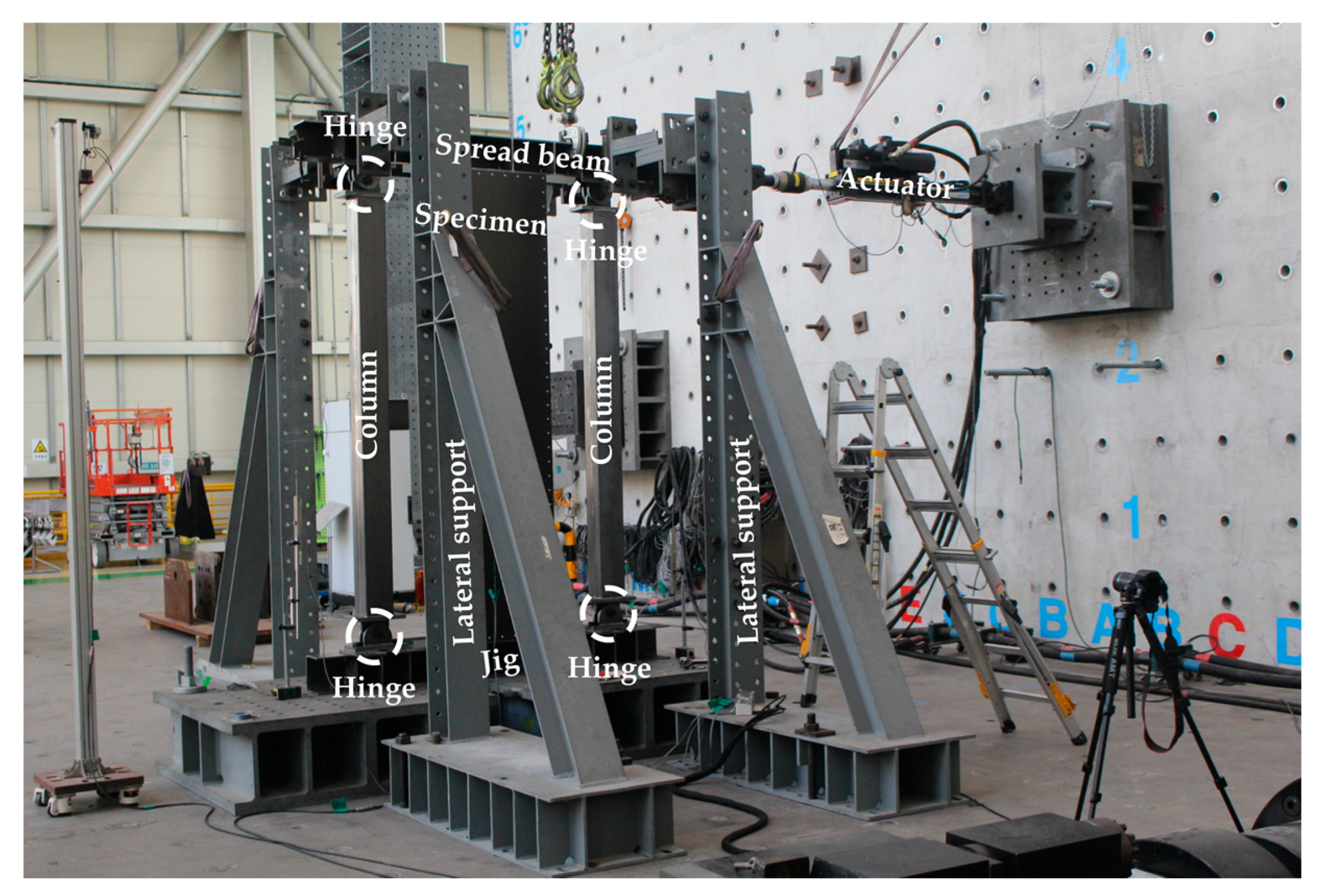
2.1. Test Protocol

Table 1 and Figure 3 show the test specimens and specimen components. Cyclic loading tests were performed on three IP specimens and a steel-sheathed panel (SSP) specimen. The SSP specimen was used as the standard of comparison for the IP specimens. The specimens reinforced with studs were named as the “integrated panel-inner stud” (IP-IS) and the “integrated panel-outer stud” (IP-OS), based on the position of the reinforcing stud.
For the SSP specimen, a 2440 mm high × 640 mm wide × 1.6 mm thick steel sheet was attached to the stud and track member with a single row of #10 screws ( ϕ 5.2 mm), as shown in Figure 4a. For the IP specimen, the track member and rip of the integrated member (C – 640 × 140 × 40 × 1.6) were joined using a single #10 screw, as shown in Figure 4b. The specimens were fabricated, such that the shear walls could be installed in the light gauge steel frame. The specimens consisted of an integrated member (or steel sheet and stud), four hold-downs, track members and reinforced studs. The specifications of the IP specimen and integrated panel-stud (IP-IS and IP-OS) specimens were identical, except for the addition of reinforcing studs, as shown in Figure 4c.
For the cyclic loading tests, a 200 kN actuator (maximum stroke = ± 200 mm) was attached to the left end of the spread beam (C – 180 × 150 × 9.0), and lateral supports were installed at two points on the loading jig, as shown in Figure 5. To fix the specimens and apply a loading force, the spread beams were joined to the hold-down of the panel with anchor bolts, and were installed above and below the panel. As the rigidity of the floor or roof elements in the light gauge steel frames are considerably higher than that of the shear panel, the spread beam is constrained by two columns (B – 150 × 150 × 4.5), with two hinged ends on the left and right sides of the specimens to match the displacement in the gravity direction of the spread beam. The testing rig was built with reference to studies conducted by Zeynalian et al. [24] and Mirzaei et al. [25], such that it behaves similarly to the panels in light gauge steel frames.
Moghimi and Ronagh [26] reported improvements in the racking resistance of shear walls, and the distortional buckling resistance of studs and chord members through cladding with gypsum boards. Further, the AISI Lateral Design standard [27] recommends a 30% increase in shear strength when using a wooden sheathing (or oriented strand board (OSB)) on one side, and a fully blocked gypsum board on the other side of those walls subject to wind and other types of in-plane loading. Therefore, dissimilar sheathing attached to the panel (e.g., OSB on the exterior face and gypsum board on the interior face) was ignored in this study.
Loading cycles were repeated six times for lateral drift ratios of ±0.375%, ±0.5%, and ±0.75%, four times for a lateral drift ratio of ±1.0%, and twice for lateral drift ratios of ±1.5%, ±2.0%, ±3.0%, ±4.0%, ±5.0%, ±6.0%, and ±7.0%. In this setup, a lateral drift ratio of 1.0% corresponded to a displacement of 24.4 mm. This loading protocol was adopted from the SAC loading protocol [28].

2.2. Material Properties

Table 2 summarizes the yield and tensile strengths of the IP components obtained in the three coupon tensile tests. The elongation of the 1.6 mm-thick members was measured at 35.6%, in accordance with the material properties (ratio of tensile strength to yield strength is not less than 1.08) specified in AISI S100.

3. Experimental Results

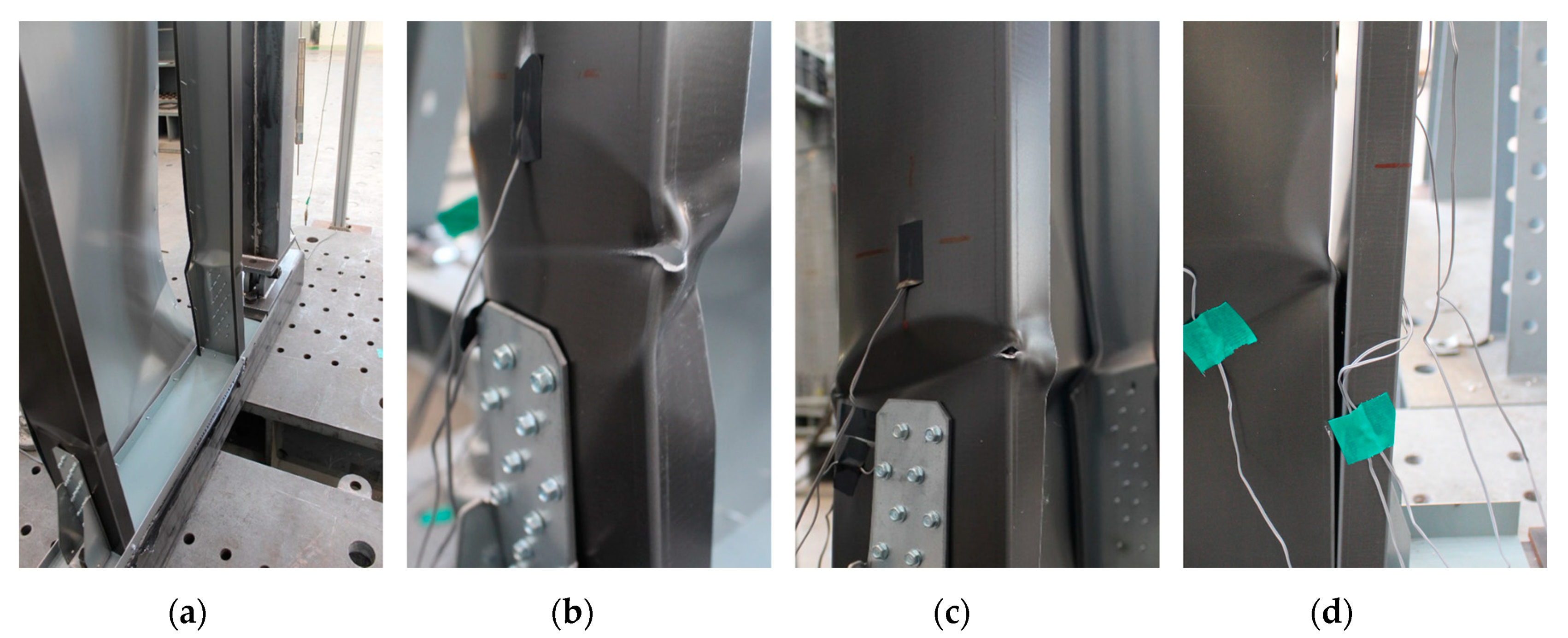
3.1. Lateral Load–Displacement Relationship and Failure Modes

Figure 6 and Figure 7 show the lateral load–drift ratio relationships and failure modes of the tested specimens. The energy equivalent elastic–plastic (EEEP) curves for the specimens are shown in Figure 6. The key parameters (the yield strength V y , yield displacement Δ y and ultimate displacement Δ u ) of the EEEP curves were defined in accordance with the American Society for Testing and Materials (ASTM) E2126-19 [29], as shown in Figure 8.
The integrated member specimens (IP, IP-IS, IP-OS) all showed local buckling at the bottom of the panel when subjected to loading force. The failures of the specimens were concentrated at the bottom of the panel, because the force exerted at the top of the panel by the actuator was lower than the force exerted by the jig at the bottom of the panel. Furthermore, failure occurred at greater displacements for the stud-reinforced specimens (IP-IS and IP-OS) than the non-reinforced specimen (IP). Finally, the screw pull-out failure of the SSP specimen occurred at a drift ratio of 4.0%. The screw is a point at which the load-carrying capacity changes dramatically, rendering it vulnerable to failure. However, no equivalent significant failure events were observed in the integrated member specimens.

3.2. Analysis and Comparison of Experimental Results

Table 3 summarizes the yield strength V y , maximum strengths V p e a k , displacement at the yield strength Δ y , displacement at the maximum strength Δ p e a k , ultimate displacement Δ u (displacement at 0.8 V p e a k after the lateral load reaches V p e a k ), elastic stiffness (the stiffness when the lateral load reaches 0.4 V p e a k in the load–drift ratio relationship) K e and ductility μ (= Δ u / Δ y ) of the specimens. The yield strength, V y , was determined using the equation
V y = ( Δ u Δ u 2 2 A K e ) K e
as suggested by ASTM E2126-19. For Δ u < 2 A / K e , it was assumed that V y = 0.85 V p e a k .

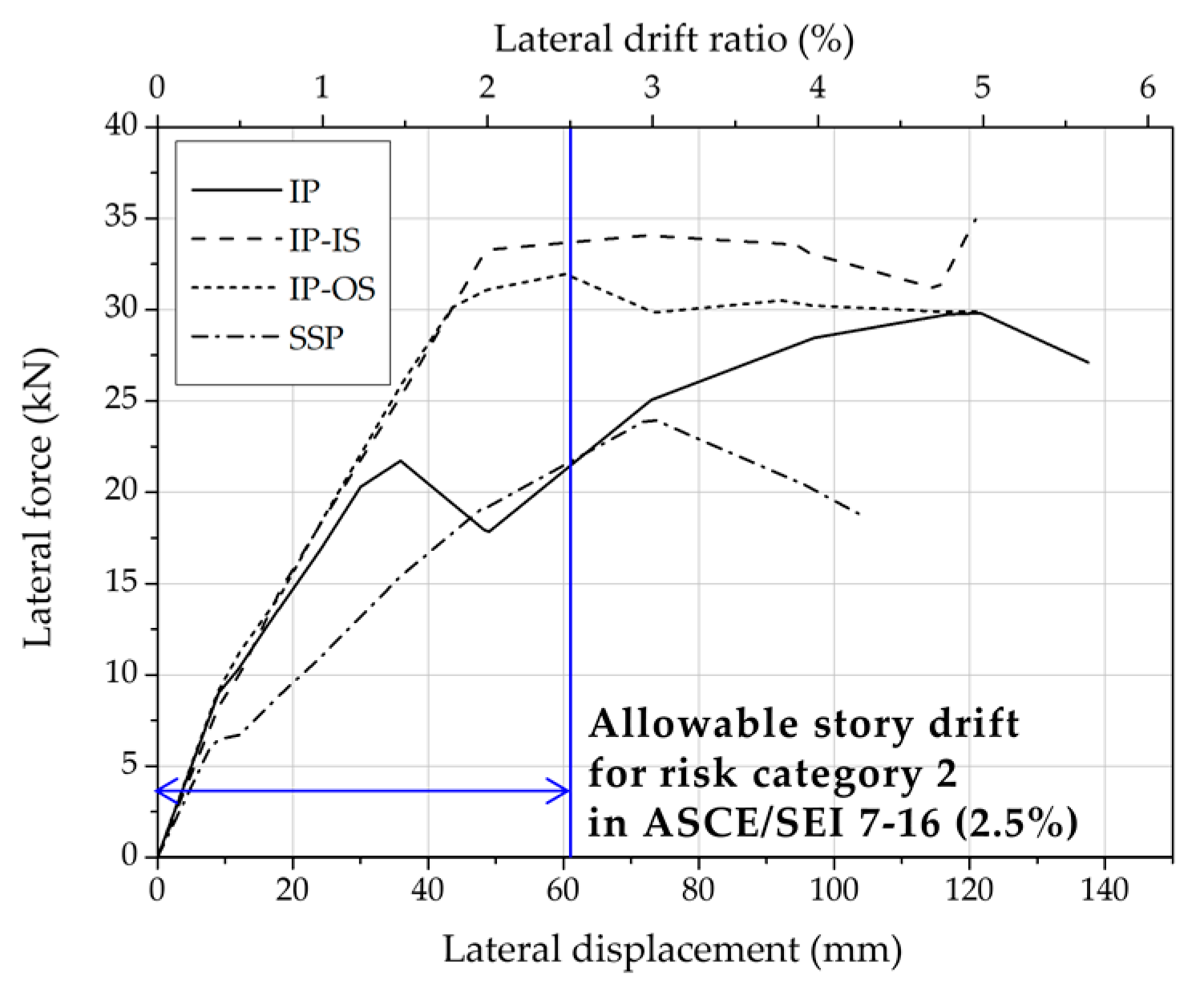
3.2.1. Load-Carrying Capacity

Table 3 lists the measured maximum strengths ( V p e a k ) of the tested specimens. The IP specimen shows 24.5% greater V p e a k values than the SSP specimen, because the screw pull-out failure that occurred in the SSP specimens prevented sufficient loading. Additionally, the IP-IS and IP-OS specimens show 19%–30% greater V p e a k values than those of the IP specimen. This is because the stud member was attached to the integrated member, increasing the capacity to accommodate compressive force and the bending moment in the left and right portions of the stud-reinforced specimens. Table 3 also lists the nominal strengths V n , A I S I of the specimens, as described in Section 1.3, calculated using the effective width method. The nominal strengths, indicated by dashed lines, are presented in Figure 6. The nominal strengths of IP, IP-IS and IP-OS specimens are 83%, 145%, and 160% of the yield strengths V y , respectively. The nominal strength V n , A I S I of the IP specimen is similar to the yield strength, although the web slenderness of the integrated member is nearly 400. The IP-IS and IP-OS specimens show 133% and 134% higher V n , A I S I values than those of the IP specimen, because the flanges—which are vulnerable to the bending of the integrated member—were reinforced. However, as a result of the test, the yield strengths V y of the stud-reinforced specimens (IP-IS and IP-OS) were 31% and 37% lower than the nominal strength V n , A I S I , indicating that the nominal strength prediction formula described in Section 1.3 is incorrect. The cause of this is analyzed in Section 3.2.5.

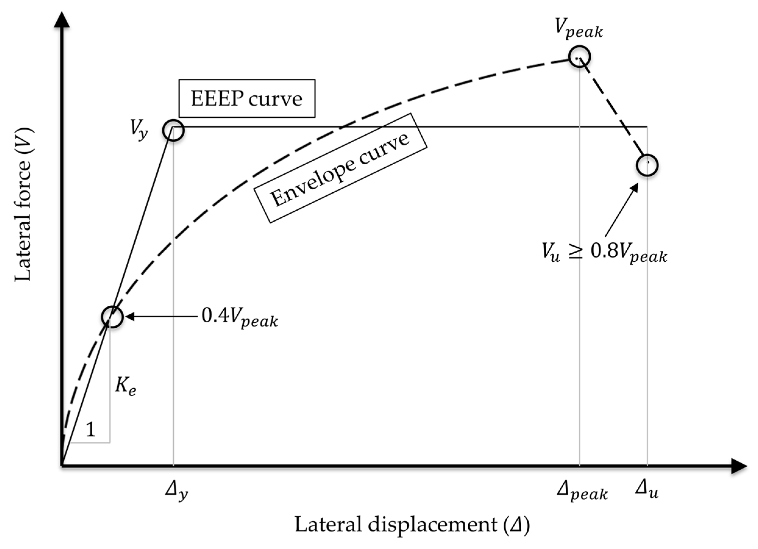
3.2.2. Yield Stiffness

Table 3 lists the measured elastic stiffness K e of the tested specimens. The elastic stiffness K e was defined in this study, as suggested by ASTM E2126-19. The SSP specimen shows a lower initial stiffness than the integrated member specimens, as shown in Figure 9. Since the steel sheet and studs were joined by screws in the SSP specimen, this stiffness was insufficient compared to that of the IP specimen. However, the increased initial stiffness of the IP specimens resulted in more rapid local buckling. The initial stiffnesses of the IP, IP-IS and IP-OS specimens are similar, as shown in Figure 9. This result indicates that there is little contribution to the elastic stiffness of the integrated member from the frame action.
According to the American Society of Civil Engineers (ASCE) standard (ASCE/SEI 7-16), the allowable story drift for risk category 2—which includes most structures, such as residential, commercial and industrial buildings—is 2.5%, as shown in Figure 9. Since the drift ratio of local buckling in the IP specimen was less than the allowable story drift in ASCE/SEI 7-16, it is necessary to reinforce the IP with a stud to make the IP specimen practicable for this application.

3.2.3. Deformation Capacity

Table 3 lists the displacement of the specimen at the yield strength ( Δ y ), maximum strength ( Δ p e a k ), ultimate strength ( Δ u ) and specimen ductility ( μ = Δ u / Δ y ). The ductility μ of the IP specimen is 110% greater than that of the SSP specimen. The integrated member specimens exhibit high deformation capacity with an ultimate displacement Δ u in the range of 4.7%–5.6%. Furthermore, the stud-reinforced specimens exhibit higher ultimate displacement and ductility than the IP-only specimen. Thus, the reinforcement of the integrated member with studs imparts strength, but slightly reduces the deformation capacity of the specimen.

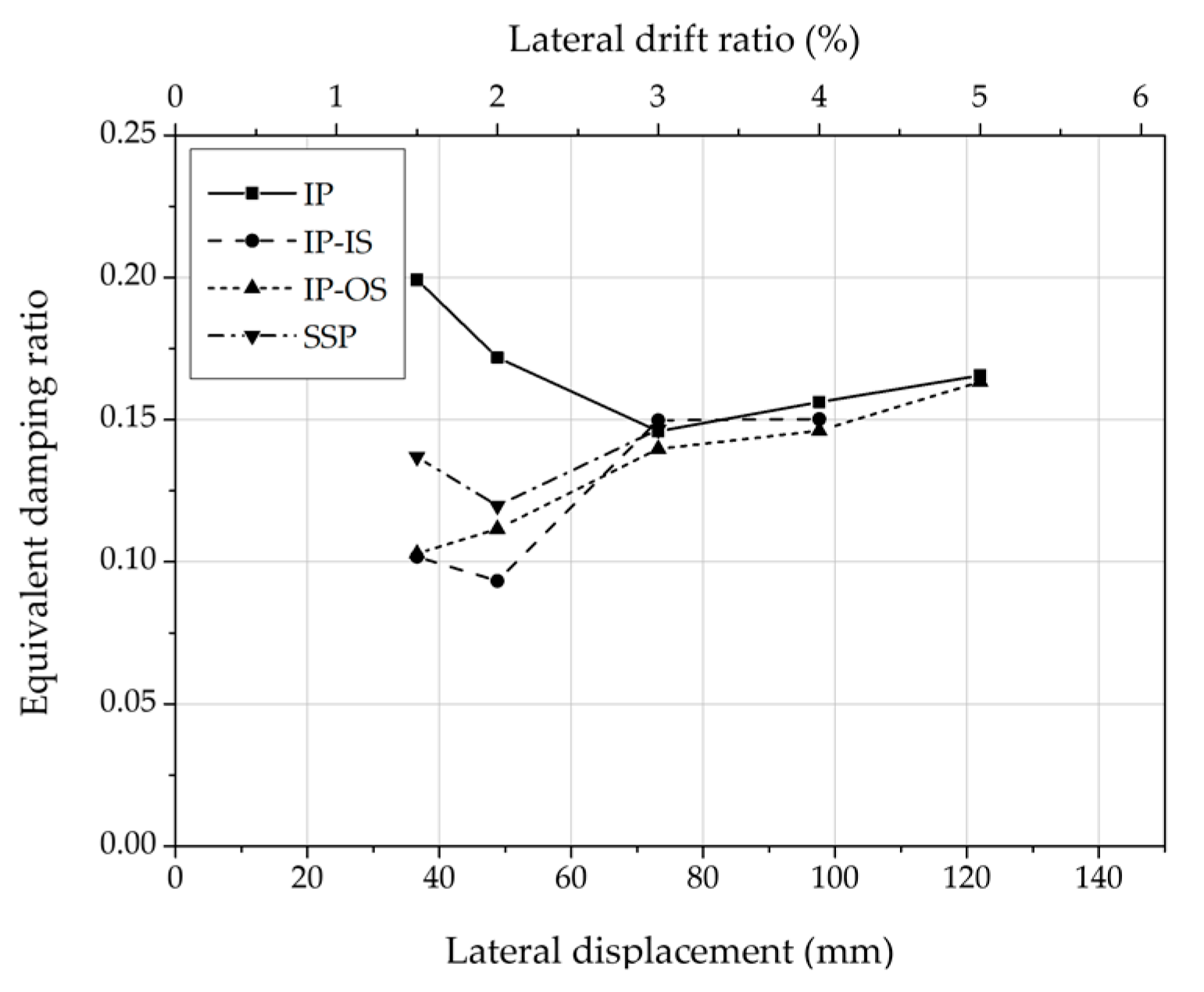
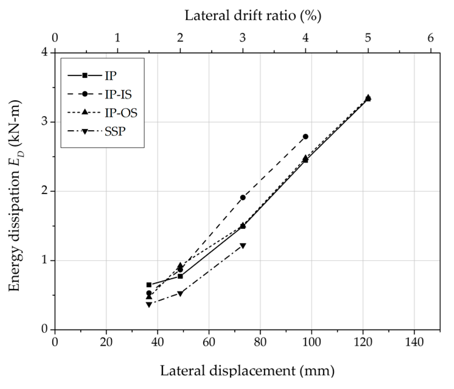
3.2.4. Equivalent Damping Ratio Per Load Cycle

Figure 10 and Figure 11 show the equivalent damping ratio ξ e q and the energy dissipation E D energy of the specimens per load cycle, as it varies with the drift ratio. The energy dissipation is defined as the area of the cyclic curve at the second loading cycle. The equivalent damping ratio ξ e q can be calculated as
ξ e q = E D 4 π E S o
where E S o is the maximum strain energy.
The IP specimen shows greater ξ e q values than the SSP specimen at drift ratios of 1.5% and 2.0% because the integrated member contributes to energy dissipation. The stud-reinforced specimens show low ξ e q values, because inelastic deformation did not occur at these drift ratios. Above a drift ratio of 3.0%, all the specimens show similar ξ e q values. However, the energy dissipation E D is the highest in the IP-IS specimen and the lowest in the SSP specimen, as shown in Figure 11. This is because the studs connected to the integrated member only in the hold-downs did not behave in combination with the integrated member, as shown in Figure 7d.

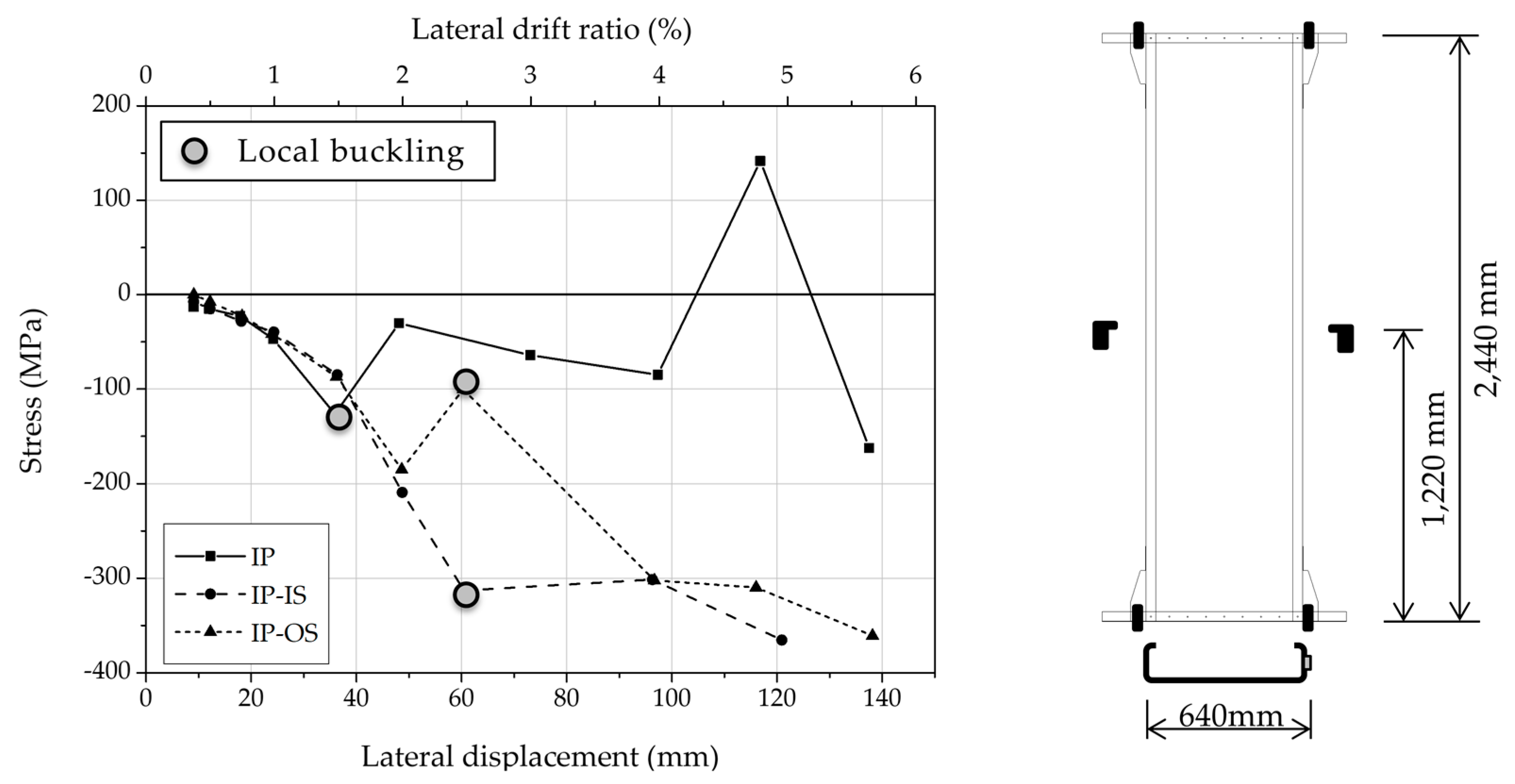
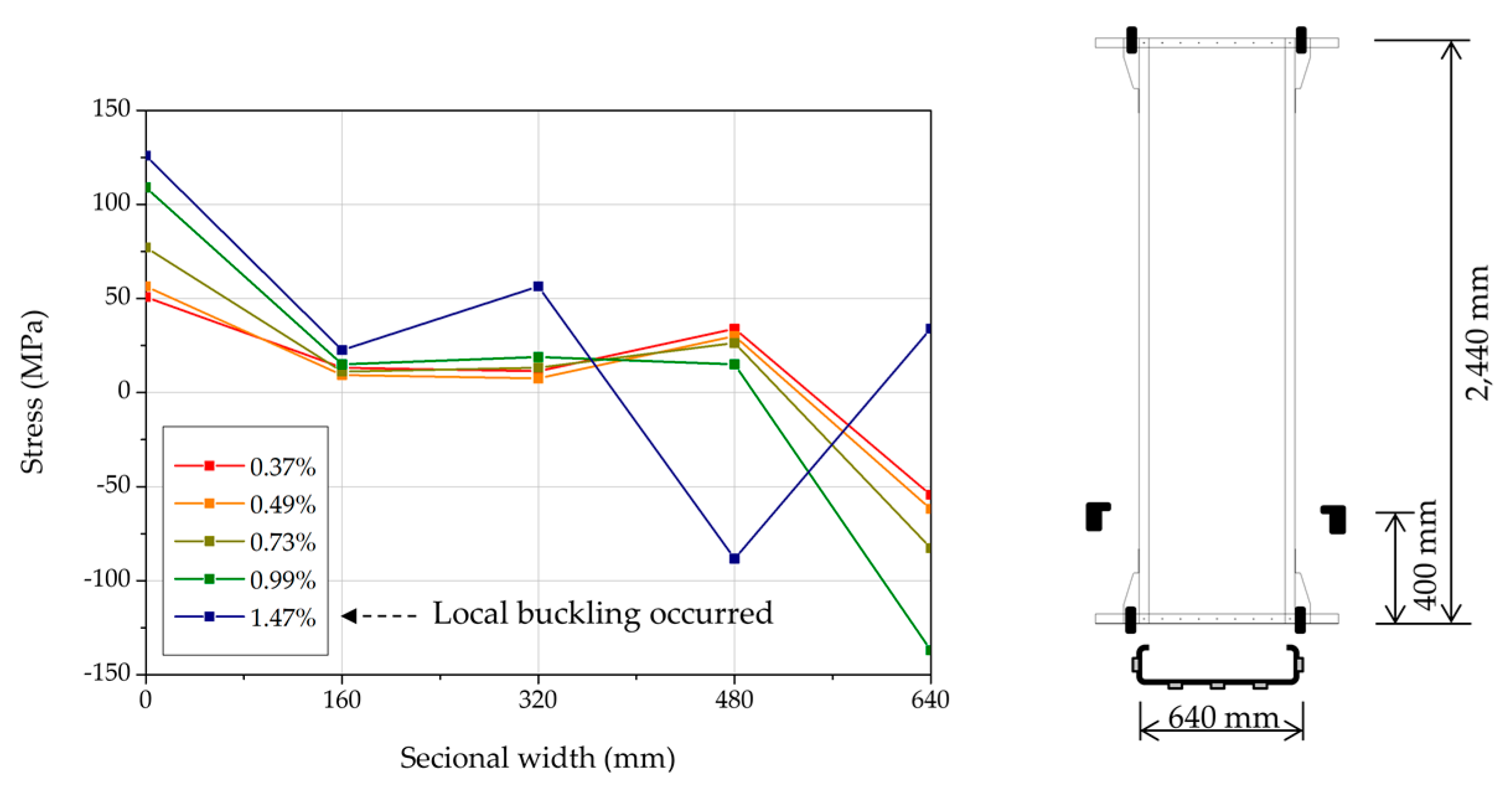
3.2.5. Strain Gauges Attached to the Integrated Member

Figure 12 and Figure 13 show the stresses measured with strain gauges attached to the integrated member. The stress value was calculated by multiplying the elastic modulus (203,000 MPa) with the strain measured using the strain gauge. The loci of Figure 12 and Figure 13 contain the peak loads from the first cycle of each phase of the cyclic loading.
The strain gauge, shown in Figure 12, was attached to the vertical direction at a height of 1220 mm ( h 0 + h 1 shown in Figure 2). The measured stresses exceed the yield strength at high lateral drift ratios in the stud-reinforced specimens. In the IP specimen, the measured stresses increase until local buckling occurred, but after the local buckling, the stresses are irregular. The IP-IS specimen exhibits higher and more stable stresses at a lateral drift ratio of 2.5% or more with local buckling than the IP-OS specimen. The reason for this tendency is that the IP-IS specimens behave in a combined manner with the integrated member and the stud, but the IP-OS specimens do not. The IP specimen shows a greater measured stress value at a lateral drift ratio of 1.5% than those of the stud-reinforced specimens. This is because the IP specimen has a smaller cross section than the stud-reinforced specimen.
The strain gauges, shown in Figure 13, were attached to the vertical direction at a height of 400 mm. Below a drift ratio of 1.0%, the stress distribution differs from the normal stress distribution for bending moment in the balanced lipped channel. Since the two columns with two hinged ends were installed on the left and right sides of the specimen to induce shear behavior, a tensile stress occurred at a point where the sectional width was 480 mm, which is where a compressive stress had to occur. These results are similar to the behavior of deep beams, because of the large width of the deep beam and the integrated member. Local buckling occurred at a 1.5% drift ratio, resulting in an irregular stress distribution.
Figure 13 also shows that local buckling occurs before sufficient stress is exerted on the section where local buckling of the integrated member occurs. The IP specimen temporarily lost their load due to local buckling, but the peak load increases at higher lateral drift ratios.
In the IP-IS and IP-OS specimens, local buckling occurs before sufficient stress is exerted on the section where local buckling occurred, similar to the IP specimen. However, as shown in Figure 6, the load tends to decrease after the local buckling of the IP-IS and IP-OS specimens. As listed in Table 3, the yield strengths V y of the stud-reinforced specimens (IP-IS and IP-OS) are 31% and 37% lower than the nominal strength V n , A I S I . Therefore, it is judged that other forces acted on the reinforcing studs in addition to the axial stress due to bending.

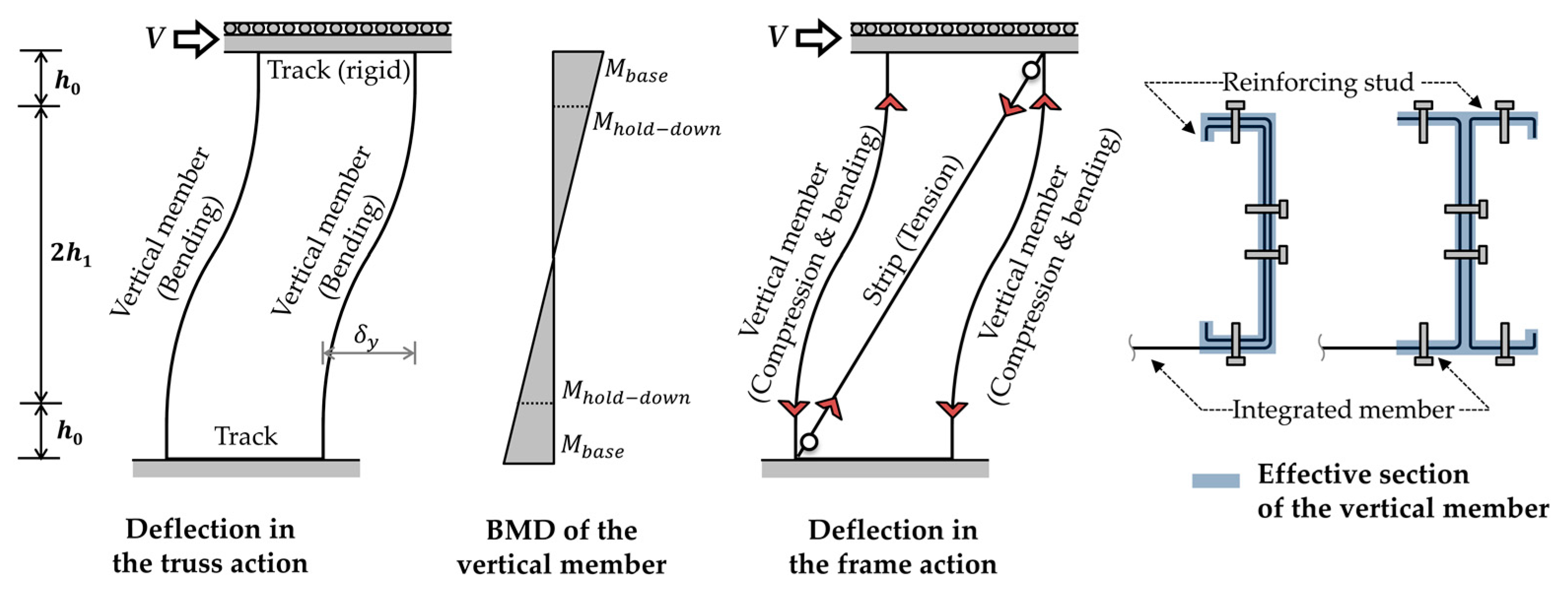
4. Proposed Method for Calculating Nominal Strength of an Integrated Panel with Reinforced Studs

4.1. Draft Prediction Equation for the Nominal Strength of an Integrated Panel with Reinforced Studs

To predict the nominal strength of the integrated panel, it is assumed that the integrated panel is composed of studs and steel sheets like in a steel-sheathed wall system. Yanagi and Yu [30] developed an analytical design method—known as the effective strip method—to predict the nominal strength of CFS-framed shear walls with steel sheet sheathing. This method uses the minimum strength of the screw connections to the effective strip and the effective width strength of the tension strip to determine the nominal strength of the wall system, after assuming the effective width according to the specifications of the steel-sheathed wall. Therefore, a sheet-sheathed wall system can be designed similar to a steel strap brace wall system. However, since the integrated panel is produced by bending one steel sheet, it is difficult to assume the effective width, because there are no screw joints. To solve this problem, we refer to the study by Mirzaei et al. [25], who tested and analyzed cold-formed steel strap-brace shear walls, and suggested that frame action should be considered in addition to truss action by strap braces.
When a lateral force is applied to the IP, the force mechanism acting within the integrated member can be expressed as a frame action and a truss action, as shown in Figure 14. V f and V t are the lateral forces in the frame and truss actions, respectively.
When considering frame action independently, there is no steel sheet (from the steel-sheathed wall system) in the integrated member. Thus, knowing the lateral stiffness, k f , and the yield displacement, δ y , V f can be calculated as follows:
V f = δ y k f = δ y · [ 2 · 12 E ( I f C ) h 3 ]
where E is the elastic modulus, I f is the moment of inertia of the flange portion of the integrated member with reinforced studs (see effective section of vertical member in Figure 14), C is a coefficient that helps reflect a change in the effective moment of inertia when a load is applied (as mentioned in Section 4.2, C is 0.09 and 0.24 for the inner and outer stud-reinforced integrated panels, respectively), and h is the height of the integrated member.
Using the calculated V f , the bending moment acting on the stud— M b a s e and M h o l d d o w n in Figure 14—can be evaluated as
M b a s e = V f h 4
M h o l d d o w n = M b a s e ( 0.5 h h o 0.5 h )
The truss action assumes the behavior of the integrated member equal to the steel strap-braced wall system or the effective strip method of steel-sheathed wall system. In truss action, tension is applied to the strip, and the resulting compressive force acts on the flange portion of the integrated member. As the effective width of strip is unknown, the bending moment acting on the stud must be used to predict the compressive force acting on the stud. According to AISI S100, the maximum allowable compressive force acting on the flange portion of the integrated member P ¯ r , m a x can be evaluated as follows:
P ¯ r , m a x = P n o ( 1 M ¯ r y M n y )
where P n o represents the nominal capacity term for axial compression, M ¯ r y is the required flexural demand about the y-axis such that M ¯ r y = M h , and M n y is the nominal bending capacity about the y-axis.
Therefore, the lateral force V t , at which the maximum tensile force does not cause failure of the flange, acting on the strip of the panel can be expressed as
V t = P ¯ r , m a x cot θ
Finally, the proposed nominal strength of the integrated panel with reinforced studs V n , p can be expressed as
V n , p = V f + V t

4.2. Comparison of Prediction Equation and Test Results for the Integrated Panel with Reinforced Studs

Figure 15 shows the variation in the average yield strength ( V y , a v g )-to-proposed nominal strength ( V n , p ) with the coefficient of the stud-reinforced specimens at yield displacement Δ y . The coefficient C values at nominal strengths V n , p consistent with the average yield strength V y , a v g are 0.09 and 0.24 for the IP-IS and IP-OS specimens, respectively. The reasons for the low value of C are as follows: (1) the moment of inertia is proportional to the third power of the length in the bending direction of the member; (2) the effective section of the integrated panel is conservatively assumed, as shown in Figure 14; (3) the studs connected to the integrated member did not behave in combination with the integrated member in the IP-OS specimen, as shown in Figure 7d. The cross section of the integrated member, the cross section of the reinforcing studs, and the position of the reinforcing studs, may be factors influencing the coefficient C . Although it is unclear at this time, because only two specimens were analyzed, we believe a finite element analysis of the various models will provide a clearer correlation. In addition, as the experiment was performed on only one specimen per type of the integrated panel, the proposed equation in Section 4.1 is not perfect; however, this equation is meaningful, as it reflects the failure aspects of the specimens, such as the location of the local buckling.

5. Summary and Conclusions

This paper proposes an integrated panel that can replace studs and steel sheet in a steel-sheathed wall system. The integral panels are more workable than the steel-sheathed wall system. We experimentally verified that they exhibit stable structural performance when reinforcing the integrated member with studs. The findings of the study are summarized as follows.
  • The yield strength V y , maximum strengths V p e a k , elastic stiffness K e , ductility μ and equivalent damping ratio ξ e q of SSP, IP, IP-IS and IP-OS specimens were compared. The IP specimen showed better structural performance than the SSP specimen. Considering the allowable story drift, reinforcing integrated members with studs can increase the yield strength, and local buckling occurred at high drift ratios. When reinforcing the integrated member with studs, it is recommended to reinforce the studs inside, not outside of, the integrated member, so that the studs behave in combination.
  • Assuming that the integrated member behaves like a cantilever beam, the nominal strengths V n , A I S I of the IP, IP-IS and IP-OS specimens were 83%, 145% and 160% of the yield strengths V y , respectively. The nominal strength V n , A I S I of the IP specimens appeared to be similar to the yield strength V y , although the web slenderness of the integrated member was nearly 400. Since the nominal strength V n , A I S I of the stud-reinforced specimens (IP-IS and IP-OS) were 45% and 60% higher than the yield strength V y , respectively, the assumption that the integrated panel behaves like a cantilever beam, was found to be incorrect.
  • To predict the nominal strength of the integrated panel with reinforced stud, a draft prediction equation was proposed. The proposed nominal strength V n , p coincided with the average yield strength V y , a v g at the yield displacement when the values of the coefficient C that reflects the changes in the effective moment of inertia when loaded are 0.09 and 0.24 in the IS-IS and IP-OS specimens, respectively. The cross-section of the integral member, the cross-section of the reinforcing studs, and the position of the reinforcing studs, are considered to be factors influencing the coefficient C . The proposed equation is meaningful, as it reflects the failure aspects of the specimens, such as the location of local buckling. A finite element analysis of the various models may help to accurately define the coefficient C .
This research can be useful when reinforcing parts with a high web slenderness ratio in light gauge steel frames. In future studies, further consideration should be given to the fact that the seismic performance of the panel may be significantly affected when an axial load is applied to the panel, or when dissimilar sheathing is attached to the panel.

Author Contributions

D.-Y.L. and B.-H.C. conceived and designed the experiments; D.-Y.L., D.-I.J., J.-S.L. and K.-W.L. performed the experiments; D.-Y.L. analyzed the data; D.-Y.L. manily wrote this article; B.-H.C. revised this article and contribute to the analysis; All authors have read and agreed to the published version of the manuscript.

Funding

This research was funded by the National Research Foundation of Korea, grant number NRF-2016 R1D1A1B01010615.

Conflicts of Interest

The authors declare no conflict of interest.

References

  1. Chini, S.A.; Gupta, K. A comparison between steel and wood residential framing systems. J. Construct. Educ. Summer 1997, 2, 133–145. [Google Scholar]
  2. Yang, W.; Yang, Q. Study on the dynamic characteristics of light steel residential structural system. Engineering 2017, 9, 591–598. [Google Scholar] [CrossRef] [Green Version]
  3. Yong, Y.; Yunpeng, C.; Yongjun, D.; Bin, X.; Xiaoyan, G. Numerical simulation of the cold-formed thin-walled steel structure system. Build. Struct. 2011, 2, 41–45. [Google Scholar]
  4. Barton, A.D. Performance of Steel Framed Domestic Structures Subject to Earthquake Loads. Ph.D. Thesis, University of Melbourne, Melbourne, Australia, 1997. [Google Scholar]
  5. Von Karman, T. The strength of thin plates in compression. Trans. ASME 1932, 54, 53–57. [Google Scholar]
  6. Winter, G. Strength of thin steel compression flanges. Trans. ASCE 1947, 112, 527. [Google Scholar]
  7. AISI S100. North American Specification for the Design of Cold-Formed Steel Structural Members; American Iron and Steel Institute: Washington, DC, USA, 2016. [Google Scholar]
  8. Winter, G. Commentary on the 1968 Edition of the Specification for the Design of Cold-Formed Steel Structural Members; American Iron and Steel Institute: New York, NY, USA, 1970. [Google Scholar]
  9. LaBoube, R.A.; Yu, W.W. Structural behavior of beam webs subjected primarily to shear stress. In Civil Eng. Study Struct. Ser.; Department of Civil Engineering, University of Missouri: Rolla, MS, USA, 1978; Volume 78–2. [Google Scholar]
  10. LaBoube, R.A.; Yu, W.W. Structural behavior of beam webs subjected to a combination of bending and shear. In Civil Eng. Study Struct. Ser.; Department of Civil Engineering, University of Missouri: Rolla, MS, USA, 1978; Volume 78–3. [Google Scholar]
  11. LaBoube, R.A.; Yu, W.W. Bending strength of webs of cold-formed steel beams. J. Struct. Divis. 1982, 108, 1589–1604. [Google Scholar]
  12. Hetrakul, N.; Yu, W.W. Structural behavior of beam webs subjected to web crippling and a combination of web crippling and bending. In Civil Eng. Study Struct. Ser.; Department of Civil Engineering, University of Missouri: Rolla, MS, USA, 1978; Volume 78–4. [Google Scholar]
  13. Hetrakul, N.; Yu, W.W. Cold formed steel I-beams subjected to combined bending and web crippling. In Proceedings of the International Conference (2nd ed.), University of Strathclyde, Glasgow, UK, 3–6 April 1979; pp. 413–426. [Google Scholar]
  14. Phung, N.; Yu, W.W. Structural behavior of longitudinally reinforced beam webs. In Civil Eng. Study Struct. Ser.; Department of Civil Engineering, University of Missouri: Rolla, MS, USA, 1978; Volume 78–6. [Google Scholar]
  15. Phung, N.; Yu, W.W. Structural behavior of transversely reinforced beam webs. In Civil Eng. Study Struct. Ser.; Department of Civil Engineering, University of Missouri: Rolla, MS, USA, 1978; Volume 78–5. [Google Scholar]
  16. DaBreo, J.; Rogers, C.A. Steel Sheathed Shear Walls Subjected to Combined Lateral and Gravity Loads; Department of Civil Engineering and Applied Mechanics, McGill University: Montreal, Canada, 2012. [Google Scholar]
  17. DaBreo, J.; Balh, N.; Ong-Tone, C.; Rogers, C.A. Steel sheathed cold-formed steel framed shear walls subjected to lateral and gravity loading. Thin-Walled Struct. 2014, 74, 232–245. [Google Scholar] [CrossRef]
  18. Ong-Tone, C. Tests and Evaluation of Cold-Formed Steel Frame; Department of Civil Engineering and Applied Mechanics, McGill University: Montreal, Australia, 2009. [Google Scholar]
  19. Rogers, C.A.; Balh, N.; Ong-Tone, C.; Shamim, I.; DaBreo, J. Development of seismic design provisions for steel sheet sheathed shear walls. In Proceedings of the Structures Congress 2011, Las Vegas, NV, USA, 14–16 April 2011; pp. 676–687. [Google Scholar]
  20. Hong, S.G.; Cho, B.H.; Chung, K.S.; Moon, J.H. Behavior of framed modular building system with double skin steel panels. J. Construct. Steel Res. 2011, 67, 936–946. [Google Scholar] [CrossRef]
  21. Tian, H.W.; Li, Y.Q.; Yu, C. Testing of steel sheathed cold-formed steel trussed shear walls. Thin-Walled Struct. 2015, 94, 280–292. [Google Scholar] [CrossRef]
  22. Wang, J.; Wang, W.; Xiao, Y.; Yu, B. Cyclic test and numerical analytical assessment of cold-formed thin-walled steel shear walls using tube truss. Thin-Walled Struct. 2019, 134, 442–459. [Google Scholar] [CrossRef]
  23. AISI. Specification for the Design of Cold-formed Steel Structural Members; American Iron and Steel Institute: Washington, DC, USA, 1989. [Google Scholar]
  24. Zeynalian, M.; Ronagh, H.R.; Hatami, S. Seismic characteristics of K-braced cold-formed steel shear walls. J. Construct. Steel Res. 2012, 77, 23–31. [Google Scholar] [CrossRef]
  25. Mirzaei, A.; Sangree, R.H.; Velchev, K.; Comeau, G.; Balh, N.; Rogers, C.A.; Schafer, B.W. Seismic capacity-based design of narrow strap-braced cold-formed steel walls. J. Construct. Steel Res. 2015, 115, 81–91. [Google Scholar] [CrossRef]
  26. Moghimi, H.; Ronagh, H.R. Performance of light-gauge cold-formed steel strap-braced stud walls subjected to cyclic loading. Eng. Struct. 2009, 31, 69–83. [Google Scholar] [CrossRef]
  27. AISI S213. North American Standard for Cold-Formed Steel framing—Lateral Design; American Iron and Steel Institute: Washington, DC, USA, 2009. [Google Scholar]
  28. Clark, P.; Frank, K.; Krawinkler, H.; Shaw, R. Protocol for Fabrication, Inspection, Testing, and Documentation of Beam-Column Connection Tests and Other Experimental Specimens; Rep. No. SAC/BD-97; SAC Joint Venture: Berkeley, CA, USA, 1997. [Google Scholar]
  29. ASTM E2126-19. Standard Test Methods for Cyclic (Reversed) Load Test for Shear Resistance of Vertical Elements of the Lateral Force Resisting Systems for Buildings; ASTM International: West Conshohocken, PA, USA, 2019. [Google Scholar]
  30. Yanagi, N.; Yu, C. Effective strip method for the design of cold-formed steel framed shear wall with steel sheet sheathing. J. Struct. Eng. 2013, 140, 04013101. [Google Scholar] [CrossRef]
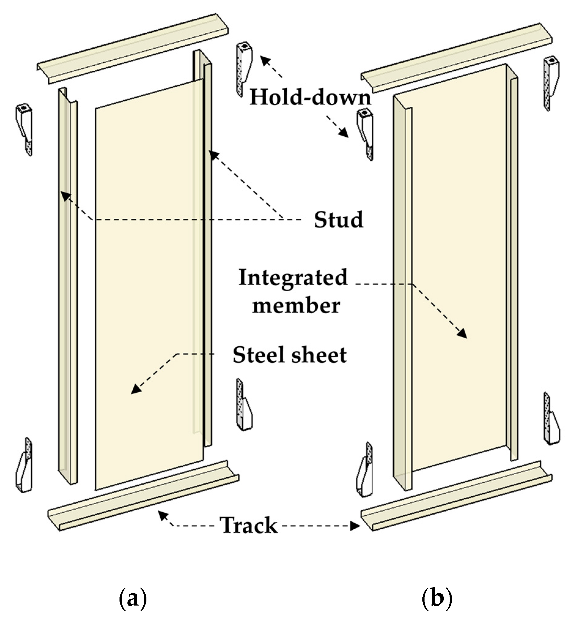
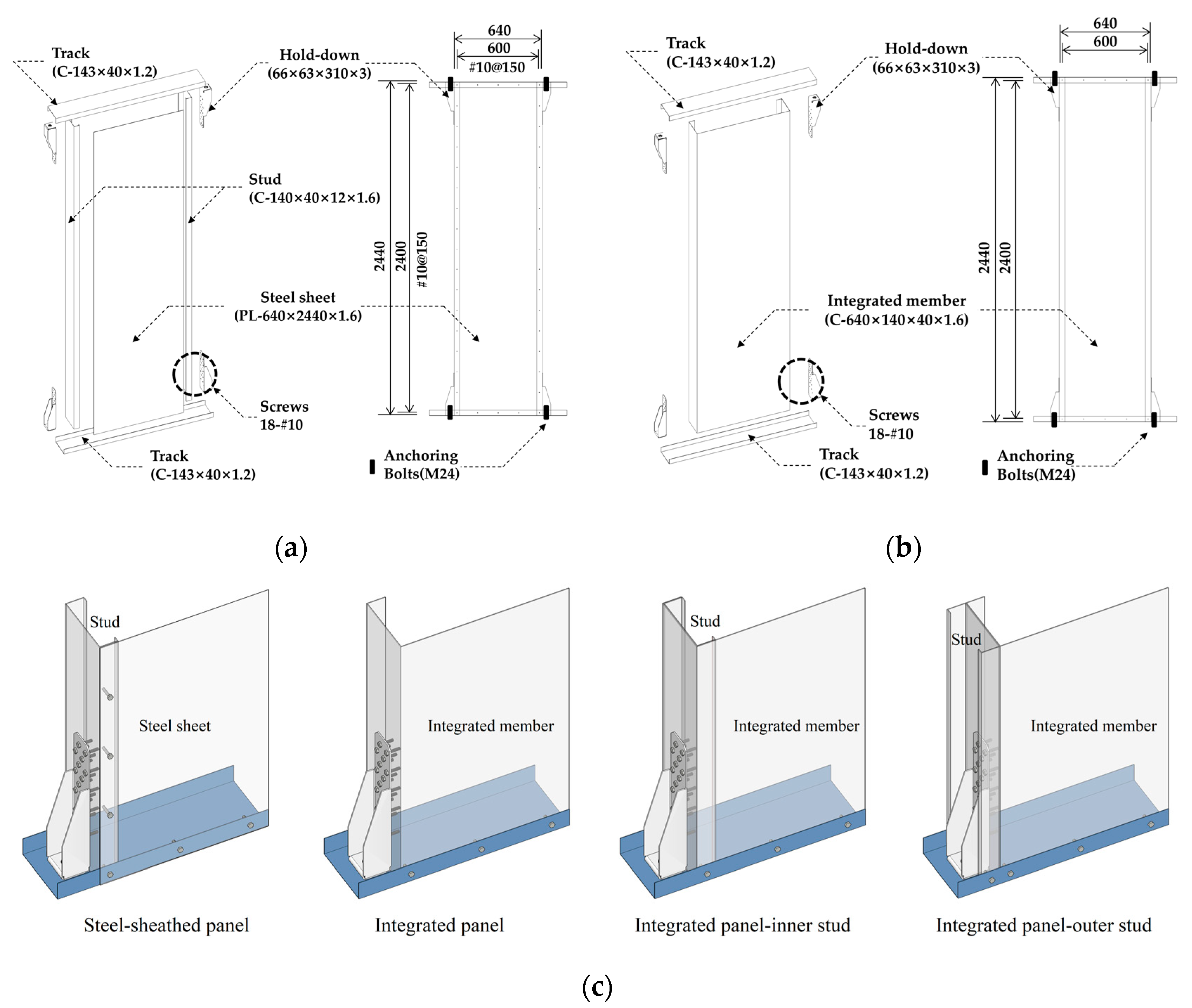
Figure 1. Conceptual diagram of an integrated panel system derived from a steel-sheathed wall system: (a) Steel-sheathed wall system, (b) Integrated panel system.
Applsci 10 01649 g001
Figure 2. Free body diagram of an integrated panel ( h o is the height of the hold-down, and h 1 is half the height of the integrated member except the hold-down).
Applsci 10 01649 g002
Figure 3. Specimen components: (a) Steel-sheathed panel, (b) Integrated panel, (c) Integrated panel-inner stud, (d) Integrated panel-outer stud.
Applsci 10 01649 g003
Figure 4. Configurations and details (mm): (a) Steel-sheathed panel, (b) Integrated panel, (c) Lower left side of the specimens. Note that the specifications of the integrated panel-stud specimens are identical except for the addition of reinforcing studs.
Applsci 10 01649 g004
Figure 5. Test set-up.
Applsci 10 01649 g005
Figure 6. Lateral load–drift ratio relationships and failure modes of specimens: (a) The steel-sheathed panel (SSP) specimen, (b) The integrated panel-inner stud (IP) specimen, (c) The integrated panel-inner stud (IP-IS) specimen, (d) The integrated panel-outer stud (IP-OS) specimen.
Applsci 10 01649 g006
Figure 7. Failure modes of specimens: (a) Screw pull-out of the steel-sheathed panel (SSP) specimen, (b) Local buckling and tearing of the integrated panel-inner stud (IP) specimen, (c) Local buckling and tearing of the integrated panel-inner stud (IP-IS) specimen, (d) Local buckling of the integrated panel-outer stud (IP-OS) specimen.
Applsci 10 01649 g007
Figure 8. Definition of key parameters according to the American Society for Testing and Materials (ASTM) E2126-19. The energy equivalent elastic–plastic (EEEP) curve is the energy equivalent elastic–plastic curve.
Applsci 10 01649 g008
Figure 9. Comparison of the average envelope curves of the specimens.
Applsci 10 01649 g009
Figure 10. Variation in the equivalent damping ratio per load cycle with drift ratio.
Applsci 10 01649 g010
Figure 11. Variation in the energy dissipation per load cycle with drift ratio.
Applsci 10 01649 g011
Figure 12. Variation in the stress with drift ratio measured using the strain gauge attached to the vertical direction at a height of 1220 mm at the center of the flange of the integrated panel.
Applsci 10 01649 g012
Figure 13. Variation in the stress at the section measured using strain gauges attached to the vertical direction at a height of 400 mm with the drift ratio of the IP specimen.
Applsci 10 01649 g013
Figure 14. Force mechanism acting within the integrated panel with reinforced studs.
Applsci 10 01649 g014
Figure 15. Variation in the average yield strength-to-proposed nominal strength with the coefficient of the stud-reinforced specimens at yield displacement.
Applsci 10 01649 g015
Table 1. Test specimens (mm).
SpecimensMain ComponentStud
SSP
(Steel-sheathed panel)
Steel sheet
(PL – 640 × 2440 × 1.6)
C – 140 × 40 × 12 × 1.6
IP
(integrated panel)
Integrated member
(C – 640 × 140 × 40 × 1.6)
-
IP-IS
(integrated panel-inner stud)
Inner Stud
(C – 137 × 40 × 12 × 1.6)
IP-OS
(integrated panel-outer stud)
Outer Stud
(C – 140 × 40 × 12 × 1.6)
Table 2. Yield and tensile strengths of cold-formed steel (CFS) components of the integrated panel.
SteelNumber of Coupon TestsThickness (mm)Maximum Yield/Tensile Strengths (MPa)Minimum Yield/Tensile Strengths (MPa)Average Yield/Tensile Strengths (MPa)
Track31.2324.4/352.6323.6/352.3323.9/352.4
Integrated member, steel sheet, and stud31.6324.6/375.0323.1/374.9324.0/374.9
Table 3. Summary of key parameters for the tested specimens.
SpecimensTest ResultsPredictionComparison
V y (kN) V p e a k (kN) Δ y (mm (%)) Δ p e a k (mm (%)) Δ u (mm (%)) K e (kN/mm) μ V n , A I S I   (kN) V n , A I S I   / V y
SSP+20.123.549.7 (2.0)72.8 (3.0)103.7 (4.3)0.402.09--
-23.924.646.0 (1.9)73.0 (3.0)81.2 (3.3)0.521.76
IP+23.728.138.1 (1.6)120.0 (4.9)137.5 (5.6)0.623.6120.60.87
-26.231.827.1 (1.1)124.4 (5.1)121.6 (5.0)0.974.480.79
IP-IS+34.436.952.7 (2.2)61.8 (2.5)120.9 (5.0)0.652.2948.11.40
-32.134.936.4 (1.5)48.7 (2.0)115.4 (4.7)0.883.171.50
IP-OS+29.932.650.9 (2.1)61.6 (2.5)138.2 (5.7)0.592.7248.41.62
-30.635.026.6 (1.1)44.1 (1.8)121.0 (5.0)1.154.551.58
SSP: steel sheath panel; IP: integrated panel; IP-IS: IP-inner stud; IP-OS: IP-outer stud. * V n , A I S I is calculated using the equation (2) in Section 1.3.

