
An Optimization Study on the Hull Form and Stern Appendage for Improving Resistance Performance of a Coastal Fishing Vessel


Abstract
:Featured Application
Abstract
1. Introduction
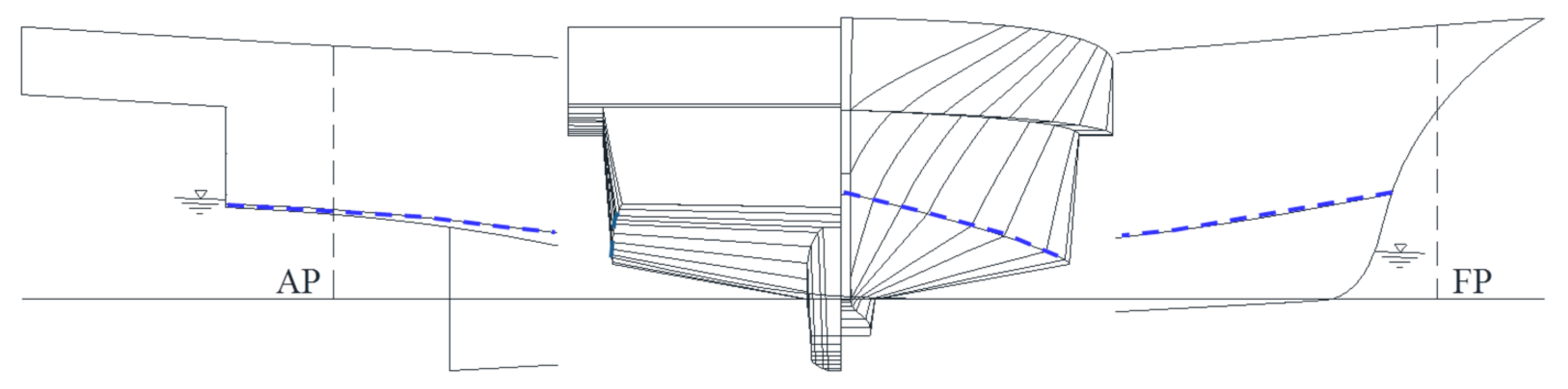
2. Objective Ship
3. Computational Method
3.1. CFD
3.1.1. Governing Equations
3.1.2. Computational Methods
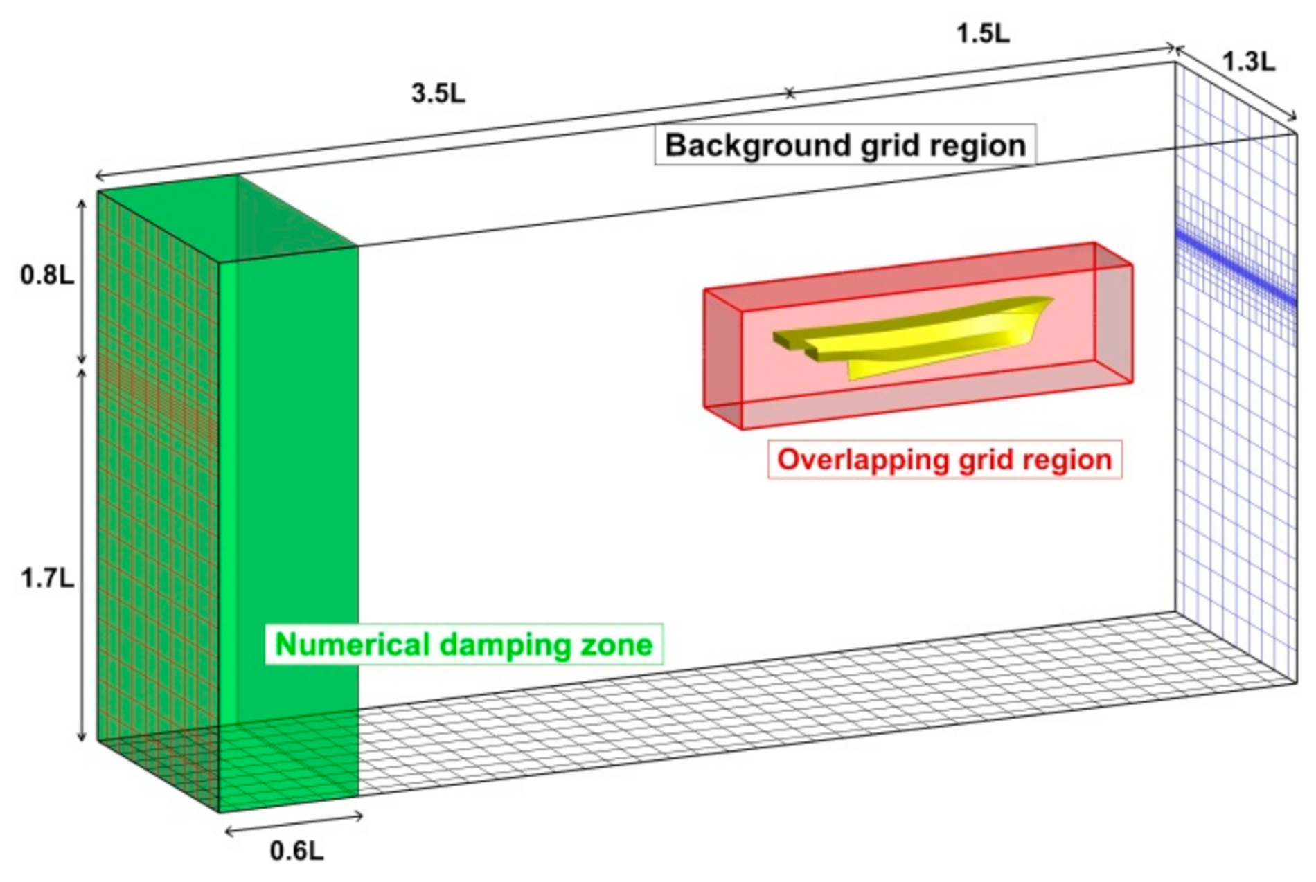
3.1.3. Computational Domain and Boundary Conditions
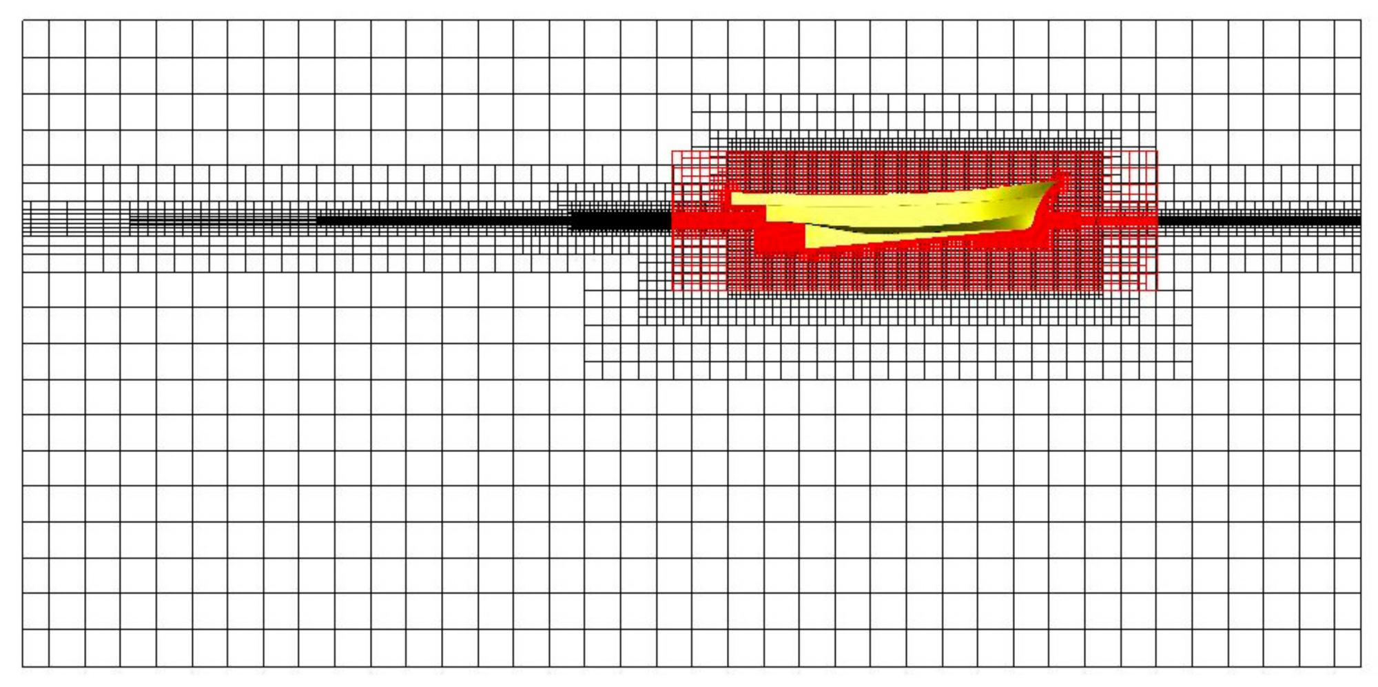
3.1.4. Grid Generation
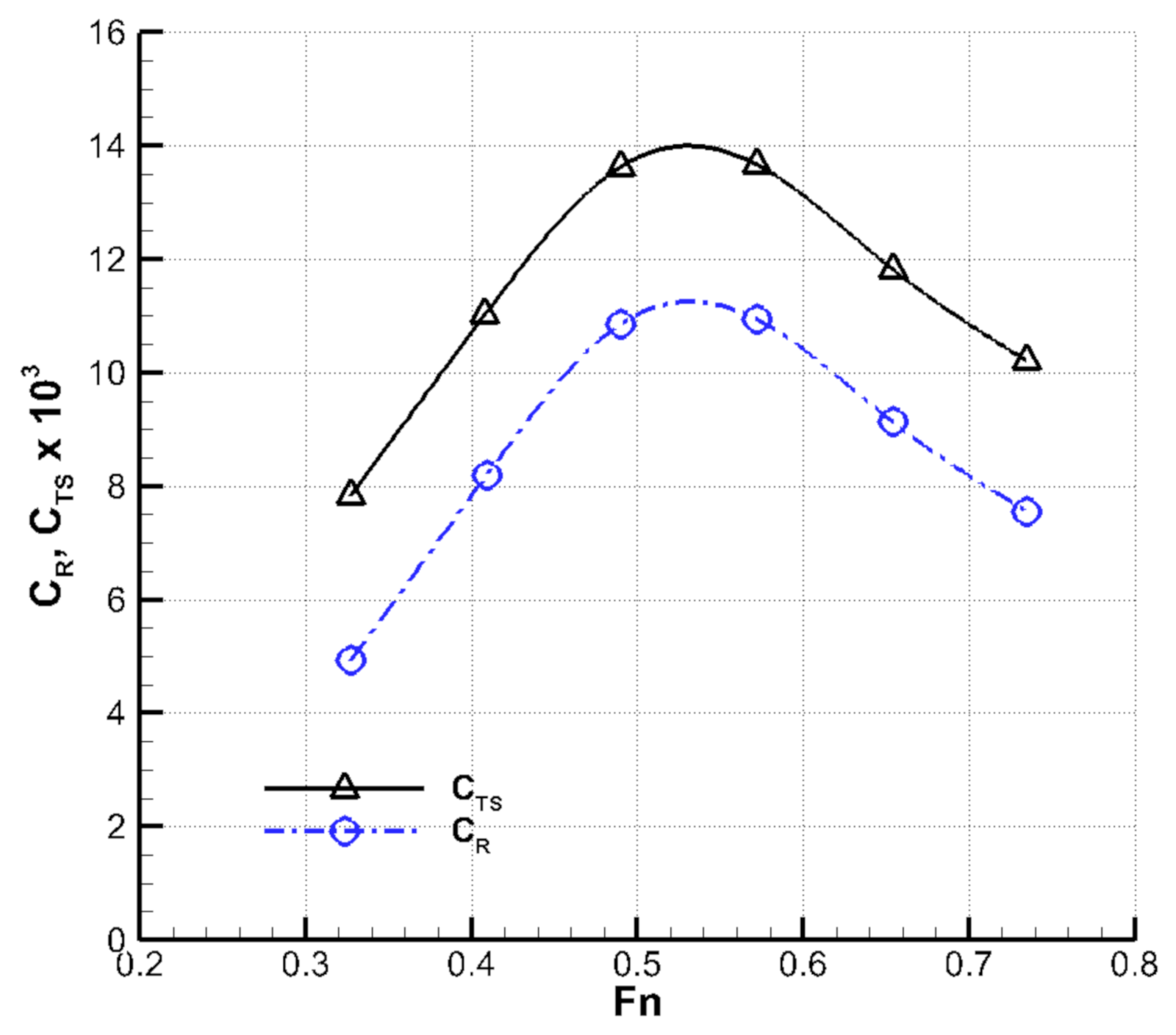
3.2. Validation and Verification of CFD Results
4. Results
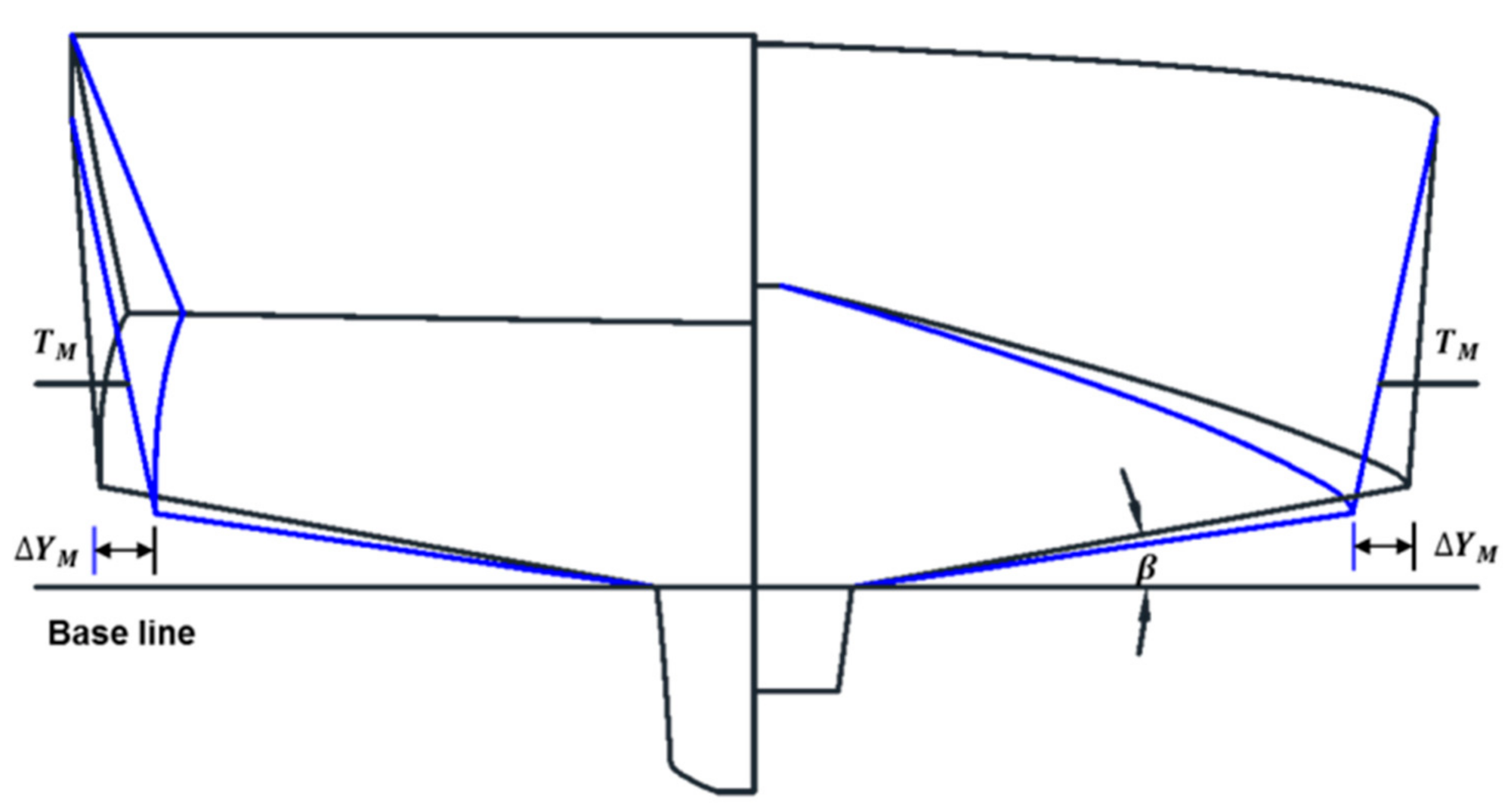
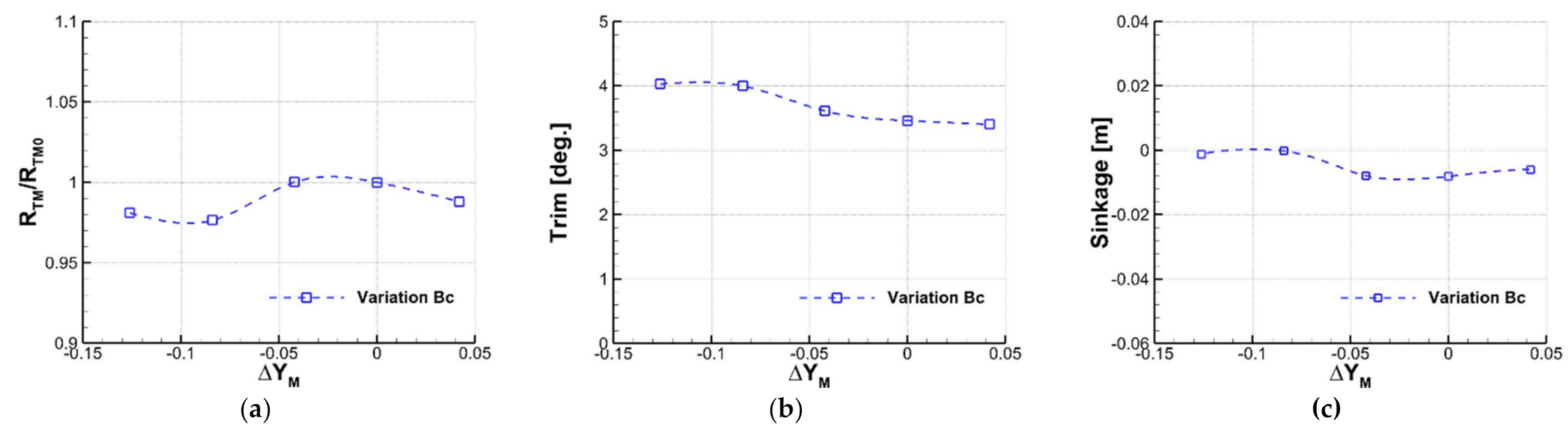
4.1. Bow Hull form Variation
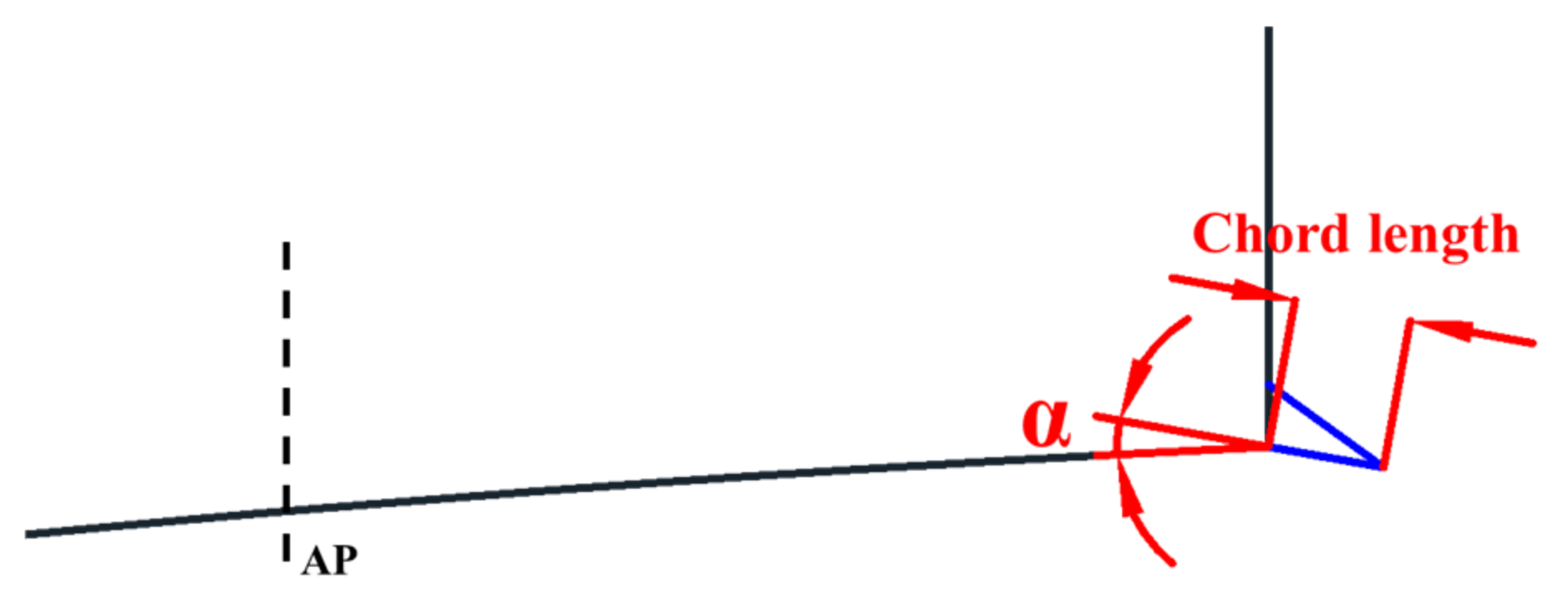
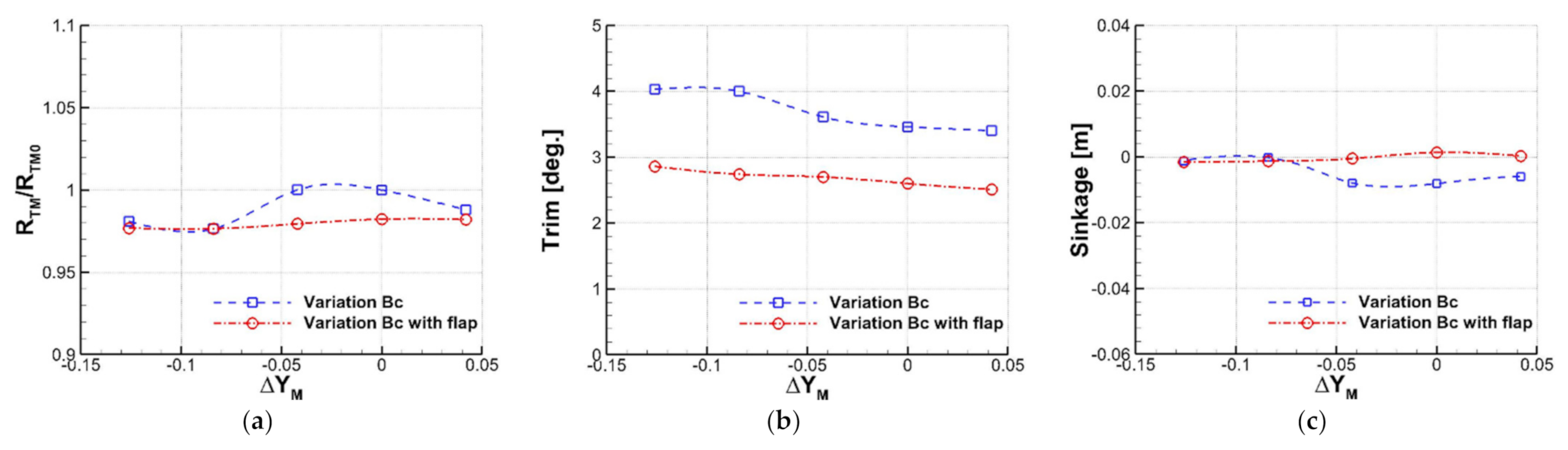
4.2. Effect of Stern Appendage
5. Conclusions
Author Contributions
Funding
Institutional Review Board Statement
Informed Consent Statement
Conflicts of Interest
References
- Doust, D.J. Trawler Forms with Bulbous Bows. In Fishing Boats of the World: 2—Sea Behavior; Fishing News Ltd.: London, UK, 1960; pp. 445–452. [Google Scholar]
- Korea Institute of Machinery and Materials. Research on the Modernization of Small Fishing Boats; KIMM: Daejon, Korea, 1984. (In Korean) [Google Scholar]
- Korea Fishing Vessel Society. Report on the Development of Standard Fishing Vessels; KFVS: Seoul, Korea, 1994. (In Korean) [Google Scholar]
- Kim, I.S.; Go, D.G.; Park, D.W. A study on hull dorm design for small fishing vessels. J. Korean Soc. Mar. Eng. 2017, 41, 316–322. (In Korean) [Google Scholar]
- Kang, D.S.; Yu, J.W.; Lee, Y.G. A Study on the Hull Form Design with Minimum Resistance for Domestic Coastal Fishing Boats. J. Soc. Nav. Arch. Korea 2007, 44, 349–359. (In Korean) [Google Scholar] [CrossRef] [Green Version]
- Ha, Y.J.; Lee, Y.G.; Lee, S.H.; Kim, S.H.; Yu, J.W.; Back, Y.S.; Bae, D.G. Improvement of the Resistance Performance for a G/T 29ton Class Coastal Angling Fishing Boat based on Hull-form Design. J. Soc. Nav. Arch. Korea 2014, 51, 521–529. (In Korean) [Google Scholar] [CrossRef] [Green Version]
- Park, A.S.; Lee, Y.G.; Kim, D.D.; Yu, J.W.; Ha, Y.J.; Jin, S.H. A Study on the Resistance Reduction of G/T 190ton Class Main Vessel In Korean Large Purse Seiner Fishing System. J. Soc. Nav. Arch. Korea 2012, 49, 367–375. (In Korean) [Google Scholar] [CrossRef] [Green Version]
- Kim, D.J.; Park, J.W.; Kim, J.N.; Jeong, U.C. An experimental study on the resistance performance of small size fishing vessel. Bull. Korean Soc. Fish. Technol. 2004, 40, 304–310. (In Korean) [Google Scholar]
- Yu, J.W.; Lee, Y.G. A Study on the Bow Wave Characteristics for the Resistance-Minimized Hull Form of Small Fishing Boat. J. Soc. Nav. Arch. Korea 2008, 45, 124–131. (In Korean) [Google Scholar] [CrossRef]
- Jee, H.W.; Lee, Y.G.; Kang, D.S.; Ha, Y.J.; Choi, Y.C.; Yu, J.W. Resistance Performance of Korean Small Coastal Fishing Boat in Low-Speed Range. J. Soc. Nav. Arch. Korea 2009, 46, 10–23. (In Korean) [Google Scholar] [CrossRef]
- Yoon, S.C.; Jeong, Y.K.; Zhag, C.I.; Yang, J.H.; Choi, K.H.; Lee, D.W. Characteristics of Korean Coastal Fisherises. Korean J. Fish. Aquat. Sci. 2014, 47, 1037–1054. (In Korean) [Google Scholar]
- Lee, C.M.; Yu, J.W.; Choi, J.E.; Lee, I. Effect of bow hull forms on the resistance performance in calm water and waves for 66k DWT bulk carrier. Int. J. Nav. Archit. Ocean Eng. 2019, 11, 723–735. [Google Scholar] [CrossRef]
- Lee, M.K.; Kim, S.J.; Yu, J.W.; Lee, I. An Experimental Study on the Optimization of Stern Appendix for New Generation Korean Fishing Vessels. J. Soc. Nav. Arch. Korea 2021, 58, 32–39. (In Korean) [Google Scholar] [CrossRef]
- Tsuchiya, T. New Statistical Regression Analysis for Fishing Boat Hull Resistance. J. Soc. Nav. Arch. Jpn. 1972, 132, 63–80. [Google Scholar] [CrossRef]
- Lee, Y.G.; Yu, J.W.; Kim, K.S.; Kang, D.S. A Study on the Effective Horsepower Estimation for Domestic Coastal Fishing Vessels. J. Soc. Nav. Arch. Korea 2006, 43, 313–321. (In Korean) [Google Scholar]
- Kwon, S.Y.; Lee, H.J. A Study on the Stability Criterial of Small Vessels. J. Soc. Nav. Arch. Korea 2007, 44, 285–295. (In Korean) [Google Scholar] [CrossRef]
- Seo, K.H.; Lee, J.K.; Seo, Y.N.; Sun, J.H.; Heo, J.K. A Review on Hull Designs and Appendages Performances for Development of a 60m Class Semi-planing Craft. In Proceedings of Fall Annual Meeting of SNAK; SNAK: Yongin, Korea, 2005; pp. 869–875. (In Korean). [Google Scholar]


| Name | Symbol | Value | |
|---|---|---|---|
| Length between perpendiculars [m] | 15.70 | ||
| Length on waterline [m] | 16.17 | ||
| Mold Breadth [m] | 4.76 | ||
| Draft [m] | Forward | 0.47 | |
| Midship | 0.73 | ||
| After | 0.99 | ||
| Displacement [m3] | 31.00 | ||
| LCB from midship (+: forward) [m] | −1.26 | ||
| Design speed [knots] | 16.0 | ||
| Froude number based on | 0.645 | ||
| Trim [o] | Sinkage [m] | ||
|---|---|---|---|
| Model Test | 106.45 | 3.55 | −0.014 |
| CFD (coarse, 1.39M cells) | 109.13 | 3.69 | −0.001 |
| CFD (medium, 1.89M cells) | 108.18 | 3.46 | −0.008 |
| CFD (fine, 2.66M cells) | 108.03 | 3.48 | −0.005 |
| 3.189 | 1.056 | 2.133 | |
| 3.475 | 1.056 | 2.419 | |
| 3.796 | 1.056 | 2.740 | |
| 0 | 4.097 | 1.056 | 3.041 |
| 4.563 | 1.056 | 3.507 |
Publisher’s Note: MDPI stays neutral with regard to jurisdictional claims in published maps and institutional affiliations. |
© 2021 by the authors. Licensee MDPI, Basel, Switzerland. This article is an open access article distributed under the terms and conditions of the Creative Commons Attribution (CC BY) license (https://creativecommons.org/licenses/by/4.0/).
Share and Cite
Yu, J.-W.; Lee, M.-K.; Kim, Y.-I.; Suh, S.-B.; Lee, I. An Optimization Study on the Hull Form and Stern Appendage for Improving Resistance Performance of a Coastal Fishing Vessel. Appl. Sci. 2021, 11, 6124. https://doi.org/10.3390/app11136124
Yu J-W, Lee M-K, Kim Y-I, Suh S-B, Lee I. An Optimization Study on the Hull Form and Stern Appendage for Improving Resistance Performance of a Coastal Fishing Vessel. Applied Sciences. 2021; 11(13):6124. https://doi.org/10.3390/app11136124
Chicago/Turabian StyleYu, Jin-Won, Min-Kyung Lee, Yang-Ik Kim, Sung-Bu Suh, and Inwon Lee. 2021. "An Optimization Study on the Hull Form and Stern Appendage for Improving Resistance Performance of a Coastal Fishing Vessel" Applied Sciences 11, no. 13: 6124. https://doi.org/10.3390/app11136124