Review

Low Power Cusped Field Thruster Developed for the Space-Borne Gravitational Wave Detection Mission in China

Lab of Plasma Propulsion, Harbin Institute of Technology, Harbin 150001, China
*
Authors to whom correspondence should be addressed.
Appl. Sci. 2021, 11(14), 6549; https://doi.org/10.3390/app11146549
Submission received: 23 June 2021 / Revised: 8 July 2021 / Accepted: 12 July 2021 / Published: 16 July 2021
(This article belongs to the Special Issue Plasmas for Space Propulsion)

Abstract

:
The microthruster is the crucial device of the drag-free attitude control system, essential for the space-borne gravitational wave detection mission. The cusped field thruster (also called the High Efficiency Multistage Plasma Thruster) becomes one of the candidate thrusters for the mission due to its low complexity and potential long life over a wide range of thrust. However, the prescribed minimum of thrust and thrust noise are considerable obstacles to downscaling works on cusped field thrusters. This article reviews the development of the low power cusped field thruster at the Harbin Institute of Technology since 2012, including the design of prototypes, experimental investigations and simulation studies. Progress has been made on the downscaling of cusped field thrusters, and a new concept of microwave discharge cusped field thruster has been introduced.

1. Introduction

The space-borne gravitational wave detection mission requires several satellites which form several interferometer arms in space. The satellites are linked by bidirectional laser interferometers to measure the micro-position variations between the test masses (TMs) in the satellites [1]. In order to meet the required measurement resolution, the non-conservative forces from the space environment must be shielded to realize the free-flying of the TMs; therefore, the drag-free control system is required [2]. The drag-free control system compensates for the non-conservative disturbance with the micro propulsion system, to make the satellite track the TM in real time and minimize the relative displacement between them [3]. As shown in Figure 1, inertial sensors are applied to measure the real-time relative displacement between the satellite and the TM, and feedback the parameter signal to the controller [4]. The controller then calculates the required thrust and sends control demands to the micro propulsion system. The microthruster generates fast and accurate thrust to compensate the non-conservative force and eliminate the relative displacement. Since the microthruster is the actuator of the drag-free control system, the performance of the control system is limited by the ability of the thruster [5]. In that case, the microthruster is a key technology of the drag-free control system [6].
The gravitational wave detection satellites are affected by 2–30 μN level disturbing influence [7] like fluctuating solar radiation pressure, solar wind and photon pressure. During the mission, the variation would be as small as 0.1 μN with the change of the satellites’ motion and attitude. In addition, the requirements of the laser instruments demand a thruster noise of no more than 0.1 μN. The low-frequency gravitational wave detection mission demands long timescale (1–10,000 s) measurements, which leads to a strong requirement on the thruster lifetime [8]. For example, the LISA (Laser Interferometer Space Antenna) mission [9], put forward by European Space Agency, requires the microthruster to provide 5–30 μN thrust with resolution better than 0.1 μN, a thrust noise below 0.1 μN/Hz1/2 and a lifetime more than 35,000 h [10].
The microthruster development began in the 1960s [11], when research was mostly about the colloid thruster (also called the electrospray thruster) [12] and the pulsed plasma thruster (PPT) [13]. Several microthruster types were successfully applied on small satellites, which majorly operated the attitude control system. In 1964, the drag-free control system concept was raised, which made it possible to conduct high-precision science measurements on orbit [14]. The requirements of high accuracy, low noise, fast response, and wide range thrust were also raised on the microthrusters. With the LISA started in 1993 [15], and the TianQin mission [16] and Taiji mission [17] started in 2014 and 2016, respectively, selections of different microthruster types were ongoing. After the cold gas thruster [18] and the colloid thruster [19] operated successfully on the LISA Pathfinder in 2017 [20,21], LISA issued four candidate microthruster types, which could possibly be used in the gravitational wave detection mission. These were the cold gas thruster, the colloid thruster [22], the radio frequency ion thruster [23] and the cusped field thruster (HEMPT, High Efficiency Multistage Plasma Thruster) [24], as shown in Figure 2 and Table 1 [25].
The cusped field thruster is a novel concept of electric propulsion device [26] with the advantages of an extremely large thrust throttle ability (more than three orders of magnitude), low complexity, strong robustness and a long lifetime (more than 18,750 h) [27]. A cusped field magnetic field is formed in the channel by arranging quasi-periodic permanent magnets around the discharge channel, as shown in Figure 3. The original electrons from the cathode are captured by the magnetic field, and most of them are confined between the magnetic cusps due to the magnetic mirror effect. Collision ionization is thus induced in the channel. Due to the magnetic field lines parallel to the axis, as well as the magnetic mirror effects near the cusps, the plasma is restrained from the channel wall [28].

2. Brief Development of Cusped Field Thruster

The cusped field thruster concept was first put forward by Thales Electron Devices GmbH in Germany, inspired by the focusing method of electron beams though delay lines and multistage depressed collectors (MDC) in travelling wave tubes (TWTs) [29]. It was originally named the High Efficiency Multi-stage Plasma Thruster (HEMPT) [30]. Because of the commonly found electron hall drifting in the thruster, as well as the similar structure with the cylindrical hall thruster, it is usually viewed as a variant of the hall thruster [31]. After several feasibility tests, Thales presented a prototype with thrust of 43 mN in 2002 [32], as shown in Figure 4. Series prototypes of HEMPT3050 and HEMPT30205 [33] have been developed since 2002. Thales greatly improved the performance of the cusped field thruster by optimizing the magnetic topology, channel structure, thermal design and cathode coupling [34]. Typical prototypes are shown in Table 2.
The HEMPT prototype was selected as a priority electric propulsion technology by ESA for its prominent advantages [35], and it garnered much attention from international research institutions. As shown in Figure 5, MIT started their research on this thruster in 2007 and named it the divergent cusped field thruster (DCFT) [36]. With the divergent magnet arrangement, DCFT performed the highest anode efficiency of 44.5%, which was comparable to HEMPT 3050 [37]. The thruster has also been developed in Stanford since 2012, named the cylindrical cusped field thruster (CCFT) [38]. A cylindrical channel was employed in CCFT with a chamfered edge at the exit plane, which aims to ensure that electrons traveling along field lines from the cathode have a path to enter the channel with minimal collisions [39]. CCFT achieved an anode efficiency of 21.9% with Kr propellant (while cusped field thruster usually uses Xe propellant for relatively low ionization energy). Research about DCFT and CCFT were majorly investigating the discharge characteristics and physical mechanisms, such as potential distribution, acceleration process, mode transition phenomenon, and oscillation characteristics [40,41].
The Harbin Institute of Technology (HIT) started research on the cusped field thruster around 2012, including prototype development, experimental investigations and simulation studies. In order to fulfill the requirements of different space missions, HIT developed cusped field thrusters of 20–110 mN level, 10–60 mN level, 1–20 mN level and 0.5–7 mN level, as shown in Figure 6 and Table 3. In particular, the 1–20 mN cusped field thruster was designed for the drag-free flight of the earth’s gravity field mission [42]. It achieved a continuously variable thrust from 1 to 20 mN with a resolution of better than 19.5 μN and thrust stability of ±5%. These test results showed that large throttling ability is a common advantage of the cusped field thruster, since thrusters of different levels are able to work stably within a wide range of thrust. This advantage is very competitive for drag-free control flights [43,44].
In recent years, new generation space science experiments, as well as high precision space telescopes [47] and space observation missions [48], have greatly raised the requirements on microthrusters. Aiming to fulfill the requirements of LISA, Andreas Keller et al. started the downscaling study on the cusped field thruster in 2011 [49]. A series of experimental investigations were carried out to analyze the feasibility of cusped field thruster miniaturization. At the same time, simulation works and thruster measurement facilities were also developed. In 2016, Franz Hey from Airbus presented a 29–86 μN micro cusped field thruster with coated discharge channel to enable a minimal wall thickness [50], as shown in Figure 7. The total efficiency is about 7%.
The downscaling research in Europe indicates that in spite of the prominent plasma-confine ability, the cusped field thruster is faced with performance degradation resulting from the scale effects [51]. Therefore, the downscaling work on the cusped field thruster is still to be done. Therefore, there is a significant necessity for studies on the different component effects and physical mechanisms in the cusped field thruster.

3. Low Power Cusped Field Thruster Development at HIT

In recent years, research on the cusped field thruster have been majorly focused on the low power types since the demand on low power electric thrusters increased with the development of small satellites. The major research interests include configuration and physical mechanism studies, cusped field thruster downscaling and the recent microwave discharge cusped field thruster concept.

3.1. Configuration and Physical Mechanism Studies on Low Power Cusped Field Thruster

In order to find out the operation mechanism, the component effects and the optimization methods of the cusped field thruster, a series of experimental investigations and simulation studies were carried out at HIT. The magnets geometry, magnetic topology, variable cross-section channel, and other thruster components were studied. A Particle-In-Cell simulation was used to illustrate the plasma characteristics in the discharge channel and the plume region, aiming to analyze the inner physical mechanism of the thruster.
The study on magnet length and ratios showed that a higher downstream magnet ratio leads to a separatrix more parallel to the exit plane, and, as a result, a more focused plume [52,53] and better total performance. In contrast, a higher ratio of middle stage magnet leads to enhanced ion loss to the channel wall [54]. The main ionization region in the cusped field thruster is downstream from the last cusp, which is decided by the downstream magnet length, as Figure 8 shows [55]. Extension of the ionization region promotes the ionization process by increasing the electron-neutral collision probability.
Magnetic field strength has significant effects on the cusped field thruster. It was found that increasing magnetic field strength in the channel led to radial cross-field electron current reduction and ionization shrinking, and, as a result, propellant utilization degradation [56]. Although in a thruster with a stronger magnetic field, the more effective confinement of electrons leads to higher current utilization, the reduction in propellant usage ultimately results in a decrease in overall performance. In the simulation results, it can be seen that the electrons tend to gather around the channel axis as the magnetic field increases [57] (Figure 9b).
Studies on magnetic topology show that the shape of the last magnetic separatrix influences the plume divergence significantly [58]. As for the cusped field thruster, the main potential drop is typically near the channel exit [29], which makes the channel exit the main acceleration region. The thermalized potential theory indicates that while the thruster operates, electric potential contour lines should approximately coincide with the magnetic field lines as the electrons move along magnetic field lines [59]. Plume divergency reduction is achieved through optimization of magnet arrangement, which makes the last magnetic separatrix approximately parallel to the channel exit, as shown in Figure 10.
Variable cross-section was studied through spacers set on different locations in the channel, as shown in Figure 11. It was found that an appropriate-width spacer placed downstream from the cusps in the channel contributed to better total performance. A PIC simulation shows that high electron density in this region makes it a dominant ionization region. With the atom density increment caused by the spacers, enhancement of ionization occurred in this region [60].
Further physics mechanisms of the cusped field thruster operation were also studied, including the electron transmission, the ionization and acceleration process, the electric field formation [61] and the mode transition phenomenon. As shown in Figure 12, two major electron transmission routes with different impedances are experimentally found in the cusped field thruster: the inner route along the axis and the outer route touching the channel wall [62]. At the same time, two significant ionization regions are also found: the dominant ionization region and the additional exit ionization region [63], as shown in Figure 13. In low anode voltage conditions, the inner conduction route plays the dominant role, which makes a relatively high anode current with a high electron current. In these conditions, ionization in the exit region is strong, which leads to a divergent plume and low ion energy efficiency. On the other hand, in high anode voltage conditions, the outer route plays the dominant role, leading to a low electron current and high anode current efficiency. In these conditions, the exit ionization region is relatively weak. It also makes a focused and distinct conical plume. The competition between the two electron routes, as well as the two ionization regions, leads to the mode transition phenomenon in different anode voltage conditions [64].

3.2. Cusped Field Thruster Downscaling in HIT

Aiming to fulfill the microthruster requirements of the Tianqin project, the space-borne gravitational wave detection mission in China [65], HIT started the cusped field thruster downscaling work in 2015. Experiments and simulations were carried out to study the thruster geometry, variable cross-section design and channel materials. Some of the important results are as follows.
Experimental investigations on the reduction of channel diameter show that the channel diameter significantly affects thruster operation parameter space and low mass flow performance. It is apparent that in low mass flow conditions, a larger diameter leads to lower mass flux density and, as a result, less electron-neutral collision possibility. As a result, the ignition anode voltage increases as the channel diameter increases. Additionally, it becomes impossible to ignite in low mass flow conditions, as Figure 14 shows.
The mass flux difference also leads to the performance difference of thrusters. A large throttling ability of more than three orders of magnitudes is achieved in thrusters with different channel diameters, but the highest specific impulse is limited in small-diameter ones, as Figure 15 shows. Performance limitation is found in small diameter thrusters, which is rather similar to the traditional annular hall thrusters [66]. However, they still show higher performance in low mass flow conditions when it comes to the same mass flow rate. As a result, diameter reduction is necessary for cusped field thruster downscaling.
Studies on channel length were conducted to find out the appropriate geometry for the cusped field thruster. Experimental results show that a long channel leads to significant plume divergence and a reduction in overall efficiency, but a thruster with a too-short channel performs low propellant utilization due to ionization region reduction [67]. It can be seen from the simulation results that the long channel results in higher ion loss on the wall downstream from the channel, as shown in Figure 16. In respect to a typical cusped field thruster with a certain channel diameter, there should be an optimal channel length with the best equilibrium of ion energy efficiency and propellant utilization [68].
Three frequently used dielectric wall materials, boron nitride, alumina and quartz, were applied on the cusped field thruster to find out the effects. Similar to the traditional annular hall thruster, the cusped field thruster discharge characteristics are significantly affected by the secondary electron emission (SEE) coefficient [69]. The temperature cooling-down effects are extremely strong for a high-SEE wall material, which weakens the electron-neutral collision discharge [70]. On the other hand, low-SEE wall material leads to more original-electron loss on the wall, which is also unfavorable for the ionization process. Currently, the boron nitride with SEE around 1 in typical working conditions is still the preferred wall material for cusped field thrusters [71].
The variable expanding channel is applied on the cusped field thruster with positive results, as Figure 17 shows. It is found that the expanding configuration contributes to a wider operation range of anode power and mass flow rate. Ignition voltage is noticeably lower for thrusters with larger channel expanding angles, which could be explained as an improvement on original electron conduction benefited from the exit magnetic field weakening. Increasing the expanding angle also avoids the low-current to high-current mode transition in a wider mass flow rate and anode voltage range. Despite the thrust degradation at low mass flow rate, the expanding configuration performs with lower plume divergency, higher acceleration efficiency and better stability [72].
Under the guidance of the previous studies on component geometry, channel materials and variable cross-section configurations, a 4 mm exit diameter cusped field thruster was presented in 2018. The test results show that the thruster performs 1.8 μN to 112.7 μN thrust with mass flow rate from 0.15 sccm to 0.25 sccm and anode voltage from 150 V to 350 V. The power spectral density (PSD) of the thrust calculated by anode current and total ion current is obtained from the time variation of these parameters, as shown in Figure 18c. However, the μN-level cusped field thruster does not meet the target thrust noise and resolution requirement of typical gravitational wave detection missions. The size effect is still unavoidable for cusped field thruster downscaling, as it leads to problems such as wall loss, electron conduction difficulty and ionization inefficiency.

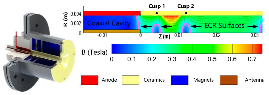
3.3. The Microwave Discharge Cusped Field Thruster

Significant negative size-effect has been confirmed during downscaling, including performance degradation and operation range limitation [73]. Our previous works show that the size effect is a bottleneck problem that is hard to solve by component geometry and configuration optimization. The ionization is inefficient due to limited space and an enlarged surface-to-volume ratio in a miniaturized cusped field thruster. These facts mean that external methods are necessary to improve the low mass flow rate performance in a μN-level cusped field thruster. In respect to a μN-level cusped field thruster, a non-uniform magnetic field is produced in a narrow room, and electron cyclotron resonance (ECR) is considered a competent tool for discharge enhancement [74]. After this, a microwave discharge cusped field thruster was released which satisfied the requirements of gravitational wave detection missions.
ECR ion source is an effective low-pressure microwave plasma generator with exceptional stability and repeatability [75]. The first-generation microwave discharge cusped field thruster was designed with a cylindrical antenna located in the near-anode region. Through this antenna, microwave radiation at 2.45 GHz is transmitted into the 6 mm-diameter thruster channel in TEM coaxial mode. Electrons are heated to a high temperature and inelastic collisions are induced. In a cusped field thruster, several ECR surfaces are formed near the magnetic cusps, as shown in Figure 19.
The microwave discharge cusped field thruster is able to ignite by both the DC power supply and microwave (MW) power supply. Three operating modes are achieved: ECR&CFT combined mode with both DC and MW on, CFT mode with only DC on, and ECR mode with only MW on, as shown in Figure 20.
The ECR mode performs a single peak plume with relatively low ion energy from 12 eV to 18 eV, and ions accelerate in the exit magnetic nozzle. Low ion energy makes the ECR mode not effective in generating considerable thrust. In contrast, experimental results show that the combined mode shows similar ion energy to the CFT mode. Significant ionization enhancement is found in the combined mode. With the introduction of microwaves, propellant utilization and thrust are raised several times higher in low mass flow rate conditions, but this improvement tends to decrease remarkably as the mass flow rate increases, as Figure 21 shows. This phenomenon is supposed to result from microwave reflection as the plasma density rises as the mass flow rate increases. When the plasma angular frequency ω p 17.96 π n e [ m 3 ] is higher than the microwave angular frequency, the microwave is reflected. The reflection lowers the microwave power feeding efficiency in high mass flow rate conditions.
Though the feasibility of microwave enhancement in a cusped field thruster is experimentally validated, the first-generation microwave discharge cusped field thruster operates with relatively low performance [76]. The cylindrical antenna takes up the position of the inner electron conduction route, which makes it hard to form a DC discharge. Besides, this configuration makes it hard to insulate the microwave-feeding structure from the anode. However, an improvement idea to make use of a coaxial transmission line resonator (CTLR) [77] was formulated to solve the problem.
The coaxial resonator consists of a coaxial resonant cavity where one end is short-circuited, and the other is open, as Figure 22 shows. The length of the cavity is an odd number of quarter wavelengths (λ/4 in this work). This configuration produces the largest electric field at the open end of the cavity when at resonance to ionize the neutral gas inside the channel. The plasma produced inside the channel is accelerated by the DC axial electric field generated between the anode and cathode. In order to minimize the thrust vector deflection caused by the traditional hollow cathode, a LaB6 thermionic emission cathode is adopted here, which provides approximately 10 mA of electron emission current. The MW coaxial resonant cusped field thruster can operate steadily in two modes: MW-excited mode (only MW source on) and MW–DC combined mode (both MW and DC on), as Figure 23 shows.
This configuration makes the microwave discharge cusped field thruster achieve a continuously adjustable thrust that ranges from 1.9 to 30.8 μN, with a specific impulse from 70.5 to 804.7 s (Figure 24). Compared with the low power cusped field thruster explored in previous work (27–868 μN thrust and 22–1208 s specific impulse), the minimum thrust is significantly lowered with a higher specific impulse at lower thrust conditions. Another remarkable result is that the thruster is able to work steadily with an extremely low mass flow rate of 0.04 sccm, which is unprecedentedly low for a cusped field thruster. However, this prototype does not perform with high total efficiency, while the thermionic emission cathode is a preliminary model as well [78]. Since the extremely low mass flow rate discharge is achieved, which is also found to operate with microwave power as low as 1 W, there could be room to make improvements. Optimization efforts on microwave feeding structure, magnetic topology, components materials and other configurations are still to be done in the future, hopefully to meet the gravitational wave detection mission requirements.

4. Conclusions

The cusped field thruster is a candidate microthruster for the gravitational wave detection mission with advantages of low complexity, potential long life and large throttling ability on thrust. Besides the GW mission, the cusped field thruster also shows competitiveness for small satellite missions and space science missions demanding a drag-free system. This paper presents a brief review of the research on cusped field thrusters at Harbin Institute of Technology since 2012, including efforts on low power prototype iterations, structure configuration optimization, physical mechanism study, thruster downscaling and preliminary investigation of the microwave discharge cusped field thruster.
Prototypes on thrust level from 100 mN to 7 mN are experimentally investigated, and the general large throttling ability is verified. A series of experiments and simulations are carried out to study the operation mechanism, the component effects and the optimization methods of the cusped field thruster. Results show that:
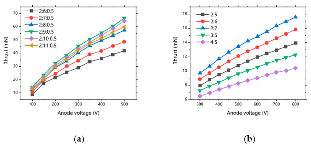
  • A higher downstream magnet ratio leads to flatter exit magnetic separatrix and extension of the ionization region, and, as a result, more focused plume and better performance.
  • A higher magnetic field intensity gives rise to more effective confinement of electrons, and a reduction of propellent utilization due to ionization region narrowness.
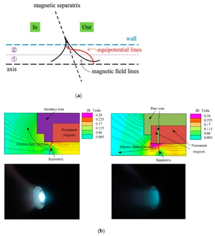
  • The main potential drop locates near the channel exit in a cusped field thruster, which makes the exit magnetic separatrix a determinant factor of plume divergence. Thus, plume divergence reduction is achieved through optimization on it.
  • The variable cross-section is applied to change the mass flow flux distribution in the channel, and a spacer with appropriate location contributes to better total performance by enhancing the ionization in the dominant region.
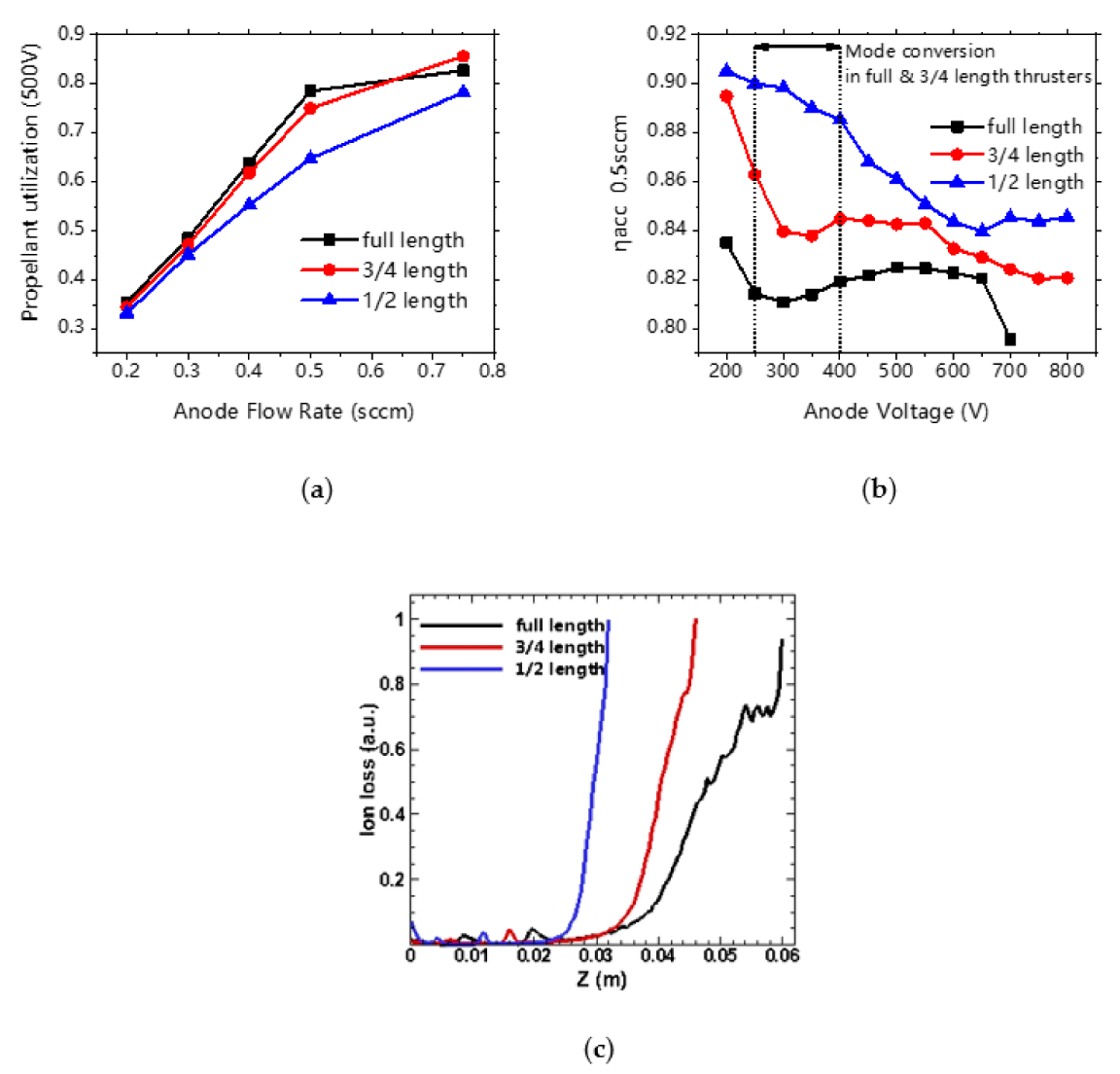
  • Two electron conduction routes are found in the cusped field thruster. The competition between the two electron routes, as well as the two ionization regions, is the intrinsic reason for the mode transition phenomenon.
Cusped field thruster downscaling works are carried out, including investigations on thruster geometry, expanding cross-section configuration and channel wall materials. Results show that:
  • Size effects are significant in cusped field thrusters, but diameter reduction is still necessary for downscaling because of the significant mass flow flux difference.
  • An equilibrium on energy efficiency and propellant utilization should be considered to find out the optimal channel length for a cusped field thruster.
  • The equilibrium on electron temperature and electron loss should also be considered to find out the wall material with an appropriate SEE coefficient.
  • Expanding cross-section configuration contributes to a wider operation range and better mode stability.
  • The DC discharge cusped field thruster is unlikely to meet the ultimate requirements of GW detection mission.
A novel concept of the microwave discharge cusped field thruster is carried out and experimentally investigated. ECR is successfully induced in a low power cusped field thruster, and the ionization enhancement is verified on low mass flow rate conditions. Using a coaxial transmission line resonator (CTLR), the second-generation microwave discharge cusped field thruster performs a 1.9 to 30.8 μN thrust with an extremely low mass flow rate of 0.04 sccm. Further studies and efforts for optimization of the thruster is to be done in future works.

Author Contributions

Conceptualization, H.L. and M.Z.; validation, H.L., M.Z., X.N., H.H. and D.Y.; formal analysis, M.Z.; writing—original draft preparation, M.Z.; writing—review and editing, M.Z.; visualization, M.Z.; supervision, H.H. and D.Y.; project administration, H.L. and D.Y.; funding acquisition, H.L. All authors have read and agreed to the published version of the manuscript.

Funding

This research was funded by the National Natural Science Foundation of China, grant number 51776047.

Conflicts of Interest

The authors declare no conflict of interest.

References

  1. Kwee, P.; Bogan, C.; Danzmann, K.; Frede, M.; Kim, H.; King, P.; Pöld, J.; Puncken, O.; Savage, R.L.; Seifert, F.; et al. Stabilized high-power laser system for the gravitational wave detector advanced LIGO. Opt. Express 2012, 20, 10617–10634. [Google Scholar] [CrossRef] [PubMed] [Green Version]
  2. Debra, D.B.; Conklin, J.W. Measurement of drag and its cancellation. Class. Quantum Gravity 2011, 28. [Google Scholar] [CrossRef]
  3. De Rosa, R.; Di Fiore, L.; Garufi, F.; Grado, A.; La Rana, A.; Milano, L. An optical readout system for the drag free control of the LISA spacecraft. Astropart. Phys. 2011, 34, 394–400. [Google Scholar] [CrossRef] [Green Version]
  4. Acernese, F.; De Rosa, R.; Giordano, G.; Romano, R.; Vilasi, S.; Barone, F. Low frequency—High sensitivity horizontal inertial sensor based on folded pendulum. J. Phys. Conf. Ser. 2012, 363. [Google Scholar] [CrossRef]
  5. Cui, K.; Liu, H.; Jiang, W.; Yu, D. Effects of Thrust Noise and Measurement Noise on Drag-Free and Attitude Control System. Microgravity Sci. Technol. 2020, 32, 189–202. [Google Scholar] [CrossRef]
  6. Cui, K.; Liu, H.; Jiang, W.J.; Sun, Q.Q.; Hu, P.; Yu, D.R. Effects of cusped field thruster on the performance of drag-free control system. Acta Astronaut. 2018, 144, 193–200. [Google Scholar] [CrossRef]
  7. Hild, S.; Abernathy, M.; Acernese, F.; Amaro-Seoane, P.; Andersson, N.; Arun, K.; Barone, F.; Barr, B.; Barsuglia, M.; Beker, M.; et al. Sensitivity studies for third-generation gravitational wave observatories. Class. Quantum Gravity 2011, 28. [Google Scholar] [CrossRef]
  8. Ziemer, J.K.; Merkowitz, S.M. Microthrust propulsion for the LISA mission. In Proceedings of the 40th AIAA/ASME/SAE/ASEE Joint Propulsion Conference and Exhibit, Fort Lauderdale, FL, USA, 11–14 July 2004; pp. 1–9. [Google Scholar] [CrossRef] [Green Version]
  9. Baker, J.; Barausse, E.; Bender, P.; Bortoluzzi, D.; Camp, J. Laser Interferometer Space Antenna (LISA). Van Nostrand’s Sci. Encycl. 2007. [Google Scholar] [CrossRef]
  10. LISA Simulation Working Group. LISA Science Study Team LISA Science Requirements Document; European Space Researchand Technology Centre: Noordwijk, The Netherlands, 2018; pp. 1–46. [Google Scholar]
  11. Mueller, J. Thruster options for microspacecraft: A review and evaluation of existing hardware and emerging technologies. In Proceedings of the 33rd Joint Propulsion Conference and Exhibit, Seattle, WA, USA, 6–9 July 1997. [Google Scholar] [CrossRef]
  12. Huberman, M.N.; Beynon, J.C.; Cohen, E.; Goldin, D.S.; Kidd, P.W.; Zafran, S. Present status of colloid microthruster technology. J. Spacecr. Rocket. 1968, 5, 1319–1324. [Google Scholar] [CrossRef]
  13. Ciaralli, S.; Coletti, M.; Gabriel, S.B. Performance and lifetime testing of a pulsed plasma thruster for Cubesat applications. Aerosp. Sci. Technol. 2015, 47, 291–298. [Google Scholar] [CrossRef]
  14. Lange, B. The drag-free satellite. AIAA J. 1964, 2, 1590–1606. [Google Scholar] [CrossRef]
  15. Folkner, W.M.; Bender, P.L.; Stebbins, R.T. LISA Mission Concept Study; Jet Propulsion Laboratory: Pasadena, CA, USA, 1998. [Google Scholar]
  16. Luo, J.; Chen, L.; Duan, H.; Gong, Y. TianQin: A space-borne gravitational wave detector. Class. Quantum Gravity 2016, 33, 035010. [Google Scholar] [CrossRef] [Green Version]
  17. Luo, Z.; Guo, Z.K.; Jin, G.; Wu, Y.; Hu, W. A brief analysis to Taiji: Science and technology. Results Phys. 2020, 16, 1–8. [Google Scholar] [CrossRef]
  18. Armano, M.; Audley, H.; Baird, J.; Binetruy, P.; Born, M.; Bortoluzzi, D.; Castelli, E.; Cavalleri, A.; Cesarini, A.; Cruise, A.M.; et al. LISA Pathfinder micronewton cold gas thrusters: In-flight characterization. Phys. Rev. D 2019, 99, 122003. [Google Scholar] [CrossRef] [Green Version]
  19. Ziemer, J.K.; Randolph, T.M.; Franklin, G.W.; Hruby, V.; Spence, D.; Demmons, N.; Roy, T.; Ehrbar, E.; Zwahlen, J.; Martin, R.; et al. Colloid micro-newton thrusters for the space technology 7 mission. IEEE Aerosp. Conf. Proc. 2010. [Google Scholar] [CrossRef]
  20. Armano, M.; Benedetti, M.; Bogenstahl, J.; Bortoluzzi, D.; Bosetti, P.; Brandt, N.; Cavalleri, A.; Ciani, G.; Cristofolini, I.; Cruise, A.M.; et al. LISA Pathfinder: The experiment and the route to LISA. Class. Quantum Gravity 2009, 26. [Google Scholar] [CrossRef]
  21. Armano, M.; Audley, H.; Baird, J.; Binetruy, P.; Born, M.; Bortoluzzi, D.; Castelli, E.; Cavalleri, A.; Cesarini, A.; Cruise, A.M.; et al. LISA Pathfinder platform stability and drag-free performance. Phys. Rev. D 2019, 99, 082001. [Google Scholar] [CrossRef] [Green Version]
  22. Ziemer, J.; Gamero-Castaño, M.; Hruby, V.; Spence, D.; Demmons, N.; McCormick, R.; Roy, T.; Gasdaska, C.; Young, J.; Connolly, B. Colloid Micro-Newton Thruster Development for the ST7-DRS and LISA Missions. In Proceedings of the 41st AIAA/ASME/SAE/ASEE Joint Propulsion Conference & Exhibit, Tucson, AZ, USA, 10–13 July 2005; pp. 1–9. [Google Scholar] [CrossRef] [Green Version]
  23. Abgaryan, V.K.; Kruglov, K.I. Thermal model of RF ion thrusters and ion sources. J. Surf. Investig. 2015, 9, 1137–1143. [Google Scholar] [CrossRef]
  24. Hey, F.G. Micro Newton Thruster Development; Springer: Wiesbaden, Germany, 2018; ISBN 9783658212087. [Google Scholar]
  25. Danzmann, K. Laser Interferometer Space Antenna—A Proposal in Response to the ESA Call for L3 Mission Concepts; European Space Agency: Paris, France, 2017; pp. 1–41. [Google Scholar]
  26. Brandt, T.; Kiel, C.; Trottenberg, T.; Groll, R.; Jansen, F.; Kersten, H.; Braxmaier, C. Simulation of a down-scaled HEMP-Thruster. In Proceedings of the 5th German-Russian Conference on Electric Propulsion and Their Application, Dresden, Deutschland, 7–12 September 2015. [Google Scholar]
  27. Kornfeld, G.; Harmann, H.-P.; Koch, N. Status and Limited Life Test Results of the Cylindrical HEMP 3050 Thruster. In Proceedings of the 41st AIAA/ASME/SAE/ASEE Joint Propulsion Conference & Exhibit, Tucson, Arizona, 10–13 July 2005. [Google Scholar] [CrossRef]
  28. Kornfeld, G.; Koch, N.; Harmann, H.P. Physics and Evolution of HEMP-Thrusters. In Proceedings of the 30th International Electric Propulsion Conference, Florence, Italy, 17–20 September 2007. [Google Scholar]
  29. Matyash, K.; Schneider, R.; Mutzke, A.; Kalentev, O.; Taccogna, F.; Koch, N.; Schirra, M. Kinetic simulations of SPT and HEMP thrusters including the near-field plume region. IEEE Trans. Plasma Sci. 2010, 38, 2274–2280. [Google Scholar] [CrossRef] [Green Version]
  30. Kornfeld, G.; Koch, N.; Coustou, G. First Test Results of the Hemp Thruster Concept. In Proceedings of the 28th International Electric Propulsion Conference, Toulouse, France, 17–21 March 2003; pp. 1–10. [Google Scholar]
  31. Yongjie, D.; Hong, L.; Liqiu, W.; Yanlin, H.; Yan, S.; Hui, L.; Zhongxi, N.; Wei, M.; Daren, Y. Overview of Hall Electric Propulsion in China. IEEE Trans. Plasma Sci. 2018, 46, 263–282. [Google Scholar] [CrossRef]
  32. Koch, N. Der HEMP Thruster—Vorstellung Eines Neuartigen, Höchst Leistungsfähigen Elektrischen Triebwerks Für Satelliten und Interplanetare Sonden. 2003, pp. 1–34. Available online: https://www.dlr.de/rd/Portaldata/28/Resources/dokumente/RK/kornfeld-hemp_thruster.pdf (accessed on 21 May 2021).
  33. Koch, N.; Harmann, H.-P.; Kornfeld, G. First Test Results of the 1 to 15 kW Coaxial HEMP 30250 Thruster. In Proceedings of the 41st AIAA/ASME/SAE/ASEE Joint Propulsion Conference & Exhibit, Tucson, Arizona, 10–13 July 2005; pp. 1–5. [Google Scholar] [CrossRef]
  34. Genovese, A.; Lazurenko, A.; Koch, N.; Weis, S.; Schirra, M.; van Reijen, B.; Haderspeck, J.; Holtmann, P. Endurance Testing of HEMPT-based Ion Propulsion Modules for SmallGEO. In Proceedings of the 32nd International Electric Propulsion Conference, Wiesbaden, Germany, 1–15 September 2011; pp. 1–9. [Google Scholar]
  35. Kornfeld, G.; Koch, N.; Harmann, H.-P.; Micheli, P.; Meusemann, H.; Gengembre, E. High Power HEMP-Thruster Module, Status and Results of a DLR and ESA Development Program. In Proceedings of the 42nd AIAA/ASME/SAE/ASEE Joint Propulsion Conference & Exhibit, Sacramento, CA, USA, 9–12 July 2006; pp. 1–9. [Google Scholar] [CrossRef]
  36. Gildea, S.R.; Batishchev, O.; Martínez-Sánchez, M. Fully kinetic modeling of divergent cusped-field thrusters. In Proceedings of the 45th AIAA/ASME/SAE/ASEE Joint Propulsion Conference & Exhibit, Denver, CO, USA, 2–5 August 2009. [Google Scholar] [CrossRef]
  37. Courtney, D.G.; Lozano, P.; Martínez-Sánchez, M. Continued investigation of diverging cusped field thruster. In Proceedings of the 44th AIAA/ASME/SAE/ASEE Joint Propulsion Conference & Exhibit, Hartford, CT, USA, 21–23 July 2008. [Google Scholar] [CrossRef]
  38. Gildea, S.R.; Matlock, T.S.; Martínez-Sánchez, M.; Hargus, W.A. Erosion measurements in a low-power cusped-field plasma thruster. J. Propuls. Power 2013, 29, 906–918. [Google Scholar] [CrossRef] [Green Version]
  39. MacDonald, N.A.; Young, C.V.; Cappelli, M.A.; Hargus, W.A. Ion velocity and plasma potential measurements of a cylindrical cusped field thruster. J. Appl. Phys. 2012, 111. [Google Scholar] [CrossRef] [Green Version]
  40. MacDonald, N.A.; Cappelli, M.A.; Gildea, S.R.; Martínez-Sánchez, M.; Hargus, W.A. Laser-induced fluorescence velocity measurements of a diverging cusped-field thruster. J. Phys. D. Appl. Phys. 2011, 44. [Google Scholar] [CrossRef]
  41. Macdonald, N.A.; Cappelli, M.A.; Hargus, W.A. Time-synchronized continuous wave laser-induced fluorescence axial velocity measurements in a diverging cusped field thruster. J. Phys. D. Appl. Phys. 2014, 47. [Google Scholar] [CrossRef]
  42. Sun, G.; Yu, D.; Chen, P. Research of a Cusped Field Thruster Using Different Wall Materials. 2015. Available online: https://xueshu.baidu.com/usercenter/paper/show?paperid=cb43c6a047bd9c8ce31e86a82c56534d (accessed on 21 May 2021).
  43. Cui, K.; Liu, H.; Jiang, W.; Yu, D. Thrust noise cause analysis and suppression of a cusped field thruster. Acta Astronaut. 2021, 179, 322–329. [Google Scholar] [CrossRef]
  44. Canuto, E.; Molano, A.; Massotti, L. Drag-free control of the GOCE satellite: Noise and observer design. IEEE Trans. Control Syst. Technol. 2010, 18, 501–509. [Google Scholar] [CrossRef] [Green Version]
  45. Ma, C.; Liu, H.; Hu, Y.; Yu, D.; Chen, P.; Sun, G.; Zhao, Y. Experimental study on a variable magnet length cusped field thruster. Vacuum 2015, 115, 101–107. [Google Scholar] [CrossRef]
  46. Liu, H.; Chen, P.B.; Sun, Q.Q.; Hu, P.; Meng, Y.C.; Mao, W.; Yu, D.R. Design of a cusped field thruster for drag-free flight. Acta Astronaut. 2016, 126, 35–39. [Google Scholar] [CrossRef]
  47. Revell, K.D. City Planning, State-Building, and the Changing Scope of the Police Power; Cambridge University Press: Cambridge, UK, 2016; Volume 13, pp. 50–145. [Google Scholar]
  48. Canuto, E.; Bona, B.; Calafiore, G.; Indri, M. Drag free control for the European satellite GOCE. Part I: Modelling. Proc. IEEE Conf. Decis. Control 2002, 2, 1269–1274. [Google Scholar] [CrossRef]
  49. Keller, A. Feasibility of a Down-Scaled HEMP Thruster. Ph.D. Thesis, Justus-Liebig-University Gießen, Gießen, Germany, 2013. [Google Scholar]
  50. Braxmaier, C.; Tajmar, M.; Sell, A.; Eckert, K.; Weise, D.; Saks, N.; Johann, U. HEMPT Downscaling, Way Forward to the First EM for CubeSat Applications. In Proceedings of the the 35th International Electric Propulsion Conference, Atlanta, GA, USA, 8–12 October 2017; pp. 1–9. [Google Scholar]
  51. Keller, A. Feasibility of a down-scaled HEMP-Thruster. IEPC-2011-138. In Proceedings of the 32nd International Electric Propulsion Conference, Wiesbaden, Germany, 11–15 September 2011; pp. 1–6. [Google Scholar]
  52. Brandt, T.; Braxmaier, C.; Jansen, F.; Trottenberg, T.; Kersten, H.; Hey, F.G.; Johann, U.; Groll, R. Simulation for an improvement of a down-scaled HEMP thruster. In Proceedings of the 34th International Electric Propulsion Conference, Kobe, Japan, 7–10 July 2015; pp. 6–10. [Google Scholar]
  53. Liu, H.; Sun, G.; Zhao, Y.; Chen, P.; Ma, C.; Wu, H.; Yu, D. Plume control of a cusped field thruster. IEEE Trans. Plasma Sci. 2015, 43, 127–129. [Google Scholar] [CrossRef]
  54. Hu, P.; Liu, H.; Gao, Y.; Mao, W.; Yu, D. An experimental study of the effect of magnet length on the performance of a multi-cusped field thruster. J. Phys. D. Appl. Phys. 2016, 49. [Google Scholar] [CrossRef]
  55. Zhao, Y.; Liu, H.; Yu, D.; Ma, C. Particle-in-Cell Simulations for a variable magnet length Cusped-Field thruster. IEPC-2013-171. In Proceedings of the 33rd International Electric Propulsion Conference, Washington, DC, USA, 6–10 October 2013; pp. 1–5. [Google Scholar]
  56. Hu, P.; Liu, H.; Gao, Y.; Yu, D. Effects of magnetic field strength in the discharge channel on the performance of a multi-cusped field thruster. AIP Adv. 2016, 6. [Google Scholar] [CrossRef]
  57. Zhao, Y.J.; Liu, H.; Yu, D.R.; Hu, P.; Wu, H. Particle-in-cell simulations for the effect of magnetic field strength on a cusped field thruster. J. Phys. D. Appl. Phys. 2014, 47. [Google Scholar] [CrossRef]
  58. Hey, F.G.; Brandt, T.; Kornfeld, G.; Braxmaier, C.; Tajmar, M.; Johann, U. Downscaling a HEMPT to micro-Newton Thrust levels: Current status and latest results. In Proceedings of the 34th International Electric Propulsion Conference, Hyogo-Kobe, Japan, 4–10 July 2015; pp. 4–8. [Google Scholar]
  59. Fisch, N.J.; Raitses, Y.; Fruchtman, A. Ion acceleration in supersonically rotating magnetized-electron plasma. Plasma Phys. Control. Fusion 2011, 53. [Google Scholar] [CrossRef]
  60. Liu, H.; Chen, P.; Mao, W.; Yu, D.; Wang, C. Effect of the variable cross-section channel on performance of a cusped field thruster at low power. J. Phys. D. Appl. Phys. 2015, 48, 1–8. [Google Scholar] [CrossRef]
  61. Brandt, T.; Trottenberg, T.; Groll, R.; Jansen, F.; Hey, F.G.; Johann, U.; Kersten, H.; Braxmaier, C. Simulations on the influence of the spatial distribution of source electrons on the plasma in a cusped-field thruster. Eur. Phys. J. D 2015, 69. [Google Scholar] [CrossRef]
  62. Hu, P.; Mao, W.; Hu, Y.; Wu, P.; Shen, Y. Experimental study on two kinds of electron conduction routes in a multi-cusped field thruster. Plasma Res. Express 2019, 1, 025006. [Google Scholar] [CrossRef]
  63. Hu, P.; Liu, H.; Gao, Y.; Yu, D. Study on the structure and transition of the hollow plume in a multi-cusped field thruster. Phys. Plasmas 2016, 23. [Google Scholar] [CrossRef]
  64. Yu, D.; Hu, P.; Liu, H.; Shen, Y. Experimental study on the ionization regions in a multi-cusped field thruster. Plasma Sources Sci. Technol. 2018, 27. [Google Scholar] [CrossRef]
  65. Luo, J.; Bai, Y.Z.; Cai, L.; Cao, B.; Chen, W.M.; Chen, Y.; Cheng, D.C.; Ding, Y.W.; Duan, H.Z.; Gou, X.; et al. The first round result from the TianQin-1 satellite. Class. Quantum Gravity 2020, 37, 185013. [Google Scholar] [CrossRef]
  66. Conversano, R.W.; Goebel, D.M.; Hofer, R.R.; Mikellides, I.G.; Wirz, R.E. Performance analysis of a low-power magnetically shielded hall thruster: Experiments. J. Propuls. Power 2017, 33, 975–983. [Google Scholar] [CrossRef]
  67. Randolph, T.M.; von Jaskowsky, W.F.; Kelly, A.J.; Jahn, R.G. Measurement of ionization levels in the interelectrode region of an MPD thruster. In Proceedings of the AIAA/ASME/SAE/ASEE 28th Joint Propulsion Conference and Exhibit, Nashville, TN, USA, 6–8 July 1992. [Google Scholar] [CrossRef]
  68. Liu, H.; Zeng, M.; Yu, D.; Huang, H. Study of channel length effect on low power HEMP Thruster. Vacuum 2019, 163, 328–337. [Google Scholar] [CrossRef]
  69. Tondu, T.; Belhaj, M.; Inguimbert, V. Electron-emission yield under electron impact of ceramics used as channel materials in Hall-effect thrusters. J. Appl. Phys. 2011, 110, 1–5. [Google Scholar] [CrossRef]
  70. Raitses, Y.; Smirnov, A.; Staack, D.; Fisch, N.J. Measurements of secondary electron emission effects in the Hall thruster discharge. Phys. Plasmas 2006, 13, 1–4. [Google Scholar] [CrossRef] [Green Version]
  71. Zeng, M.; Liu, H.; Qiao, L.; Wang, F.; Huang, H.; Yu, D. Experimental investigation of dielectric wall material effects on low-power HEMP thruster. AIP Adv. 2020, 10. [Google Scholar] [CrossRef]
  72. Liu, H.; Zeng, M.; Jiang, W.; Yang, C.; Ning, Z.; Yu, D. Experimental investigation of the effects of variable expanding channel on the performance of a low-power cusped field thruster. AIP Adv. 2018, 8, 1–11. [Google Scholar] [CrossRef] [Green Version]
  73. Keller, A.; Köhler, P.; Hey, F.G.; Berger, M.; Braxmaier, C.; Feili, D.; Weise, D.; Johann, U. Parametric study of HEMP-thruster downscaling to μn thrust levels. IEEE Trans. Plasma Sci. 2015, 43, 45–53. [Google Scholar] [CrossRef]
  74. Ganguli, A.; Tarey, R.D.; Narayanan, R.; Verma, A. Evaluation of compact ECR plasma source for thruster applications. Plasma Sources Sci. Technol. 2019, 28. [Google Scholar] [CrossRef]
  75. Lebedev, Y.A. Microwave discharges at low pressures and peculiarities of the processes in strongly non-uniform plasma. Plasma Sources Sci. Technol. 2015, 24. [Google Scholar] [CrossRef]
  76. Liu, H.; Zeng, M.; Chen, Z.; Qiao, L.; Huang, H.; Yu, D. Electron cyclotron resonance discharge enhancement in a cusped field thruster. Plasma Sources Sci. Technol. 2020. [Google Scholar] [CrossRef]
  77. Choi, J.; Iza, F.; Do, H.J.; Lee, J.K.; Cho, M.H. Microwave-excited atmospheric-pressure microplasmas based on a coaxial transmission line resonator. Plasma Sources Sci. Technol. 2009, 18. [Google Scholar] [CrossRef]
  78. Kottke, N.G.; Vaupel, M.; Tajmar, M.; Konrad, W.; Saks, N.; Hey, F.G. Comparison of the thermionic emission properties of LaB6 and C12A7. In Proceedings of the 36th International Electric Propulsion Conference, Vienna, Austria, 15–20 September 2019; pp. 1–10. [Google Scholar]
Figure 1. Drag-free control system.
Applsci 11 06549 g001
Figure 2. (a) Cold gas thruster, (b) colloid thruster, (c) radio frequency ion thruster and (d) cusped field thruster.
Applsci 11 06549 g002
Figure 3. Schematic view of the cusped field thruster concept.
Applsci 11 06549 g003
Figure 4. HEMPT prototypes from Thales.
Applsci 11 06549 g004
Figure 5. (a) DCFT of MIT and (b) CCFT of Stanford.
Applsci 11 06549 g005
Figure 6. Thrusters of (a) 20–110 mN level, (b) 10–60 mN level, (c) 1–20 mN level and (d) 0.5–7 mN level at HIT.
Applsci 11 06549 g006
Figure 7. Micro-newton cusped field thruster developed by Airbus.
Applsci 11 06549 g007
Figure 8. Experimental investigation results (thrust) of different (a) magnet length and (b) ratio.
Applsci 11 06549 g008
Figure 9. (a) Experimental results and (b) simulated electron density distribution of magnetic field strength effect in a cusped field thruster. In (a) F54–66 is the outer diameter (mm) of the magnets. In (b) the electron density distribution is plotted in /m3.
Applsci 11 06549 g009
Figure 10. Last magnetic separatrix effects on plume divergence. A demonstration of the relationship between magnetic separatrix and equipotential lines (a) and an optimization on last magnet separatrix (b).
Applsci 11 06549 g010
Figure 11. Variable cross-section effects of the cusped field thruster. (a) Spacer configuration and (b) thrust difference with different spacer locations.
Applsci 11 06549 g011
Figure 12. Experimental results of the two conduction routes in the cusped field thruster.
Applsci 11 06549 g012
Figure 13. Simulation and experimental results of the two ionization regions characteristics.
Applsci 11 06549 g013
Figure 14. Ignition anode voltages of thrusters with different channel diameters (24 mm, 12 mm and 6 mm) and the same channel length (60 mm).
Applsci 11 06549 g014
Figure 15. Thrust and specific operation spaces of thrusters with different diameters. (a,b) 6 mm, (c,d) 12 mm and (e,f) 24 mm.
Applsci 11 06549 g015
Figure 16. Differences among thrusters with different channel lengths: (a) propellant consumption and (b) ion acceleration efficiency. In (c), the results of the simulation of ion loss on channel walls for different channel lengths are presented.
Applsci 11 06549 g016
Figure 17. Performance difference of thrusters with different expanding angle configurations; (a) Operation space, (b) ion current density distribution and (c) thrust. CFTK0, 4 and 8 are cusped field thrusters with different channel expanding angles (0°, 4° and 8°, respectively).
Applsci 11 06549 g017
Figure 18. (a) The μN-level cusped field thruster in HIT, and its performance on (b) thrust operation range and (c) thrust noise PSD.
Applsci 11 06549 g018
Figure 19. First-generation microwave discharge cusped field thruster, with several ECR surfaces marked out.
Applsci 11 06549 g019
Figure 20. Three operating modes of the microwave discharge cusped field thruster.
Applsci 11 06549 g020
Figure 21. (a) Thrust curves of the three modes in a microwave discharge cusped field thruster. (b) Thrust difference, propellant utilization difference, and energy efficiency difference between combined mode and CFT mode.
Applsci 11 06549 g021
Figure 22. Schematic cutaway view of the MW coaxial resonant cusped field thruster and its operational schematic diagram.
Applsci 11 06549 g022
Figure 23. Microwave discharge mode and combined discharge mode of the MW coaxial resonant cusped field thruster.
Applsci 11 06549 g023
Figure 24. Thrust variation with anode voltage and mass flow rate (a), and thrust variation with micro-wave power and mass flow rate (b) in a MW coaxial resonant cusped field thruster.
Applsci 11 06549 g024
Table 1. Four candidate thruster types and their technology readiness levels given by LISA.
Thruster TypeTechnology Readiness Levels
Cold gas thruster9
Colloid thruster7 (head), 5 (feed system)
Radio frequency ion thruster4
Cusped field thruster3
Table 2. Performance of HEMPT3050 series.
YearPrototypeAnode Voltage (V)Mass Flow Rate (sccm)Thrust (mN)Specific Impulse (s)Total Efficiency (%)
2002DM3a-MS2200~60085~10500~120013~20
2003DM6 MS1600~12002030~451700~250027~35
2004DM7600~12002036~582000~300035~44
2004DM8600~12002033~57-36~47
2005DM9-2600~12002050~702500~300040~50
2005DM9-1800~10002015~702500~300036~46
Table 3. Performance of cusped field thruster prototypes in HIT.
YearPrototypeAnode Voltage (V)Mass Flow Rate (sccm)Thrust (mN)Specific Impulse (s)Total Efficiency (%)
2012CFT [45]100~50020–5020–110500~230010–35
2014CFT100–50010–3010–50500–22006–35
2015CFT [46]300~10003–111–20120~18005–30
2016CFT600~12001–30.5–7400–25007–22
Publisher’s Note: MDPI stays neutral with regard to jurisdictional claims in published maps and institutional affiliations.

