Abstract
The impacts of climate change on unsaturated porous media have been investigated through the coupled thermo-hydro-mechanical analysis by leveraging a discrete fracture model. The transport of gas and liquid phases in unsaturated porous media is captured under non-isothermal conditions. The balance principles of moisture energy and mass are associated with crack propagation. The temperature-dependent degree of saturation and permeability of water are incorporated into fracture based on the cubic law. Numerical examples are designed to evaluate the applicability of the proposed model against climate change. First, a double-notch plate domain is used to identify the sensitivity of various material properties on crack propagation associated with mechanical loading. Then, a masonry wall of drying under thermal action is studied to investigate its degradation by mimicking climatic load conditions. The results of numerical tests demonstrate the capabilities of the proposed model for practical application well.
1. Introduction
The failures of many geotechnical structures are often triggered by the fracture of porous materials such as stiff clays and rocks, which generally consist of three different phases, including solid, water, and gas. Therefore, the damage and crack of those materials are closely related to the interactions among those constituents. Climate change and the associated natural disasters further complicate crack propagation in porous media because of the variably saturated and non-isothermal nature of the problem. Examples may include cracks in dams, slopes, and retaining walls under heavy rainfall or heatwave conditions along with mechanical loading. Due to this complexity, it is challenging to establish a coupled thermo-hydro-mechanical (THM) system and apply the model to analyze crack propagation for practical purposes.
Regarding coupled multi-physics analysis, including the THM analysis, there are different fracture mechanisms; for example, (1) tensile cracks are one of the most common fracture modes due to mechanical loading under tension; (2) thermal cracks are caused by the temperature difference in the body of the material accompanied by thermal contraction [1]; and (3) shrinkage cracks [2] are the result of the loss of moisture, in which the cracks are caused by changing internal equilibrium condition due to water pressure fluctuation combined with shrinkage and thermal stresses [3]. Since moisture and heat transfer often occur simultaneously and the state of stress is closely dependent on hydro and thermal actions, identifying the real cause of cracking is difficult and requires a profound understanding of thermo-hydro-mechanical processes in porous media.
There exist various approaches for modeling unsaturated porous media. The theoretical frameworks for coupled heat and moisture transfer in unsaturated porous media are well defined, both in deformable [4] and undeformable states [5]. Along with governing equations to describe the behavior of porous media, the non-isothermal effect is incorporated into soil–water retention curves [6], hydraulic conductivity [7], and thermal conductivity [8]. These models are implemented through research-oriented codes such as Theta-Stock [9], CODE-Bright [10], and CODE-ASTER [11]. However, most coupled multi-physics modeling tools have limitations considering cracks and damage in porous media.
The first innovative theory about fracture is the linear elastic fracture mechanics (LEFM). Although the linear elastic fracture mechanics (LEFM) has been well established [12], this approach has a critical limitation, that is, the size of crack and specimen should be large enough compared to that of the fracture process zone (FPZ) [13]. In addition, the LFEM is inappropriate to capture quasi-brittle fracture behavior for soils and rocks. The cohesive crack model was developed separately by [2,13], which is one of the simplest methods to treat the singularity issue of the stress at the crack tip. The traction-separation relationship across the crack faces regulates the stress field around the crack body during crack propagation. Later, the concept of fracture energy and several traction-separation relationships were proposed into the cohesive crack model [14].
Many methods, including zero-thickness interface element [12], the boundary element method [15], Meshless methods [16], the distinct element method [17], and the extended finite element method (XFEM) [18], were developed to couple the cohesive crack model within the continuum domain. The extended finite element method leverages the partition of unity concept to incorporate strong discontinuities in the context of the finite element method and resolves the remeshing issue of crack propagation. The XFEM includes enrichments to the continuous part of shape functions based on the analytical solution of the fracture problem.
The XFEM has been extended to capture crack propagation in porous media, which often requires investigating the fluid flow in deformable porous media associated with the physical process of fracture. For example, a two-scale model for the description of deformation and flow in saturated and unsaturated cracking porous media was presented ([19,20]). The mechanical interaction of crack and porous media using the cohesive crack model was simulated, and the coupled hydro-mechanical effect was analytically derived for fracture in porous media. This concept has been extended to incorporate the gas phase as an active phase in porous media [21]. A numerical model for the cohesive crack propagation in unsaturated porous media under a heat gradient effect was also proposed [22]. In this model, the following three zones were considered around the crack: two interfaces around the crack and the crack itself. The balance principles of mass and energy were derived for these zones to account for the crack and porous media interaction. The robustness of the model was presented using the degradation of the masonry structure. Recently, a new model that includes both moisture conservation and heat transfer in fractured porous media has been proposed [23].
In this study, the discrete thermo-hydro-mechanical model [23] is advanced to investigate the impact of climate change on fractured unsaturated porous media. In particular, the crack tracking algorithm is modified to correctly calculate the local discharge of moisture and heat along with each crack. The exchange of heat and moisture between the intact and cracked regions is considered to capture the coupled THM effects on a fracture smoothly. The discrete crack propagation is simulated via the extended finite element method (XFEM), where the suction in the pores induced by thermal and hydraulic actions is incorporated into the cohesive crack model. Numerical tests investigate the performance of the proposed model for climate change applications. Firstly, a double-notch unsaturated plate is designed to be stretched out, where the effects of parameters such as intrinsic permeability and initial crack length are investigated. Second, the desiccation of a masonry wall under climatic loading is designed: when the plaster layer on a brick wall dries, it shrinks and bends in the hole between the bricks. We found that the maximum tensile stress developed on the inner surface of the wall triggers crack initiation. As loading continues, the crack is found to bisect the plaster. This example further presents how the outside temperature and mass transfer coefficient affect the results.
The paper is organized as follows. In Section 2, the main aspects of the proposed model are explained briefly, including the conservation and the equilibrium equations, the interaction of crack and porous medium, and the spatial discretization of governing equations for implementation with temporal discretization. In Section 3, numerical examples that mimic climate loads in unsaturated porous media are presented with discussion, followed by the main conclusion in Section 4.
2. Governing Equations for Fractured Unsaturated Porous Media under the Non-Isothermal Condition
In this section, basic formulations of fractured porous media with varying saturations and temperatures are presented to revisit two basic theories for considering the thermo-hydraulic forces on the crack surface. The first theory [12] is about simultaneous heat and moisture movement in the porous body, adjusted to exchange heat and moisture between the intact body and the crack. The second theory is the cohesive crack model advanced to include the coupled thermo-hydraulic effect. Three sets of basic equations relative to two phases and temperature, plus the interaction of the crack and porous media, are briefly explained to complete the description. The fundamental concept of this model can be further found in [23].
2.1. Balance of Moisture
Moisture movement in multiphase porous media can be divided into two flows in liquid and vapor phases. The movement of moisture is under the influence of temperature and moisture content gradient and can be given as follows:
In Equation (1), the first, second, and third terms of the right-hand side indicate the moisture movement due to temperature gradient, moisture content gradient, and elevation difference. and denotes the thermal moisture diffusivity and isothermal moisture diffusivity. is the elevation difference and is the gravitational coefficient or the water permeability that takes effect from non-isothermal conditions of unsaturated porous media (Figure 1b) with the following form:
where and are the dynamic viscosity of water at the current temperature and reference temperature, respectively. is the relative permeability that reflects the fluid properties [23], and can be obtained as follows:
where is a reference permeability, is the material properties, and is the void ratio of porous matrix.

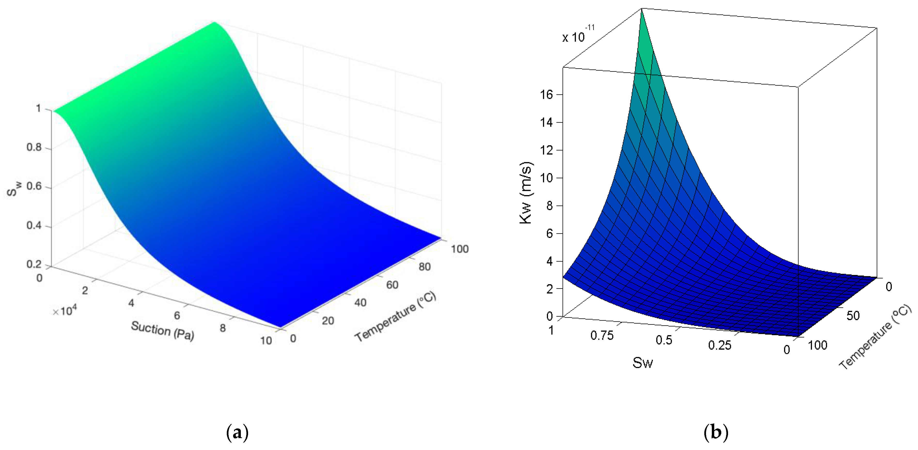
Figure 1.
State surfaces—(a) Degree of saturation, and (b) Water permeability with respect to temperature and suction.
Assuming phase change between liquid and water vapor, the continuity equation for the moisture phase of deformable porous media in non-isothermal condition could be given as follows:
where and are water and water vapor velocities, respectively; is the moisture content; is the solid phase porosity; and are water and vapor densities, respectively; and is the degree of saturation , where is the residual degree of saturation. One novelty of works of Gatmiri et al. ([6,24]) is the incorporation of the changes of saturation degree due to the thermal effects into the state surface of saturation degree based on experimental evidence. This state surface is shown in Figure 1a, and can be given as follows:
2.2. Balance of Energy
For the heat flow, the theory of Philip and de Vries [5] is used to model the total flow of latent and sensible heat in an unsaturated porous medium as follows:
Equation (6) consists of the following three distinctive parts: the first part is an indicator of conductive heat flow, the latent heat transfer due to the evaporation () is described by the second term, and the third part describes convective heat flow in liquid and water vapor phases. and denotes the water and vapor heat capacities, respectively. The energy conservation equation for unsaturated porous media considering non-isothermal conditions can be given as follows:
where is the heat flow and is the volumetric bulk heat content of the medium.
2.3. Balance of Linear Momentum
For the overall mixture, the equilibrium equation could be written as follows:
where is defined as total stress, is the body force vector, and is the average density of multiphase media that can be given as follows:
where is the solid phase density and is the volumetric moisture content.
The effective stress that governs the deformation of the solid skeleton for unsaturated porous media could be given as follows:
In Equation (10), is the effective stress vector; is the identity vector, which can be defined as ; and is the pore water pressure. The effect of temperature on deformation shows itself by the subtraction of thermal strain () from the total strain () in total stress vector expression, where is the thermal expansion coefficient; is the unknown temperature; and is the arbitrary reference temperature.
2.4. Crack-Porous Media Interaction Equations
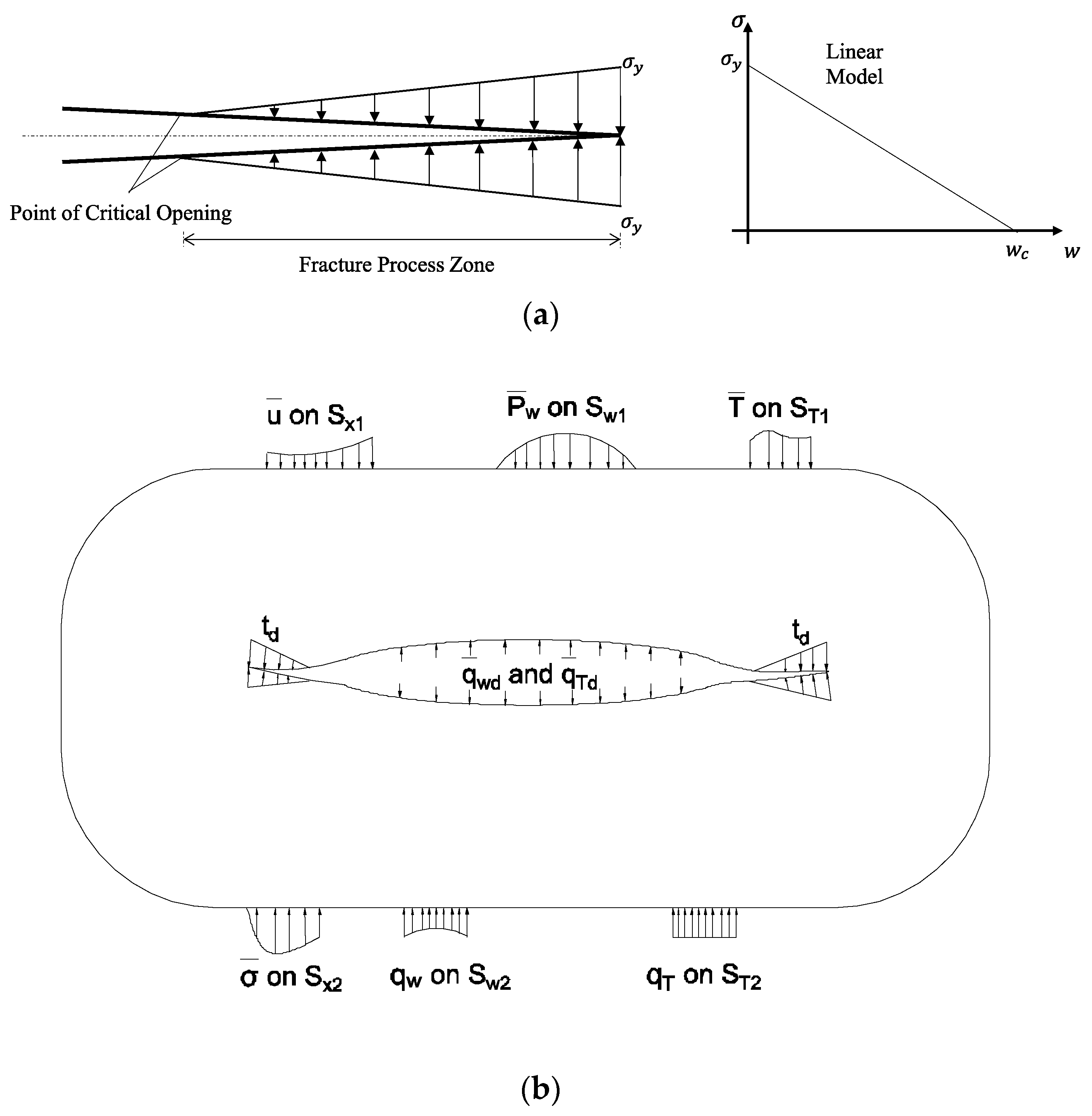
Since geological materials such as soil and rock do not exhibit the singularity of stress predicted by the linear elastic fracture mechanics (LEFM) at the crack tip, the cohesive crack model, which develops when the tip stress exceeds the tensile strength, could be a powerful alternative for the quasi-brittle materials. In addition to cohesive traction, the suction developed in the pores of the porous media acts on the crack faces as follows:
where is the modified crack opening due to the temperature difference between crack faces (, and is the dependant cohesive force, which is considered as a linear function of , as in Figure 2a. In this study, the linear function is adopted to reduce the complexity associated with cracking such that we focus more on the calculation of coupled suction and thermal impacts on porous media. Moreover, this treatment is aligned with the nature of cracks in fluid infiltrating porous media, which shows in-between the brittle and ductile fracture behaviors.

Figure 2.
(a) Schematics of crack-opening with traction-separation law, (b) Demonstration of the boundary condition on the crack and model surface.
As shown in Figure 2b, the crack in porous media leads to the exchange of moisture () and heat () between the crack and the porous media. These exchanged flows are calculated by rewriting the moisture mass and energy conservation equations around the crack as follows:
Here, the crack opening is expressed by 2, and and are the tangential and normal velocities of solid with respect to the crack. We note that and demonstrate the average and difference of variables at two opposite sides of the crack. The subscript defines the coefficients at the damaged area and there is a difference between damaged coefficients and continuum coefficients for the intrinsic permeability and porosity. The intrinsic permeability is defined using the cubic law, and the porosity is obtained as . We refer more details about other model parameters including , , , , and to [23].
2.5. Description of Strong Discontinuities and Solution Strategy
Spatial discretization is performed using the extended finite element method (XFEM) that enriches ordinary shape functions with additional terms for describing strong discontinuities. Temporal discretization is performed using the finite difference method. In the following parts of this section, each type of discretization is described briefly.
To begin with, spatial discretization should be performed to satisfy the physical condition of the proposed problem. For instance, the liquid phase should be entered into the crack, and the type of function for spatial discretization plays an important role in this action. These requirements include (1) the strong discontinuity of displacement field for fracture opening and (2) the weak discontinuity of water pressure and temperature fields for moisture and heat exchanges.
The strong discontinuity for crack opening means the displacement field and the gradient of displacement, strain, which has to be discontinuous between two faces of the fracture. The weak discontinuity of water pressure and temperature results in discontinuous water pressure gradients and temperature normal to the fracture. To have such fields, the classic finite element should be enriched to ensure that aforementioned assumptions are fulfilled. We note that only the nodes bisected by cracks are enriched. Since the fracture opening is zero around the crack tip and the moisture and heat flows are continuous, the nodes on the side where the crack tip lay on are not enriched.
In the XFEM, all the unknown variables are decomposed into standard and enriched parts. To model the desired discontinuity, the enrichment function is embedded in the enriched part. The extended finite element approximation for the displacement field can be given as follows:
where is the shape function and and are the standard and enriched degrees of displacement, respectively. and are the set of all the nodes and the enriched nodes in the domain. denotes the Heaviside function, taken into account for the consideration of the strong discontinuity of displacement field that can be given as follows:
where is the nearest projection of any point on the crack path. To obtain the value of the field variable on any enriched point, the Heaviside function is shifted by around any node. Similarly, the pressure and temperature unknowns are approximated as follows:
where and are standard shape functions for water pressure and temperature, respectively. and are standard degrees of freedom and and are enriched degrees of freedom for water pressure and temperature, respectively. In order to implement the weak discontinuity in the formulation, the distance function () is used.
The weak form of governing equations should also be discretized over time domain [24]. The single-step integration is applied to arbitrary variable with values and at times and
The coefficient specifies the type of interpolation: accounts for fully explicit, gives backward (fully implicit), defines linear interpolation (Cranck-Nicholson), and describes the Galerkin scheme.
3. Numerical Examples
The unsaturated porous media model described in the preceding section were developed as part of θ-STOCK, a powerful computational package for thermo-hydro-mechanical analysis of porous media [9]. In this section, two numerical problems are designed to show the robustness of the developed model associated with climate change. In the first example (Problem 1), the isothermal propagation of two cracks in an unsaturated porous plate is investigated. The effects of some factors such as porosity, intrinsic permeability, and initial crack length on crack propagation are examined, followed by a comparison with single crack propagation in that plate. In the second example (Problem 2), the more practical problem is simulated by considering crack propagation in a masonry wall due to drying shrinkage. Due to the climatic loadings and the difference between material properties, the plaster on the outer layer of a peripheral wall dries and bends in a hole created between the bricks. Lastly, a parametric study is carried out on the outside temperature and mass transfer coefficient to determine their effects on the obtained results.
3.1. Edge Discontinuities in Unsaturated Porous Media
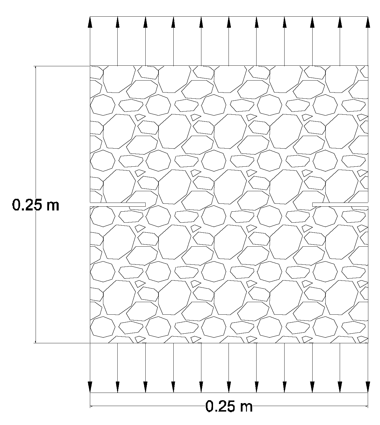
This problem is designed to investigate the isothermal behavior of an unsaturated porous plate for verification purposes of the proposed model. The problem is solved in a single edge crack by [20] and two discontinuities are considered in this study. A square plate in the plane strain conditions is given, where two existing cracks with an initial length of 0.05 m are aligned, as in Figure 3. The top and bottom surfaces of the domain are stretched out with the constant displacement rate of . All boundaries are assumed to be impermeable to the moisture.
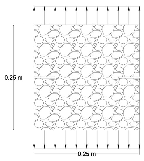
Figure 3.
Geometry and loading of Problem 1 (two existing cracks with the initial length of 0.05 m along the middle of a square domain).
In order to detect the presence of discontinuities via the XFEM, the level-set method is implemented. To define the geometry of each crack independently, three separate functions are required; one represents the crack body, and the other two show crack tips. For a large number of fractures, the calculation of Level Set functions for each crack requires high computational cost. To resolve this problem, the Level Set functions are only calculated for a narrow band of nodes around each crack [25]. Moreover, the leakage flux is calculated for each crack based on Equation (9), and then is added to general equilibrium equations. The material properties are presented in Table 1.

Table 1.
Material Properties of Problem 1.
Due to the geometrical symmetry of the problem, two tensile cracks are initiated and propagate toward each other along the horizontal direction. Since the stress significantly varies around the crack tip, the nonlocal stress may better capture the onset of crack propagation. For stress regularization around a specified radius in the neighborhood of the crack tip, the averaged stress values are calculated instead of the real crack tip stresses. When the value of this nonlocal stress exceeds the material’s cohesive strength, the crack starts to propagate. The length of the crack extension is determined based on the stress value at the Gauss points on the potential crack trajectory. If this stress on both Gauss points of an element surpasses the material’s tensile strength, the crack bisects that element. In this manner, it is possible that the crack can pass several elements in one step. The crack tip may exist inside an element. To satisfy the zero openings for crack tip displacement, however, it must be located on the edge of the element where the connected nodes are not enriched.
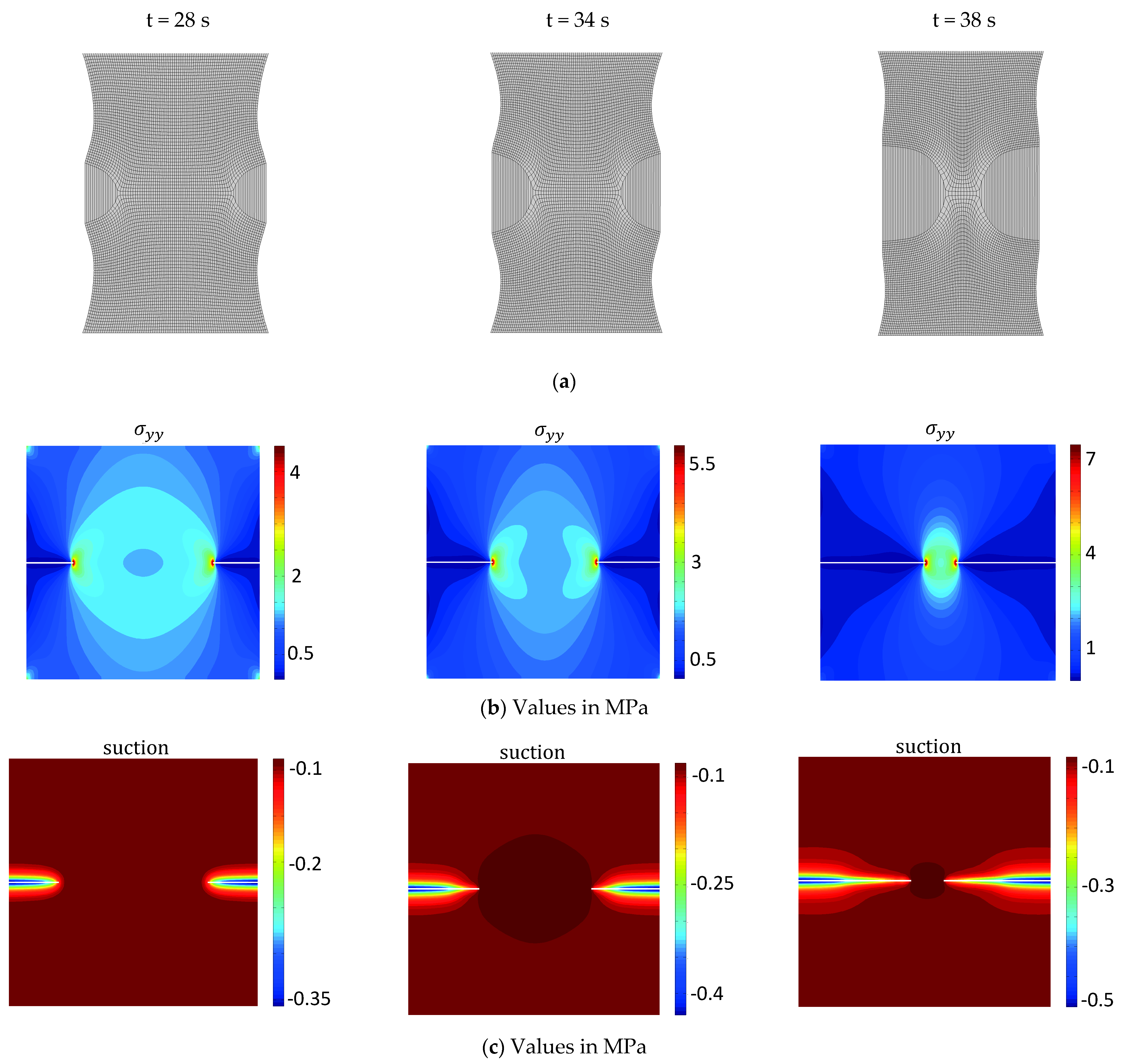
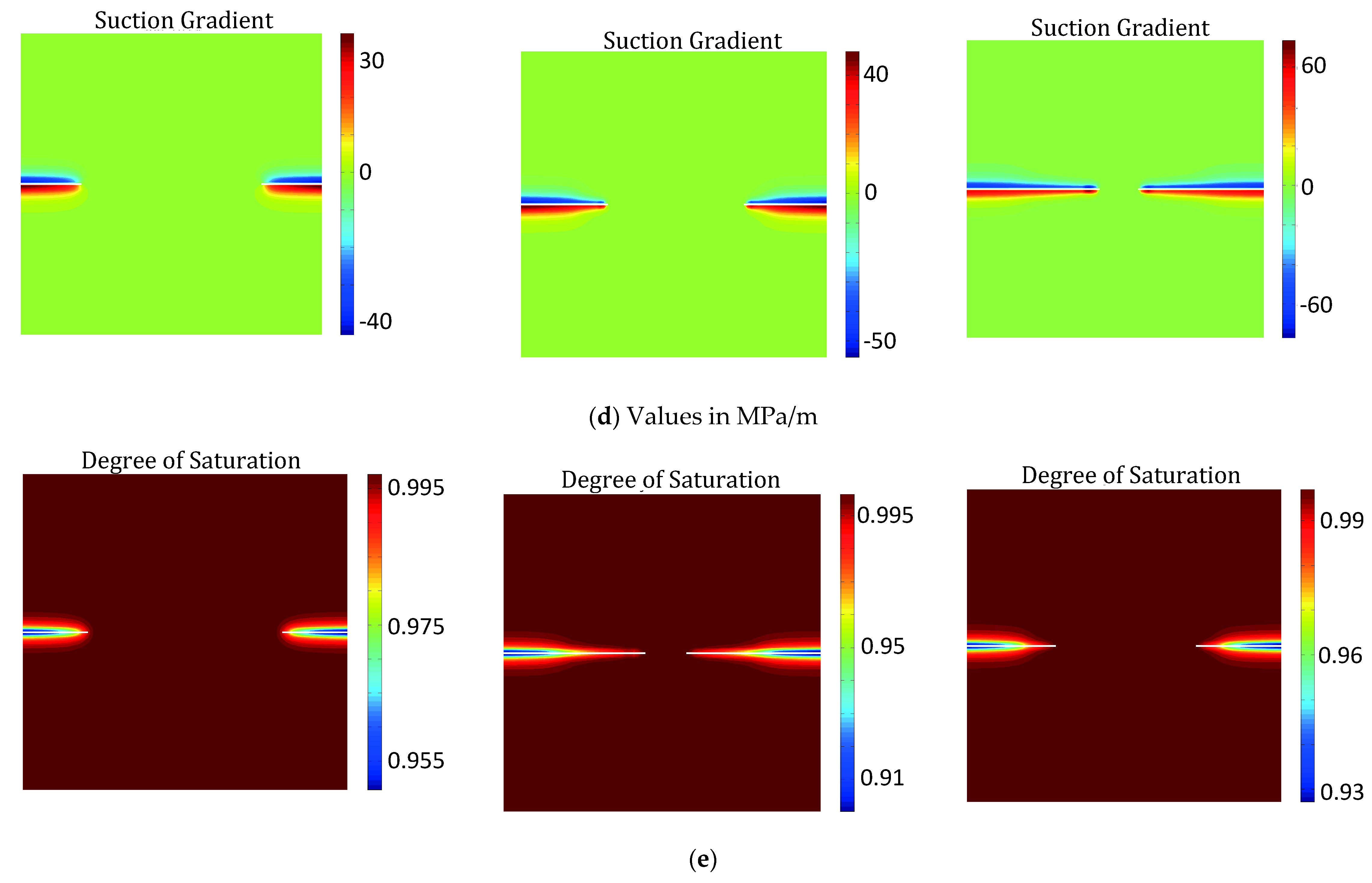
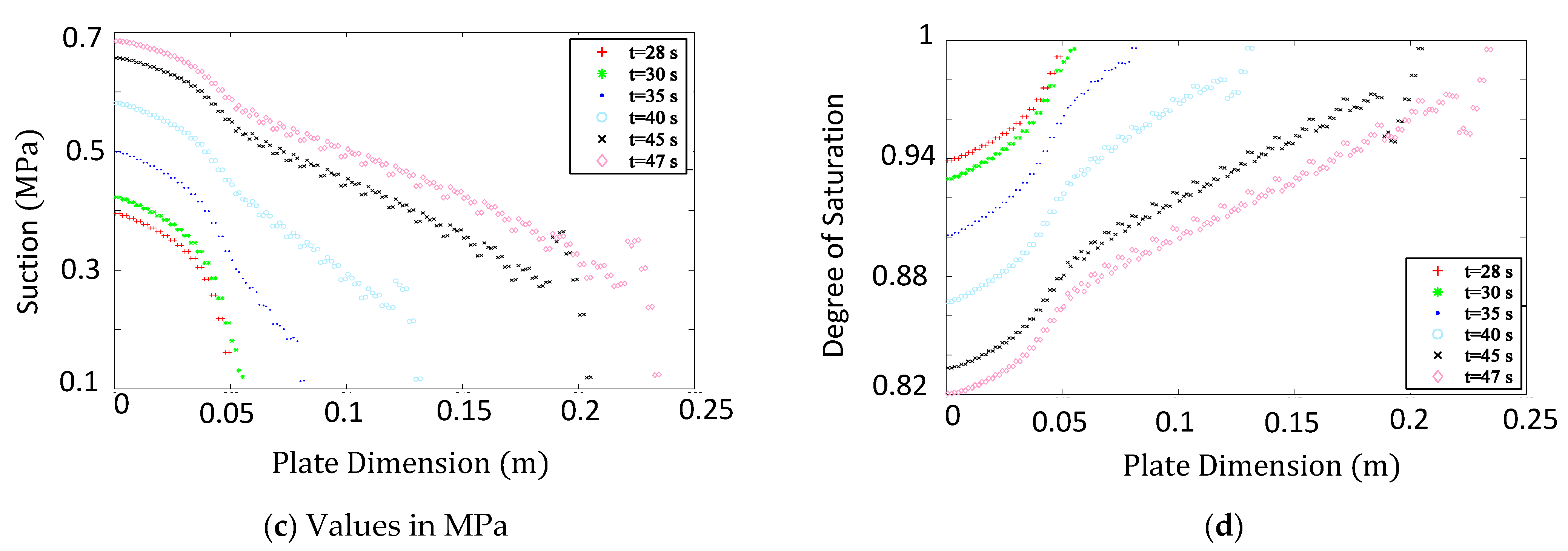
The normal gradient of the suction presented in Figure 4d indicates moisture leakage flux. The normal gradient of suction has opposite values on the two sides of discontinuities, and the difference between normal gradients of suction on two sides of fractures activates the leakage flux term. As a consequence of moisture leakage flux, moisture is absorbed to the discontinuity, and it ends in the change of water content around the cracks. Thus, as depicted in Figure 4c, the degree of saturation decreases around the cracks.
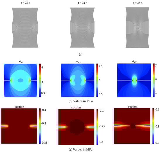
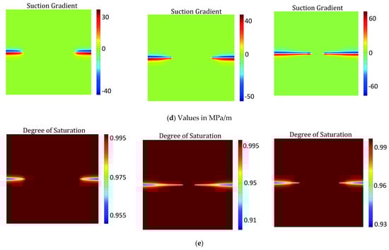
Figure 4.
(a) Plate Deformation, (b) Normal Stress, (c) Suction, (d) Normal suction gradient, and (e) Degree of saturation distributions at different times for the problem one—the square plate with initial existing crack stretched out with the constant displacement rate of .
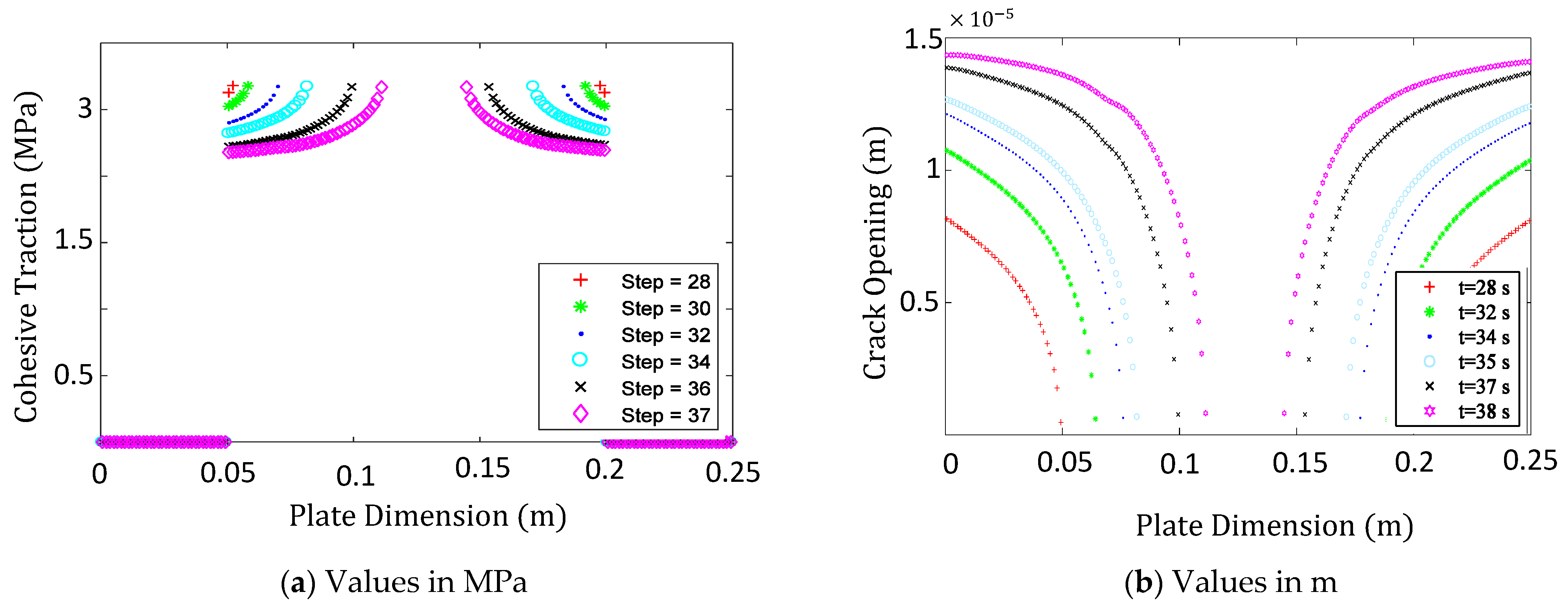
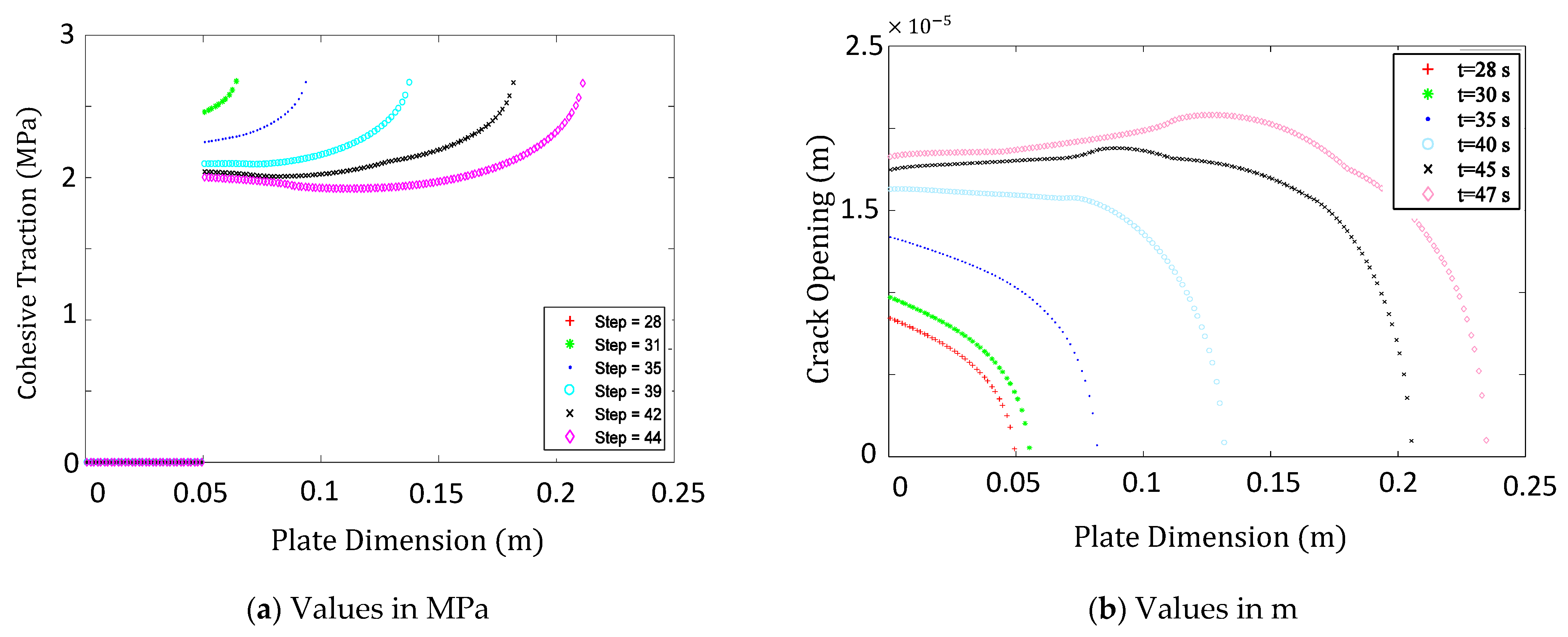
To better analyze the distribution of the cohesive traction along the crack, the normal stress and crack opening at different times of crack propagation are presented in Figure 5a,b, respectively. As the crack propagates, traction-separation force is applied to the crack body. It is clear that the stress value at the crack tip reaches the cohesive strength of the material where the crack has zero openings. The value of cohesive traction decreases from tensile strength for zero openings to zero for initial notches.
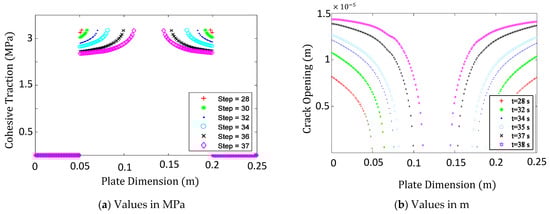
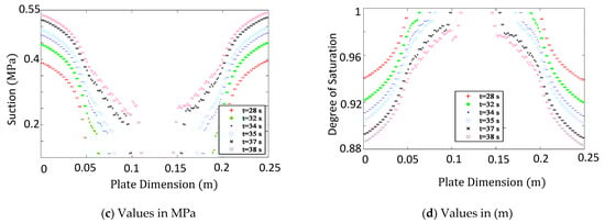
Figure 5.
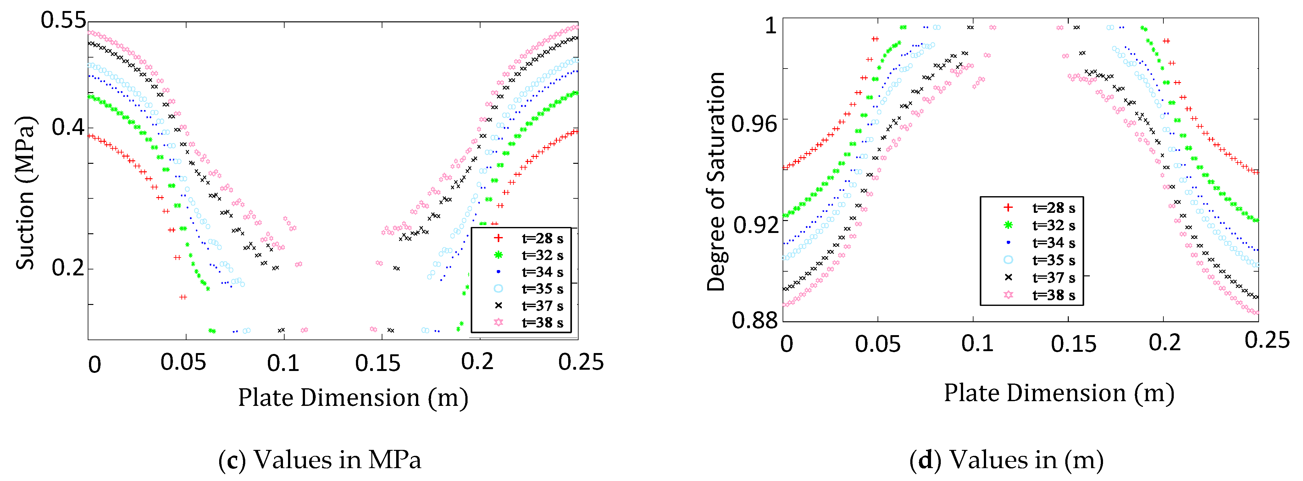
(a) Cohesive traction distribution, (b) Crack opening, (c) Suction distribution, and (d) Degree of Saturation at different times for Problem 1 (a square plate with initial existing crack depicts in Figure 3).
To minimize the crack opening and inhibit crack propagation, as is shown in Figure 5c, the suction increases around the fracture. As the crack opening increases at a specific point, the exerted cohesive force on the crack body decreases. At that point, suction plays a more active role as a preventative force against the crack opening. Still, since the intensity of suction is much lower than the cohesive force, its influence on the reduction in the crack aperture at that point is less that the cohesive force influence. As depicted in Figure 5d, the degree of saturation is also significantly affected by the presence of the cracks and varies intensely along the crack up to the maximum value of one at the crack tip where the crack is closed and there is no leakage flux.
To better understand the impact that the presence of two cracks has on the unsaturated porous plate behavior, a comparison is made with the case when a single crack propagates from the left edge of the same plate. The distributions of various variables for the case of single crack propagation are presented in Figure 6 at different times.
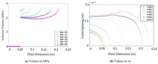
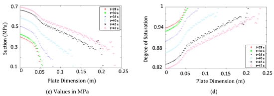
Figure 6.
(a) Cohesive traction, (b) Crack opening, (c) Suction, and (d) Degree of saturation distributions at different times in the case of one existing initial crack—the goal of this result is to make a comparison with the case of two existing initial crack.
As expected, the distributions of cohesive traction imposed on the crack body have the same upper limit in the two cases of one and two cracks. However, since the crack mouth opening in the final steps of single crack case analysis is more than its double crack counterpart (see Figure 5b and Figure 6b), and as cohesive force depends directly on the crack opening, cohesive force at the crack mouth of single crack case analysis becomes less than its double crack counterpart at the final steps (Figure 5a and Figure 6a). To compensate for a less cohesive force in a single crack case, the crack mouth suction increases more in this case than its double crack equivalent to prevent further crack mouth opening. This behavior accentuates the preventative role of suction to inhibit crack propagation. In addition, this comparison depicts the ability of the proposed model in its successful demonstration of natural force for preventing crack to propagate.
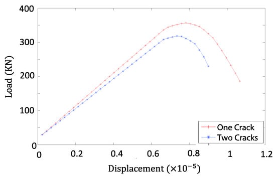
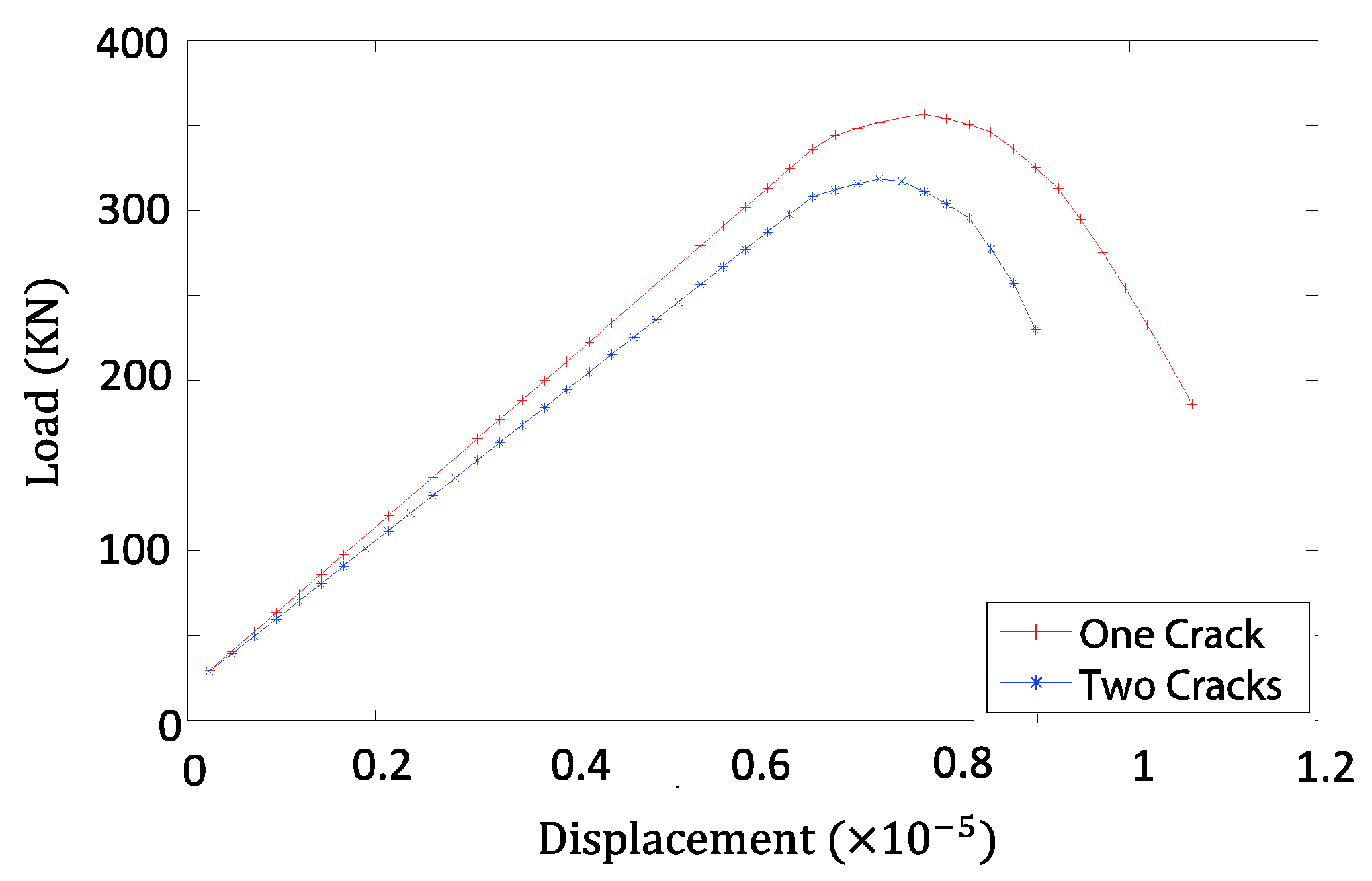
To compare the load carrying capacity of the plate in the presence of two cracks with the case of single crack, load–displacement curves for the two cases are depicted in Figure 7. Since in the case of double cracks, the load is transferred via the suction instead of the solid matrix in a longer width along with the plate, two graphs are different from the beginning. The higher load carrying capacity is observed in the case of a single crack, the more displacement is observed to reach the failure of the plate.
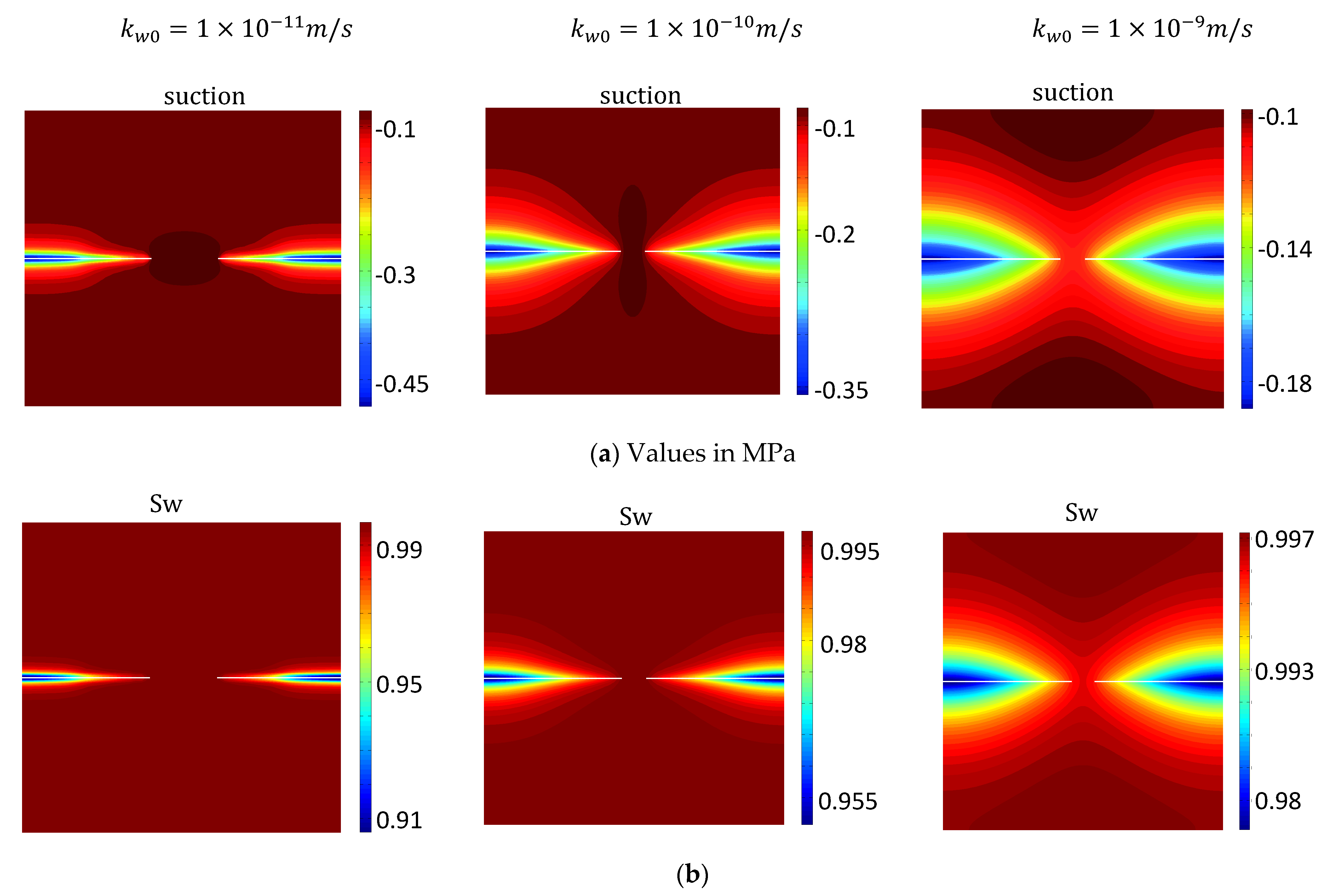
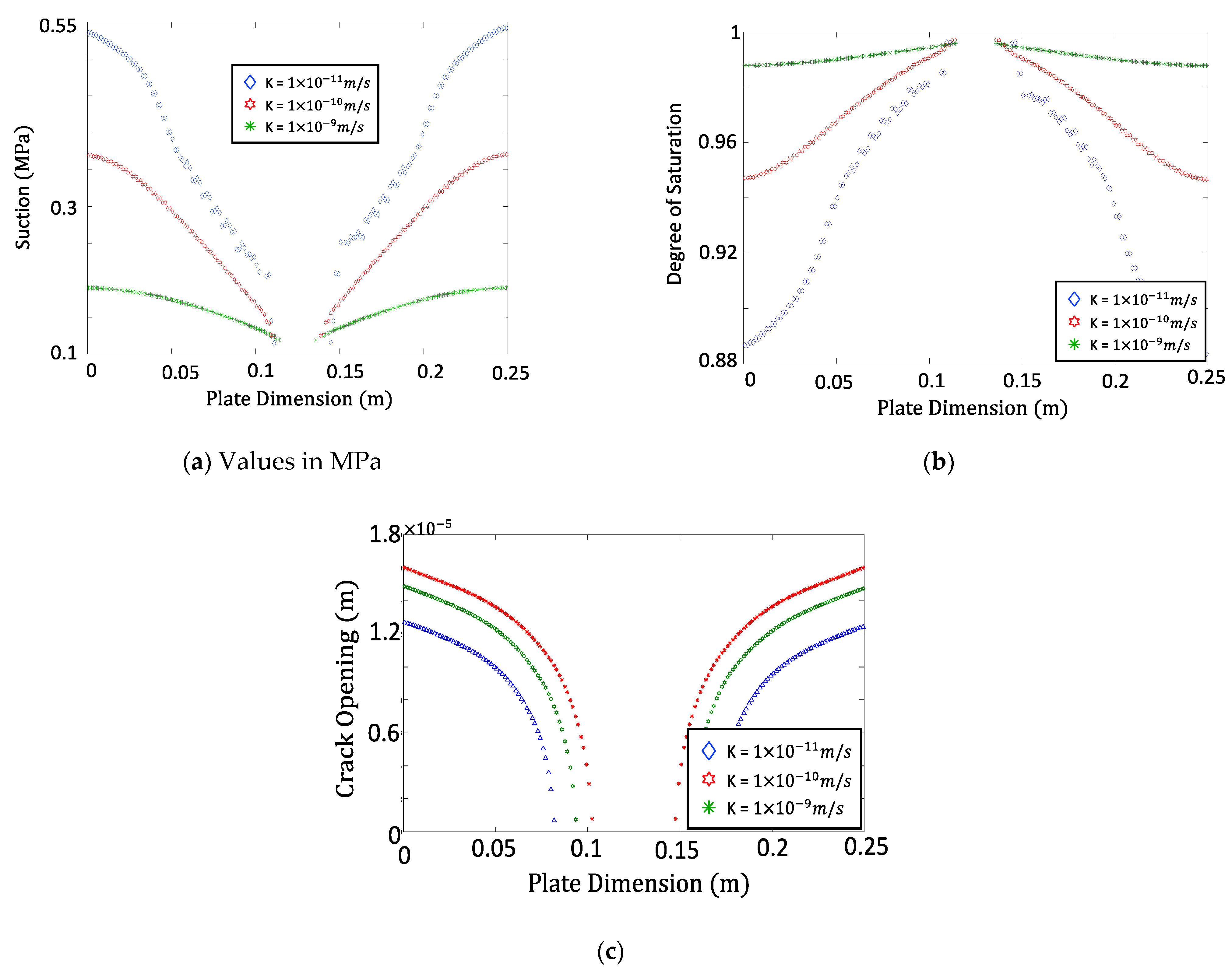
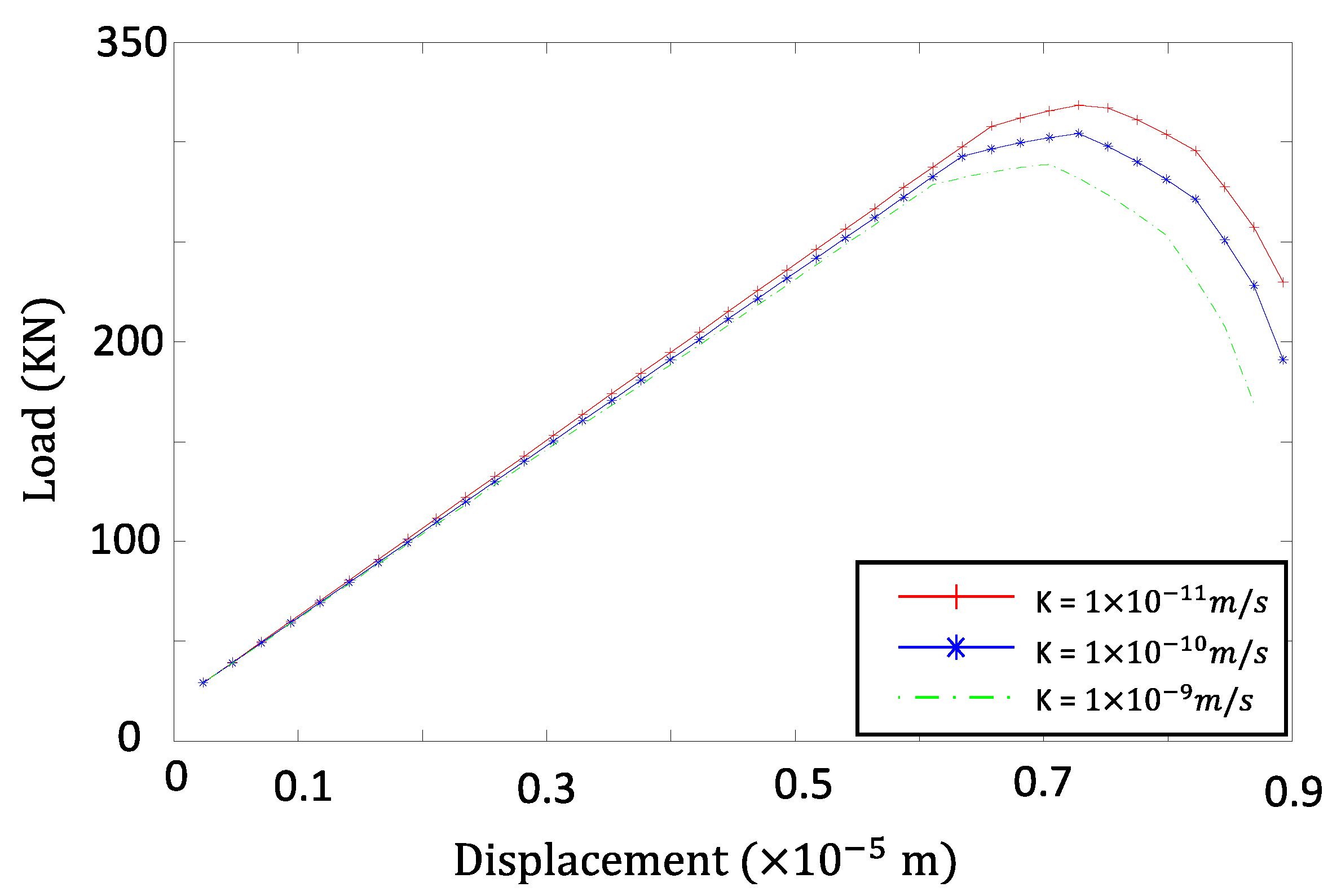
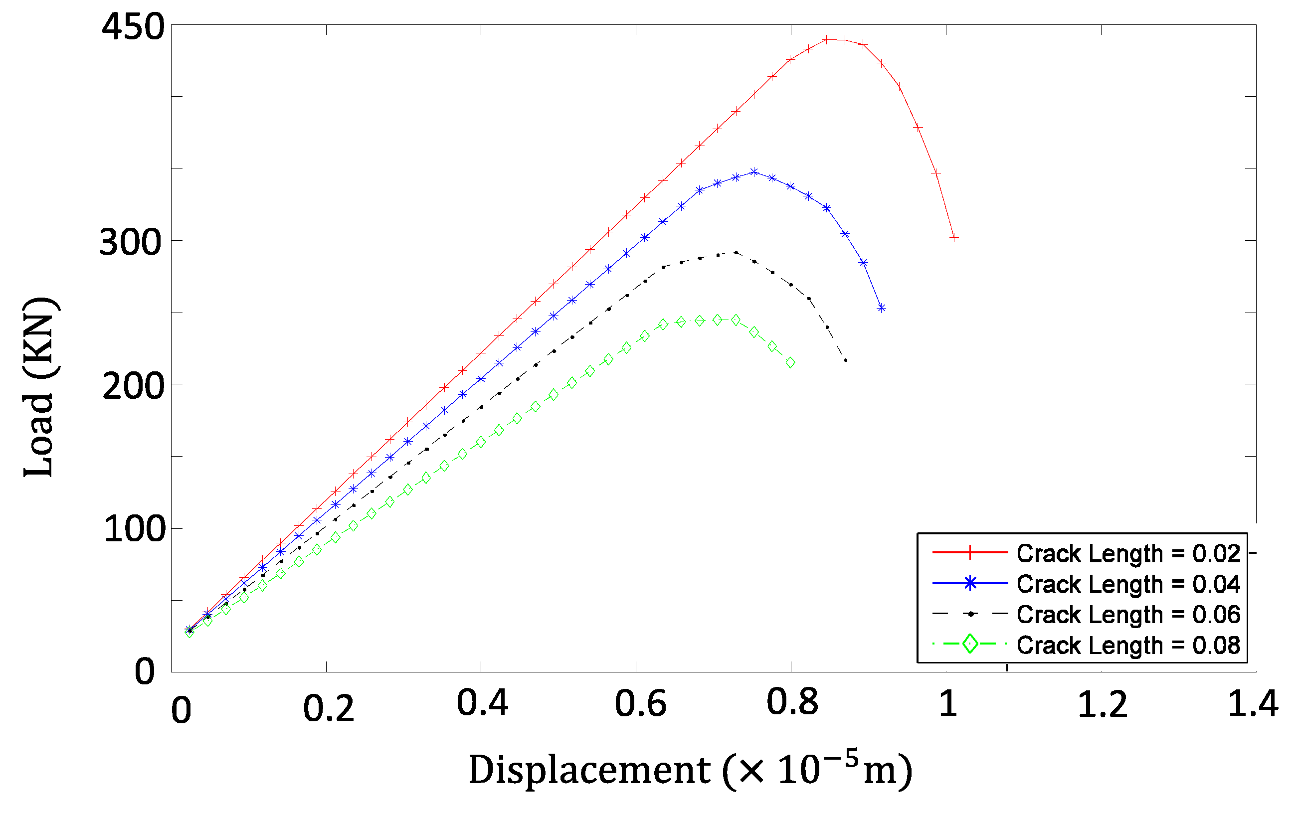
Sensitivity analysis is further performed to investigate the effect of permeability and initial crack length on the propagation of two cracks in the unsaturated porous plate. A series of reference permeability values and initial crack lengths are adopted to examine their influences on the response of the model. When the reference permeability is high, much fewer suction gradients are required for water exchange that leads to lower suction around the fracture (Figure 8a), which results in higher normal displacement (Figure 9c). With lower permeability, on the other hand, the water exchange needs a higher suction gradient that affects a smaller zone around the crack (Figure 8). This larger suction gradient generates higher suction, reducing the crack opening displacement (Figure 9c). The load carrying capacity curves of the plate for different intrinsic permeabilities that are shown in Figure 10 are supportive of the previous explanation. As intrinsic permeability decreases, suction increases around the crack, and the ultimate bearing capacity of the plate rises. To investigate the effect of initial crack length, as the initial crack length increases, load carrying capacity of plate decreases (Figure 11) since the initial stiffness of plate decreases.
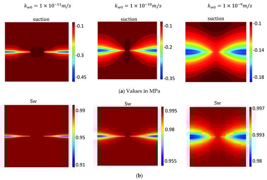
Figure 8.
(a) Suction and (b) Degree of saturation distributions for different intrinsic permeabilities at the time of 38 s (the effect of permeability on the proposed model considering two existing initial cracks).
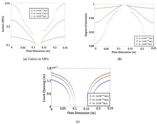
Figure 9.
(a) Suction, (b) Degree of saturation, and (c) Crack opening distributions for different permeabilities at the time of 38 s (the effect of permeability in the proposed model considering two existing initial cracks).
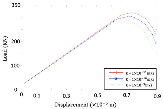
Figure 10.
Load–displacement curves for different intrinsic permeabilities (the effect of permeability on proposed model considering two existing initial cracks).
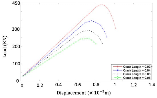
Figure 11.
Load–displacement for different initial crack lengths (the effect of initial crack length on the proposed model considering two existing initial cracks).
3.2. Crack in a Drying Wall
In this example, we design a problem of masonry wall associated with climate change. The stability issues of the masonry wall are usually caused by the difference of the mechanical and thermal properties between the bricks and their joins, which are mostly made up of mortar. Due to this feature of masonry wall, cracks can be easily triggered and propagated, which can be further accelerated due to a severe change of the environmental condition, that is, the thermal difference between the inside and outside of the wall. In order to show the capabilities of the proposed model, the simulation of a failure of masonry wall under environmental loading is investigated.
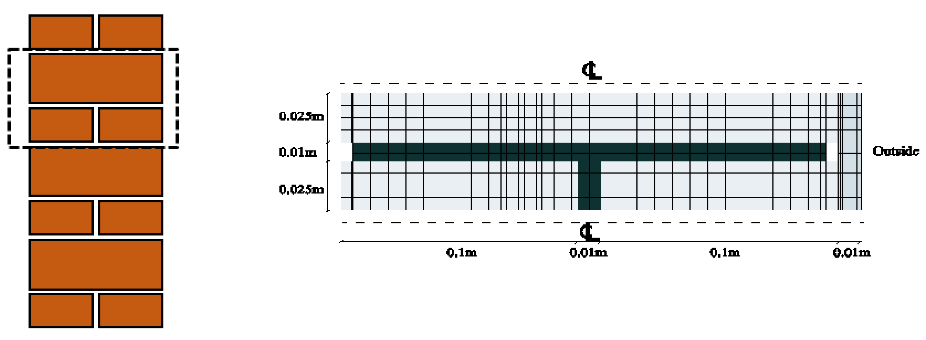
In this problem, a cross section of two wythes common band of masonry wall is considered in Figure 12. The left figure depicts the whole cross section of a two wythes common band of masonry wall, where a representative part of the wall for modeling is presented in the right figure. A brick is used on the upper part of the wall, while two bricks are placed on its lower part. The bricks’ dimensions are presented on Figure 12, and a thin layer of mortar with a thickness of 0.01 m is used between them (dark gray color). The outer surface of the wall is insulated with a 0.01-meter plaster, while no plaster is considered on the inner surface of the wall.
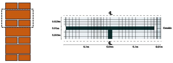
Figure 12.
The geometry and mesh of the model—the area depicted with dash line (left) is modeled in Problem 2. To the centerline for the right figure (CL) boundary condition is applied.
For spatial discretization of the model, 2210 bilinear elements are used that their boundaries are matched with material interfaces. The displacements in the y-direction of elements along the axis of symmetry of the model (C.L line) are bounded to zero and no moisture and heat exchanges with the external environment are considered for those elements. The displacement of the node on the bottom-left of the model is restricted in the x-direction to prevent its rigid body motion. The effects of gravity are neglected, and the inner and outer surfaces of the model are exposed to the environment, i.e., they could exchange moisture and heat with the environment. For the moisture exchange with the environment through evaporation or condensation, the following relation is used:
where is the mass transfer coefficient that is considered to be equal to for the outdoor environment and for the indoor environment. and are environmental and model vapor pressures, respectively [22]. Vapor pressure is obtained from the following equation:
where is the saturated vapor pressure per Pascal, which is retrieved from the following [22]:
It is assumed that the outdoor environment has a temperature of 40 °C and relative humidity of 50%. The temperature and relative humidity of indoor environment are taken equal to 10 °C and 85%, respectively. The model is assumed to be intact initially. The nonlocal stress criterion is checked, along with the loading sequence. If the nonlocal stress passes the tensile strength of the corresponding material, the fracture is embedded into that element.
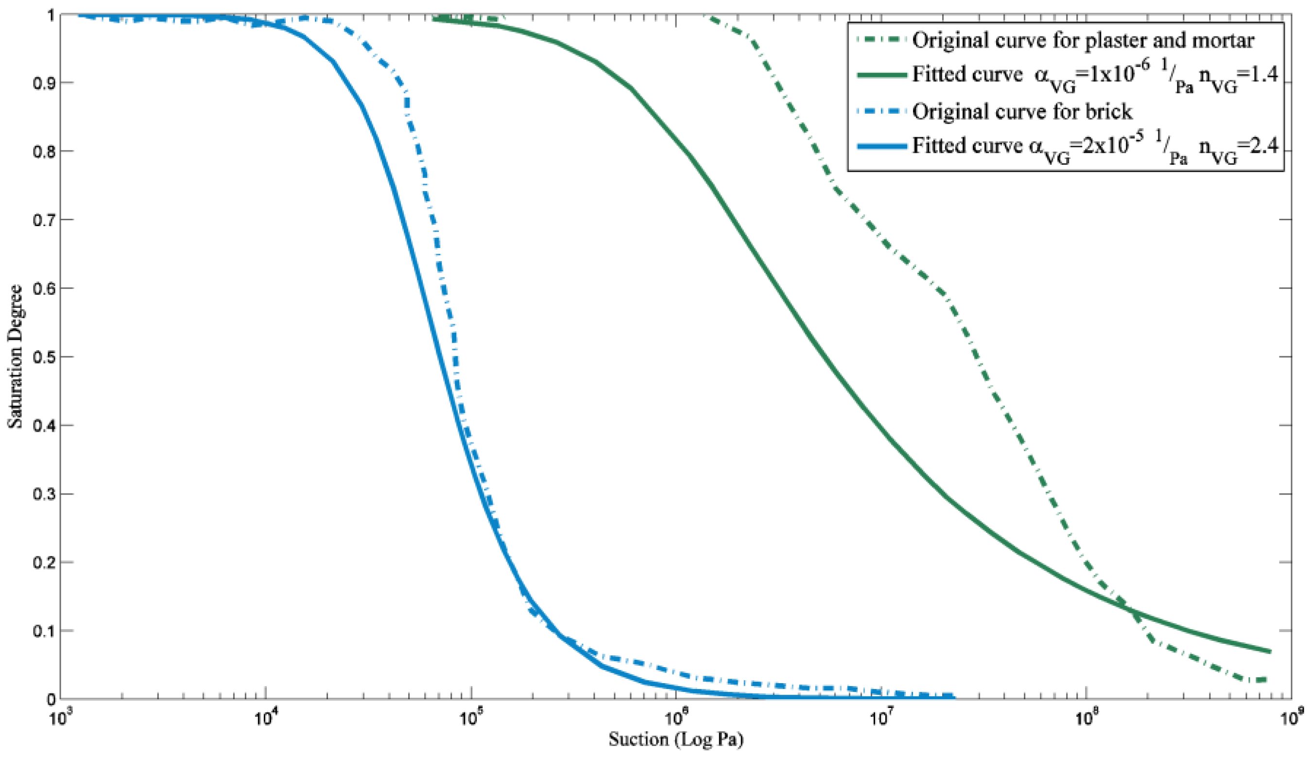
Material properties used in the numerical simulations are given in Table 2. To determine the coefficients of the state surface of the degree of saturation for brick and plaster, the state surfaces’ parameters are looked after that have the best fit to proposed surfaces of [22]. If and for brick and and for plaster are considered (Equation (5)), a good agreement is found with recommended surfaces of [22] Figure 13.
Table 2.
Material properties for Problem 2 of plaster on the wall.

Figure 13.
State surfaces of the degree of saturation of different materials: the coefficients of the state surface of the degree of saturation (Equation (5)) for brick and plaster, state surfaces parameters are looked after that have the best fit to proposed surfaces of [22].
At the first step of the simulation, the moisture reduces quickly in the surface layer of the plaster. To make up for the moisture reduction in the surface layer, moisture flows from bricks toward the plaster. Since the air entry pressure is much more in the plaster than in the bricks, as is shown in Figure 14c, the degree of saturation reduces more in the bricks compared to the plaster at their interface. As the cavity behind the plaster hinders the absorption of moisture by the plaster, the shrinkage of the plaster will not be uniform, and the plaster bulges to the cavity. The maximum stress that develops in the inner surface of plaster in place of the cavity causes nucleation of fracture in the plaster.
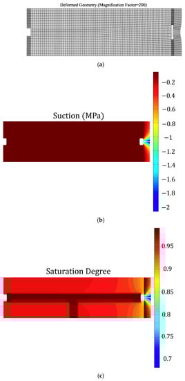
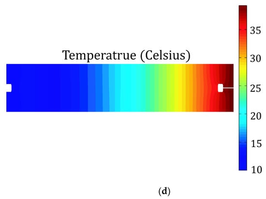
Figure 14.
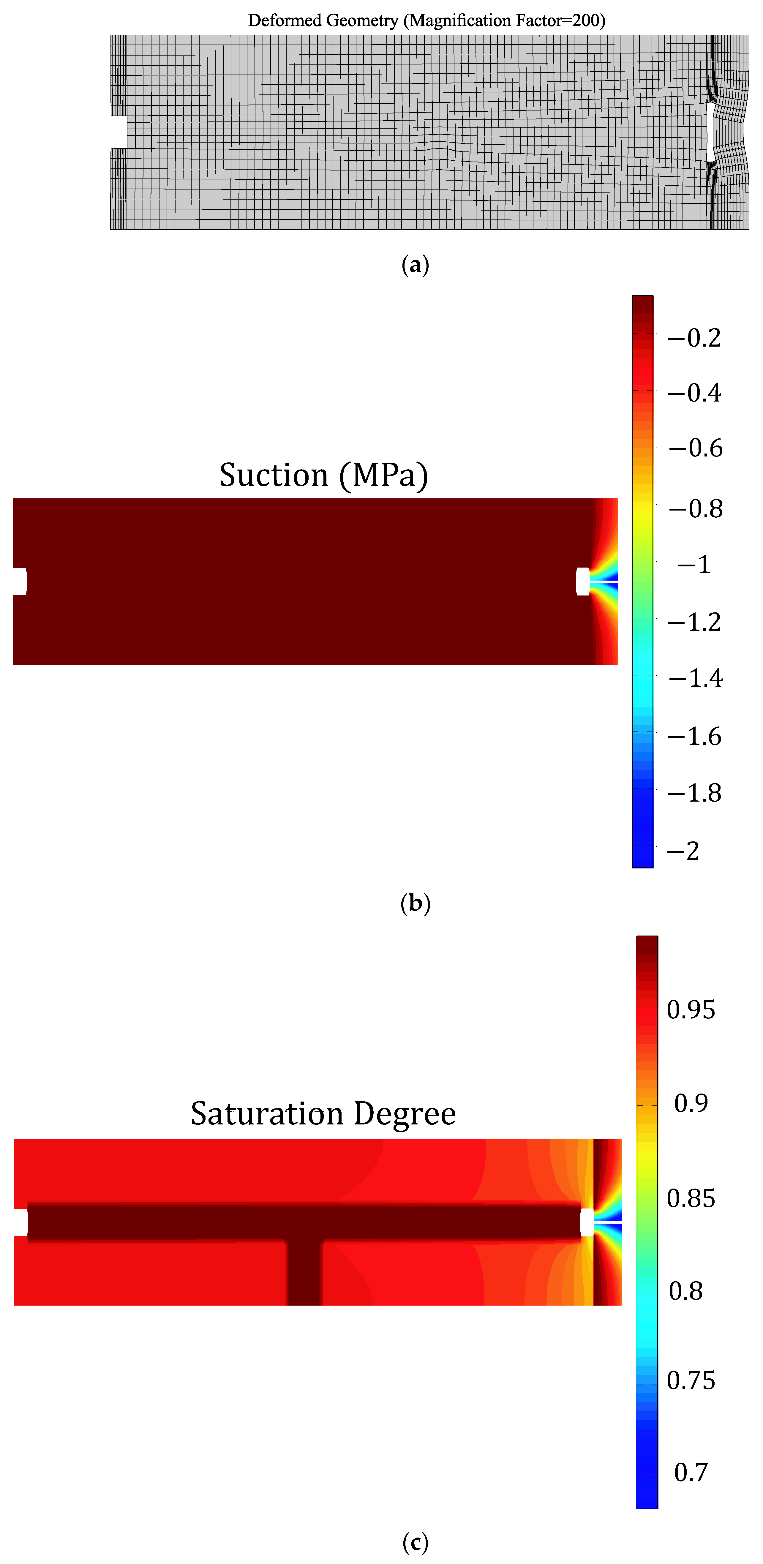
(a) Deformation, (b) Suction, (c) Degree of saturation, and (d) Temperature of the wall two hours after the start of analysis for Problem 2.
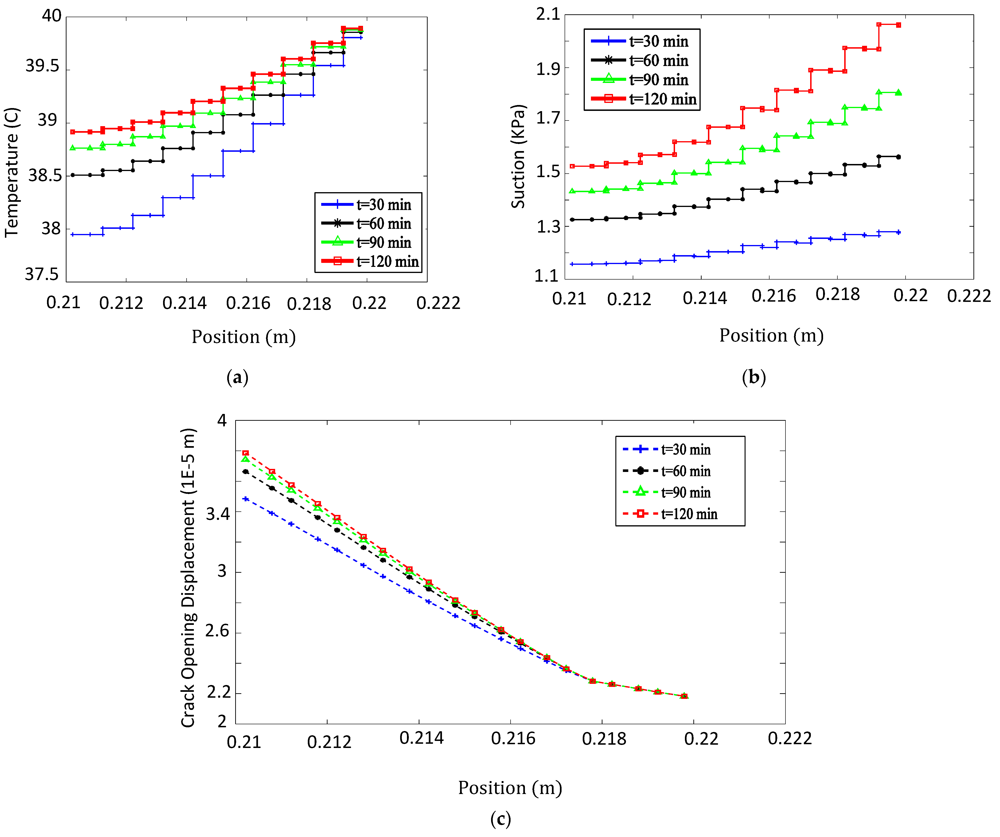
With the continuation of drying, the crack progresses and bisects the plaster in the initial steps of simulation. The increase in temperature along the crack over time (Figure 15a) leads to the drying of plaster in the neighborhood of the crack, followed by the increase in suction around the crack (Figure 15b) that prevents excessive changes of opening along the crack due to the drying (Figure 15c). In other words, as a result of the increasing temperature, the degree of saturation decreases (Figure 14c) with increasing suction (Figure 14b) that prevents the crack from further propagation. This process limits an excessive change of opening along the crack (Figure 15c).
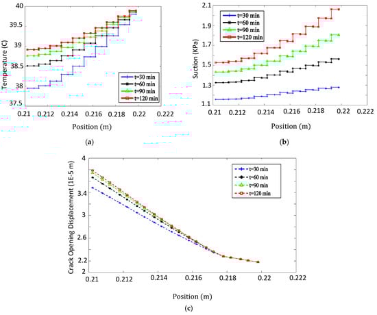
Figure 15.
The variation of (a) temperature, (b) suction, and (c) opening along the crack at different times for Problem 2.
The deformation and distribution of suction, saturation, and wall temperature two hours after the beginning of the analysis are shown in Figure 14. As the crack opens, suction increases around the crack (Figure 14b) to prevent further fracture opening. The growth of the suction causes absorption of the moisture to the crack and reduction in the degree of saturation in the proximity of the crack (Figure 14c).
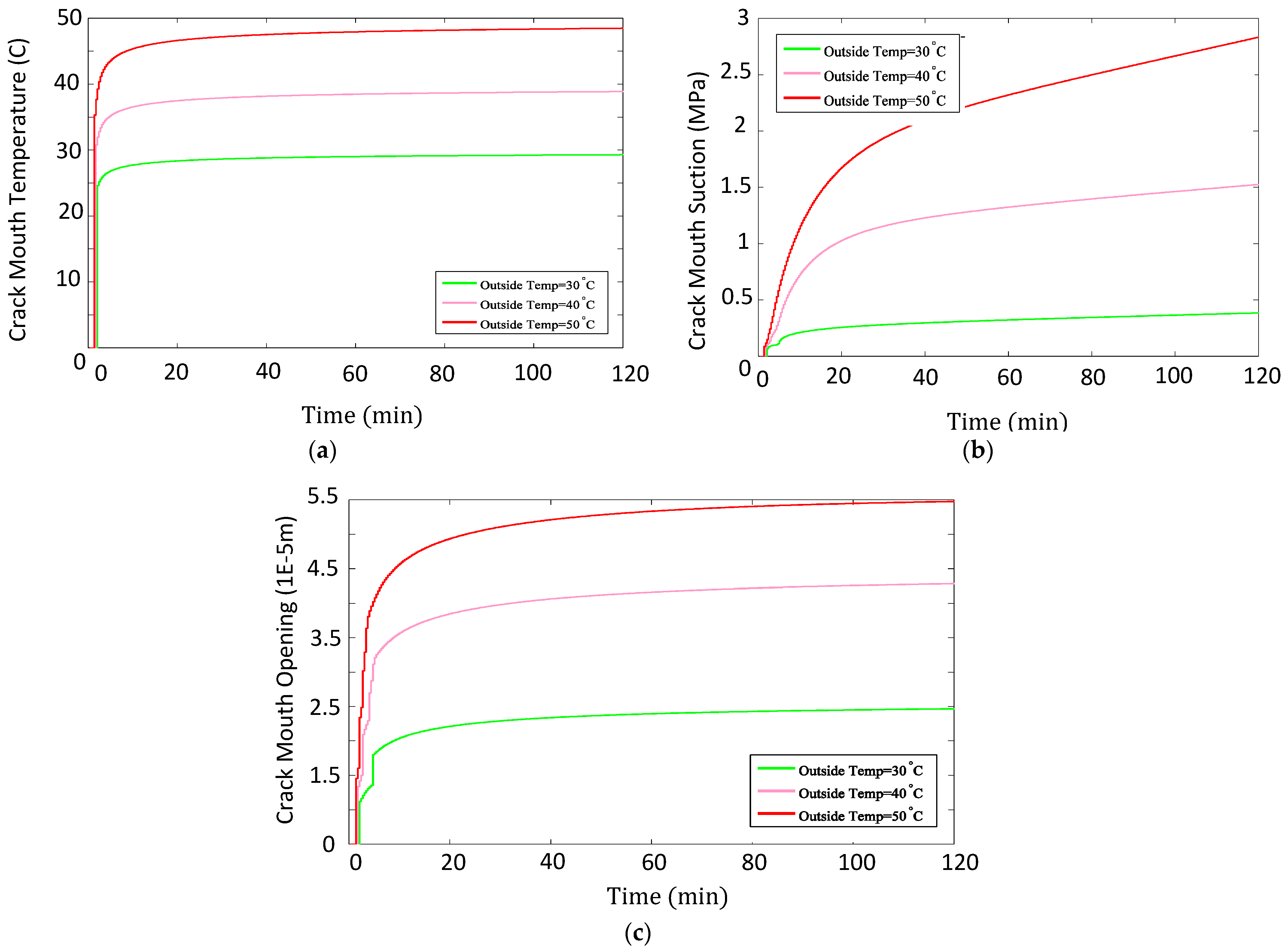
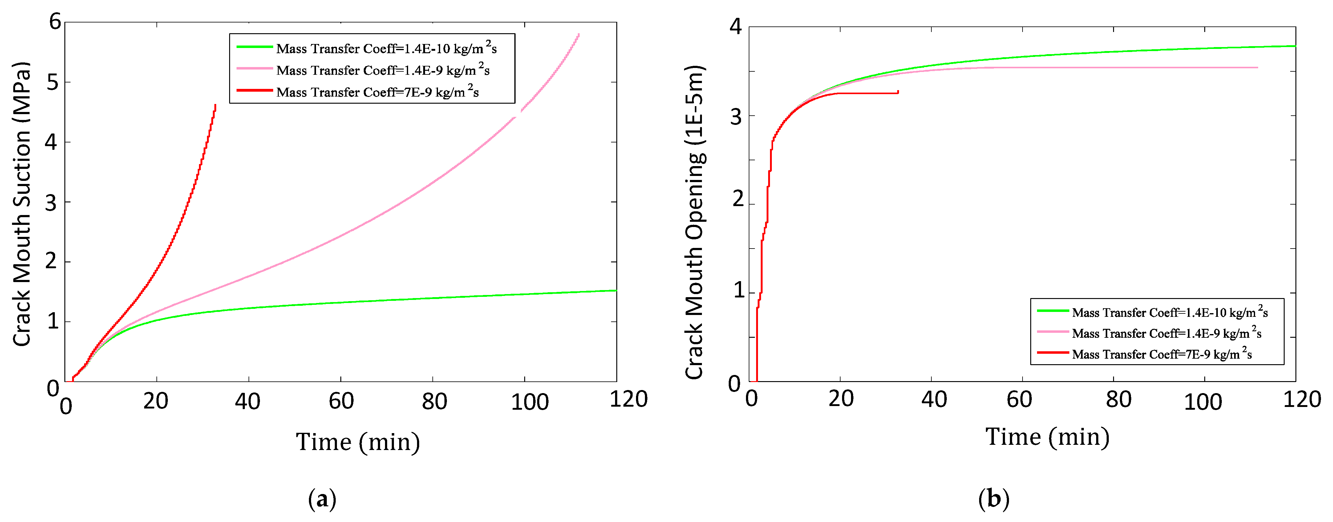
The effects of the outside temperature and mass transfer coefficient are investigated on the obtained results. In addition to the exterior temperature of 40 °C, two temperatures of 30 and 50 °C are considered as outside temperatures as well. By increasing the temperature of the outdoor environment and as the time passes, the temperature increases at the crack mouth (Figure 16a). The rise in the temperature at the crack mouth induces more drying and, hence, more suction at the crack mouth (Figure 16b), but as it is evident in Figure 16c, the increased suction at the crack mouth is insufficient to reduce the crack’s mouth opening displacement (CMOD) as outside temperature rises. In order to study the response of the model to the outside mass transfer coefficient, two values of and are considered in addition to the present mass transfer coefficient for the outdoor environment. As the mass transfer coefficient increases for the outdoor environment, surface drying of the plaster happens faster, and suction increases more at the mouth of the crack (Figure 17a). The increase in the suction due to the rise of the mass transfer coefficient reaches the extent that leads to the decline of CMOD (Figure 17b), but as drying of the plaster happens faster, the analyses terminate prematurely for higher mass transfer coefficients.

Figure 16.
Variations of (a) temperature, (b) suction, and (c) opening at the crack mouth over time for different outside temperatures. In this figure, we investigated the effects of outside temperature on the failure of the wall.
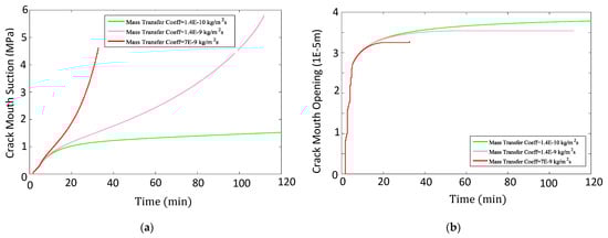
Figure 17.
Variations of (a) suction and (b) opening at the crack mouth over time for different mass transfer coefficients. In this figure, the effect of mass transfer coefficient on the failure of the wall is examined (Equation (19)).
4. Conclusions
Fracture and damage in unsaturated porous media can be caused by a tensile crack (due to mechanical loading), thermal crack (temperature difference), and shrinkage crack (loss of moisture). This cracking is a complex behavior that is due to multiphase (solid, fluid, gas, and heat) interactions. With respect to climate change, environmental loading may accelerate the instability of unsaturated porous media, which may comprise practical problems including slope stability, retaining wall, masonry wall, etc., under cyclic wetting and drying or extreme heatwave. Therefore, simulating the damage behavior of a multiphase non-isothermal system is essential to understand such failures properly.
In this study, we have designed two numerical examples to simulate potential failure scenarios associated with climate change to better understand its impact on unsaturated porous media. The previous study [23] has been recast and improved to capture a heat and moisture flow associated with the fracture of unsaturated porous media. The proposed model combines the simultaneous movement of moisture and heat in deformable porous media with a cohesive crack model, which employs the extended finite element method (XFEM) to include strong and weak discontinuities in the model framework.
In the first example, the tracking functions of cracks are modified, and the local exchange of flows is calculated for each crack for the consideration of multiple crack propagation. Suction, cohesive traction, saturation degree, crack opening, and load displacement are compared for the case of two crack propagation in an unsaturated plate with the single crack propagation in that plate. The effects of parameters such as intrinsic permeability and initial crack length on the obtained results are studied. When intrinsic permeability and initial crack length decrease, the applied suction to crack faces increases, and the plate could sustain higher loads and raptures later in the analysis. In the second example, the degradation of a masonry wall due to climatic loading is investigated. As the plaster on a brick wall dries, it shrinks, and a crack is formed on the unrestricted part of it when it deforms in the cavity between the bricks. Suction surges along the crack and prevents excessive crack opening. When the temperature rises in the outside environment, suction rises at the crack mouth, but this increased suction cannot reduce crack mouth opening displacement (CMOD). As the mass transfer coefficient of the outside environment rises, the suction increases at the crack mouth and reduces CMOD, but since the plaster dries faster, the analysis terminates prematurely. The results of numerical tests demonstrate the capabilities of the proposed model for practical application associated with climate change well.
Author Contributions
Conceptualization, A.M.V., E.M.H., and B.G.; writing—original draft preparation, E.M.H. and A.M.V.; writing—review, improve, and editing, S.N. All authors have read and agreed to the published version of the manuscript.
Funding
This research received no external funding.
Institutional Review Board Statement
Not applicable.
Informed Consent Statement
Not applicable.
Data Availability Statement
The data presented in this study are available on request from the corresponding author.
Acknowledgments
We would like to gratefully acknowledge the advice and comments of Peter Moonen and Soheil Mohammadi, their help was invaluable.
Conflicts of Interest
The authors declare no conflict of interest.
References
- Arson, C.; Gatmiri, B. Numerical study of a thermo-hydro-mechanical damage model for unsaturated porous media. Ann. Solid Struct. Mech. 2010, 1, 59–78. [Google Scholar] [CrossRef]
- Barenblatt, G.I. The mathematical theory of equilibrium cracks in brittle fracture. Adv. Appl. Mech. 1962, 7, 55–129. [Google Scholar] [CrossRef]
- Fang, H.-Y.; Chaney, R.C. Introduction to Environmental Geotechnology; CRC Press: Boca Raton, FL, USA, 2016. [Google Scholar]
- Thomas, H.R.; He, Y. Analysis of coupled heat, moisture and air transfer in a deformable unsaturated soil. Géotechnique 1995, 45, 677–689. [Google Scholar] [CrossRef]
- Philip, J.R.; de Vries, D.A. Moisture movement in porous materials under temperature gradients. Eos Trans. Am. Geophys. Union 1957, 38, 222–232. [Google Scholar] [CrossRef]
- Gatmiri, B. Analysis of Fully Coupled Behaviour of Unsaturated Porous Media Under Stress, Suction and Temperature Gradient; Final report of CERMES-EDF. 1997. [Google Scholar]
- Nassar, I.N.; Horton, R. Heat, Water, and Solution Transfer in Unsaturated Porous Media: I—Theory Development and Transport Coefficient Evaluation. Transp. Porous Media 1997, 27, 17–38. [Google Scholar] [CrossRef]
- Lu, N.; Dong, Y. Closed-form equation for thermal conductivity of unsaturated soils at room temperature. J. Geotech. Geoenviron. Eng. 2015, 141, 04015016. [Google Scholar] [CrossRef] [Green Version]
- Gatmiri, B.; Arson, C. θ-STOCK, a powerful tool of thermohydromechanical behaviour and damage modelling of unsaturated porous media. Comput. Geotech. 2008, 35, 890–915. [Google Scholar] [CrossRef]
- Olivella, S.; Gens, A.; Carrera, J.; Alonso, E.E. Numerical formulation for a simulator (CODE_BRIGHT) for the coupled analysis of saline media. Eng. Comput. 1996, 13, 87–112. [Google Scholar] [CrossRef] [Green Version]
- Giraud, A.; Giot, R.; Homand, F. Poromechanical Modelling and Inverse Approach of Drying Tests on Weakly Permeable Porous Rocks. Transp. Porous Media 2008, 76, 45–66. [Google Scholar] [CrossRef]
- Carpinteri, A.; Colombo, G. Numerical analysis of catastrophic softening behaviour (snap-back instability). Comput. Struct. 1989, 31, 607–636. [Google Scholar] [CrossRef]
- Dugdale, D.S. Yielding of steel sheets containing slits. J. Mech. Phys. Solids 1960, 8, 100–104. [Google Scholar] [CrossRef]
- Hillerborg, A.; Modéer, M.; Petersson, P.-E. Analysis of crack formation and crack growth in concrete by means of fracture mechanics and finite elements. Cem. Concr. Res. 1976, 6, 773–781. [Google Scholar] [CrossRef]
- Yang, B.; Ravi-Chandar, K. A single-domain dual-boundary-element formulation incorporating a cohesive zone model for elastostatic cracks. Int. J. Fract. 1998, 93, 115–144. [Google Scholar] [CrossRef]
- Rabczuk, T.; Zi, G. A Meshfree Method based on the Local Partition of Unity for Cohesive Cracks. Comput. Mech. 2007, 39, 743–760. [Google Scholar] [CrossRef]
- Amarisiri, A.; Shannon, B.; Kodikara, J. Numerical modelling of desiccation cracking in a restrained ring test. Can. Geotech. J. 2014, 51, 67–76. [Google Scholar] [CrossRef]
- Moes, N.; Belytschko, T. Extended finite element method for cohesive crack growth. Eng. Fract. Mech. 2002, 69, 813–833. [Google Scholar] [CrossRef] [Green Version]
- Réthoré, J.; de Borst, R.; Abellan, M.-A. A two-scale approach for fluid flow in fractured porous media. Int. J. Numer. Methods Eng. 2007, 71, 780–800. [Google Scholar] [CrossRef]
- Réthoré, J.; de Borst, R.; Abellan, M.-A. A two-scale model for fluid flow in an unsaturated porous medium with cohesive cracks. Comput. Mech. 2008, 42, 227–238. [Google Scholar] [CrossRef] [Green Version]
- Mohammadi, S. Extended Finite Element Method: For Fracture Analysis of Structures; John Wiley & Sons: Hoboken, NJ, USA, 2008; ISBN 978-1-405-17060-4. [Google Scholar]
- Moonen, P.; Sluys, L.J.; Carmeliet, J. A continuous-discontinuous approach to simulate physical degradation processes in porous media. Int. J. Numer. Methods Eng. 2010, 84, 1009–1037. [Google Scholar] [CrossRef]
- Varnosfaderani, A.M.; Gatmiri, B.; Haghighi, E.M. A model for moisture and heat flow in fractured unsaturated porous media. Int. J. Numer. Anal. Methods Geomech. 2016, 41, 828–858. [Google Scholar] [CrossRef]
- Gatmiri, B.; Hoor, A. Effect of excavation on the thermo-hydro-mechanical behaviour of a geological barrier. Phys. Chem. Earth Parts A B C 2007, 32, 947–956. [Google Scholar] [CrossRef]
- Stolarska, M.; Chopp, D.L.; Moës, N.; Belytschko, T. Modelling crack growth by level sets in the extended finite element method. Int. J. Numer. Methods Eng. 2001, 51, 943–960. [Google Scholar] [CrossRef]

Publisher’s Note: MDPI stays neutral with regard to jurisdictional claims in published maps and institutional affiliations. |
© 2021 by the authors. Licensee MDPI, Basel, Switzerland. This article is an open access article distributed under the terms and conditions of the Creative Commons Attribution (CC BY) license (https://creativecommons.org/licenses/by/4.0/).