Abstract
Due to the serious impact of metro vibration on people’s lives, it is important to design vibration isolators. In this study, the dynamic characteristics of a thick-walled ring spring are studied first. Through theoretical derivation, a new formula suitable for thick-walled ring springs is proposed. Finite element numerical analysis was performed to study the load–displacement curve and stress of the ring spring and verified the correctness of the formula. According to the studied mechanic characteristics, a novel ring spring isolator is proposed for vibration isolation of the metro superstructure. With the help of a ring spring, the proposed isolator has good energy absorption and self-reset function. The dynamic simulations were conducted in a multi-story building with the ring spring isolator as the isolator to study the vibration performance. It is common knowledge that the vertical natural frequency of the superstructure that is isolated by compression springs is given by the mass of the superstructure and the spring stiffness. In order to obtain vibration attenuation and control the vertical deformation, the spring stiffness needs to be 500–1000 kN/mm. Hence, it is clear that the vibration isolator does reduce the vertical eigenfrequency. By comparing the isolated structure with the non-isolated structure, it is proved that the new isolator can effectively improve a building’s serviceability.
1. Introduction
As an important means to alleviate urban traffic pressure, the metro brings convenience to modern life. It also causes noise and vibration pollution in the metro superstructure and for neighboring residents. In recent years, complaints about traffic noise and environmental vibration have become international public issues. The environmental vibration of the underground reduces building comfort, affects human health and hinders the use of sensitive instruments [1]. Furthermore, it even affects the safety of old buildings.
To mitigate the negative impact of metro vibration on buildings, many scholars have carried out studies on the method of isolating vibration. Zou et al. [2,3,4] presented a 2D impedance model capable of predicting vibration transmission in column- and load-bearing wall-supported buildings. In terms of vibration isolation of buildings, the most commonly used types of vibration isolator are rubber, pneumatic and spring. Makoto et al. [5] used a 3D finite element method to study the deformation and stress distribution of rubber dampers which were subjected to strong earthquakes. Pan et al. [6] used thick natural rubber dampers and thick highly damping rubber supports to control the metro vibration. Ozdemir [7] used a bilinear hysteresis model to analyze a series of nonlinear responses of the vibration structure with lead rubber dampers, and studied the response of the lead core self-heating to the lead rubber damper under bidirectional earthquake action. All of them used rubber dampers for vibration isolation. They found that the rubber vibration isolator could have stable performance and low cost, but the vibration isolation effect is limited.
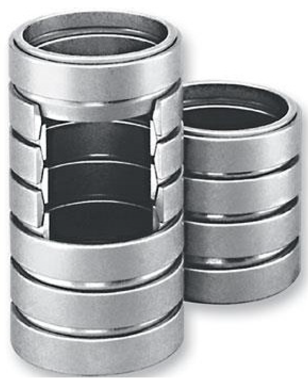
The ring spring, a kind of friction spring, is composed of multiple pairs of outer rings with inner cones and inner rings with outer cones (Figure 1) [8]. When axial load F acts on the ring and the normal component force acts on the conical surface of the inner rings and the outer rings, the outer ring will stretch and its diameter will expand, while the inner ring will compress, with its diameter shrinking. The relative movements of the rings along the conical surface cause them to press against each other and the spring produces axial deformation f.
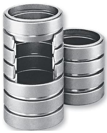
Figure 1.
Ring spring.
When the inner rings and the outer rings undergo a relative motion with each other on the conical surface, the contact surface generates friction. In this relative motion, the characteristic curves of loading and unloading do not coincide. As shown in Figure 2, the characteristic curve of the ring spring, the loading and unloading curves move along OABCO. When the ring spring is unloading, the stress–displacement curve starts from point B instead of point E. This is the reason why friction lags the elasticity of spring. If there is no friction, the loading and unloading will only act along OD. Obviously, the area of OABCO is the energy consumed by the internal friction and friction generated when the spring is working. During the loading process, the area of OABCD is about 60% to 70% of OAGO’s, which means the ring spring has a strong damping ability.
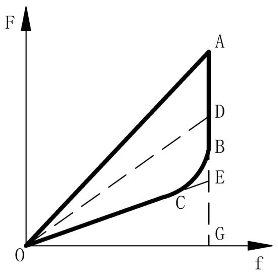
Figure 2.
Load–displacement curve of ring spring.
The pneumatic and hydraulic vibration isolator has excellent performance, but the design is too complicated to maintain [9]. It is not only expensive, but also difficult to promote. Meanwhile, the spring damper has good vibration isolation performance and consumes energy according to its vertical deformation and friction damping [10]. Currently, most spring dampers use helical springs and disc springs. The load–displacement curve of the helical spring is linear without an energy dissipation effect, so it needs to be used with dampers in the design of vibration isolators. [11]. Although disc springs and ring springs are both friction springs, the ring spring is more suitable when space is limited, thanks to its structural characteristics [12]. Furthermore, the energy storage capacity of ring springs is greater than that of disc springs. Briefly, the ring spring is more space-saving and economical than the disc spring [13]. Therefore, a new type of vibration isolator is developed in this study. This new vibration isolator has superior energy dissipation capabilities and self-reset function [14]. In addition, increasing the ring spring’s wall thickness can enhance its bearing capacity and stability.
2. Theoretical Derivation and Numerical Simulation of Ring Spring
2.1. Analytical Analysis
2.1.1. Stress
When the ring spring receives the axial force F, the inner ring generates compressive stress whereas the outer ring generates tensile stress. The contact surfaces of the inner rings and the outer rings both have compressive stress, thus producing tensile stress on the contact surface in the circumferential direction [15]. For the inner ring, the tensile stress offsets some of the inner ring’s compressive stress, so the inner ring’s maximum compressive stress is not on the contact surface, but on the cross-section. It will be more favorable for stress verification to not consider the compressive stress on the inner ring’s contact surface, but directly calculate the compressive stress caused by the circumferential component force [16], while in terms of the outer ring, the maximum tensile stress is generated on the inner surface of the outer ring after the tensile stress is combined with the compressive stress in the outer ring section. As for the strength ability, the maximum stress of both inner rings and outer rings should be smaller than the allowable stress.
The maximum compressive stress of the inner ring [8]:
The maximum compressive stress of the outer ring [8]:
where D is the diameter of the spring; h is the ring’s height; is the inner ring’s allowable stress; represents the outer ring’s allowable stress; v is the Poisson ratio which is 0.3; refers to the distance between two inner or outer rings under no load; A1 and A2 refer to the area of the inner ring and the outer ring’s cross-section, respectively; β is the cone angle between the inner rings and the outer rings; ρ is the friction angle of the conical surface; and is the friction coefficient.
The calculation formula (Equation (2)) is based on the assumption that the wall thickness of the ring spring is smaller, which is 1/20–1/30 of the diameter, and the ring spring is simplified as a thin-walled member [8]. Due to the lateral deformation, the tensile stress in the circumferential direction of the inner surface is caused by the compressive stress of the outer ring on the conical contact surface. Equation (2) is only applicable to a thin-walled ring spring. The standard aberration will be larger if Equation (2) is used to compute the maximum compressive stress of a thick-walled spring. A spring with wall thickness that is 1/10–1/20 of the diameter is considered as a thick-walled spring, which produces shortening deformation in the direction perpendicular to the load. Its material also produces elongation deformation along the load direction. Thus, the compressive stress caused on the contact surface of the cone results in inner surface tensile stress in the circumferential direction. Currently, ring springs are thin-walled members, and they are mostly used in mechanical fields. If the ring spring is considered for use in construction fields, the wall thickness should be increased to 1/10–1/20 of the diameter. This thickness is more appropriate to be used in construction. As the wall thickness is distinct, we derive a new formula.
After deriving a new formula, we revised and supplemented the formula of the ring spring’s maximum stress (Equation (2)), and proposed the new formula that calculates the maximum tensile stress of the outer ring of the thick-walled ring spring as Equation (3). In the third section of the numerical simulation, the finite element software ABAQUS is also used to explore and verify the proposed correction formula (Equation (3)) in detail.
The maximum tensile stress of the outer ring:
where stands for the distance between two adjacent outer rings (or inner rings), which is about 1 mm to 3 mm at the limited position of normal use. The detailed derivation process of Formula (3) is shown in Appendix A.
2.1.2. Stiffness
During the loading and unloading process of the spring, the characteristic curves do not coincide due to the change in the direction of the friction force. When the ring spring receives the axial force F, the deformation f will take “+” when loading and “−” while unloading, as in Equation (4) [8]:
where n is the number of conical contact surfaces of the ring spring, E is the elastic modulus of the material (2.06 × 10⁵ MPa), D01 is the diameter of the center of the inner ring section, D02 is the diameter of the center of the outer ring section.
The stiffness is the ratio of load increment to deformation increment of the ring spring, which is the load required to produce unit deformation. Then, it can be derived from the above formula, which takes “+” when loading and “−” when unloading:
2.2. Numerical Calculation Model
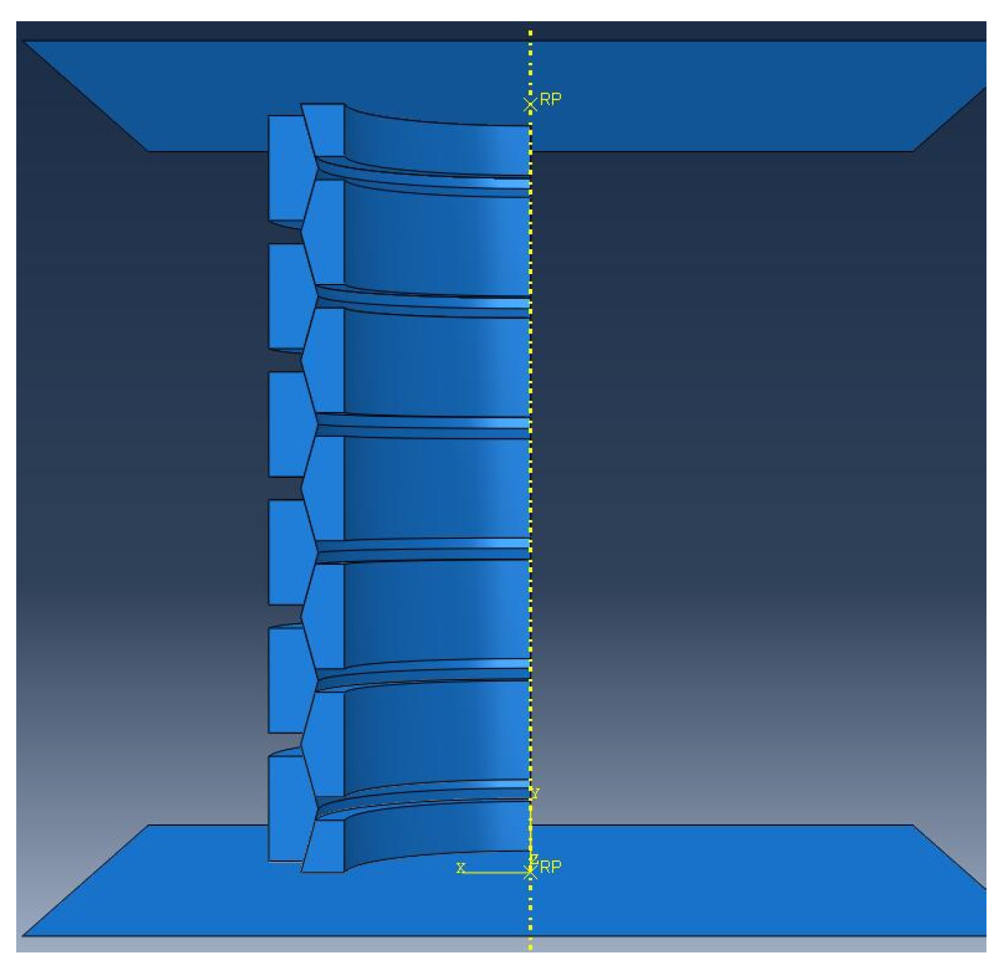
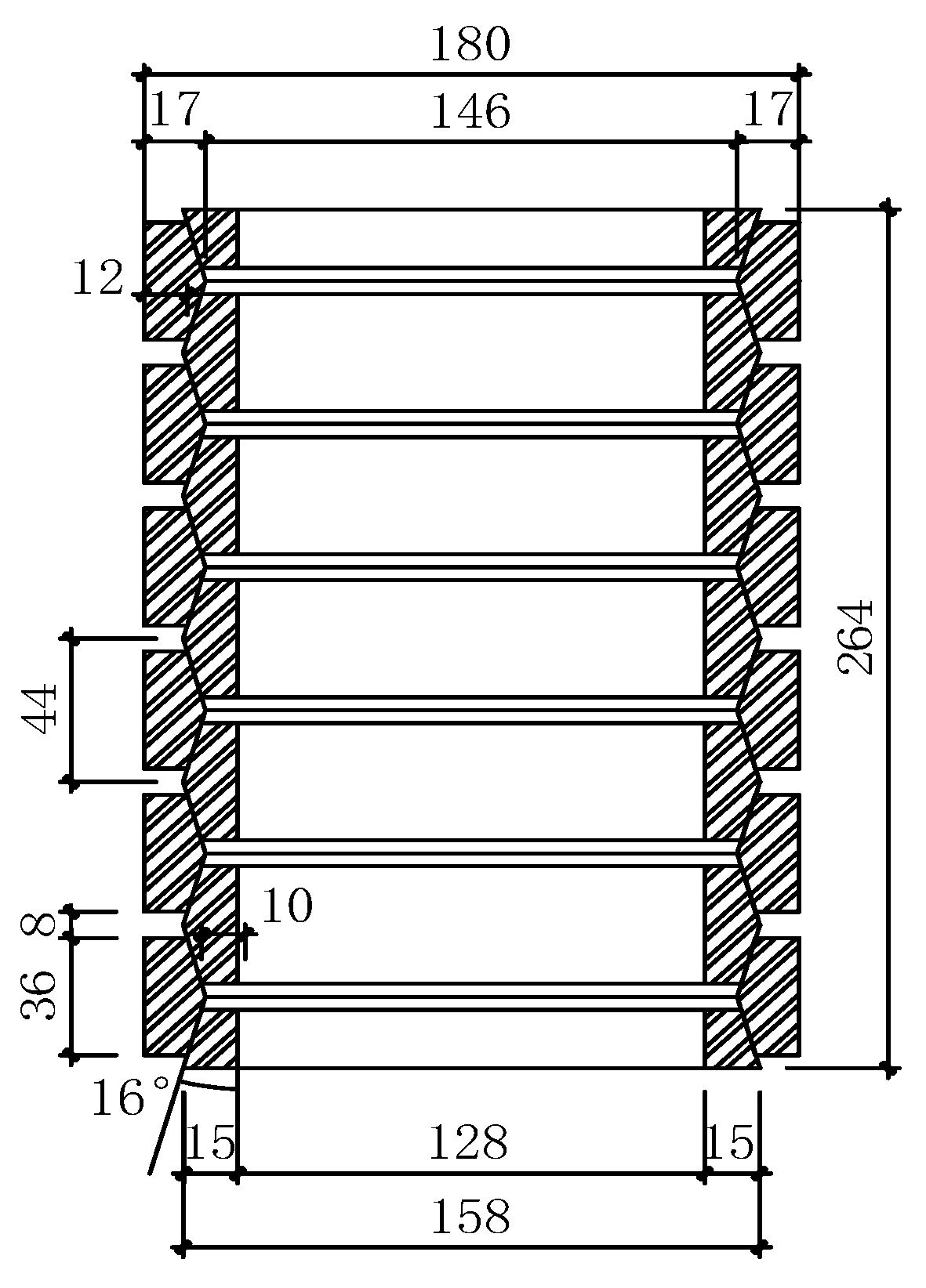
The finite element software ABAQUS was used to simulate the ring spring. It is more efficient to calculate the result by establishing only a quarter of the whole structure since the geometry, the boundary constraints, and the load of the ring spring are all axisymmetric structures [17,18,19]. The three-dimensional model is shown in Figure 3. As we can see, the spring and upper and lower connecting plates are all established. The spring compression is achieved by slowly controlling the displacement of the upper connecting plate. The ring spring includes six outer rings, five inner rings, and two half inner rings. The specific dimensions are shown in Figure 4.
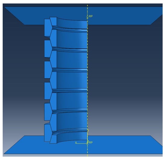
Figure 3.
Finite element model of ring spring.
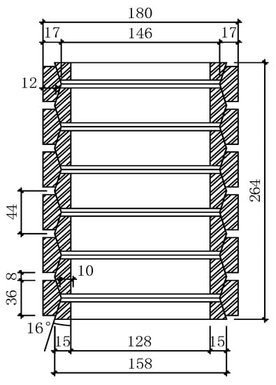
Figure 4.
Structure size of ring spring (unit: mm).
The material of the ring spring is 60SiMnA spring steel, of which the elastic modulus is 2.06 × 10⁵ N/mm2. The Poisson’s ratio is 0.3, and the density is 7.85 g/cm3. The ideal elastic–plastic model is adopted for the material relationship of the ring spring, and the yield stress is 1375 Mpa [20]. The ring spring is composed of C3D8I units, which introduces an additional degree of freedom to enhance the deformation gradient of the unit in the first-order unit. The additional degree of freedom enables the first-order element to produce a linear change in the element domain to overcome the problem of shear self-locking, and it only requires a few elements in the thickness direction, therefore saving on cost. When the element distortion is small, the results of displacement and stress are accurate. In summary, the C3D8I unit can effectively simulate the deformation and stress characteristics of the ring spring. The design of the connecting plate should ensure sufficient rigidity and strength to guarantee the correct transmission of the load. Therefore, the deformation of the upper and lower plates is ignored in the finite element simulation. The elastic modulus of the upper and lower plates is set to be much greater than the spring material during the analysis, so the rigid material is used to analyze the rigid surface for simulation.
When we define the contact property of the inner rings and the outer rings, the normal direction is hard contact while the penalty function method is selected for the tangential direction. We apply plane–plane contact with consideration of friction to each contact surface and establish contact pairs between the inner rings and the outer rings. The friction coefficient is 0.10 [21]. We apply symmetrical constraints on the symmetrical surface of the ring spring, and set UX = UR2 = UR3 = 0 on the X surface and U3 = UR1 = UR2 = 0 on the Z surface.
3. Results
3.1. Simulation Results
3.1.1. Mises Stress
When the spring is fully tightened, its height is 216 mm. At this time, the inner rings and the outer rings’ conical surfaces are completely in contact with each other. The entire spring is a solid structure whose stiffness is approaching infinity. At the same time, the meaning of the spring is lost. To avoid such a situation, the spring should keep the minimum spacing within a normal use limit, such as 1–3 mm. After calculation, the amount of spring deformation in the normal state can be 36 mm. The amount of deformation in the limit state of the spring can be 48 mm.
When compressing the ring spring to 36 mm and 48 mm, respectively, then unloading it completely, the stress contours (Figure 5) are obtained. Lastly, the simulation results are compared with the calculation results from the formula.

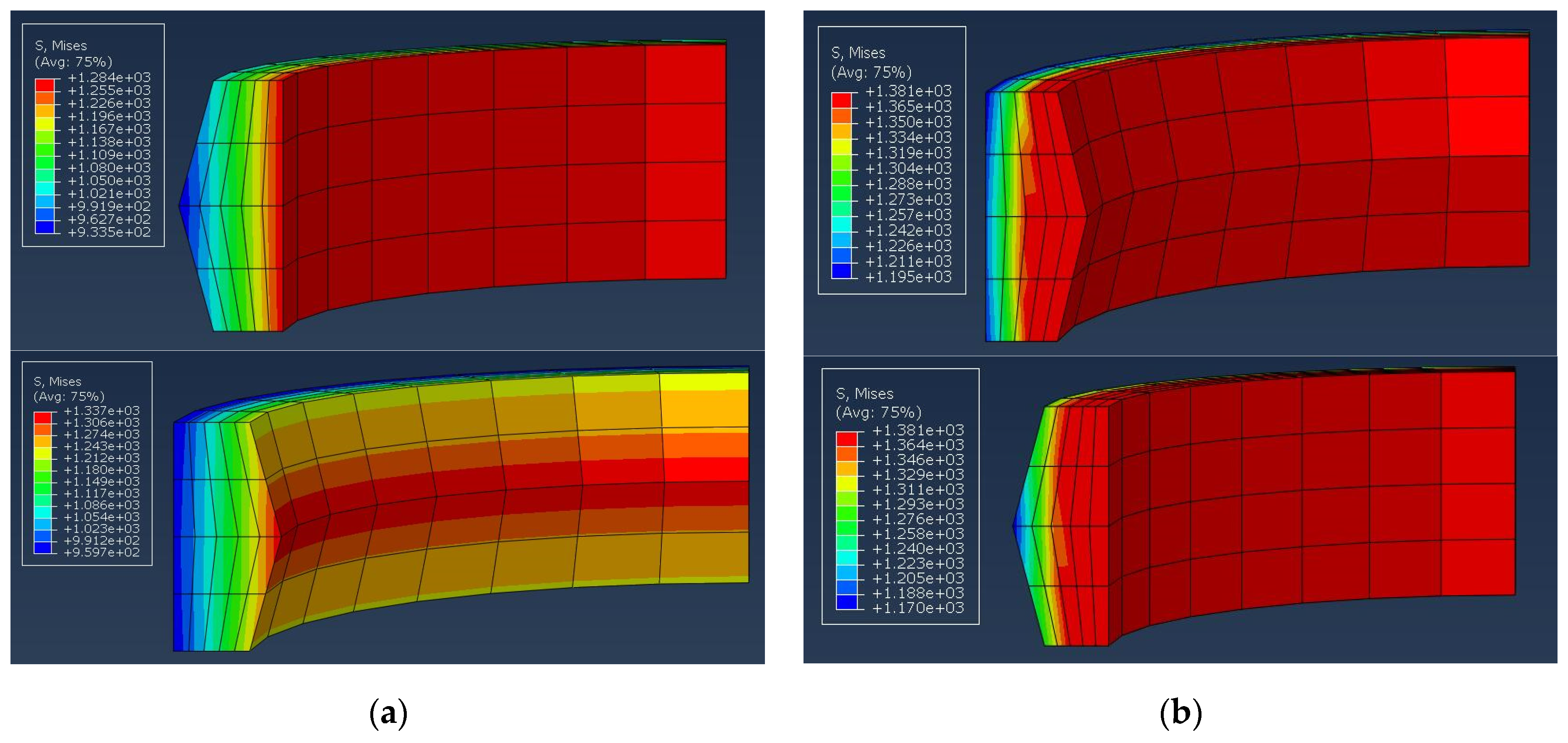
Figure 5.
Mises stress contour of finite element model for different capacity limits: (a) 36 mm; (b) 48 mm.
When the ring spring is at the normal service limit (36 mm), it can be seen from the stress cloud diagram that the stress changes uniformly with the diameter in the diameter direction. The stress of the inner rings and outer rings is gradually reduced as the rings’ diameter increases outward. The surface stress at the outer ring’s cone angle is the maximum stress of the ring spring, reaching 1340 MPa. The maximum stress of the ring spring is less than the ring spring’s yield stress, which is 1375 MPa, indicating that the spring is in an elastic deformation state under normal use limit. The stress change of the outer ring is 959.7 MPa to 1337 MPa, and the maximum stress appears at the cone angle. The stress change of the inner ring ranges from 933.5 MPa to 1284 MPa, and the maximum stress happens in the innermost section.
When the ring spring is at the limit of load capacity (48 mm), nearly half of the cross-sectional stress of the inner rings and the outer rings reaches the yield stress (Figure 5). The maximum stress reaches 1383 MPa, which is slightly greater than the yield stress of the ring spring. At the stress level of 1383 MPa, the spring undergoes slight plastic deformation. The stress change of the outer ring is 1195–1381 MPa. The stress change of the inner ring is 1170–1381 MPa.
3.1.2. Load–Displacement Curve
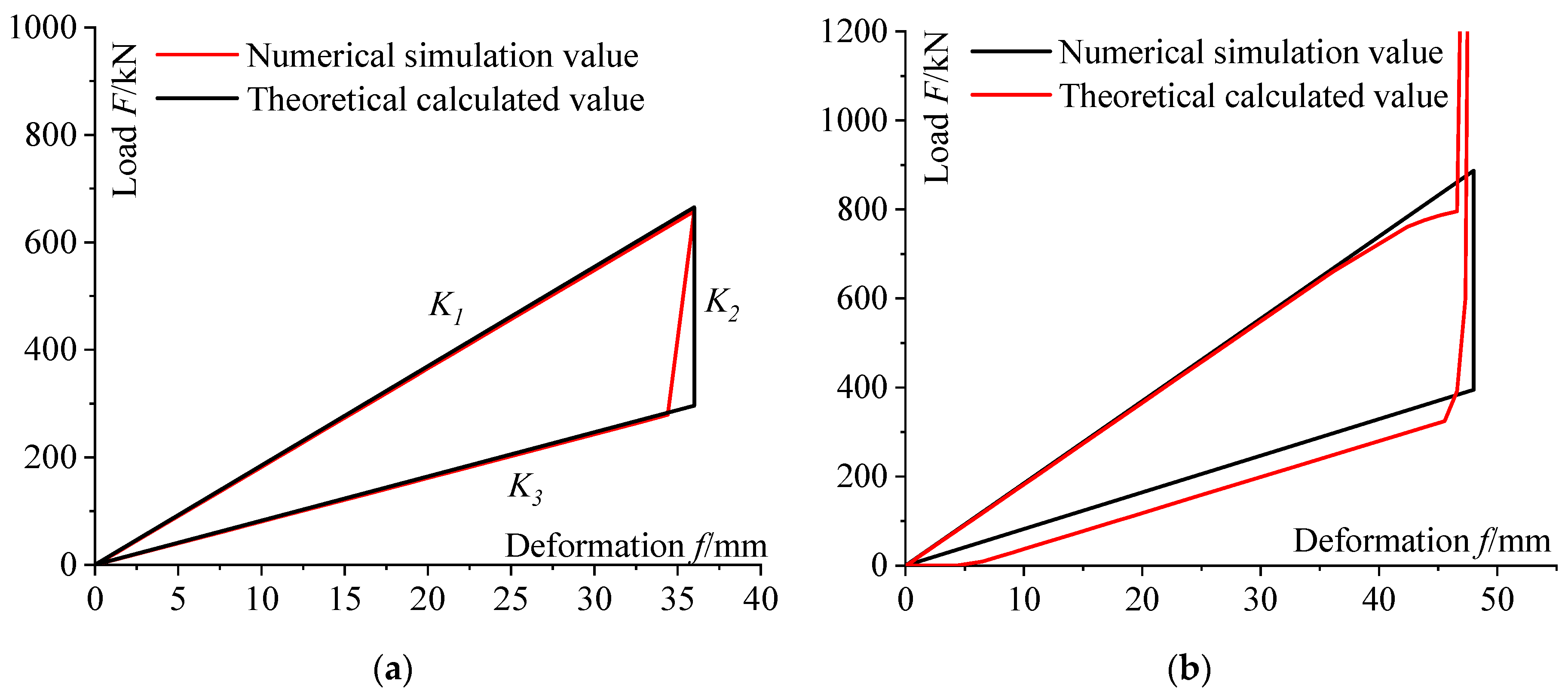
Normal use limit (36 mm): Figure 6a and Table 1 shows that the result of the numerical simulation is basically identical to that of the theoretical calculation. The unloading section of the characteristic curve obtained by the software has a hysteresis phenomenon. The characteristic curve obtained by the software is more consistent with the actual test results. Under normal loading and unloading cycles, the ring spring can be divided into three kinds of stiffness (loading stiffness K1, unloading stiffness K2 and unloading stiffness K3). At the displacement of about 1.4 mm when the spring just starts to unload, the unloading stiffness is K2 = 236.872 kN/mm.
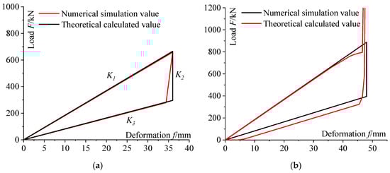
Figure 6.
Comparison of load–displacement curves between theoretical calculation and numerical simulation for different capacity limits: (a) 36 mm; (b) 48 mm.

Table 1.
Comparative analysis of theoretical calculation and numerical simulation.
Bearing capacity limit (48 mm): Figure 6b and Table 1 shows that the spring is in an elastic state when the spring is loaded. The software results are consistent with the theoretical results. After the spring is loaded to the normal service limit of 36 mm, the spring stiffness begins to decrease slowly. The spring stiffness rapidly increases as it approaches 48 mm. The final bearing capacity is 3147.296 kN. From the normal use limit to the loading capacity limit, the ring spring tightens gradually. The spring can be regarded as a hollow cylinder if the structural significance of the spring is lost. The large stiffness and bearing capacity help protect the spring and serve as a safety guarantee for the gravity of the superstructure. The spring shows a small amount of plastic deformation during the unloading process, which causes the unloading curves not to overlap. If the impact is not large, the spring can still work.
3.1.3. Hysteresis Curve
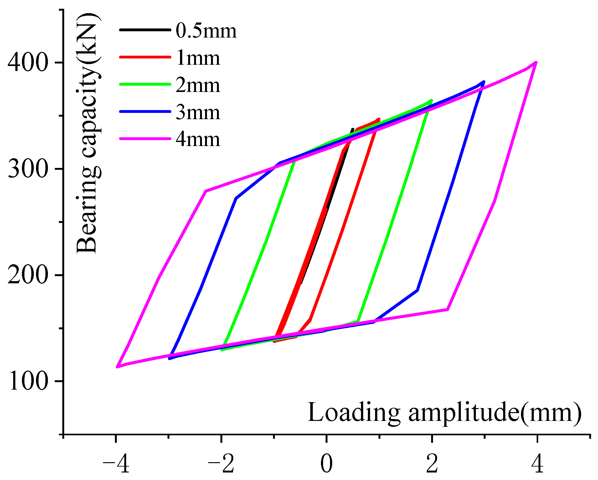
To explore the effect of the displacement amplitude on the spring mechanical properties, the ring spring was loaded with a preload displacement of 18 mm at a displacement frequency of 5 Hz with a continuously increasing displacement amplitude (0.5–1–2–3–4 mm). Each amplitude involved five sine loading cycles. It can be seen from the hysteresis curve (Figure 7) that the ring spring has good energy dissipation properties and stable dynamic performance.
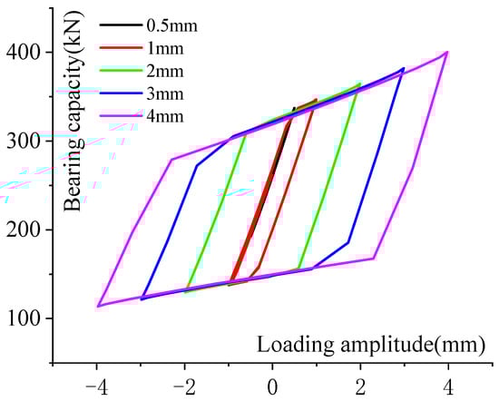
Figure 7.
Hysteretic curve when changing the loading amplitude.
Since the preload displacement of the ring spring is 18 mm, the area enclosed by the hysteresis curve is very small when the displacement amplitude is 0–0.7 mm (Figure 8a). Additionally, the load–displacement curve of the spring is straight, with a slope of approximately 145 kN/mm. When the displacement amplitude is greater than 0.7 mm, the hysteresis curve of the spring is a rhombus (Figure 8b), which becomes fuller as the displacement increases. The energy dissipation capacity of the ring spring also increases as the displacement amplitude increases.
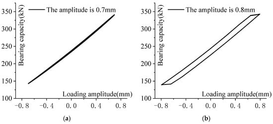
Figure 8.
Hysteresis curve of ring spring for different amplitudes: (a) 0.7 mm; (b) 0.8 mm.
3.2. Formula Verifications
We change the ratio of spring wall thickness to diameter so that four sets of thin-walled ring spring and four sets of thick-walled ring spring are provided in Table 2. The annular stress contour of the outer rings and the numerical comparison are as follows (Figure 9).
Table 2.
Setting of working conditions for changing wall thickness/diameter (unit: mm).
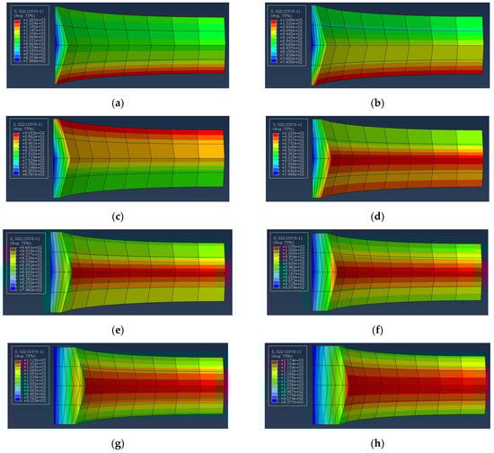
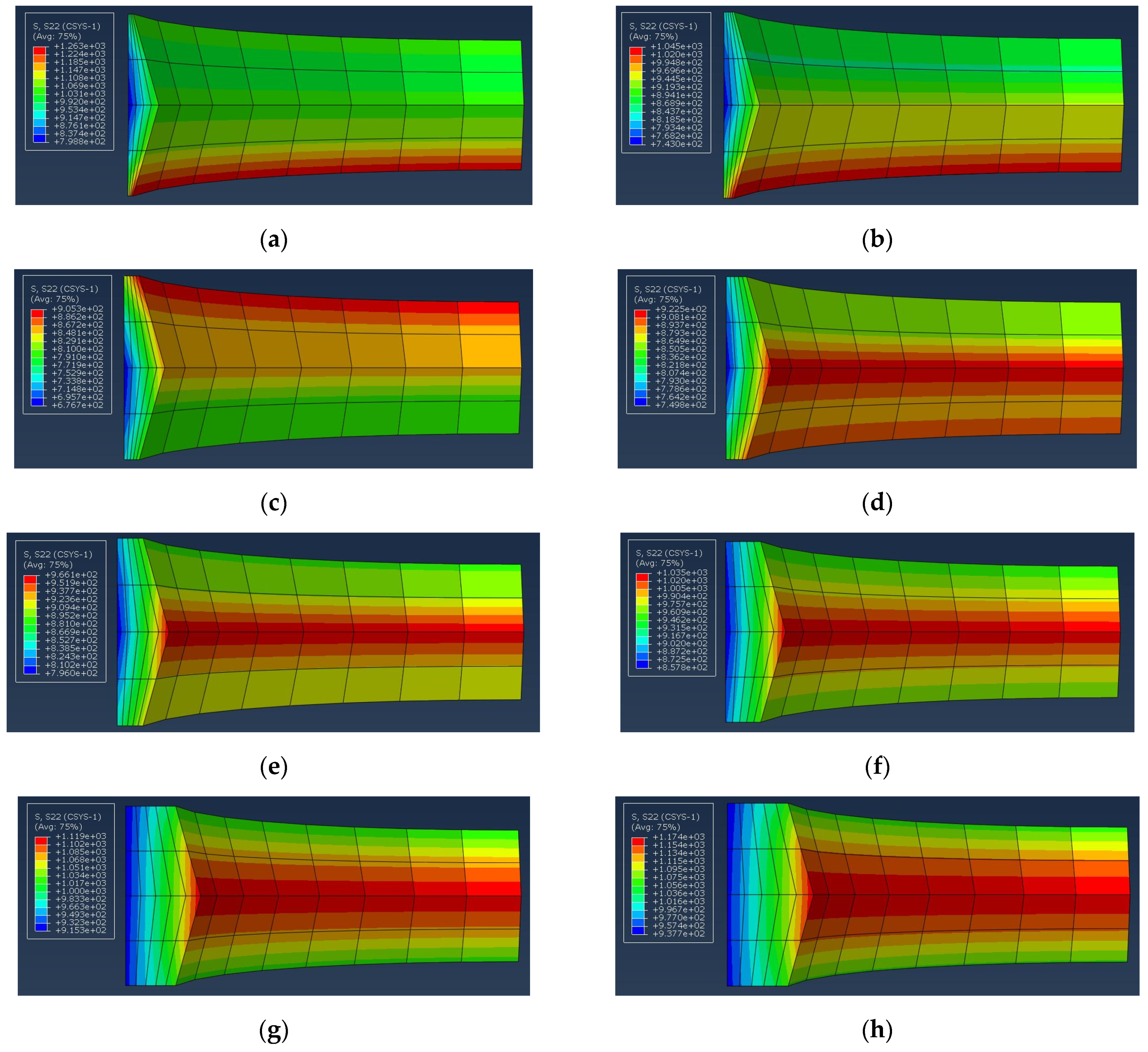
Figure 9.
Annular stress contour with varying wall thickness: (a) group 1; (b) group 2; (c) group 3; (d) group 4; (e) group 5; (f) group 6; (g) group 7; (h) group 8.
From the stress contour, it can be seen that the distribution of circumferential stress of the thin-walled ring spring and the thick-walled ring spring is not the same. The maximum hoop tensile stress of the thin-walled ring spring is generated at the upper and lower edges of the contact surface, while the thick-walled type is produced at the cone angle. The maximum hoop compression stress of the thin-walled ring spring is generated at the upper and lower edges of the innermost side, while the thick-walled ring spring is generated at the innermost side. The hoop stress of the ring spring increases as the ratio of thickness to diameter increases. However, when the ratio is very small to a certain degree (1/30), the spring is prone to producing stress concentration problems. Then, the hoop stress increases.
By comparing the theoretical formula of the spring manual with the supplementary formula proposed in this paper and the numerical simulation value obtained by the finite element software, we found that as the ratio of thickness to diameter decreases, the theoretical formula is more accurate (except for the first group of models) according to Table 3. The results meet with derivation’s premises and assumptions of the theoretical formula. The theoretical formula derivation applied to the thick-walled ring spring has an aberration of more than 20 percent. Such a high rate of aberration shows that the theoretical formula does not apply to the thick-walled ring spring. The aberration of the supplementary formula for the maximum hoop tensile stress of the thick-walled ring spring proposed in this paper is within 8%. As the ratio of thickness to diameter increases, the theoretical formula derivation gives a more accurate result. The accuracy asserts the correctness of this supplementary formula.
Table 3.
Comparative analysis of the maximum tensile stress of the outer ring by theoretical calculation and numerical simulation.
3.3. The Design of Vibration Isolator
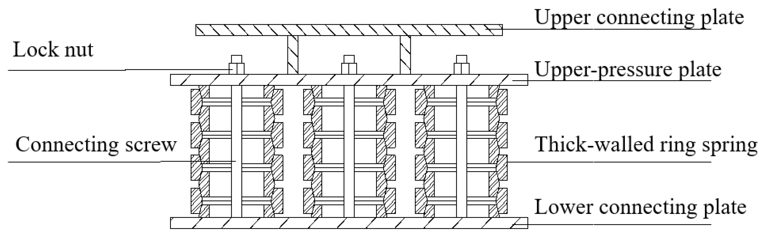
This paper proposes a new ring spring vibration isolator (Figure 10) which mainly includes the upper and lower connecting plates, upper pressure plates, connecting screws, lock nuts, and thick-walled ring springs.
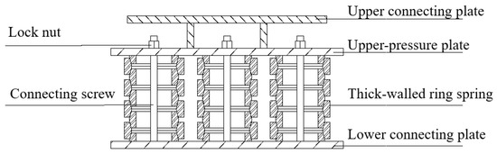
Figure 10.
Schematic diagram of the structure of a new ring spring isolator.
(1) Upper and lower connecting plates are composed of steel plates, where several bolt holes are found. Through the holes, these plates are connected to the column and the foundation by high-strength bolts.
(2) As for the upper pressure plate, there must be enough spring compression moving space between the upper pressure plate and the upper connecting plate.
(3) The connection screw is set between the upper pressure plate and the lower connection plate, and it is movable between the two plates. When the spring is under pressure, the vertical load is transmitted to the upper pressure plate through the upper connecting plate. Then, the upper pressure plate compresses the spring and the screw stays still. When the spring is under the tension, the lock nut set on the screw limits the displacement of the spring and prevents its structure from being damaged by the tension. The spring can also be preloaded by connecting the screw and the lock nut.
(4) A thick-walled ring spring is located between the upper pressure plate and the lower connecting plate. It is composed of several outer rings, several inner rings, and two halves of inner rings. The wall thickness of the ring is 1/10 to 1/20 of the diameter. A rubber film can be placed between the spring and the steel plate to reduce metal wear. The spring isolator can be made up of several thick-walled same-sized spring groups in parallel.
To meet the requirements of both space constraints and bearing capacity, we can install more than one new ring spring isolator under the column. The barycenter of the new ring spring isolator coincides with the barycenter of the column, so the load of the superstructure can be better transmitted to the vibration isolator.
4. Analysis of Vibration Isolation Structure
4.1. Model Parameters
Our research takes a typical six-story frame structure as an example (Figure 11), and uses software SAP2000 to model the common structure and vibration isolation structure. The building plane is distributed in a rectangular shape. A single secondary beam is set between the main beams in the Y direction. The basic layout of the building is five spans, which are six meters in the X direction, and three spans, which are four meters in the Y direction. The structure has six floors, and each floor is 3.6 m high. The concrete strength grade is C30. The steel bars are HRB400 and HRB335. The section size of the frame column, the frame beam and the secondary beam is 600 mm × 600 mm, 300 mm × 600 mm and 300 mm × 500 mm, respectively. The thickness of the slab is 110 mm. The self-weight of the structure and the uniformly arranged constant load of the floor are set as 3 kN/m2. The live load of the floor is set as 2 kN/m2.
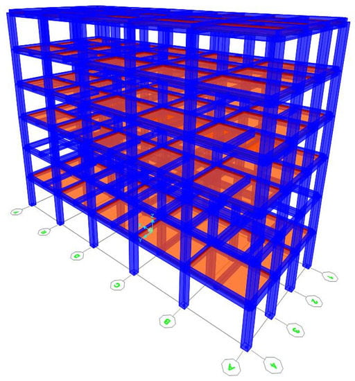
Figure 11.
Schematic diagram of the three-dimensional structure model.
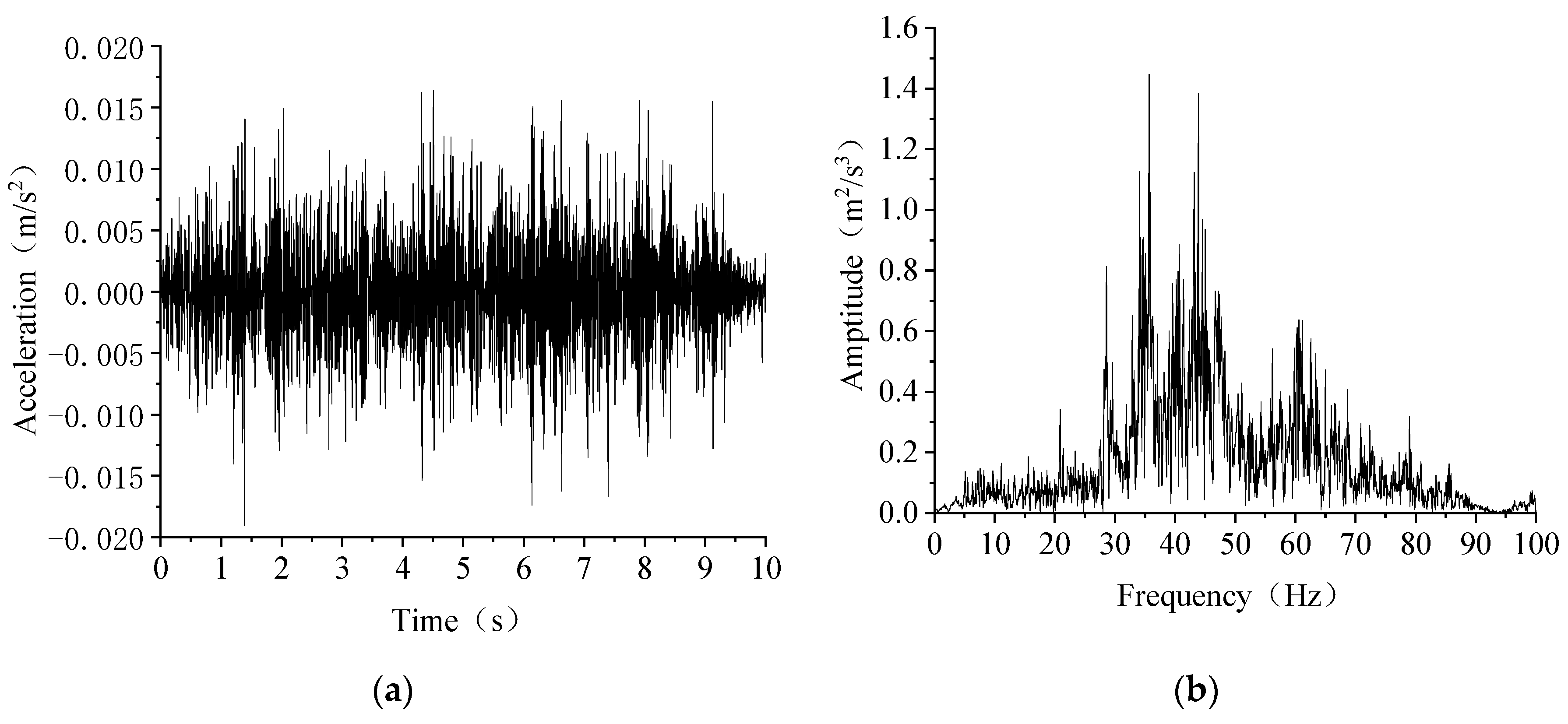
For the metro vibration simulation of buildings, the most commonly used direct method is to input the vertical acceleration at the bottom of the building. Ling et al. [22] at South China University established a building model and compared simulation data with the measured data. The parameter analysis verified the correctness of the model, so it is desirable to input the measured vibration acceleration excitation in the base. Since the focus of this paper is to establish a comparison between ordinary structures and vibration isolation structures to explore the vibration isolation effect of vibration isolators instead of accurately assessing the actual vibration level of the building, the interactions between soil and structure are not considered. The ten-second measured vibration acceleration of the free field is directly input in the building base (Figure 12).
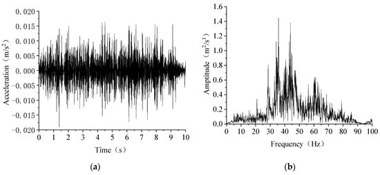
Figure 12.
Vertical acceleration curve: (a) time history; (b) spectra.
From the spectra curve of the metro vibration, the energy of metro vibration is shown to be mainly concentrated in the range of 20 Hz to 50 Hz, which is consistent with the research results [23]. In order to cover the main frequency band 30 Hz to 50 Hz in the analysis and to consider the low-order vibration mode of the building, the two frequency points of 1 Hz and 50 Hz are used to determine these two coefficients. Therefore, the damping coefficient is: α = 0.3696 Hz, β = 1.872 × 10⁻⁴ s.
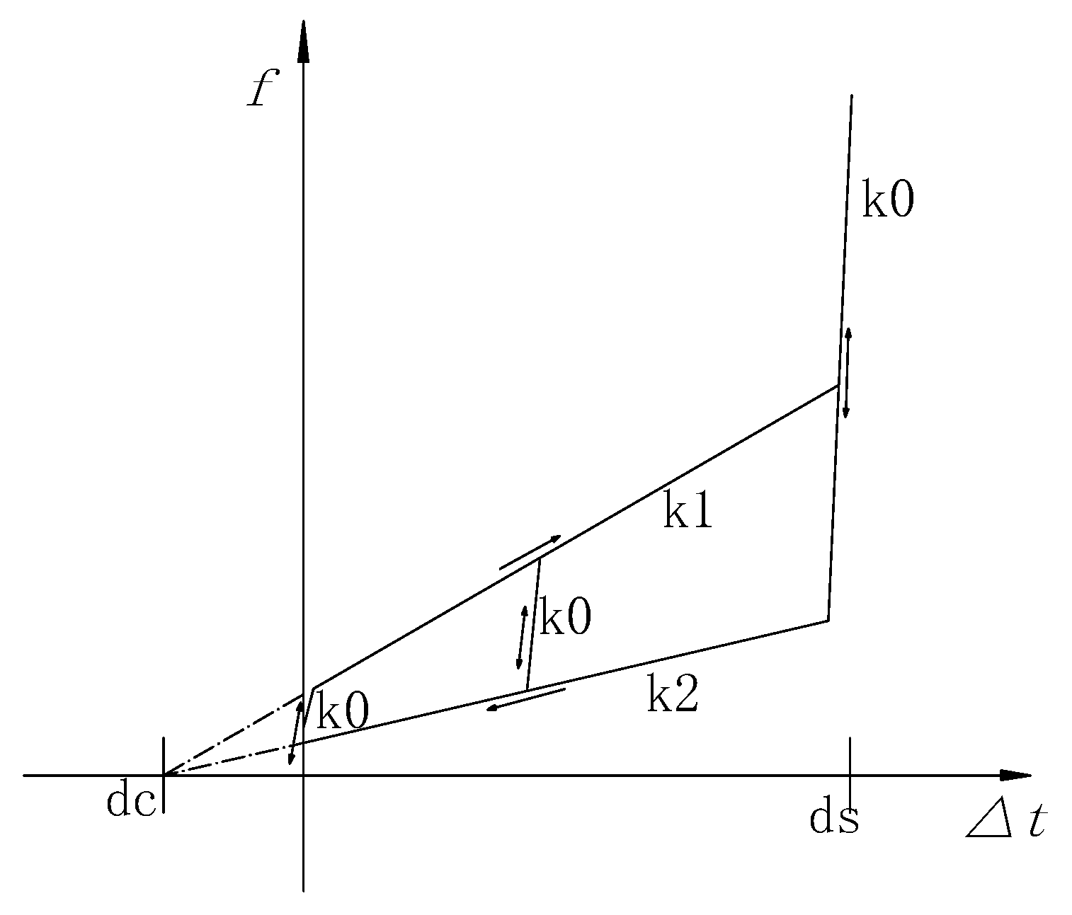
Considering that vibration caused by the metro is microvibration and the structure is in the elastic state, the elastic material model has been used in the entire finite element analysis. The beam–column element is simulated by the frame element. The floor element is the shell element. Under slight vibration, the damping ratio of concrete can be taken as 0.03 [24]. In addition to its simplicity, the Rayleigh damping structure also satisfies orthogonal conditions. SAP2000 has developed the “Damping-Friction Spring” unit for the widespread application of friction springs at this stage. Its damping model is based on the viscoelastic model of Maxwell, and its nonlinear force–deformation relationship is [25]:
where is the unit force, c (t) is the controllable damping constant (positive) and is the damper deformation. As is shown in Formula (6), the unit dissipates energy based on displacement (independent of speed) [26], which is specifically manifested as internal friction related to the deformation during loading and unloading. The nonlinear force–deformation relationship is shown in Figure 13.

Figure 13.
Force–deformation curve of friction spring damper.
The stiffness K1 of loading is greater than the stiffness K2 of unloading. Due to the change in the direction of the frictional force, the transition between K1 and K2 is made by a great elastic stiffness K0. In addition, the sliding limit can be defined by setting the end displacement ds, and the stiffness K0 is used for deformations exceeding ds. By setting the preload displacement dc, the initial force required to start sliding during loading and to terminate sliding during unloading can be defined. The “friction spring damper” unit can accurately simulate the setting of the ring spring vibration isolator, so the friction spring unit is used for simulation.
Under the standard conditions of extracting gravity load, the vertical reaction force at the bottom of the common structure column is about 1470 kN and five identical sets of ring springs can be used as a base vibration isolator simultaneously, arranged between the column and the foundation. The vertical section of the vibration isolation connection with the column bottom is shown in Figure 14.
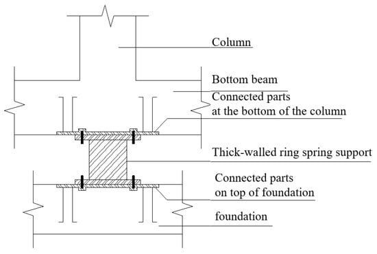
Figure 14.
Vertical section schematic diagram of the vibration isolation connection at the column bottom.
In the software simulation, the focus is only on the vertical performance of the vibration isolation system, so the horizontal nature of the spring isolator is set to fixed. Eight isolators are arranged at the bottom of the columns of the C and D axis of the middle two frames where the vertical vibration response is relatively unfavorable. Additionally, the relevant mechanical combination parameters are listed in Table 4.
Table 4.
New ring spring isolator parameters.
4.2. Vibration Response
4.2.1. Modal Analysis
The modal analysis of the common structure and the vibration isolation structure is carried out to obtain the values of the vertical natural vibration frequency and horizontal natural vibration frequency of the structure (Table 5). It can be seen from Table 5 that eight vibration isolators are arranged to change the vertical frequency of the overall structure, making the first vertical frequency smaller. The effects on the horizontal frequency can be negligible. For the vibration isolation structure, the first-order vertical frequency is significantly reduced after vibration isolation because the stiffness of the vibration isolator layer is smaller than the rigidity of the superstructure. The vibration mode appears as the overall motion of the vibration isolator superstructure. If vibration isolators are installed under all columns at the same time, the vertical natural vibration frequency of the structure will become smaller and further from the excellent frequency of metro vibration waves. Thus, the ring spring vibration isolator is able to extend the natural vibration period of the structure effectively and reduce the transmission of vertical vibration to the superstructure.
Table 5.
Structure natural frequency (unit: Hz).
4.2.2. Comparison between Acceleration and Frequency
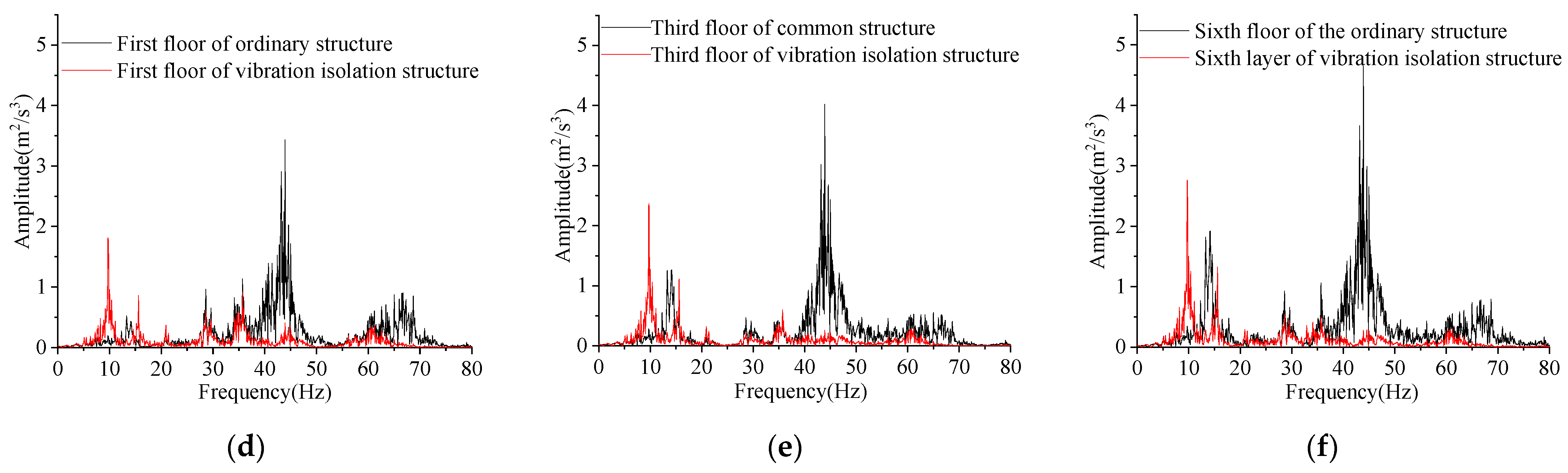
Under the action of the measured ground vertical acceleration caused by the operation of the metro, the same position of the ordinary structure and the vibration isolation structure is selected as the observation point. The vertical acceleration response value of the column above the vibration isolator is extracted for analysis. For brevity, we just select the vertical acceleration and spectra curve of the first, third and sixth floor (Figure 15). The conclusions are drawn as follows:
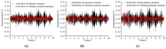
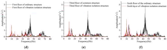
Figure 15.
Structural vibration response: (a) vertical acceleration of the first floor; (b) vertical acceleration of the third floor; (c) vertical acceleration of the sixth floor; (d) spectra of the first floor; (e) spectra of the third floor; (f) spectra of the sixth floor.
(1) Under the excitation of metro vibration, the vertical acceleration amplitude is about 30 mm/s2. The propagation of vibration on the floor is wavy, which increases first and then decreases and then increases. The acceleration of the top layer is the maximum. The main frequency of vibration is 30 Hz to 50 Hz, which is the same as the input vibration acceleration.
(2) Under the excitation of metro vibration, the vertical acceleration amplitude of the vibration isolation structure is about 15 mm/s2. The propagation of vibration on the floor is a translational type, and the amplitude is basically unchanged. The main frequency of vibration is 5 Hz to 15 Hz.
(3) After the ring spring vibration isolator is installed, the vertical acceleration of the structure is significantly reduced by about 50%. The main frequency of the structure vibration is reduced, and the vibration of the 30 Hz to 50 Hz component is filtered. At the same time, the vibration of the resonance frequency part is amplified (5 Hz to 15 Hz). The ring spring vibration isolator can play a role in vertical vibration isolation, effectively improving the comfort of the structure.
4.3. Vibration Isolation Ratio
We define the vibration isolation rate φ as Equation (6). The larger the value φ is, the better the vibration isolation effect is. We extract the peak acceleration values of each layer and compare them as shown in Table 6.
Table 6.
Acceleration peak and vibration isolation ratio of the structure.
After the vibration isolator is installed, the structure’s peak acceleration of each floor is reduced. The maximum vibration isolation rate is 60.53% and the average vibration isolation rate is 37.72%. The overall vibration trend of the vibration isolation structure is gentle.
where is the vertical acceleration peak value of the ordinary structure; is the vertical acceleration peak value of the vibration isolation structure; and the unit is mm/s2.
4.4. Stiffness and Displacement
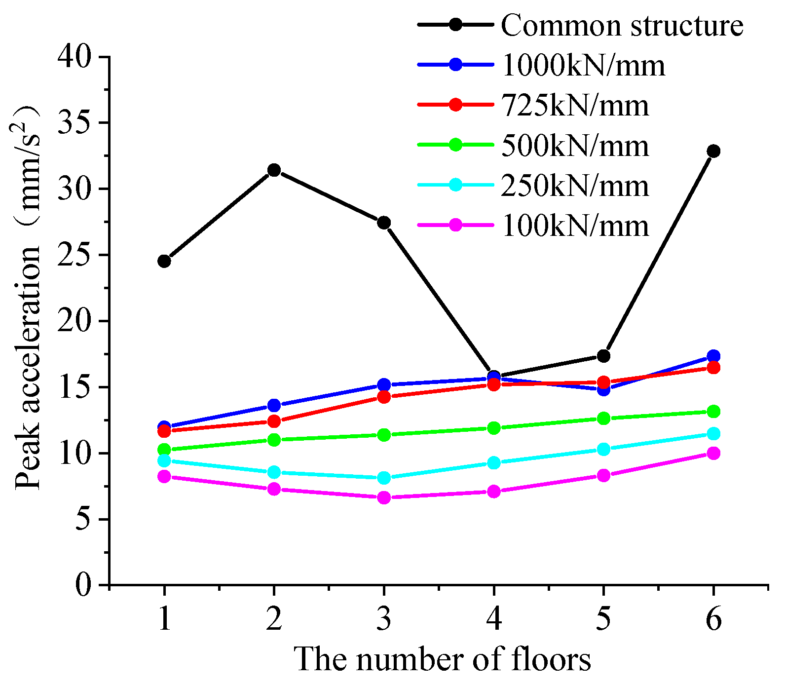
The value of the vertical equivalent stiffness parameter of the isolator is changed to explore the effect of the vertical stiffness of the ring spring vibration isolator on the vibration isolation effect. The four vertical directions of 100 kN/mm, 250 kN/mm, 500 kN/mm and 1000 kN/mm are supplemented to obtain the peak acceleration of the vertical vibration of the structure (Figure 16). It can be seen that the vertical equivalent stiffness of the ring spring vibration isolator varies from 100 kN/mm to 1000 kN/mm. The isolator can still play the role of isolating metro vibration. Although the normal use of the superstructure will be affected when the vertical deformation is greater, smaller equivalent stiffness still leads to a better vibration isolation effect.
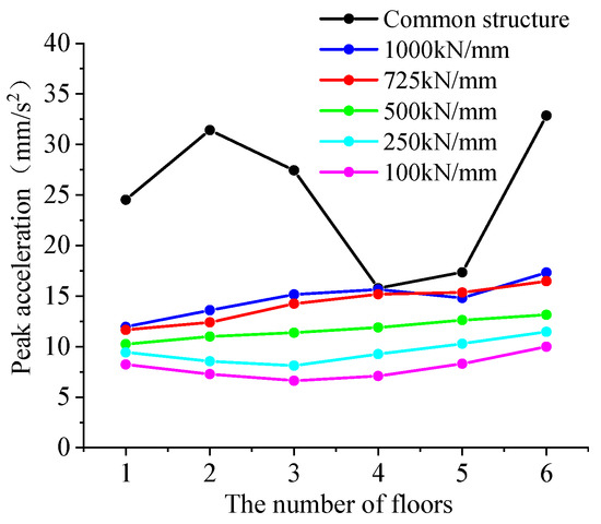
Figure 16.
Peak acceleration as the stiffness changes.
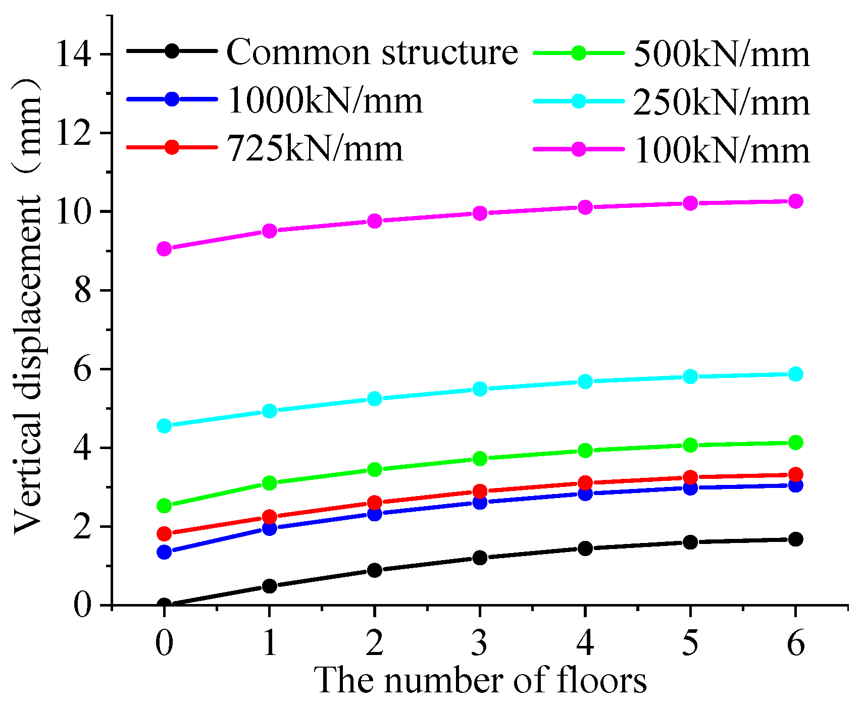
We choose the absolute peak displacement of the column bottom node of the vibration isolation structure, and verify whether it is within the effective working range of the ring spring. As shown in Figure 17, it is the vertical displacement of the isolation system.
Figure 17.
Vertical displacement as the stiffness changes.
When the stiffness changes from 100 kN/mm to 1000 kN/mm, the displacement is always within the effective working range. As the equivalent stiffness decreases, the vertical displacement also increases disproportionately. The displacement is mainly concentrated on the vibration isolator. The displacement of each floor is in overall translation. In terms of the vibration isolation effect and vertical deformation, the vertical stiffness of the ring spring vibration isolator is 500–1000 kN/ mm.
5. Conclusions
In this study, theoretical derivation and numerical simulation are carried out to study the mechanical characteristics of a ring spring. The original formula (Equations (1) and (2)) only applies to thin-walled ring springs, the bearing capacity of which is relatively weak. Hence, a new formula suitable for thick-walled ring springs has been put forward. Then, a novel ring spring isolator was designed for vibration isolation of metro superstructures. The following conclusions can be drawn:
(1) Through the comparison of theoretical calculation and finite element simulation, the error of the supplementary formula of the maximum hoop tensile stress for thick-walled ring springs is within 8%, and it becomes more accurate with the increase in the ratio of thickness to diameter.
(2) From the simulation results of the thick-walled ring spring, the stress of the thick-walled ring spring changes simultaneously along the direction of the diameter. The maximum stress of the outer ring occurs at the cone angle whereas the maximum stress of the inner ring occurs on the innermost section. The energy dissipation capacity of the ring spring increases along with the increase in the loading amplitude.
(3) A ring spring is a kind of vibration damping device widely used in the field of mechanical engineering. In this study, an innovative application of ring springs is used to design vibration isolators for metro superstructures.
(4) By comparing the dynamic response of isolated structures and non-isolated structures, it is found that the isolator significantly reduces the vertical acceleration of the structure. The amplitude of vertical acceleration is reduced by 50% while the vibration isolation rate is up to 60.53%. The average vibration isolation rate is 37.73%. The isolator changes the main frequency of vibration, which greatly reduces the vibration frequency by 30 Hz to 50 Hz.
6. Patents
Utility model patent: A ring spring isolator for vibration isolation [27].
Patent application number: 202020660008.1.
Patent licensing announcement number: CN 212613051 U.
Author Contributions
Methodology, Y.L.; software and writing, S.W. and J.G.; resources, supervision and revision, H.L. All authors have read and agreed to the published version of the manuscript.
Funding
The authors would like to gratefully acknowledge the support from the National Natural Science Foundation of China (Project No. 12172135). The work presented in this paper was also supported by grants received from the State Key Laboratory of Subtropical Building Science (No. 2019ZB25).
Institutional Review Board Statement
Not applicable.
Informed Consent Statement
Not applicable.
Data Availability Statement
Not applicable.
Acknowledgments
Y.L. thanks the State Key Laboratory of Subtropical Building Science (No. 2019ZB25) and the National Natural Science Foundation of China (Project No. 12172135) for financial support. We also thank Xuanwu Shu from Architectural Design and Research Institute of SCUT for technical support.
Conflicts of Interest
The authors declare that they have no conflict of interest.
Appendix A
Derivation of Equation (3):

Figure A1.
Ring spring force diagram.
Figure A1.
Ring spring force diagram.
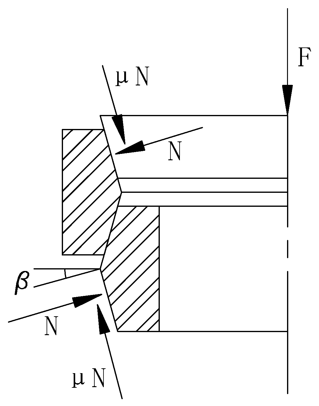
The radial force p2 of unit length on the center circumference of the outer ring section is:
Under the action of radial force, the cross-section of the outer ring is stretched, and the tension is F2. The radial force on the infinitesimal circle ds is p2ds, and its projection on the y axis is:
Therefore, the equilibrium equation of F2 is:
Assuming that the circumferential stress is uniformly distributed on the section, the tensile stress in the outer ring section is:
Additionally, positive pressure on the conical surface of the outer ring is:
Equation (A7) is substituted into Equation (A6) to obtain:
where D02 is the center diameter of the outer ring. The tensile stress of the outer ring under the action of circumferential force is Formula (A8). This part assumes that the circumferential stress is uniformly distributed on the section, so the center diameter of the ring section is calculated.
The compressive stress of the conical contact surface is:
For a thick-walled ring spring, the material stretches along the load direction, and the deformation is shortened in the direction perpendicular to the load. Therefore, the tensile stress in the circumferential direction of the inner surface caused by the compressive stress of the conical contact surface is:
where l is the width of the contact surface: ; is the distance between the two outer rings (or inner rings) adjacent to the ring spring, the limit position spacing of which is 1–3 mm during normal use.
References
- Abate, G.; Corsico, S.; Grasso, S.; Massimino, M.R.; Pulejo, A. Analysis of the vibrations induced by a TBM to refine soil profile during tunneling: The Catania case history. In Proceedings of the 45th ITA-AITES General Assembly and World Tunnel Congress, Naples, Italy, 3–9 May 2019. [Google Scholar] [CrossRef]
- Chao, Z.; Wang, Y.; Moore, J.A.; Sanayei, M. Train-induced field vibration measurements of ground and over-track buildings. Sci. Total Environ. 2016, 575, 1339–1351. [Google Scholar] [CrossRef]
- Chao, Z.; Wang, Y.; Peng, W.; Guo, J. Measurement of ground and nearby building vibration and noise induced by trains in a metro depot. Sci. Total Environ. 2015, 536, 761–773. [Google Scholar] [CrossRef]
- Zou, C.; Moore, J.A.; Sanayei, M.; Wang, Y. Impedance model for estimating train-induced building vibrations. Eng. Struct. 2018, 172, 739–750. [Google Scholar] [CrossRef]
- Ohsaki, M.; Miyamura, T.; Kohiyama, M.; Yamashita, T.; Yamamoto, M.; Nakamura, N. Finite-element analysis of laminated rubber bearing of building frame under seismic excitation. Earthq. Eng. Struct. Dyn. 2015, 44, 1881–1898. [Google Scholar] [CrossRef]
- Pan, P.; Shen, S.; Shen, Z.; Gong, R. Experimental investigation on the effectiveness of laminated rubber bearings to isolate metro generated vibration. Measurement 2018, 122, 554–562. [Google Scholar] [CrossRef]
- Ozdemir, G. Lead core heating in lead rubber bearings subjected to bidirectional ground motion excitations in various soil types. Earthq. Eng. Struct. Dyn. 2014, 43, 267–285. [Google Scholar] [CrossRef]
- Zhang, Y.H.; Hang, L.H.; Wang, D.C. Spring Manual; Mechanical Industry Press: Beijing, China, 2017; ISBN 978-71-1155-625-1. [Google Scholar]
- Law, M.; Wabner, M.; Kolouch, M.; Noack, S.; Colditz, A. Active vibration isolation of machine tools using an electro-hydraulic actuator. CIRP J. Manuf. Sci. Technol. 2015, 10, 36–48. [Google Scholar] [CrossRef]
- Sun, W.; Thompson, D.; Zhou, J. A mechanism for overcoming the effects of the internal resonances of coil springs on vibration transmissibility. J. Sound Vib. 2019, 471, 115145. [Google Scholar] [CrossRef]
- Sigaeva, T.; Kolesnikov, A.; Sudak, L. Deformation of a closed hyperelastic helical spring. Int. J. Non-Linear Mech. 2019, 110, 1–8. [Google Scholar] [CrossRef]
- Spaggiari, A.; Mammano, G.S.; Dragoni, E. Analytical design of superelastic ring springs for high energy dissipation. Mater. Sci. Forum 2018, 941, 1457–1462. [Google Scholar] [CrossRef] [Green Version]
- Fang, C.; Wang, W.; James, R.; Yang, X.; Zhong, Q.; Richard, S.; Chen, Y. Application of an innovative SMA Ring Spring System for self-centering steel frames subject to seismic conditions. J. Struct. Eng. 2018, 144, 04018114. [Google Scholar] [CrossRef]
- Issa, A.S.; Alam, M.S. Seismic performance of a novel single and double spring-based piston bracing. J. Struct. Eng. 2019, 145, 04018261. [Google Scholar] [CrossRef]
- Golzar, F.G.; Rodgers, G.W.; Chase, J.G. Nonlinear spectral design analysis of a structure for hybrid self-centring device enabled structures. Struct. Eng. Mech. 2017, 61, 701–709. [Google Scholar] [CrossRef]
- Wang, C.; Yang, L.; Wang, S. Simulation analysis of friction and wear of new TiAl based alloy joint bearings. In Proceedings of the 3rd International Conference on Mechatronics Engineering and Information Technology (ICMEIT 2019), Dalian, China, 29–30 March 2019. [Google Scholar] [CrossRef] [Green Version]
- Chen, B.; Shen, L.; Zhang, H. Gaussian process regression-based material model for stochastic structural analysis. ASCE-ASME J. Risk Uncertain. Eng. Syst. Part A Civ. Eng. 2021, 7, 04021025. [Google Scholar] [CrossRef]
- Yang, Y.; Chen, B.; Su, Y.; Chen, Q.; Wang, H. Concrete mix design for completely recycled fine aggregate by modified packing density method. Materials 2020, 13, 3535. [Google Scholar] [CrossRef] [PubMed]
- Yang, Y.; Chen, B.; Zeng, W.; Li, Y.; Chen, Y. Utilization of completely recycled fine aggregate for preparation of lightweight concrete partition panels. Int. J. Concr. Struct. Mater. 2021, 15, 32. [Google Scholar] [CrossRef]
- Karr, U.; Sandaiji, Y.; Tanegashima, R.; Murakami, S.; Schnbauer, B.; Fitzka, M.; Mayer, H. Inclusion initiated fracture in spring steel under axial and torsion very high cycle fatigue loading at different load ratios. Int. J. Fatigue 2020, 134, 105525. [Google Scholar] [CrossRef]
- Wang, W.; Fang, C.; Zhao, Y.; Sause, R.; Hu, S.; Ricles, J. Self-centering friction spring dampers for seismic resilience. Earthq. Eng. Struct. Dyn. 2019, 48, 1045–1065. [Google Scholar] [CrossRef]
- Ling, Y.H.; Wu, S.; Gu, J.X.; Zheng, Z. A comparative study on vibration isolation methods of metro superstructure. J. South China Univ. Technol. Nat. Sci. Ed. 2021, 49, 1–8. [Google Scholar] [CrossRef]
- Ling, Y.; Gu, J.; Yang, T.Y.; Liu, R.; Huang, Y. Serviceability assessment of subway induced vibration of a frame structure using FEM. Struct. Eng. Mech. 2019, 71, 131–138. [Google Scholar] [CrossRef]
- Mohammed, H.J.; Zain, M.F.M. Experimental application of EPS concrete in the new prototype design of the concrete barrier. Constr. Build. Mater. 2016, 124, 312–342. [Google Scholar] [CrossRef]
- Inaudi, J.A. Modulated homogeneous friction: A semi-active damping strategy. Earthq. Eng. Struct. Dyn. 1997, 26, 361–376. [Google Scholar] [CrossRef]
- Weber, F.; Distl, J.; Meier, L.; Braun, C. Curved surface sliders with friction damping, linear viscous damping, bow tie friction damping, and semiactively controlled properties. Struct. Control Health Monit. 2018, 25, e2257. [Google Scholar] [CrossRef]
- Ling, Y.; Zhou, L.; Gu, J.; Ling, H. A Ring Spring Isolator for Vibration Isolation. China Patent CN 212613051 U, 26 February 2021. [Google Scholar]


Publisher’s Note: MDPI stays neutral with regard to jurisdictional claims in published maps and institutional affiliations. |
© 2021 by the authors. Licensee MDPI, Basel, Switzerland. This article is an open access article distributed under the terms and conditions of the Creative Commons Attribution (CC BY) license (https://creativecommons.org/licenses/by/4.0/).