Article

Model-Free Tracking Control with Prescribed Performance for a Shape Memory Alloy-Based Robotic Hand

Department of Mechanical Engineering and Automation, Northeastern University, Shenyang 110819, China
*
Author to whom correspondence should be addressed.
Appl. Sci. 2021, 11(19), 9040; https://doi.org/10.3390/app11199040
Submission received: 23 August 2021 / Revised: 16 September 2021 / Accepted: 24 September 2021 / Published: 28 September 2021
(This article belongs to the Section Robotics and Automation)

Abstract

:
The shape memory alloy (SMA)-based robotic hand has been a new emerging technology with potential applications ranging from life service to surgical treatment, because of the characteristics of SMA, such as high power-to-weight ratio, small volume and low driving voltage. However, due to the complex dynamic model and nonlinear aspects of SMA, it is complicated to control an SMA-based robotic hand. This paper presents a novel model free adaptive control for the SMA-based robotic hand system. By applying the Taylor series expansion method and the differential mean value theorem, the SMA based robotic hand system can be transformed into an equivalent linearization model, which merely depends on measurement data without any information on the system. Combined with prescribed performance control, the novel control method can constrain the tracking error in a preassigned domain. Experiments are conducted on the SMA-based robotic hand system to verify the performance of the presented control method.

1. Introduction

In recent years, developing service robots for human beings has been a prospective trend that has attracted the attention of scholars. As the main kind of service robotic system, the robotic hand has been extensively studied [1,2,3]. Robotic hands, conventionally composed of cumbersome mechanical components and rigid actuators, can produce accurate displacements and forces. However, conventional robotic hands are unsafe and exhibit poor adaptability when they interact with humans or the surrounding environment. With the development of smart materials, robotic hands have been actuated by different actuation techniques such as shape memory alloy (SMA) actuation [4,5,6], pneumatic actuation [6,7], and dielectric elastomer actuation [8,9]. Compared with other robotic hands, SMA-based robotic hands have shown dramatic potential for application because of the significant features of SMA, including a high power-to-weight ratio, low noise, and compact configuration [10]. Moreover, SMA can be easily actuated by a low driving electric current to achieve safe interactions between humans and robots. For these reasons, various prototypes of SMA-based hands have been proposed. Lee et al. developed an SMA-based robotic hand in [11], which was a lightweight and compact robotic hand that had all the SMA wires and returning springs embedded in the palm. Each finger has two degrees of freedom (DOF) and the thumb is completely passive. To ensure compactness and sufficient stroke, the SMA wires were wrapped around some pulleys. However, the structure of the proposed robotic hand is complex. Bundhoo et al. presented in [12] a four DOF biomimetic finger actuated by SMA wires arranged in an antagonist–protagonist configuration. In the paper, an abduction/adduction motion is added, and a passive compliance is introduced in the tendon’s cables by connecting a spring in series to each SMA wire and in parallel to a slack tendon wire. Each phalanx can perform a motion of 40 deg with a bending and stretching time of 25–30 s. A fingertip force of 0.4 N has been measured, while the grasping force is small. Maeno et al. developed in [13] a miniature five fingered hand designed for surgeries using 0.05 mm diameter SMA wires. This 20 DOF prototype shows a finger motion range of 30 deg. The measure fingertip force is 0.75 N. The motion range is small. In [14], a concept for an SMA-actuated gripper has been developed. In the structure, SMA wires are integrated in protagonist–antagonist muscle pair configurations. The maximum force is 1.4 N, which is small for the robotic hand, and the weight is large. In [15], an SMA-based robotic gripper is proposed for grasping. The gripper is composed of three fingers with variable stiffness. The maximum gripping force of the gripper is 6N. However, the production process needs a long time.
As the essential component of the SMA-based robotic hand, the robotic finger is designed by the SMA actuator embedded into a polymeric matrix [15,16]. The structure and the driving method of the SMA-based robotic finger are simple, whereas SMA has the characteristic of nonlinearity. The “shape memory effect” of SMA, between a low-temperature martensite phase and a high temperature austenite phase, can lead to the complexity and difficulty of controlling the robotic hand. The existing research focuses more on the method of controlling the SMA actuator, which can be separated including: (1) constructing models, for instance, mathematical models [17,18] and the “black box” model [19,20], to represent the SMA dynamics for further control; (2) designing a controller to improve the tracking ability of the SMA actuator, such as sliding mode control [21], PID [22] and fuzzy logic [23].
Generally, the SMA-based robotic hand can produce movements through the embedded SMA actuator [5,7,16], which can result in the complication of control. Moreover, the SMA-based robotic hand system is subjected to the parameter uncertainties and imprecise models [24,25]. Currently, two control methods are considered to improve the control precision of the SMA-based robotic hand system, namely, applying a neural network (NN) to establish the dynamic model of the robotic hand and designing a controller to reduce nonlinearities of the system. In [25], the neural network is used to model the SMA-based robotic hand system in real time, and then predictive control is used to predict the system so as to control the movement of the SMA hand. However, it takes a lot of time to collect the input and output data, and the model trained by the neural network also has errors. In [26], based on the step response signal, the transfer function of the SMA based robotic hand model is established by the system identification method. Then, the sliding mode control method is used to control the system. However, the SMA-based robotic hand is a nonlinear system, and there is a large error between the system identification model and the actual system. In [27], a fuzzy logic control method is designed to realize the motion control of the SMA-based robotic hand. The visual camera is used to track the position of the finger joint instead of the joint angle sensor, which reduces the complexity of the system. In [28], the motion of the SMA-based robotic hand is controlled by the fuzzy PID control method, in which fuzzy logic is used to adjust the parameters of PID. The experimental results show that the PID fuzzy controller has good performance in reducing the maximum overshoot and ensuring control stability. In addition, the control method based on SMA resistance feedback is also used in the control of the SMA-based robotic hand [29,30,31]. The key point of adopting NN methods is that the procedure is laborious for gaining the input/output (I/O) data for training the NN off-line. Moreover, it is uncertain that the training condition of building models is in accordance with the condition of the controlled plants in practise. The designing controller method is not taking the performance analysis or accuracy analysis into account. Therefore, it is imperative to design a controller with a simple structure and reliable performance for the SMA-based robotic hand, to obtain high tracking precision and ensure an advanced tracking performance.
For a practical system, a control method that is robust, with a simple structure and high precision is preferable. Hence, combined with a new dynamic linearization technique (DLT) derived from Deng [32], we propose a novel control method without the information of the controlled plant. The essence of DLT is that the discrete time nonlinear system can be substituted by an equivalent dynamical linearization data model, which is established at each dynamic execution time point of the closed-loop system. Furthermore, the dynamic linearization technique is a data-driven method, which is merely dependent on I/O data. In order to solve the disadvantages of conventional DLT, such as excessive parameters, the complications of parameter selection, and unclear physical significance for parameters, the new DLT is proposed by applying Taylor series expansion and the differential mean value theorem. It is generally known that it is inescapable to have to deal with the unmodeled dynamics and robustness problems. However, the new DLT can eliminate the above problems efficiently and effectively.
In recent years, prescribed performance control (PPC) has been a promising method for constraining the tracking error into a preassigned zone [33]. More specifically, the constrained tracking error can be converted into another form of unconstrained variable by a transformed error function. Then, PPC is designed to stabilize the unconstrained variable to further restrict the tracking error in a preassigned zone. For application, it is highly essential to investigate PPC for controlled plants, which are subjected to constraints generally, such as the steady state error and the convergence rate. Hence, PPC has been a research focus, attracting the interest of researchers [34,35,36].
Based on the above analysis, a model free control method with predefined accuracy is proposed for an SMA-based robotic hand system by using DLT and PPC to guarantee the tracking error constrained in a preassigned domain. The main contributions of this research are summarized in the following:
  • A novel model free control method combined with DLT and PPC is investigated for a class of discrete-time nonlinear systems to guarantee the tracking error in a preassigned boundary;
  • The condition, which cannot satisfy the continuity assumption, is considered to improve the applicability in the proposed method;
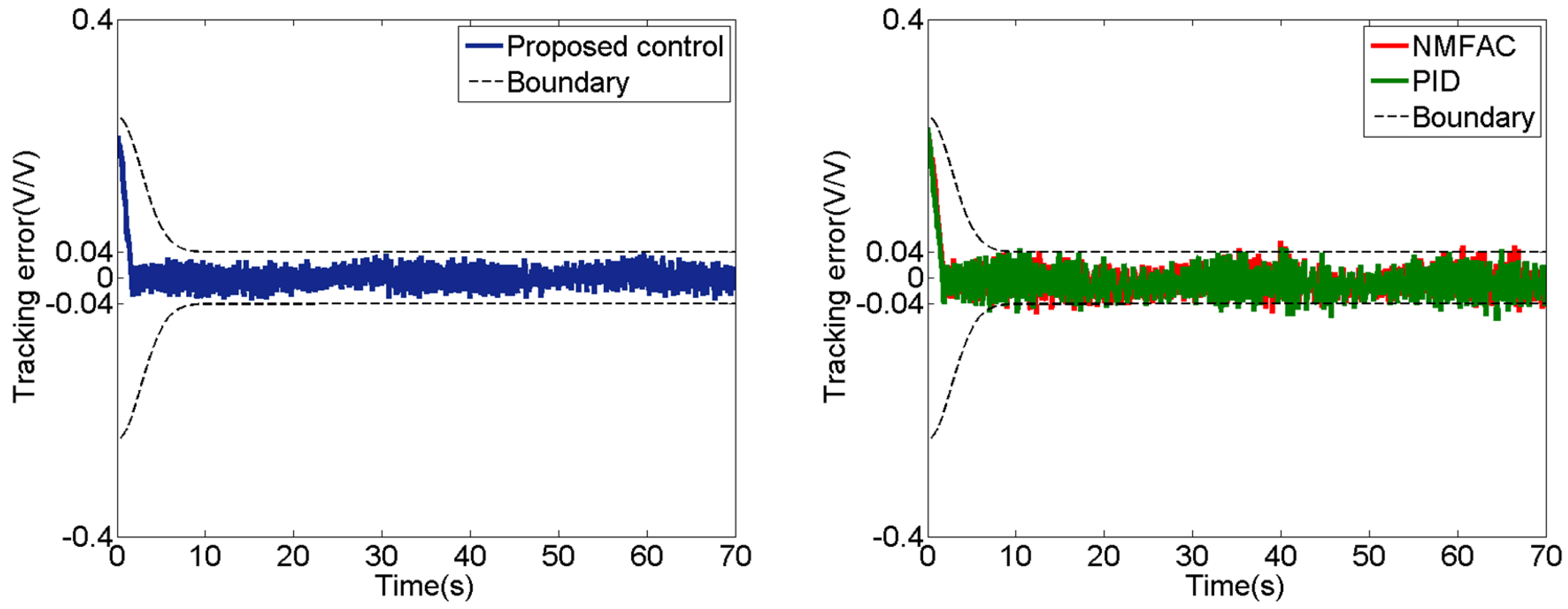
  • Experiments are implemented on an SMA-based robotic hand to testify that the proposed control method has a remarkable performance compared with PID and new model free adaptive control (NMFAC).
In the following parts of this paper, the structure is constructed as follows. In Section 2 and Section 3, the preliminaries are stated. A model free adaptive control method with DLT and PPC is introduced in Section 4. Then, the experiment’s results and analysis are given in Section 5. Section 6 summarizes the whole paper.

2. SMA-Based Robotic Hand

As shown in Figure 1, the proposed SMA-based robotic hand consists of five separate robotic fingers. Each finger is actuated by an SMA actuator to perform a single degree of freedom bending motion. The bending sensor is installed in the back of the finger, which is shown in Figure 2.
Figure 3 shows the internal structure of the robotic finger. Each finger is actuated by one SMA actuator. The SMA actuator is linked with the joint to achieve one freedom bending motion. Therefore, the finger has an underactuated motion mode. The novel part of the SMA-based robotic hand is the magnet reset device. The magnet reset device is connected with the joint to ensure the finger to restore original position.
As shown in Figure 4, the robotic hand system includes a PC, a controller (Arduino Mega 2560), a bending sensor (flex4.5”, Flex International Ltd., Milpitas, CA, USA), a driver module, an SMA actuator (MigaOne-15, Miga Motor Company, Silverton, CO, USA) and the robotic finger. The control programs are performed in the PC, which is used to obtain the output data. Then, the PC transmits the control input data to the controller. After gaining the commands from the PC, the controller is instructed to drive the SMA actuator to perform the bending motion of the robotic finger through the driver module. Once the finger is driven to bend, the bending sensor can bend with the finger. Then, it can measure the bending value and transmit the bending signal to PC.

3. Problem Formulation

3.1. System Model

A single input single output (SISO) discrete time nonlinear system can be presented as follows
y ( k + 1 ) = f ( y ( k ) , y ( k 1 ) , y ( k d y ) , u ( k ) , u ( k 1 ) , u ( k d u ) ) ,
where at time k, y ( k ) ,   u ( k ) R stand for the output and input, respectively, d y , d u R represent the unknown order, and f ( · ) is a nonlinear function.
Assumption 1.
The partial derivatives of f ( · ) with respect to the ( d y + 2 ) t h variable is continuous.
Assumption 2.
System (1) satisfies the generalized Lipschitz condition, that is, y ( k 1 + 1 ) y ( k 2 + 1 ) n u ( k 1 ) u ( k 2 ) for u ( k 1 ) u ( k 2 ) and any k 1 k 2 , k 1 ,   k 2 0 , and n is a positive constant.
In [32], a novel dynamic linearization model is presented as follows:
Theorem 1.
Considering system (1), which satisfies Assumptions 1 and 2, there must exist the time-varying parameters M ( k ) and B ( k ) , by which system (1) can be converted into another form as follows:
y ( k + 1 ) = M ( k ) + Δ u ( k ) B ( k ) ,
where Δ u = u ( k ) u ( k 1 ) .
The estimation of M ( k ) can be defined as
M ^ ( k ) = y ( k ) Δ u ( k 1 ) B ^ ( k 1 ) ,
where M ^ ( k ) and B ^ ( k ) are the estimations of M ( k ) and B ( k ) .
Two cost functions proposed in [32] for parameter estimation and control input are applied as follows:
J ( u ( k ) ) = y d y ^ ( k + 1 ) r d ^ ( k ) 2 + θ u ( k ) u ( k 1 ) 2
J ( B ^ ( k ) ) = B ^ ( k ) y ( k ) M ^ ( k 1 ) Δ u ( k 1 ) 2 + α B ^ ( k ) B ^ ( k 1 ) 2 ,
where y d is the reference output, d ^ ( k ) stands for the estimated error of the model, r, α and θ are the design parameter.
Using optimal condition J ( B ^ ( k ) ) B ^ ( k ) = 0 and J ( u ( k ) ) u ( k ) = 0 , the following relationships are presented in the following:
B ^ ( k ) = B ^ ( k 1 ) + y ( k ) M ^ ( k 1 ) Δ u ( k 1 ) B ^ ( k 1 ) y ( k ) M ^ ( k 1 ) α + y ( k ) M ^ ( k 1 ) 2
u ( k ) = u ( k 1 ) + B ^ ( k ) y d ( k + 1 ) M ^ ( k ) r ( y ( k ) y ^ ( k ) ) 1 + θ B ^ 2 ( k ) .
The above control method is a new model free adaptive control (NMFAC) by [32]. For a robotic hand system, Assumption 1 can be hardly satisfied. However, Assumption 2 applies an upper limit on the the rate of system output change driven by the rate of system control input. From a practical point of view, the robotic hand system can meet Assumption 2. Therefore, the SMA-based robotic hand system can be written as:
y a ( k + 1 ) = y ( k + 1 ) + D ( k ) = f ( y ( k ) , y ( k 1 ) , , y ( k d y ) , u ( k ) , u ( k 1 ) , , u ( k d u ) ) + D ( k ) ,
where y a ( k + 1 ) and u ( k ) are the output and input of the robotic finger system, f ( k ) stands for the bounded disturbances with D ( k ) < D , D > 0 , and f ( · ) represents the discrete-time SISO nonlinear system (1).

3.2. Prescribed Performance Control

In order to ensure the tracking error of the system constrained in a predefined zone, PPC was proposed by [33]. this paper proposes a prescribed performance for nonlinear systems as follows:
ν ( k ) < e ( k ) < ν ( k ) ,
where ν ( k ) is a prescribed performance function, which is described in the following:
ν ( k + 1 ) = ( ν ( k ) ν ( ) ) ( 1 atan ( ε k ) / ( π π 2 2 ) ) + ν ( ) lim k ν ( k ) = ν ( ) ,
where the initial value satisfies ν ( 0 ) > ν ( ) > 0 , and ε is a positive constant correlated to the convergence rate. To deal with constrained tracking error, a monotone increasing function Ω ( μ ( k ) ) is designed to transform the constrained error e ( k ) into unconstrained error μ ( k ) as follows
e ( k ) = ν ( k ) Ω ( μ ( k ) ) .
The characteristics of the monotone increasing function Ω ( μ ( k ) ) are summarized as follows:
  • Ω ( μ ( k ) ) ( 1 , 1 ) , for all μ ( k ) R .
  • lim μ ( k ) Ω ( μ ( k ) ) = 1 , lim μ ( k ) + Ω ( μ ( k ) ) = 1 .
Since Ω ( μ ( k ) ) is increasing function and υ ( 0 ) > υ ( ) > 0 , the inverse transformation is given as:
μ ( k ) = Ω 1 ( e ( k ) υ ( k ) ) .
If υ ( 0 ) is determined appropriately to meet e ( 0 ) < υ ( 0 ) and ensure μ ( k ) limited, then Ω ( μ ( k ) ) ( 1 , 1 ) holds, following (8) holds.
According to the above analysis, a strictly increasing function is proposed for the proposed control method:
Ω ( μ ( k ) ) = μ ( k ) κ 2 + μ 2 ( k ) ,
where κ > 0 is a design parameter. Hence, one has
μ ( k ) = κ e ( k ) ν 2 ( k ) e 2 ( k ) .

4. Control Method Design

4.1. Disturbance Estimation

The disturbance D ( k ) in (8) can be estimated as follows:
D ^ ( k ) = D ( k 1 ) = y a ( k ) y ( k ) = y a ( k ) M ^ ( k 1 ) Δ u ( k 1 ) B ^ ( k 1 ) .
Then, we define the error of disturbance estimation in the following
D ˜ ( k ) = D ( k ) D ^ ( k ) .
Substituting (8) and (14) into (15) yields:
D ˜ ( k ) = y a ( k + 1 ) M ^ ( k ) Δ u ( k ) B ^ ( k ) ( y a ( k ) M ^ ( k 1 ) Δ u ( k 1 ) B ^ ( k 1 ) ) = ( y a ( k + 1 ) y a ( k ) ) ( M ^ ( k ) M ^ ( k 1 ) ) ( Δ u ( k ) B ^ ( k ) Δ u ( k 1 ) B ^ ( k 1 ) ) .
According to Assumption 2, (3), (6) and (7), one can conclude that y a ( k + 1 ) y a ( k ) , Δ u , M ^ ( k ) and B ^ ( k ) are bounded, which can lead to D ˜ ( k ) bounded.

4.2. Controller Design

Consider a discrete terminal sliding surface:
s ( k + 1 ) = s ( k ) + ρ 1 μ ( k + 1 ) ρ 2 μ α ( k ) ,
where ρ 1 and ρ 2 are positive constants, α is the ratio of two odd integers, with 0 < α < 1 .
Then, substituting (14) into (18) yields:
s ( k + 1 ) s ( k ) = ρ 1 κ e ( k + 1 ) ν 2 ( k + 1 ) e 2 ( k + 1 ) ρ 2 μ α ( k ) .
The tracking error is proposed in the following:
e ( k + 1 ) = y d y a ( k + 1 ) = y d M ^ ( k ) 1 B ^ ( k ) Δ u ( k ) D ^ ( k ) ,
where y d is the reference output. On the basis of the equivalent reaching law:
Δ s ( k ) = s ( k + 1 ) s ( k ) = 0 .
The control input is proposed in the following:
u ( k ) = u ( k 1 ) + u e q + u s w ,
where u e q and u s w are the equivalent control input and the switching control input, respectively. Then, from (17)–(19), one has:
u e q = B ^ ( k ) ( y d M ^ ( k ) D ^ ( k ) Γ ( k ) ) ,
where Γ ( k ) = ρ 2 μ α ( k ) ν ( k + 1 ) ( ρ 1 2 κ 2 + ρ 2 2 μ 2 α ( k ) ) .
To deal with the robustness of u e q ( k ) , define the following the switching control law
u s w = ξ B ^ ( k ) sign ( s ( k ) ) .
Substituting (18), (21) and (22) into (17) yields to:
Δ s ( k + 1 ) = s ( k + 1 ) s ( k ) = ρ 1 κ ( Γ ( k ) ξ s i g n ( s ( k ) ) ) ρ 2 μ α ( k ) ν 2 ( k + 1 ) ( Γ ( k ) ξ s i g n ( s ( k ) ) ) 2 ν 2 ( k + 1 ) ( Γ ( k ) ξ s i g n ( s ( k ) ) ) 2 .
It is notable that Γ ( k ) is bounded, that is, Γ ( k ) < Γ 0 . Then, ξ can be assumed to meet the requirements as follows:
Γ 0 ρ 2 μ α ( k ) ν 2 ( k + 1 ) ( Γ ( k ) ξ ) 2 ρ 1 κ < ξ < ρ 2 μ α ( k ) ν 2 ( k + 1 ) ( Γ ( k ) ξ ) 2 + 2 ν ( k + 1 ) ρ 1 κ Γ 0 s ( k ) > 0 Γ 0 + ρ 2 μ α ( k ) ν 2 ( k + 1 ) ( Γ ( k ) + ξ ) 2 ρ 1 κ < ξ < ρ 2 μ α ( k ) ν 2 ( k + 1 ) ( Γ ( k ) + ξ ) 2 + 2 ν ( k + 1 ) ρ 1 κ Γ 0 s ( k ) < 0 .
Finally, the control input is proposed as follows
u ( k ) = B ^ ( k ) ( y d M ^ ( k ) D ^ ( k ) Γ ( k ) ) + ξ B ^ ( k ) sign ( s ( k ) ) .
The schematic diagram of the control system is shown in Figure 5. The proposed control method merely depends on the I/O data. According to the reference output y d and the output of the SMA-based robotic hand y a ( k ) , the transformed error ν ( k 1 ) can be obtained. According to the I/O data of the SMA-based robotic hand, the estimation of time-varying parameters M ^ ( k 1 ) and B ^ ( k 1 ) can be obtained. Then, through sliding mode control, we can get the control input u ( k ) .

4.3. Stability Analysis

Theorem 2.
Consider the nonlinear system (8) with the discrete sliding mode function (18) meeting the requirements (26). If the sliding mode variable s ( k ) will finally reach a zone by the control law (27), μ ( k ) is constrained and the controlled system satisfies the prescribed performance.
Proof of Theorem 2.
As regards the proposed control method, the stability of the controlled system can be proved by the specific analysis including the following several classified discussions.
If s ( k ) > 0 , one has:
Δ s ( k + 1 ) = ρ 1 κ ( Γ ( k ) ξ ) ρ 2 μ α ( k ) ν 2 ( k + 1 ) ( Γ ( k ) ξ ) 2 ν 2 ( k + 1 ) ( Γ ( k ) ξ ) 2 .
From (24), the following result is obtained:
2 ν ( k + 1 ) ν 2 ( k + 1 ) ( Γ ( k ) ξ ) 2 < ρ 1 κ ( Γ ( k ) + Γ 0 2 ν ( k + 1 ) ρ 1 ε ) ρ 2 μ α ( k ) ν 2 ( k + 1 ) ( Γ ( k ) ξ ) 2 ν 2 ( k + 1 ) ( Γ ( k ) ξ ) 2 < Δ s ( k + 1 ) = ρ 1 κ ( Γ ( k ) ξ ) ρ 2 μ α ( k ) ν 2 ( k + 1 ) ( Γ ( k ) ξ ) 2 ν 2 ( k + 1 ) ( Γ ( k ) ξ ) 2 < 0 .
If s ( k ) < 0 , we have:
Δ s ( k + 1 ) = ρ 1 κ ( Γ ( k ) + ξ ) ρ 2 μ α ( k ) ν 2 ( k + 1 ) Γ 2 ( k ) ν 2 ( k + 1 ) Γ 2 ( k ) .
According to (24), one can obtain:
0 < Δ s ( k + 1 ) = ρ 1 κ ( Γ ( k ) + ξ ) ρ 2 μ α ( k ) ν 2 ( k + 1 ) ( Γ ( k ) + ξ ) 2 ν 2 ( k + 1 ) ( Γ ( k ) + ξ ) 2 < ρ 1 κ ( Γ ( k ) + Γ 0 + 2 ν ( k + 1 ) ρ 1 ε ) ρ 2 μ α ( k ) ν 2 ( k + 1 ) ( Γ ( k ) + ξ ) 2 ν 2 ( k + 1 ) ( Γ ( k ) + ξ ) 2 < 2 ν ( k + 1 ) ν 2 ( k + 1 ) ( Γ ( k ) + ξ ) 2 .
Hence, Δ s ( k ) s ( k ) < 0 and 2 ν ( k + 1 ) ν 2 ( k + 1 ) ( Γ ( k ) ξ ) 2 < Δ s ( k ) < 2 ν ( k + 1 ) ν 2 ( k + 1 ) ( Γ ( k ) + ξ ) 2
Then, we define a boundary Θ with respect to s ( k ) , which is expressed as follows:
Φ = s ( k ) | 2 ν ( k + 1 ) ν 2 ( k + 1 ) ( Γ ( k ) ξ ) 2 < s ( k ) < 2 ν ( k + 1 ) ν 2 ( k + 1 ) ( Γ ( k ) + ξ ) 2 .
Case 1. If s ( k ) Φ , two situations should be considered in the following:
  • If s ( k ) > 2 ν ( k + 1 ) ν 2 ( k + 1 ) ( Γ ( k ) + ξ ) 2 , based on (27), s ( k ) will monotonically decrease until it falls into Θ .
  • If s ( k ) < 2 ν ( k + 1 ) ν 2 ( k + 1 ) ( Γ ( k ) + ξ ) 2 , based on (27), s ( k ) can increase until it arrives to Θ .
Hence, s ( k ) can reach Φ finally under this case.
Case 2. If s ( k ) Φ , the analysis should also be separated including two conditions as follows (1) If 0 < s ( k ) < 2 ν ( k + 1 ) ν 2 ( k + 1 ) ( Γ ( k ) + ξ ) 2 , combining (24) and (27) leads to
2 ν ( k + 1 ) ν 2 ( k + 1 ) ( Γ ( k ) ξ ) 2 < s ( k + 1 ) < 2 ν ( k + 1 ) ν 2 ( k + 1 ) ( Γ ( k ) + ξ ) 2 .
If 2 ν ( k + 1 ) ν 2 ( k + 1 ) ( Γ ( k ) ξ ) 2 < s ( k ) < 0 , in view of (24) and (39) one has
2 ν ( k + 1 ) ν 2 ( k + 1 ) ( Γ ( k ) ξ ) 2 < s ( k + 1 ) < 2 ν ( k + 1 ) ν 2 ( k + 1 ) ( Γ ( k ) + ξ ) 2 .
Therefore, the above analysis indicates s ( k + 1 ) Φ . Accordingly, it is proved that s ( k ) can be constrained in Φ . A definition is proposed as follows:
s ( k ) Φ s ,
where Φ s = max ( | 2 ν ( k + 1 ) ν 2 ( k + 1 ) ( Γ ( k ) ξ ) 2 | , | 2 ν ( k + 1 ) ν 2 ( k + 1 ) ( Γ ( k ) + ξ ) 2 | ) . Notice that Φ s will decrease as with the increase of k, since ν ( k ) is a decreasing function.
Based on (16), one obtains:
μ ( k + 1 ) = s ( k + 1 ) s ( k ) + ρ 2 μ α ( k ) ρ 1 .
By the triangle inequality, it is worth noting that:
μ ( k + 1 ) s ( k + 1 ) + s ( k ) + ρ 2 μ α ( k ) ρ 1 s ( k + 1 ) + s ( k ) + ρ 2 μ ( k ) ρ 1 .
According to Lemma 13.1 in [37], one can further obtain:
lim k μ ( k ) = 2 Φ s ρ 1 ρ 2 .
In conclusion, the transformed error μ ( k ) can be bounded which reveals that the tracking error e ( k ) is ensured in a predefined boundary (6). □

5. Experiment Studies

This section proposes three experiments implemented on the SMA-based robotic hand to confirm the performance of the presented control method. To better describe the motion of the proposed robotic hand, the output data of the bending sensor are normalized as the value from 0 to 1.

5.1. Experiment of Step Signal

A step command of 0.5(V/V) is applied to testify the tracking performance at steady and the response time. The main parameters of the proposed method is chosen as: ε = 0.00002 , υ ( ) = 0.01 , κ = 1 , ρ 1 = 0.5 , ρ 2 = 0.4 , α = 3 / 5 , ξ = 0.1 . As shown in Figure 6, the experimental results are presented for the comparisons of the response time and the steady state error. For simplicity, Table 1 shows the root mean square tracking error (RMSTE) at steady state and the response time. From the results, the response of the PID is faster than that of the proposed method. However, from the comparisons it can be concluded that the tracking accuracy of the presented control is higher. Moreover, from Figure 7 the tracking error is ensured in a preassigned zone by the proposed control.

5.2. Experiment of Sinusoidal Signal

In this section, a sinusoidal signal is adopted for the comparison of the control performance. Figure 8 and Figure 9 show the tracking performance and the tracking error, respectively. The RMSTE of PID, NMFAC and the proposed control method are 0.0198, 0.0197, and 0.0126. The control accuracy of the proposed control method is higher than those of the other methods. Furthermore, the proposed control can limit the tracking error in the predefined boundary in contrast with the other methods.

5.3. Experiment of Sinusoidal Signal with Time Variation

For further investigating the performance of the proposed control method, a sinusoidal signal with time variation is applied as the reference to compare the presented method with PID and the new MFAC. The sinusoidal signal is described as follows:
y d = 0.1 cos ( 2 π t / 50 ) + 0.075 sin ( 2 π t / 30 ) + 0.05 cos ( 2 π t / 25 ) + 0.2 .
From the results in Figure 10 and Figure 11, the three control methods can track the reference signal. However, PID and NMFAC cannot ensure the tracking error in a limited boundary. The proposed method can constrain the tracking error within a predefined domain.

6. Conclusions

Conventional robotic hands, which involve rigid components, such as linkages, gears and motors, have a large volume and heavy mass. Therefore, conventional robotic hands are unsafe and exhibit poor adaptability when they interact with humans or the surrounding environment. SMA as a novel smart material with the characteristics of a simple structure, small volume and light weight can be easily integrated into a robotic hand without requiring a large amount of space and complex gearing mechanisms. Moreover, the inherently high energy density makes SMA a natural choice for robotic hands. In this paper, the SMA-based robotic hand can be applied in a wide range of fields. For example, the robotic hand can serve people and help to grasp objects for a safe interaction. Moreover, in the field of agriculture, the robotic hand can pick the fruits compliantly. However, SMA has the characteristic of nonlinearity, due to the “shape memory effect” of SMA between a low-temperature martensite phase and a high temperature austenite phase, which leads to the complexity and difficulty of controlling the SMA-based robotic hand. Therefore, this paper focuses on the control method of the SMA-based robotic hand. A model-free adaptive control method with a prescribed performance is proposed for the SMA-based robotic hand. Combined with the Taylor series and Differential mean value theorem, a novel dynamic linearization technique is used to describe the system of the robotic hand. By applying PPC, the constrained tracking error can be converted into an unconstrained form to ensure the tracking error within a prescribed zone. Finally, experiments on the SMA-based robotic hand are conducted to verify the performance of the proposed control method. The results indicate that the proposed control method can ensure that the robotic hand tracks the reference signals and limits the tracking error in a predefined boundary.

Author Contributions

Literature search, software, data curation and writing—original draft, L.H.; writing—review and editing, J.X. and W.L. All authors have read and agreed to the published version of the manuscript.

Funding

This work was supported by National Natural Science Foundation of China under grant number 62073063.

Institutional Review Board Statement

Not applicable.

Informed Consent Statement

Not applicable.

Data Availability Statement

Data is contained within the article.

Conflicts of Interest

The authors declare no conflict of interest.

References

  1. Abondance, S.; Teeple, C.B.; Wood, R.J. A Dexterous Soft Robotic Hand for Delicate In-Hand Manipulation. IEEE Robot. Autom. Lett. 2020, 5, 5502–5509. [Google Scholar] [CrossRef]
  2. Liu, H.; Selvaggio, M.; Ferrentino, P.; Moccia, R.; Pirozzi, S.; Bracale, U.; Ficuciello, F. The MUSHA Hand II:A Multifunctional Hand for Robot-Assisted Laparoscopic Surgery. IEEE/ASME Trans. Mechatron. 2021, 26, 393–404. [Google Scholar]
  3. Sui, D.; Zhu, Y.; Zhao, S.; Wang, T.; Agrawal, S.; Zhang, H.; Zhao, J. A Bioinspired Soft Swallowing Gripper for Universal Adaptable Grasping. Soft Robot. 2020. [Google Scholar] [CrossRef]
  4. Lu, Y.; Xie, Z.; Wang, J.; Yue, H.; Wu, M.; Liu, Y. A novel design of a parallel gripper actuated by a large-stroke shape memory alloy actuator. Int. J. Mech. Sci. 2019, 159, 74–80. [Google Scholar] [CrossRef]
  5. Wang, W.; Tang, Y.; Li, C. Controlling bending deformation of a shape memory alloy-based soft planar gripper to grip deformable objects. Int. J. Mech. Sci. 2021, 193, 106181. [Google Scholar] [CrossRef]
  6. Zhong, G.; Hou, Y.; Dou, W. A soft pneumatic dexterous gripper with convertible grasping modes. Int. J. Mech. Sci. 2019, 153, 445–456. [Google Scholar] [CrossRef]
  7. Zhang, Z.; Ni, X.; Wu, H.; Sun, M.; Bao, G.; Wu, H.; Jiang, S. Pneumatically Actuated Soft Gripper with Bistable Structures. Soft Robot. 2021. [Google Scholar] [CrossRef]
  8. Shintake, J.; Rosset, S.; Schubert, B.; Floreano, D.; Shea, H. Versatile soft grippers with intrinsic electroadhesion based on multifunctional polymer actuators. Adv. Mater. 2016, 28, 231–238. [Google Scholar] [CrossRef] [PubMed]
  9. Shian, S.; Bertoldi, K.; Clarke, D.R. Dielectric elastomer based “grippers” for soft robotics. Adv. Mater. 2015, 27, 6814–6819. [Google Scholar] [CrossRef]
  10. Rodrigue, H.; Wang, W.; Han, M.W.; Kim, T.J.; Ahn, S.H. An overview of shape memory alloy-coupled actuators and robots. Soft Robot. 2017, 4, 3–15. [Google Scholar] [CrossRef] [PubMed]
  11. Lee, J.H.; Okamoto, S.; Matsubara, S. Development of multi-fingered prosthetic hand using shape memory alloy type artificial muscle. Comput. Technol. Appl. 2012, 3, 477–484. [Google Scholar]
  12. Bundhoo, V.; Haslam, E.; Birch, B.; Park, E.J. A shape memory alloy-based tendon-driven actuation system for biomimetic artificial fingers, part I: Design and evaluation. Robotica 2009, 27, 131–146. [Google Scholar] [CrossRef] [Green Version]
  13. Maeno, T.; Hino, T. Miniature five-fingered robot hand driven by shape memory alloy actuators. In Proceedings of the 12th IASTED International Conference, Robotics and Applications, Honolulu, HI, USA, 23–25 August 2006; pp. 174–179. [Google Scholar]
  14. Simone, F.; Rizzello, G.; Seelecke, S. Metal muscles and nerves—A self-sensing SMA-actuated hand concept. Smart Mater. Struct. 2017, 26, 095007. [Google Scholar] [CrossRef]
  15. Wang, W.; Ahn, S.H. Shape memory alloy-based soft gripper with variable stiffness for compliant and effective grasping. Soft Robot. 2017, 4, 379–389. [Google Scholar] [CrossRef] [PubMed]
  16. Liu, M.; Hao, L.; Zhang, W.; Zhao, Z. A novel design of shape-memory alloy-based soft robotic gripper with variable stiffness. Int. J. Adv. Robot. Syst. 2020, 17, 1729881420907813. [Google Scholar] [CrossRef]
  17. Jayender, J.; Patel, R.V.; Nikumb, S.; Ostojic, M. Modeling and Control of Shape Memory Alloy Actuators. IEEE Trans. Control Syst. Technol. 2008, 16, 279–287. [Google Scholar] [CrossRef]
  18. Dutta, S.; Ghorbel, F. Differential hysteresis modeling of a shape memory alloy wire actuator. IEEE/ASME Trans. Mechatron. 2005, 10, 189–197. [Google Scholar] [CrossRef]
  19. Wiest, J.H.; Buckner, G.D. Indirect Intelligent Sliding Mode Control of Antagonistic Shape Memory Alloy Actuators Using Hysteretic Recurrent Neural Networks. IEEE Trans. Control Syst. Technol. 2014, 22, 921–929. [Google Scholar] [CrossRef]
  20. Hannen, J.C.; Crews, J.H.; Buckner, G.D. Indirect intelligent sliding mode control of a shape memory alloy actuated flexible beam using hysteretic recurrent neural networks. Smart Mater. Struct. 2012, 21, 085015. [Google Scholar] [CrossRef] [Green Version]
  21. Lee, J.; Jin, M.; Ahn, K.K. Precise tracking control of shape memory alloy actuator systems using hyperbolic tangential sliding mode control with time delay estimation. Mechatronics 2013, 23, 310–317. [Google Scholar] [CrossRef]
  22. Kha, N.B.; Ahn, K.K. Position control of shape memory alloy actuators by using self tuning fuzzy PID controller. In Proceedings of the 2006 1ST IEEE Conference on Industrial Electronics and Applications, Singapore, 24–26 May 2006; pp. 1–5. [Google Scholar]
  23. Nakshatharan, S.S.; Dhanalakshmi, K.; Ruth, D.J.S. Fuzzy based sliding surface for shape memory alloy wire actuated classical super-articulated control system. Appl. Soft Comput. 2015, 32, 580–589. [Google Scholar] [CrossRef]
  24. Yan, S.; Yang, T.; Liu, X.; Wang, R. Tactile feedback control for a gripper driven by SMA springs. AIP Adv. 2012, 2, 032134. [Google Scholar] [CrossRef] [Green Version]
  25. Nikdel, N.; Nikdel, P.; Badamchizadeh, M.A.; Hassanzadeh, I. Using neural network model predictive control for controlling shape memory alloy-based manipulator. IEEE Trans. Ind. Electron. 2013, 61, 1394–1401. [Google Scholar] [CrossRef]
  26. Chaitanya, S.K.; Dhanalakshmi, K. Control of shape memory alloy actuated gripper using Sliding Mode Control. In Proceedings of the 2013 IEEE International Conference on Control Applications (CCA), Hyderabad, India, 28–30 August 2013; pp. 1247–1252. [Google Scholar]
  27. Silva, A.F.; da Silva, S.A.; dos Santos, A.J.; Ries, A.; Souto, C.R.; de Araújo, C.J. Fuzzy control of a robotic finger actuated by shape memory alloy wires. J. Dyn. Syst. Meas. Control 2018, 140, 064502. [Google Scholar] [CrossRef]
  28. Khodayari, A.; Talari, M.; Kheirikhah, M.M. Fuzzy PID controller design for artificial finger based SMA actuators. In Proceedings of the 2011 IEEE International Conference on Fuzzy Systems (FUZZ-IEEE 2011), Taipei, Taiwan, 27–30 June 2011; pp. 727–732. [Google Scholar]
  29. Jung, S.; Bae, J.; Moon, I. Lightweight prosthetic hand with five fingers using SMA actuator. In Proceedings of the 2011 11th International Conference on Control, Automation and Systems, Gyeonggi-do, Korea, 26–29 October 2011; pp. 1797–1800. [Google Scholar]
  30. Simone, F.; York, A.; Seelecke, S. Design and fabrication of a three-finger prosthetic hand using SMA muscle wires. In Bioinspiration, Biomimetics, and Bioreplication 2015; International Society for Optics and Photonics: Bellingham, WA, USA, 2015; Volume 9429, p. 94290T. [Google Scholar]
  31. Andrianesis, K.; Tzes, A. Development and control of a multifunctional prosthetic hand with shape memory alloy actuators. J. Intell. Robot. Syst. 2015, 78, 257–289. [Google Scholar] [CrossRef]
  32. Deng, K.; Li, F.; Yang, C. A New Data-Driven Model-Free Adaptive Control for Discrete-Time Nonlinear Systems. IEEE Access 2019, 7, 126224–126233. [Google Scholar] [CrossRef]
  33. Bechlioulis, C.P.; Rovithakis, G.A. Robust adaptive control of feedback linearizable MIMO nonlinear systems with prescribed performance. IEEE Trans. Autom. Control 2008, 53, 2090–2099. [Google Scholar] [CrossRef]
  34. Liu, D.; Yang, G.H. Prescribed Performance Model-Free Adaptive Integral Sliding Mode Control for Discrete-Time Nonlinear Systems. IEEE Trans. Neural Netw. Learn. Syst. 2019, 30, 2222–2230. [Google Scholar] [CrossRef]
  35. Nguyen, M.L.; Chen, X.; Yang, F. Discrete-Time Quasi-Sliding-Mode Control With Prescribed Performance Function and its Application to Piezo-Actuated Positioning Systems. IEEE Trans. Ind. Electron. 2018, 65, 942–950. [Google Scholar] [CrossRef]
  36. Zhang, W.; Xu, D.; Jiang, B.; Pan, T. Prescribed performance based model-free adaptive sliding mode constrained control for a class of nonlinear systems. Inf. Sci. 2021, 544, 97–116. [Google Scholar] [CrossRef]
  37. Spooner, J.T.; Maggiore, M.; Ordonez, R.; Passino, K.M. Stable Adaptive Control and Estimation for Nonlinear Systems: Neural and Fuzzy Approximator Techniques; John Wiley & Sons: Hoboken, NJ, USA, 2004; Volume 43. [Google Scholar]
Figure 1. SMA-based robotic hand.
Applsci 11 09040 g001
Figure 2. Position of bending sensor.
Applsci 11 09040 g002
Figure 3. SMA-based robotic hand.
Applsci 11 09040 g003
Figure 4. Hardware system of the SMA-based robotic hand.
Applsci 11 09040 g004
Figure 5. Schematic diagram of control system.
Applsci 11 09040 g005
Figure 6. Tracking results under the step signal.
Applsci 11 09040 g006
Figure 7. Tracking error under the step signal.
Applsci 11 09040 g007
Figure 8. Tracking results under the sinusoidal signal.
Applsci 11 09040 g008
Figure 9. Tracking error under the sinusoidal signal.
Applsci 11 09040 g009
Figure 10. Tracking results under the time-varying signal.
Applsci 11 09040 g010
Figure 11. Tracking error under the time-varying signal.
Applsci 11 09040 g011
Table 1. Comparisons of control performance.
Control MethodRMSTE (V/V)Response Time (s)
PID0.00464.9
NMFAC0.00615.2
Proposed control0.00255.0
Publisher’s Note: MDPI stays neutral with regard to jurisdictional claims in published maps and institutional affiliations.

