Article

Analysis and Experimental Verification of Mechanical Errors in Nine-Link Type Double-Toggle Mold/Die Clamping Mechanisms

1
Department of Mechanical and Mechatronic Engineering, National Taiwan Ocean University, Keelung 20224, Taiwan
2
Department of Mechanical Engineering, National Taiwan University, Taipei 10617, Taiwan
*
Author to whom correspondence should be addressed.
Appl. Sci. 2021, 11(2), 832; https://doi.org/10.3390/app11020832
Submission received: 30 November 2020 / Revised: 5 January 2021 / Accepted: 11 January 2021 / Published: 17 January 2021
(This article belongs to the Special Issue Mechanical Tolerance Analysis in the Era of Industry 4.0)

Abstract

:

Featured Application

This work can be applied to the tolerance analysis and mechanical error detection of double-toggle mold/die clamping mechanisms, and could be applicable to improve conventional injection molding machines and die casting machines to meet partial requirements of the machine layer in a smart factory framework.

Abstract

Nine-link type double-toggle mold/die clamping mechanisms are widely used in modern injection molding machines and die casting machines in order to provide sufficient mold/die clamping force for counteracting the pressure occurred inside molds/dies. In this paper, the analysis and experimental evaluation of mechanical errors in nine-link type double-toggle mold/die clamping mechanisms are presented. The kinematic error equations of the output link (i.e., the moving platen) caused by dimensional errors (or tolerances) of link members are derived analytically through the concept of tolerance sensitivity analysis. Evaluation indices based on the asymmetry of the mold/die clamping mechanism caused by mechanical errors are established. A case study is then given to demonstrate the derived analytical equations and the established evaluation indices. Subsequently, a prototype for performing the experimental evaluation is conceptually designed and was actually constructed. Experiments were conducted for evaluating the quantitative influence of mechanical errors on the operating performance of the constructed mold/die clamping mechanism. According to the experimental results, response surface modelling for benefiting the constructed mold/die clamping mechanism with better operating performance could be performed. The presented research results will be helpful in the tolerance analysis and mechanical error detection of nine-link type double-toggle mold/die clamping mechanisms.

1. Introduction

Nine-link type double-toggle mold/die clamping mechanisms are widely used in modern injection molding machines and die casting machines in order to provide sufficient mold/die clamping force for counteracting the pressure occurred inside molds/dies [1,2]. The perspective view of a nine-link type mold/die clamping mechanism is illustrated in Figure 1, and its perspective sectional view is also depicted in Figure 2. Such a mechanism, also known as a five-point double-toggle mold/die clamping mechanism, is part of an injection molding machine or of a die casting machine. The mechanism shown in the figures basically consists of a fundamental structure A1, a moving platen A2, and a linkage assembly A3. The fundamental structure A1, as an immovable frame of the mechanism, is mainly comprised of a base A1-1, a stationary platen A1-2, a tail stock platen A1-3, four tie bars A1-4, and a hydraulic cylinder A1-5. The moving platen A2, which is constrained by the four parallel tie bars A1-4, can only translate along the axial direction of the tie bars. In order to drive the moving platen, the linkage assembly A3 is set up between the tail stock platen A1-3 and the moving platen A2 and is actuated by a piston of the hydraulic cylinder A1-5. Two half-molds/dies (not shown in the figures) are firmly installed on the stationary platen A1-2 and the moving platen A2, respectively, and can be closed or opened during the injection molding or die casting process when the moving platen A2 is driven by the linkage assembly A3 to translate forward or backward.
Three configurations of the nine-link type mold/die clamping mechanism, for illustrating its initial position, intermediate position, and toggle position, respectively, are shown in Figure 3. When the mechanism is in its initial position, as shown in Figure 3a, both the piston of the hydraulic cylinder (i.e., the input link member) and the moving platen (i.e., the output link member) are at their initial positions, and the two half-molds/dies (not shown) are entirely opened. When the mechanism is in its intermediate position, as shown in Figure 3b, both the input and output link members translate forward (rightward) from their initial positions, and the two half-molds/dies (not shown) are closing. When the mechanism is in its toggle position, as shown in Figure 3c, both the input and output link members are at their limit positions, and the two half-molds/dies (not shown) are entirely closed. It must be noted in Figure 3c that, the three revolute joints A, B, and C are collinear at that instant, so are the three revolute joints D, E, and F; such geometric relations form the well-known double-toggle configuration. Such a double-toggle configuration can theoretically achieve an infinite mechanical advantage (MA) [3] for providing sufficient mold/die clamping force to counteract large pressure occurred inside molds/dies.
Referring to Figure 1, Figure 2 and Figure 3, the nine-link type double-toggle mold/die clamping mechanism topologically consists of nine links, ten revolute joints, and two prismatic joints. According to Grubler–Kutzbach criteria [3], the number of degree-of-freedom (DOF, i.e., the mobility) of such a planar mechanism should be
F p = 3 ( N 1 ) 2 ( J R + J P ) = 3 ( 9 1 ) 2 ( 10 + 2 ) = 0
in which, N, JR, and JP are the numbers of links, revolute joints, and prismatic joints, respectively. When the number of DOF of a mechanism is less than one, it is theoretically a structure or an overconstrained mechanism, i.e., the mechanism should be immovable. However, this mold/die clamping mechanism is actually movable and does not agree with the Grubler–Kutzbach criteria. That is, such a planar mechanism is a paradoxical overconstrained mechanism [3] with zero DOF. This nine-link type mechanism can be regarded as a combination of two symmetric Watt-II six-link type mechanisms along the central axis of the piston of the hydraulic cylinder (i.e., the input link). Therefore, the nine-link type double-toggle mold/die clamping mechanism is actually with one DOF because of the special geometric relation of a symmetric configuration.
There have been many studies on the presented nine-link type mold/die clamping mechanism because it has been widely adopted by industry for years. Fung et al. [4] investigated the inverse dynamics problem of the presented mechanism so as to determine the required driving forces. Lin and his colleagues estimated the friction effects at pin joints of the presented mechanism [5] and provided dimensional improvements to enhance its performance [6,7]. Huang et al. [8] adopted the genetic algorithm (GA) to optimize the key design parameters of the presented mechanism. Chiang et al. [9] developed a strategy, based on the use of decoupling fuzzy sliding-mode control, for implementing the integrated control of clamping force and energy-saving in a hydraulic injection molding machine. In recent years, Rao et al. [10] and Huang et al. [11,12] have respectively used strain gauge-based sensors to measure the elongations of the tie bars and to further estimate the clamping force with their developed methods. Zhao et al. [13] have also applied ultrasonic probes, which are installed on the ends of the tie bars, to measure the clamping force based on a proposed analytical model relating the ultrasonic propagation time to the clamping force of the presented mechanism. While substantial studies have been performed on the factors affecting the performance of the nine-link type mold/die clamping mechanisms, little effort has been made on the factor of manufacturing errors (i.e., mechanical errors caused by tolerances) of the dimensions and shapes of link members in such mechanisms. When manufacturing errors of the dimensions and shapes of link members in a nine-link type mold/die clamping mechanism are too large so that the geometric relation of a symmetric configuration cannot be maintained, the mechanism may transform into a structure that cannot easily produce a prescribed constrained motion. In other words, large driving force must be applied in order to produce a constrained motion, which causes compensative deformations of link members for counteracting the asymmetry due to dimensional errors, and thus leads to excessive wear, large deformations, and even fatigues of link members. As a result, the positioning accuracy and mold/die clamping performance of the mechanism will be considerably influenced by the manufacturing errors of link members.
In practice, there is a necessity to investigate the positioning degradation of a mechanism in terms of small deviations (or tolerances) of its geometric parameters. Such a necessary task in the machine design stage is called mechanical error analysis or tolerance sensitivity analysis. After the methodology for analyzing the four-bar linkage was proposed by Hartenberg and Denavit [14], many related works had appeared. Both Garrett and Hall [15] and Dhande and Chakraborty [16] attempted to evaluate the influence of link tolerances and joint clearances based on statistical approaches. Lakshminarayana and Narayanamurthi [17] suggested determining the mechanical errors due to link tolerances by deriving individual loop-closure equations. Choubey and Rao [18] predicted kinematic errors more accurately by taking both structural and mechanical errors into account. In addition to evaluate the kinematic error of the output link of the four-bar linkage due to imperfect dimensions and shapes of link members, there also exists numerous studies [19,20,21,22,23] on the mechanical error analysis in coupler curves of the four-bar linkage, the quick-return shaper mechanism [24], and Watt and Stephenson mechanisms [25]. With the extensive literature dealing with mechanisms whose mobilities follow the prediction of the Grubler–Kutzbach criteria, very few research had focused on the paradoxical overconstrained mechanisms which are more sensitive to dimensional deviations of link members. Therefore, the analysis and evaluation of mechanical errors in the presented nine-link type double-toggle mold/die clamping mechanism, a paradoxical overconstrained mechanism that violates the Grubler–Kutzbach criteria, has not been studied as yet.
Furthermore, more and more types of sensing devices, such as load cells and pressure transducers [9], strain gauge-based sensors [10,11,12], and ultrasonic probes [13], have already been used in related experimental studies for on-line measuring and/or detecting (monitoring) the operating conditions of a mold/die clamping mechanism. From a practical viewpoint, when the mechanical errors exist in the mold/die clamping units of real injection molding machines and die casting machines, experimental evaluations on their operating performance must also be carried out. To this end, the quantitative influence of mechanical errors on the operating performance of a mold/die clamping mechanism, based on the mechanical error detection, must be investigated via the use of some sensing devices. Informative data collected from such an experimental evaluation will be helpful for improving the injection molding and die casting machines and processes.
Therefore, this paper presents the theoretical analysis and experimental evaluation of mechanical errors in nine-link type double-toggle mold/die clamping mechanisms. The mechanical error analysis is carried out analytically and then demonstrated by a case study. A prototype for performing the experimental evaluation is conceptually designed and was actually constructed. Experiments were conducted for evaluating the quantitative influence of mechanical errors on the operating performance of the constructed mold/die clamping mechanism.

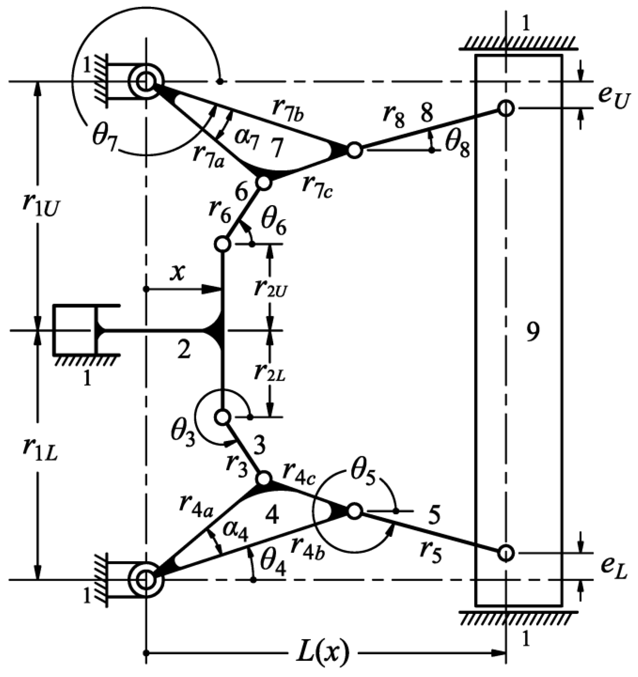
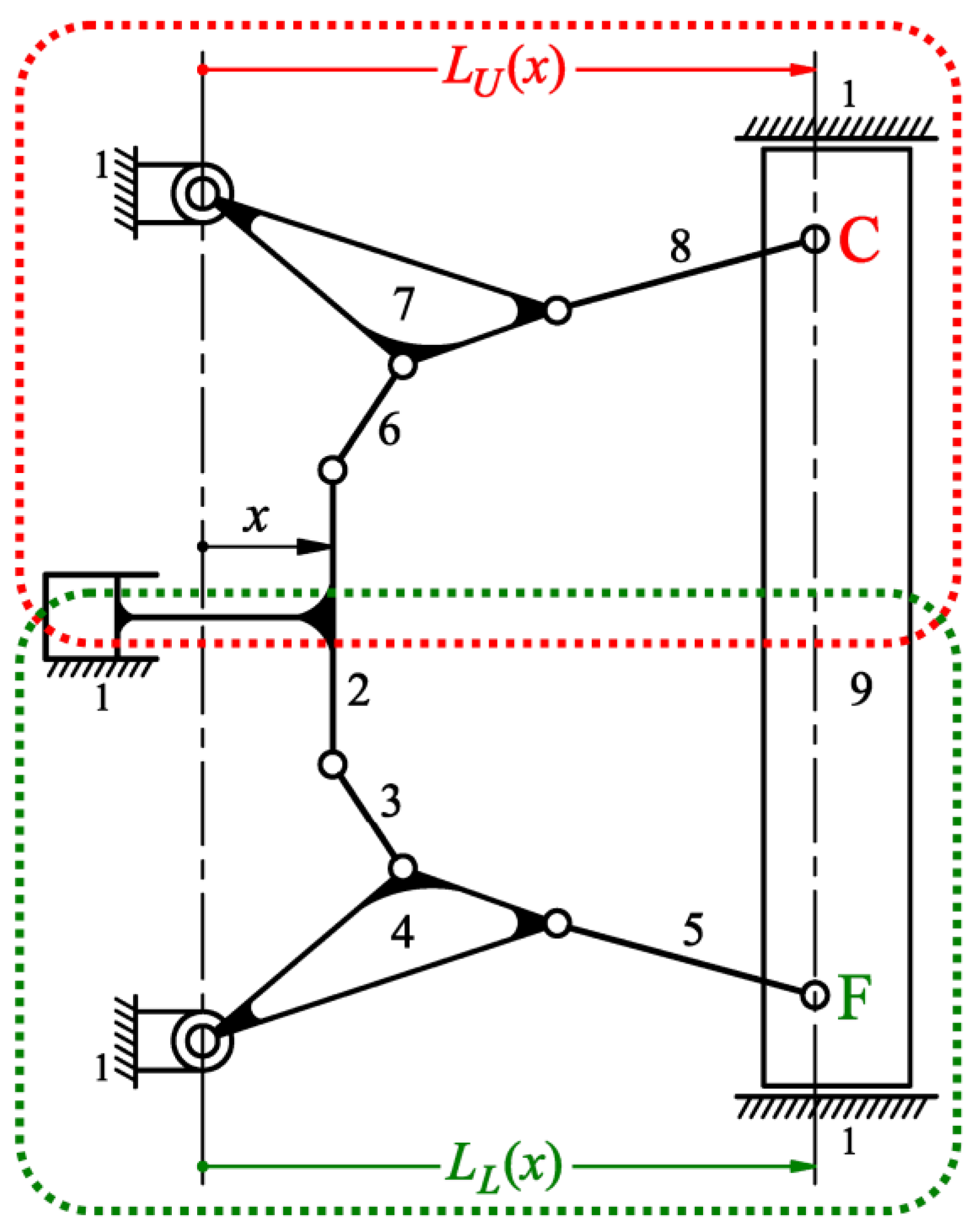
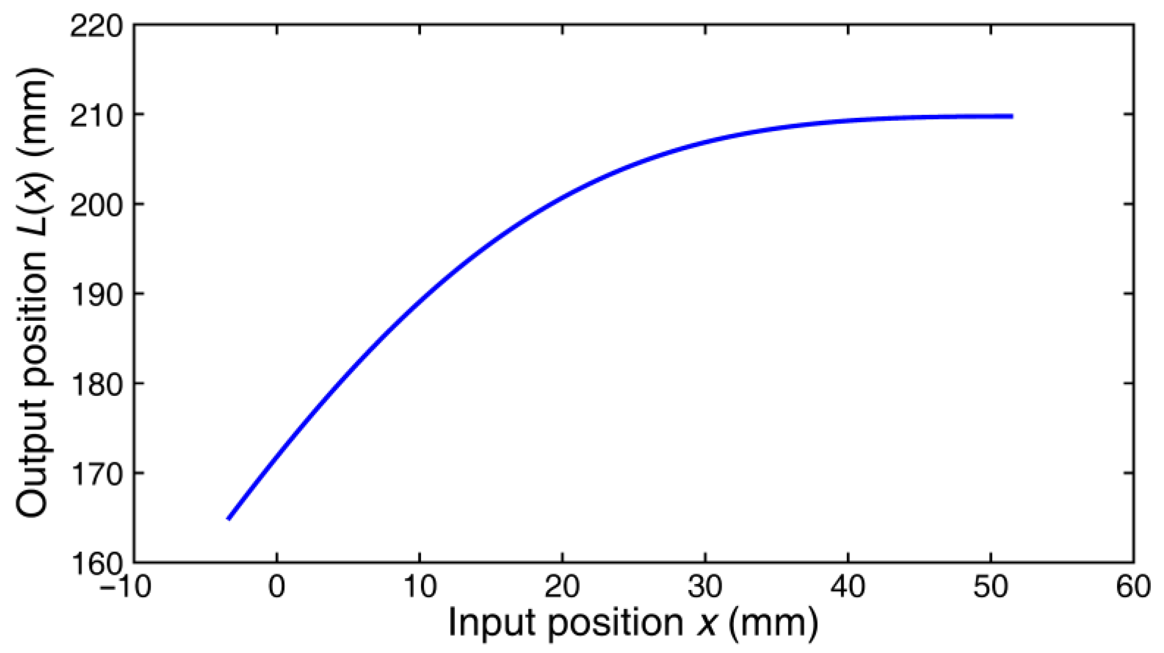
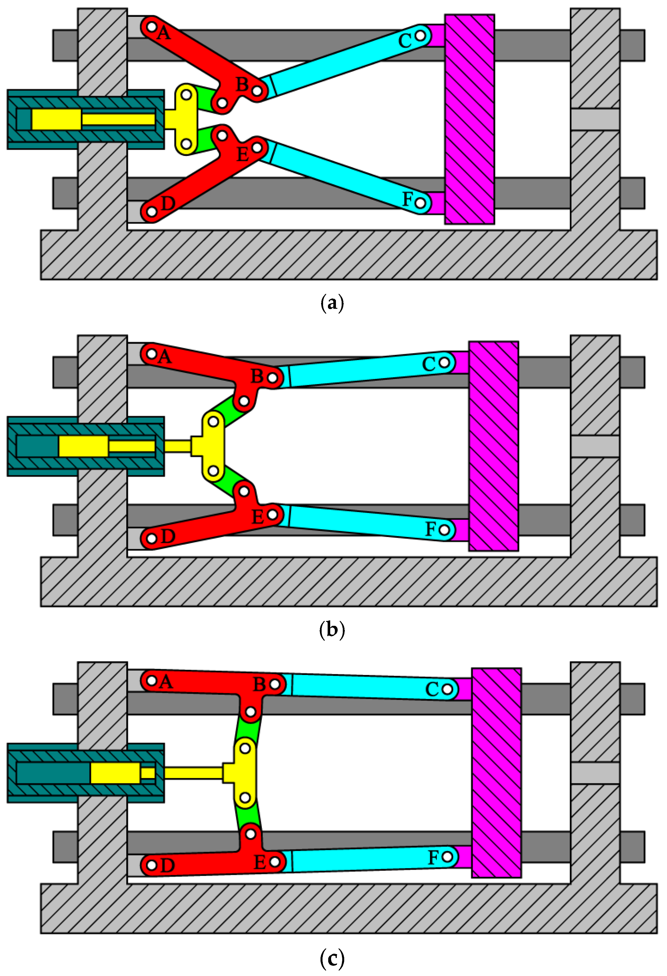
2. Position Analysis

In order to analyze the mechanical errors in a nine-link type double-toggle mold/die clamping mechanism, the position analysis must be performed first. Figure 4 shows the structural diagram of a nine-link type double-toggle mold/die clamping mechanism, in which, r1L, r1U, r2L, r2U, r3, r4a, r4b, r4c, α4, r5, r6, r7a, r7b, r7c, α7, and r8 are the geometric parameters (i.e., the dimensions) of respective links, eL and eU are the vertical offsets of the revolute joints between the output link (link 9) and the frame (link 1), x is the positional parameter of the input link (link 2) (i.e., the input variable that increases positively when link 2 moves rightward), L(x) is the linear position of the output link (link 9), and θ3, θ4, θ5, θ6, θ7, and θ8 are the angular positions of respective links increasing positively when the links rotate counterclockwise from the horizontal. Since the nine-link type mold/die clamping mechanism must satisfy the geometric relation of a symmetric configuration, thus the correlations of r1L = r1U, r2L = r2U, r3 = r6, r4a = r7a, r4b = r7b, r4c = r7c, α4 = α7, r5 = r8, and eL = eU exist. The linear position of the output link (link 9), L(x), can be expressed as
L ( x ) = r 4 b cos θ 4 + r 5 2 ( r 4 b sin θ 4 e L ) 2
or
L ( x ) = r 7 b cos θ 7 + r 8 2 ( r 7 b sin θ 7 + e U ) 2
in which, Equations (2) and (3) are derived from the lower and upper slider-crank chains of the mechanism shown in Figure 4, respectively, and θ4 and θ7 can be expressed as
θ 4 = 90 ° ( α 4 + γ 1 L + γ 2 L )
and
θ 7 = 270 ° + ( α 7 + γ 1 U + γ 2 U )
in which,
α 4 = cos 1 ( r 4 a 2 + r 4 b 2 r 4 c 2 2 r 4 a r 4 b )
γ 1 L = sin 1 ( x l L )
γ 2 L = cos 1 ( l L 2 + r 4 a 2 r 3 2 2 l L r 4 a )
α 7 = cos 1 ( r 7 a 2 + r 7 b 2 r 7 c 2 2 r 7 a r 7 b )
γ 1 U = sin 1 ( x l U )
γ 2 U = cos 1 ( l U 2 + r 7 a 2 r 6 2 2 l U r 7 a )
and
l L = x 2 + ( r 1 L r 2 L ) 2
l U = x 2 + ( r 1 U r 2 U ) 2
Thus, as θ4 and θ7 are solved by using Equations (4) and (5), respectively, the position of the output link, L(x), can be further solved by substituting them into Equations (2) and (3), respectively. Since the nine-link type mechanism essentially has a symmetric configuration, the use of Equations (2) or (3) will yield the same calculating result. For the remaining angular positions, they can be expressed as
θ 3 = 270 ° γ 1 L + cos 1 ( l L 2 + r 3 2 r 4 a 2 2 l L r 3 )
θ 5 = 360 ° sin 1 ( r 4 b sin θ 4 e L r 5 )
θ 6 = 90 ° + γ 1 U cos 1 ( l U 2 + r 6 2 r 7 a 2 2 l U r 6 )
θ 8 = sin 1 ( r 7 b sin θ 7 + e U r 8 )
As shown in Equations (2)–(17), the position analysis for the nine-link type double-toggle mold/die clamping mechanism can be solved analytically. The velocity and acceleration analyses may also be performed by differentiating Equations (2) and (3) with respect to time once and twice, respectively.

3. Mechanical Error Analysis

The mechanical errors, specifically the kinematic error equations, of the output link (i.e., link 9 shown in Figure 4) caused by dimensional errors (or tolerances) of link members can be derived analytically through the concept of tolerance sensitivity analysis [26,27,28]. To this end, the nine-link type double-toggle mold/die clamping mechanism is structurally divided into two sub-mechanisms as shown in Figure 5. As can be seen, the lower and upper sub-mechanisms are both Watt II six-link sub-mechanisms, and whose linear positions of the output link, LL(x) and LU(x), are defined by the horizontal positions of joints F and C relative to the fixed pivots, respectively. It must be emphasized that an error means the difference between the actual (measured) and nominal (theoretical) dimensions of a link member that has been machined, while a tolerance means the allowable deviation range (defined by allocated upper and lower deviations) of the nominal dimension of a link member. When performing the mechanical error analysis, the upper or lower deviations of the allocated dimensional tolerances are considered as the dimensional errors for simulating a worst situation of machined link members. The actually measured dimensional errors can also be used in the mechanical error analysis for evaluating a real condition.

3.1. Analysis of the Lower Sub-Mechanism

For the lower sub-mechanism shown in Figure 5, the constraint equation, relating the geometric parameters r1L, r2L, r3, r4a, r4b, r4c, r5, and eL to the input and output variables x and LL, may be written as
F L = r 4 b cos θ 4 ( x , r 1 L , r 2 L , r 3 , r 4 a , r 4 b , r 4 c )   + r 5 2 [ r 4 b sin θ 4 ( x , r 1 L , r 2 L , r 3 , r 4 a , r 4 b , r 4 c ) e L ] 2 L L = 0
in which, θ4 = θ4(x, r1L, r2L, r3, r4a, r4b, r4c) is defined by Equation (4). For small errors existing in all design parameters, the differentials of the function FL may be written in terms of their respective partial derivatives as
d F L Δ F L = F L r 1 L Δ r 1 L + F L r 2 L Δ r 2 L + F L r 3 Δ r 3 + F L r 4 a Δ r 4 a + F L r 4 b Δ r 4 b   + F L r 4 c Δ r 4 c + F L r 5 Δ r 5 + F L e L Δ e L + F L x Δ x + F L L L Δ L L = 0
If only Δr1L is considered to induce the output error ΔLL, the output error termed ΔL1L can be derived and expressed as
Δ L 1 L = F L / r 1 L F L / L L Δ r 1 L   = [ r 4 b ( cos θ 4 tan θ 5 sin θ 4 ) ( sin γ 1 L cos γ 1 L cot γ 2 L l L + cos γ 1 L r 4 a sin γ 2 L ) ] Δ r 1 L
If only Δr2L is considered to induce the output error ΔLL, the output error termed ΔL2L can be derived and expressed as
Δ L 2 L = F L / r 2 L F L / L L Δ r 2 L   = [ r 4 b ( cos θ 4 tan θ 5 sin θ 4 ) ( cos γ 1 L cot γ 2 L sin γ 1 L l L cos γ 1 L r 4 a sin γ 2 L ) ] Δ r 2 L
If only Δr3 is considered to induce the output error ΔLL, the output error termed ΔL3 can be derived and expressed as
Δ L 3 = F L / r 3 F L / L L Δ r 3 = [ r 3 r 4 b ( cos θ 4 tan θ 5 sin θ 4 ) l L r 4 a sin γ 2 L ] Δ r 3
If only Δr4a is considered to induce the output error ΔLL, the output error termed ΔL4a can be derived and expressed as
Δ L 4 a = F L / r 4 a F L / L L Δ r 4 a   = [ r 4 b ( cos θ 4 tan θ 5 sin θ 4 ) ( r 4 a r 4 b cos α 4 r 4 a r 4 b sin α 4 + r 4 a l L cos γ 2 L r 4 a l L sin γ 2 L ) ] Δ r 4 a
If only Δr4b is considered to induce the output error ΔLL, the output error termed ΔL4b can be derived and expressed as
Δ L 4 b = F L / r 4 b F L / L L Δ r 4 b   = [ ( r 4 b r 4 a cos α 4 ) ( cos θ 4 tan θ 5 sin θ 4 ) r 4 a sin α 4 + cos θ 4 + sin θ 4 tan θ 5 ] Δ r 4 b
If only Δr4c is considered to induce the output error ΔLL, the output error termed ΔL4c can be derived and expressed as
Δ L 4 c = F L / r 4 c F L / L L Δ r 4 c = [ r 4 c ( cos θ 4 tan θ 5 sin θ 4 ) r 4 a sin α 4 ] Δ r 4 c
If only Δr5 is considered to induce the output error ΔLL, the output error termed ΔL5 can be derived and expressed as
Δ L 5 = F L / r 5 F L / L L Δ r 5 = ( 1 cos θ 5 ) Δ r 5 = Δ r 5 sec θ 5
If only ΔeL is considered to induce the output error ΔLL, the output error termed ΔLeL can be derived and expressed as
Δ L e L = F L / e L F L / L L Δ e L = ( tan θ 5 ) Δ e L
As shown in Equations (20)–(27), the kinematic error equations of the output link for the lower sub-mechanism shown in Figure 5 are derived and can be calculated analytically. The analytical expressions of the partial derivatives appearing in Equations (19)–(27) are detailed in Appendix A.

3.2. Analysis of the Upper Sub-Mechanism

For the upper sub-mechanism shown in Figure 5, the constraint equation, relating the geometric parameters r1U, r2U, r6, r7a, r7b, r7c, r8, and eU to the input and output variables x and LU, may be written as
F U = r 7 b cos θ 7 ( x , r 1 U , r 2 U , r 6 , r 7 a , r 7 b , r 7 c )   + r 8 2 [ r 7 b sin θ 7 ( x , r 1 U , r 2 U , r 6 , r 7 a , r 7 b , r 7 c ) + e U ] 2 L U = 0
in which, θ7 = θ7 (x, r1U, r2U, r6, r7a, r7b, r7c) is defined by Equation (5). For small errors existing in all design parameters, the differentials of the function FU may be written in terms of their respective partial derivatives as
d F U Δ F U = F U r 1 U Δ r 1 U + F U r 2 U Δ r 2 U + F U r 6 Δ r 6 + F U r 7 a Δ r 7 a + F U r 7 b Δ r 7 b + F U r 7 c Δ r 7 c + F U r 8 Δ r 8 + F U e U Δ e U + F U x Δ x + F U L U Δ L U = 0
If only Δr1U is considered to induce the output error ΔLU, the output error termed ΔL1U can be derived and expressed as
Δ L 1 U = F U / r 1 U F U / L U Δ r 1 U = [ r 7 b ( cos θ 7 tan θ 8 sin θ 7 ) ( sin γ 1 U cos γ 1 U cot γ 2 U l U cos γ 1 U r 7 a sin γ 2 U ) ] Δ r 1 U
If only Δr2U is considered to induce the output error ΔLU, the output error termed ΔL2U can be derived and expressed as
Δ L 2 U = F U / r 2 U F U / L U Δ r 2 U = [ r 7 b ( cos θ 7 tan θ 8 sin θ 7 ) ( cos γ 1 U cot γ 2 U sin γ 1 U l U + cos γ 1 U r 7 a sin γ 2 U ) ] Δ r 2 U
If only Δr6 is considered to induce the output error ΔLU, the output error termed ΔL6 can be derived and expressed as
Δ L 6 = F U / r 6 F U / L U Δ r 6 = [ r 6 r 7 b ( cos θ 7 tan θ 8 sin θ 7 ) l U r 7 a sin γ 2 U ] Δ r 6
If only Δr7a is considered to induce the output error ΔLU, the output error termed ΔL7a can be derived and expressed as
Δ L 7 a = F U / r 7 a F U / L U Δ r 7 a = [ r 7 b ( cos θ 7 tan θ 8 sin θ 7 ) ( r 7 a r 7 b cos α 7 r 7 a r 7 b sin α 7 r 7 a l U cos γ 2 U r 7 a l U sin γ 2 U ) ] Δ r 7 a
If only Δr7b is considered to induce the output error ΔLU, the output error termed ΔL7b can be derived and expressed as
Δ L 7 b = F U / r 7 b F U / L U Δ r 7 b = [ ( r 7 b r 7 a cos α 7 ) ( cos θ 7 tan θ 8 sin θ 7 ) r 7 a sin α 7 + cos θ 7 + sin θ 7 tan θ 8 ] Δ r 7 b
If only Δr7c is considered to induce the output error ΔLU, the output error termed ΔL7c can be derived and expressed as
Δ L 7 c = F U / r 7 c F U / L U Δ r 7 c = [ r 7 c ( cos θ 7 tan θ 8 sin θ 7 ) r 7 a sin α 7 ] Δ r 7 c
If only Δr8 is considered to induce the output error ΔLU, the output error termed ΔL8 can be derived and expressed as
Δ L 8 = F U / r 8 F U / L U Δ r 8 = ( 1 cos θ 8 ) Δ r 8 = Δ r 8 sec θ 8
If only ΔeU is considered to induce the output error ΔLU, the output error termed ΔLeU can be derived and expressed as
Δ L e U = F U / e U F U / L U Δ e U = ( tan θ 8 ) Δ e U
As shown in Equations (30)–(37), the kinematic error equations of the output link for the upper sub-mechanism shown in Figure 5 are derived and can be calculated analytically. The analytical expressions of the partial derivatives appearing in Equations (29)–(37) are detailed in Appendix B.

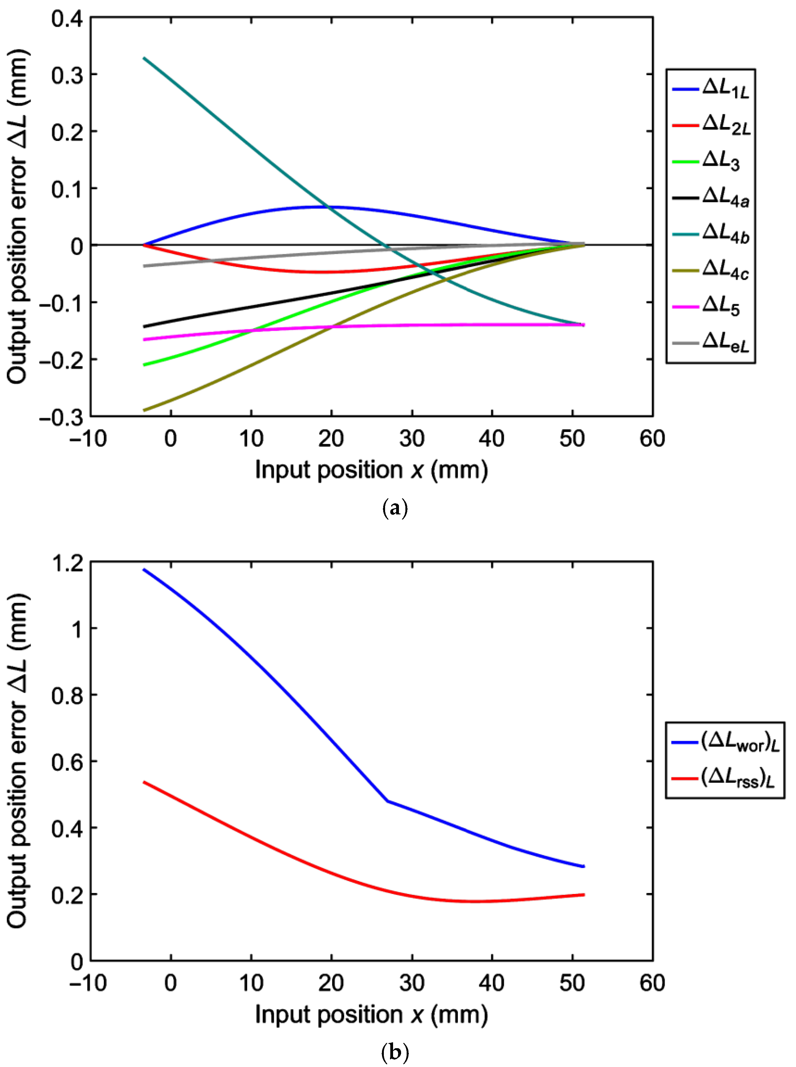
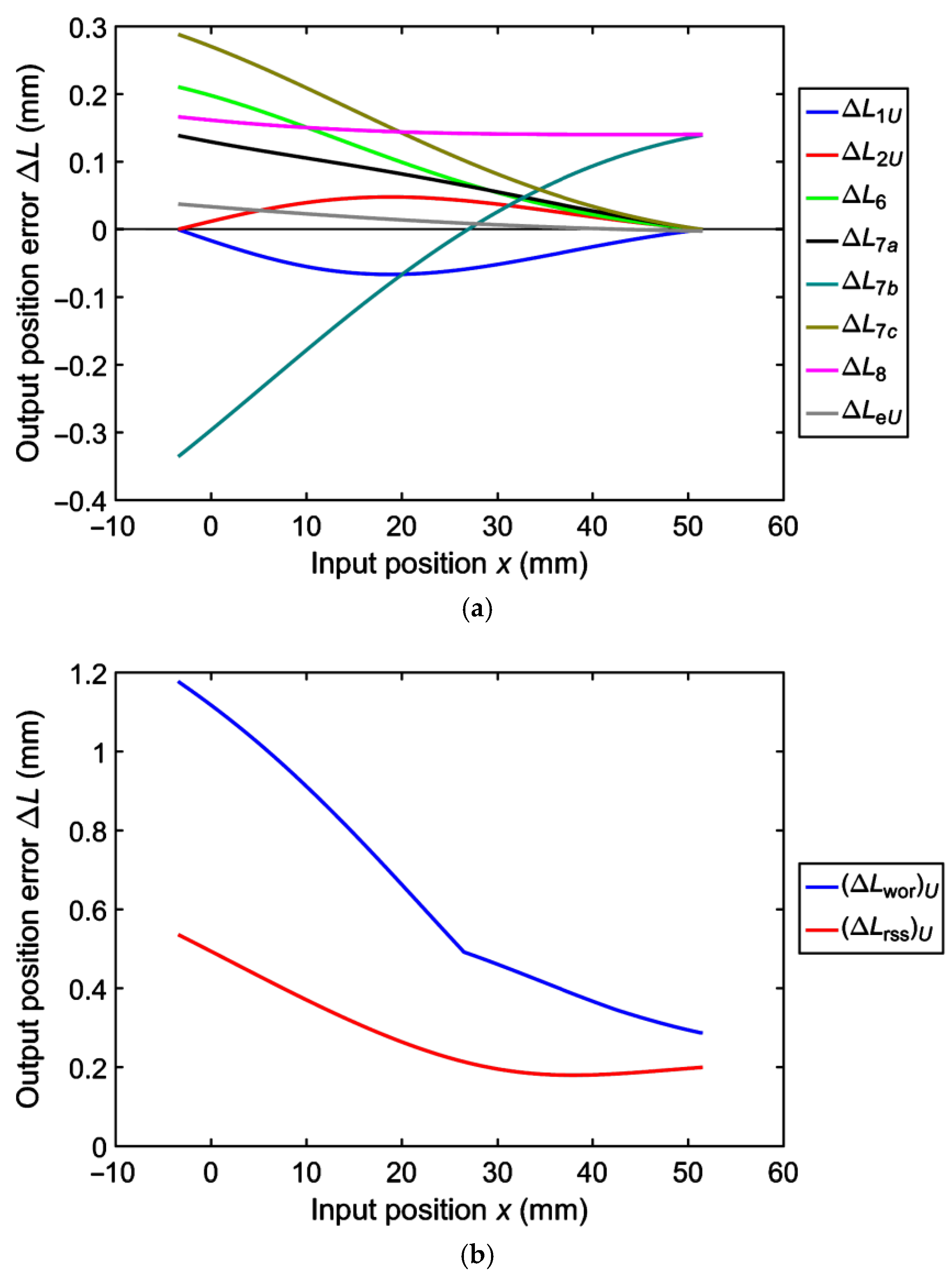
3.3. The Evaluation Indices

From the stochastic viewpoint, the worst-case deviation of the output link of the lower sub-mechanism will be [27,28]
( Δ L wor ) L = | Δ L 1 L | + | Δ L 2 L | + | Δ L 3 | + | Δ L 4 a | + | Δ L 4 b | + | Δ L 4 c | + | Δ L 5 | + | Δ L e L |
in which, (ΔLwor)L represents the worst combinations of the output deviation caused by each link-length error (i.e., dimensional errors or tolerances). The maximum expected deviation of the output link of the lower sub-mechanism will be [27,28]
( Δ L rss ) L = Δ L 1 L 2 + Δ L 2 L 2 + Δ L 3 2 + Δ L 4 a 2 + Δ L 4 b 2 + Δ L 4 c 2 + Δ L 5 2 + Δ L e L 2
in which, (ΔLrss)L is obtained by the widely used root-sum-of-squares (RSS) approach [27,28]. Likewise, the worst-case deviation of the output link of the upper sub-mechanism will be [27,28]
( Δ L wor ) U = | Δ L 1 U | + | Δ L 2 U | + | Δ L 6 | + | Δ L 7 a | + | Δ L 7 b | + | Δ L 7 c | + | Δ L 8 | + | Δ L e U |
Then, the maximum expected deviation of the output link of the upper sub-mechanism will be [27,28]
( Δ L rss ) U = Δ L 1 U 2 + Δ L 2 U 2 + Δ L 6 2 + Δ L 7 a 2 + Δ L 7 b 2 + Δ L 7 c 2 + Δ L 8 2 + Δ L e U 2
Equations (38)–(41) are based on widely used stochastic approaches to obtain four evaluated tolerance ranges ±(ΔLwor)L, ±(ΔLrss)L, ±(ΔLwor)U, and ±(ΔLrss)U of the output link of the lower or upper sub-mechanism, which may be caused by the specified tolerance ranges of the geometric parameters of all link members.
In order to evaluate an extreme condition, when the dimensional errors of all geometric parameters in the lower sub-mechanism are the lower deviations of their specified bilateral tolerance ranges, and those in the upper sub-mechanism are the upper deviations of their specified bilateral tolerance ranges, or vice versa, two evaluation indices can be established as
δ L wor = | ± ( Δ L wor ) U ( Δ L wor ) L | = ( Δ L wor ) U + ( Δ L wor ) L
δ L rss = | ± ( Δ L rss ) U ( Δ L rss ) L | = ( Δ L rss ) U + ( Δ L rss ) L
which are quantitative indices for evaluating the asymmetry between the lower and upper sub-mechanisms. The extreme condition indicates the extent of inconsistency between the horizontal positions of joints F and C of the output link (as shown in Figure 5) that may further lead to excessive wear, large deformations, and even fatigues of link members.

3.4. Case Study

A case study is given to demonstrate the derived analytical equations and the established evaluation indices. Table 1 lists the geometric parameters of a nine-link type double-toggle mold/die clamping mechanism, which are approximately one-third sizes of the clamping system of a real die casting machine. Figure 6 shows the variation trend of the linear position of the output link, L(x), with respect to the input variable x that varies from −3.439 to 51.566 mm. The theoretical stroke of the output link is 45.003 mm. As seen, when x = 51.566 mm, the mechanism is in its toggle position as similar to that shown in Figure 3c. In order to perform the mechanical error analysis, the dimensional errors of all geometric parameters in Table 1 are given based on the ISO tolerance (IT) grades. For the geometric parameters in the lower sub-mechanism, the lower deviations of their specified bilateral tolerance ranges according to the IT grade are given, and for those in the upper sub-mechanism, the upper deviations of their specified bilateral tolerance ranges also according to the IT grade are given.
For this case study, Figure 7 shows the results for the mechanical error analysis of the lower sub-mechanism, in which, a tolerance grade of IT10 is specified to each geometric parameter. In Figure 7a, output error curves induced by each negative dimensional error are presented, and their resultant worst-case and maximum expected deviations, (ΔLwor)L and (ΔLrss)L, are presented in Figure 7b. Similarly, Figure 8 shows the results for the mechanical error analysis of the upper sub-mechanism, in which, a tolerance grade of IT10 is also specified to each geometric parameter. In Figure 8a, output error curves induced by each positive dimensional error are presented, and their resultant worst-case and maximum expected deviations, (ΔLwor)U and (ΔLrss)U, are presented in Figure 8b. As shown in Figure 7a and Figure 8a, when the mechanism is in its toggle position, the dimensional errors of links 4, 5, 7, and 8 will considerably influence the output errors, while those of other links have quite less effects on the output errors. In other words, links 4, 5, 7, and 8, which are the critical link members to form the double-toggle configuration, are also most sensitive to the mechanical error of the output link at that instant. As shown in Figure 7b and Figure 8b, when a tolerance grade of IT10 is specified to each geometric parameter, the stochastic deviations of the output link at the toggle position are about 0.2 to 0.3 mm. Considering that the theoretical stroke of the output link is 45.003 mm, such stochastic deviations imply that the output link will have a degraded positioning accuracy ranging from IT11 to IT13.
Figure 9 shows the variation trends of the evaluation indices at the toggle position with respect to the specified tolerance grades ranging from IT6 to IT12, and their values are also listed in Table 2. As seen, both evaluation indices have nonlinearly increasing trends as the IT grade increases. Therefore, the extent of inconsistency between the horizontal positions of joints F and C of the output link (as shown in Figure 5), as well as the asymmetry of the entire mechanism, will thus increase nonlinearly and may further lead to more and more considerable wear, deformations, and even fatigues of link members. The simulated evaluation indices at the toggle position, as those shown in Figure 9, may be applied in the design stage for a mold/die clamping mechanism to help designers evaluate the most extreme asymmetry between the lower and upper sub-mechanisms caused by the allocated dimensional tolerances of link members.

4. Prototype for Experimental Evaluation

In order to perform the experimental evaluation of mechanical errors in a mold/die clamping mechanism, a prototype is conceptually designed and was actually constructed for experiments.

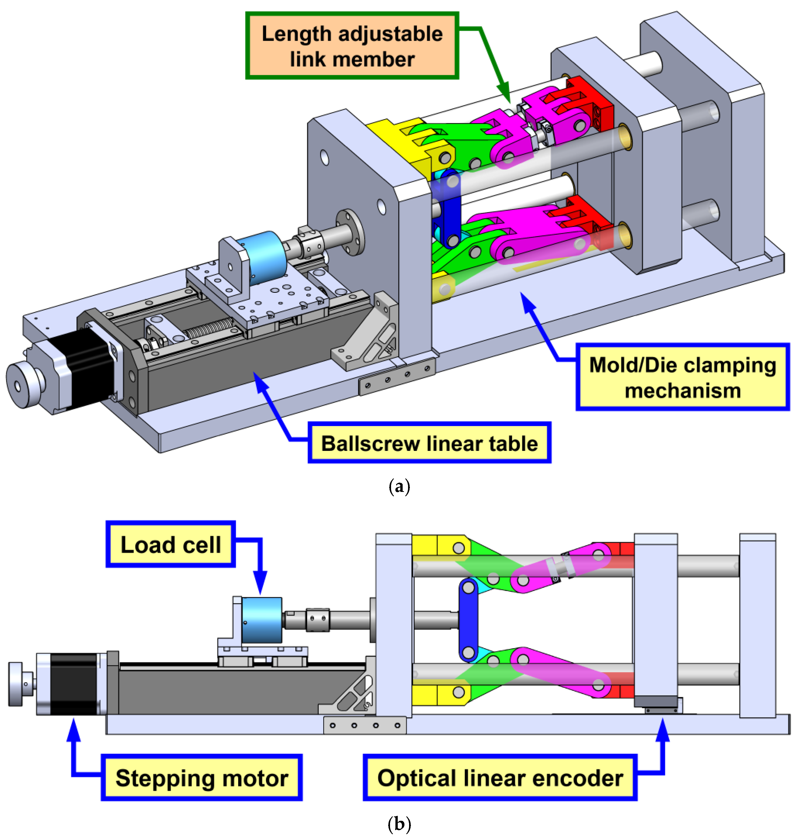
4.1. Conceptual Design

The essential concept of the prototype is based on a mold/die clamping mechanism with adjustable mechanical error(s), and whose operating performance can be detected by installed sensors. Figure 10 shows the computer-aided design (CAD) model of the conceptual design results, in which, the prototype used for mechanical error detection mainly consists of a nine-link type mold/die clamping mechanism driven by a ballscrew linear table. The theoretical geometric parameters of the mold/die clamping mechanism are identical to those for the presented case study (as listed in Table 1), which are approximately one-third sizes of the clamping system of a real die casting machine. Hence, the mold/die clamping mechanism shown in Figure 10 is designed as a desktop hardware model. The ballscrew linear table, instead of a hydraulic cylinder, is thus alternatively applied to drive the mold/die clamping mechanism because of its high positional precision. It can also be noted in Figure 10a that one of the link members in the mold/die clamping mechanism, i.e., link 8 referring to Figure 4 and Figure 5, is a so-called “length adjustable link member” used for adjusting the mechanical error Δr8 (i.e., the length error of link 8). Figure 11 shows the explosive view of the CAD model of the length adjustable link member, in which, this link member mainly consists of a left-half sub member, a right-half sub member, and a compound screw. Two clamping shaft collars attached to each sub member are used to clamp two attached linear shafts, respectively. The compound screw with both left and right hand threads is assembled between the left-half and right-half sub members to form two helical pairs, respectively. The rotational axis of the compound screw is parallel to the two linear shafts. When the compound screw is driven (while the clamping shaft collars are loosened), the two sub members will move together along the rotational axis of the screw in opposite directions, and the length (i.e., the mechanical error) of this link member can thus be fine adjusted. When the mechanical error is fine adjusted to a preferred magnitude, the clamping shaft collars are then fastened to fix the length of this link member. Through such a design concept, a mold/die clamping mechanism with adjustable mechanical error(s) can be realized.
Subsequently, in order to quantitatively detect the operating performance of the mold/die clamping mechanism, two sensors are installed in the prototype, as illustrated in Figure 10b. An optical linear encoder is installed between the output link (the moving platen) and the base plate (of the frame) of the mechanism, which is used to detect the resultant output position caused by mechanical errors. Further, a load cell is installed between the input link of the mechanism and the moving stage of the ballscrew linear table, which is used to detect the required input force for driving the entire mechanism. Therefore, the quantitative influence of mechanical errors on the operating performance of a mold/die clamping mechanism could be evaluated through the presented prototype.

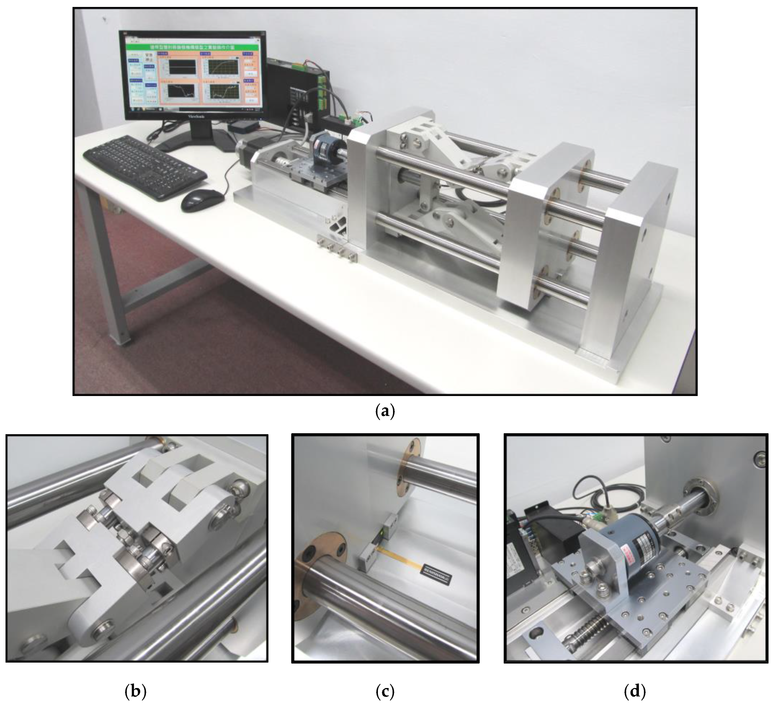
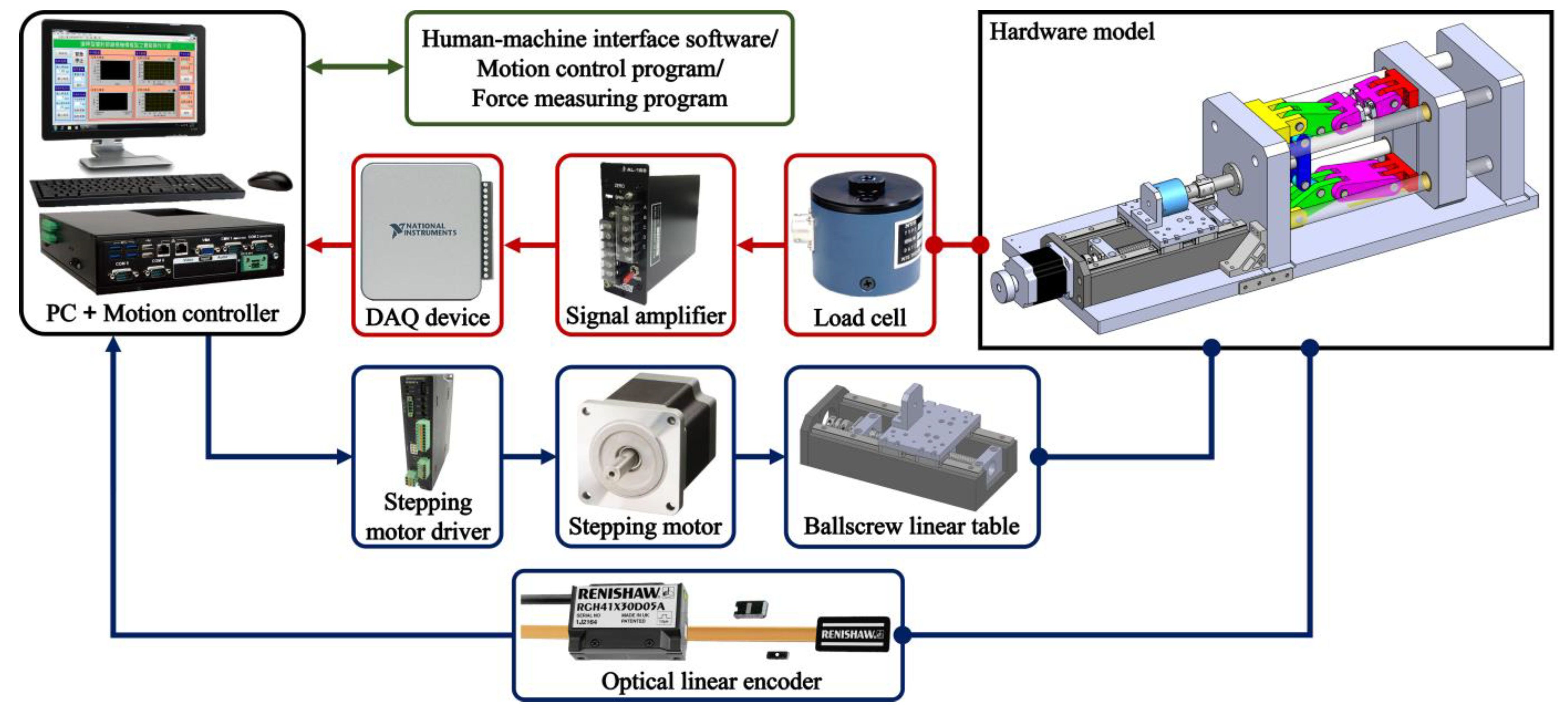
4.2. Hardware Construction and Integration

A hardware model of the prototype was constructed according to the conceptual design presented in Figure 10 and Figure 11. Figure 12 shows the final setup of the constructed prototype, and the overall functional block diagram of the prototype is also shown in Figure 13. For the constructed mold/die clamping mechanism, its base plate, stationary platen, moving platen, tail stock platen, and most parts of link members were all made of JIS A6061 aluminum alloy, while its four tie bars were made of JIS SUJ2 bearing steel. Four flanged oil free bushings (made of bronze) attached to the moving platen were served as linear journal bearings when the moving platen translated relative to the tie bars. A flanged linear bushing attached to the tail stock platen was served as a linear ball bearing when the linear shaft of the input link (made of JIS SUJ2 bearing steel) translated relative to the tail stock platen. The link members were connected by precision pivot pins (made of JIS SUS304 stainless steel) to form all revolute joints with sliding fits [29] in the linkage assembly. For the length adjustable link member, its two linear shafts were made of JIS SUJ2 bearing steel, and its four clamping shaft collars and compound screw were all made of JIS SUS304 stainless steel. The actual lengths of all link members, except the length adjustable one, had been measured by using a Giddings & Lewis Sheffield Measurement Cordax RS-25 coordinate measuring machine (CMM) before they were assembled together. As a result, the length errors of the measured link members were, in average, distributed within a small range of ±0.025 mm.
Subsequently, the ballscrew linear table was driven by a precision ballscrew mechanism (with an accuracy class of C5 and a lead of 5 mm) coupled with an Oriental Motor PKE955BC five-phase stepping motor and an Oriental Motor RKSD507-A five-phase stepping motor driver. The stepping motor module was set to an angular resolution of 25,000 steps/rev, that is, a fine linear displacement of 0.2 μm per step could be achieved. A Renishaw RGH41X/RGS40S optical linear encoder that has a resolution of 1 μm was used to detect the resultant output position (of the moving platen). A Nippon Tokushu Sokki (NTS) LRM-500N load cell, which has a measuring range of ±500 N, coupled with an Algol Instrument AL-168 signal amplifier were used to detect the required input force for driving the entire constructed mechanism.
Furthermore, a Motorcon MDH-1000 motion controller was prepared as a host personal computer (PC) to operate and monitor the entire hardware model. The motion control card embedded in the host PC was used to manipulate the stepping motor and to receive the positional signals detected by the optical linear encoder through its I/O ports. Moreover, the force signals detected by the load cell/signal amplifier were received through a National Instrument (NI) USB-6000 data acquisition (DAQ) device connected to the host PC through its universal serial bus (USB) port. In addition, the required human machine interface software and also motion control and force measuring programs were developed and integrated in the NI LabVIEW environment.

5. Experimental Results and Discussion

Experiments were conducted in order to evaluate the quantitative influence of mechanical errors on the operating performance of the constructed mold/die clamping mechanism. The independent variables for the experiments were the length error of the length adjustable link member (i.e., the mechanical error Δr8) and the driving speed of the input link (i.e., the input speed denoted by v). For comparison purpose, Δr8 was reasonably set to 0.00, 0.25, 0.50, and 0.75 mm, respectively, and v was reasonably set to 5, 15, and 25 mm/s, respectively. Hence, twelve sets of the two independent variables (Δr8, v) were adopted for conducting twelve series of experiments, respectively. For each series of experiments, the input link was driven forwards from an initial position of x = −3.439 mm to a final position of x = 51.566 mm (referring to Figure 6) and then was driven backwards from the final position to the initial position; such a reciprocating motion was repeated for 100 times while the data sets of the continuously varying output positions and input forces were all measured. Therefore, 1200 data sets in total were measured and recorded for further evaluating the operating performance of the constructed mechanism.

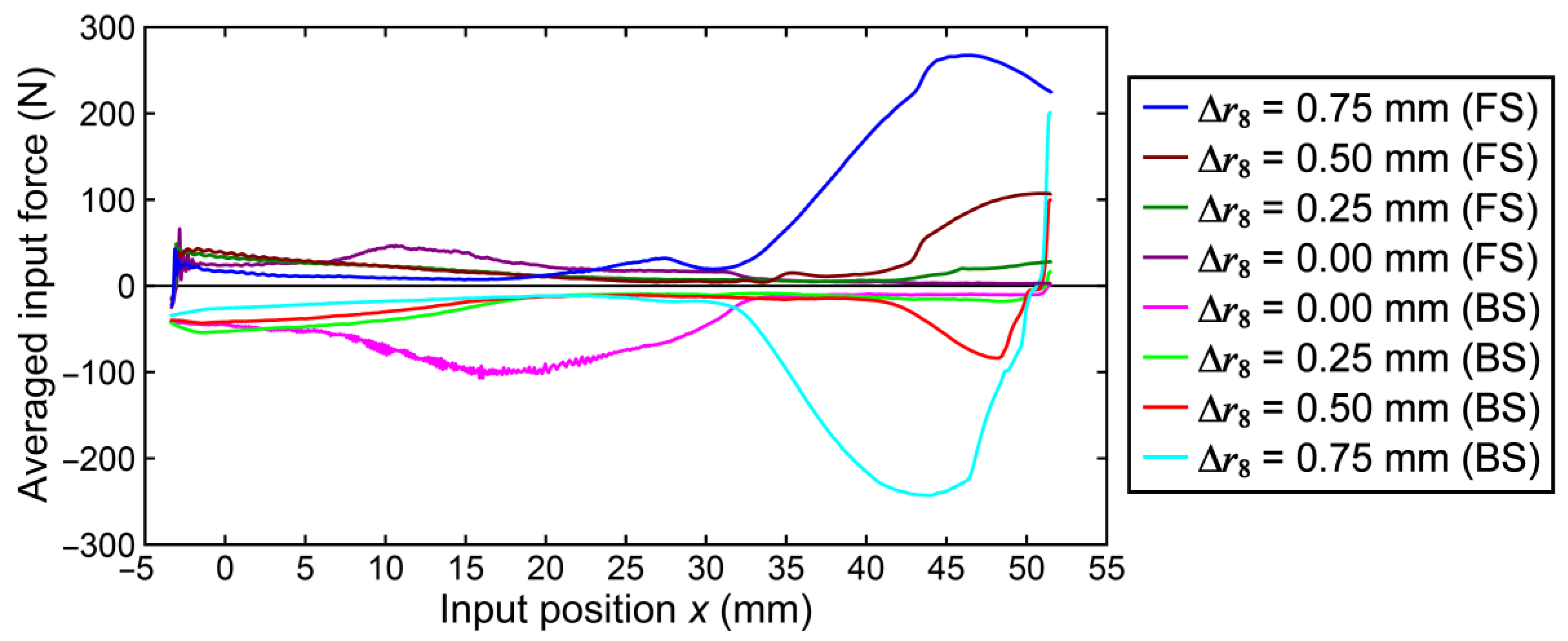
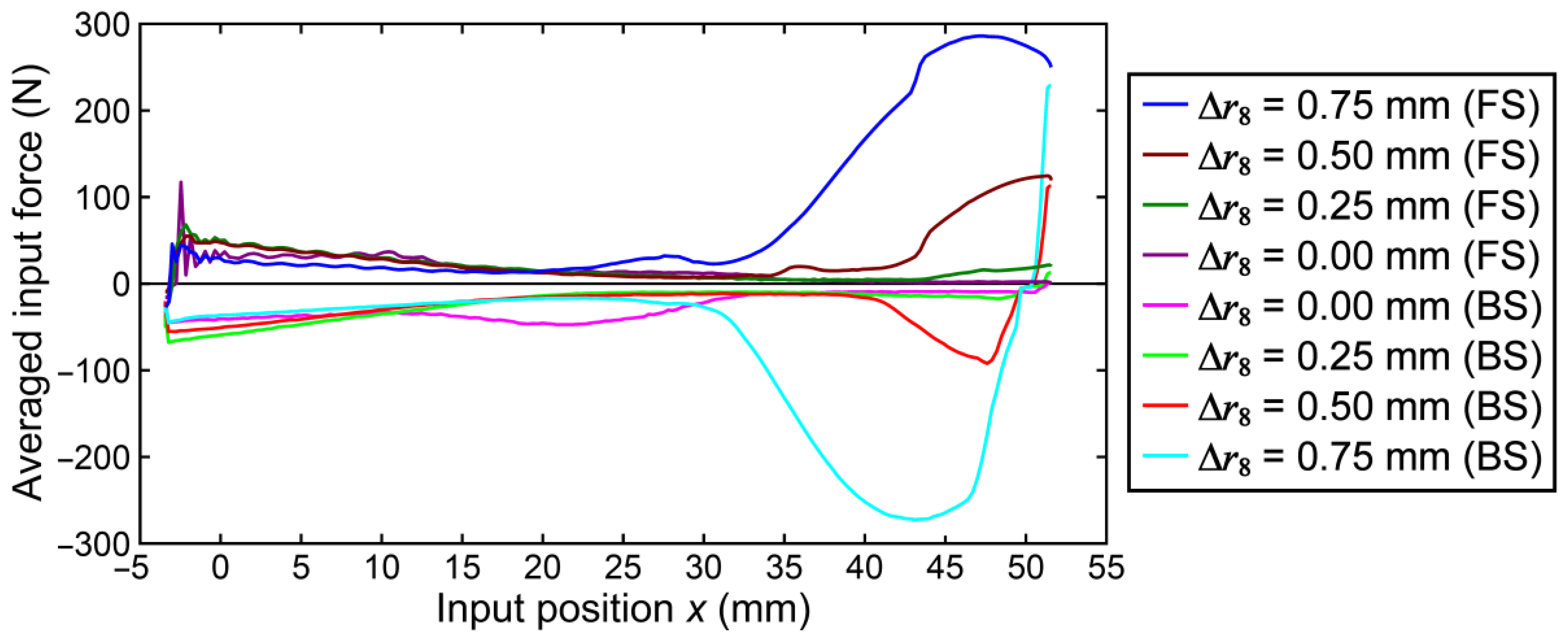
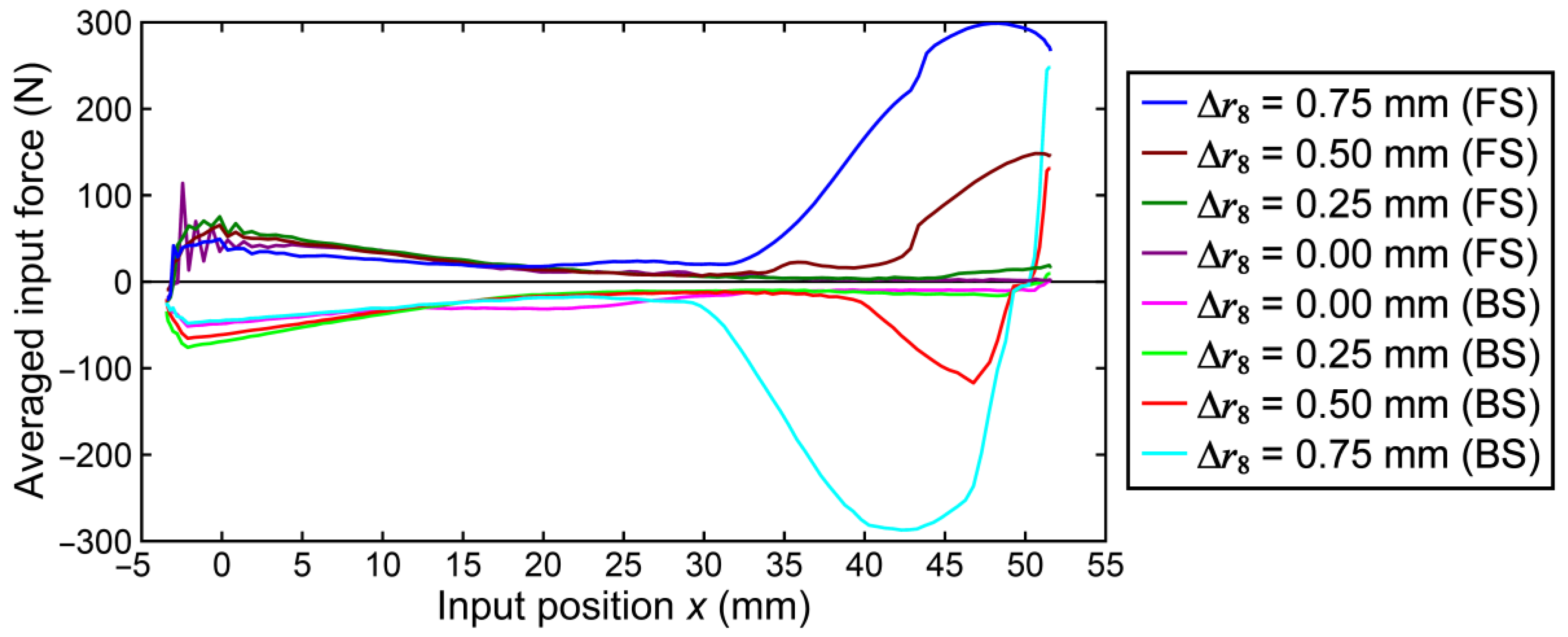
5.1. Experimental Results

Some stochastic results for the experiments that might be of interest are listed in Table 3, Table 4, Table 5, Table 6, Table 7 and Table 8. Table 3, Table 4 and Table 5 list the results for the measured output positions when v = 5, 15, and 25 mm/s, respectively, in which, the stochastic values (i.e., the mean values with their uncertainty ranges evaluated by using the three-standard-deviation-band approach [30]) of the initial stroke position Si (i.e., the relatively initial position of the moving platen measured when x = −3.439 mm), the final stroke position Sf (i.e., the relatively final position of the moving platen measured when x = 51.566 mm), the stroke S (i.e., the overall moving distance of the moving platen measured in one motion cycle), and the stroke error ΔS (when the theoretical stroke is 45.003 mm referring to Figure 6) are presented. Table 6, Table 7 and Table 8 then list the results for the measured input forces when v = 5, 15, and 25 mm/s, respectively, in which, the stochastic values of the extreme and root-mean-square (RMS) values in the forward stroke (FS) FF(max) and FF(rms) (i.e., the maximum and RMS values of the input force in the FS), the extreme and RMS values in the backward stroke (BS) FB(min) and FB(rms) (i.e., the minimum and RMS values of the input force in the BS), and also the measured input forces at the toggle position (when x = 51.566 mm in the FS) FTP are presented. In addition, the averaged input force curves obtained when v = 5, 15, and 25 mm/s, respectively, are shown in Figure 14, Figure 15 and Figure 16, in which each curve represents an averaged varying trend evaluated from 100 measured data sets.
From the stochastic results listed in Table 3, Table 4 and Table 5, it can be observed that the mean values of the initial and final stroke positions, Si and Sf, all slightly deviated from their theoretical values 0.000 and 45.003 mm, respectively. For all of the three input speeds, the positional deviations for the mean values of Si ranged between −0.011 and −0.180 mm, and those for the mean values of Sf ranged between 0.269 and 0.466 mm; while the mean values of the resultant stroke errors, ΔS, ranged between 0.383 and 0.561 mm. The varying trends of the positional deviations were not quite proportional to the increased magnitudes of Δr8 and v. Such positional uncertainties should be mainly caused by clearances in revolute joints of the constructed mechanism, since such clearances caused by sliding fits [29] could not be completely eliminated and would result in a similar effect of “backlash” when producing reciprocating motions. However, the varying trends of the resultant stroke errors were approximately proportional to the increased magnitudes of Δr8 and v. Therefore, clearances in revolute joints should have much effect on influencing the positional uncertainties, but less effect on influencing the resultant stroke errors.
From the stochastic results listed in Table 6, Table 7 and Table 8, it is found that when v = 5 and 15 mm/s, the mean values of FF(max) and FF(rms) in the FS and those of FB(min) and FB(rms) in the BS were with the smallest magnitudes as Δr8 = 0.25 mm, and were with the largest magnitudes as Δr8 = 0.75 mm. When v = 25 mm/s, the mean values of FF(max) and FB(rms) were with the smallest magnitudes as Δr8 = 0.25 mm, and those of FF(rms) and FB(min) were with the smallest magnitudes as Δr8 = 0.00 mm, while the four force terms were with the largest magnitudes as Δr8 = 0.75 mm. When Δr8 = 0.00 mm was set, the constructed mechanism could still not achieve an ideally symmetric configuration because of the influence of small mechanical errors of other link members. When Δr8 = 0.25 mm was set, the extent of asymmetry of the constructed mechanism might be reduced instead, which might further lead to the smallest magnitudes for most force terms. It is also noted that for all of the three input speeds, the mean values of FTP had nonlinearly increasing trends as the mechanical error Δr8 increased; such situations can also be observed in Figure 14, Figure 15 and Figure 16. Evidently, when Δr8 was not set to zero, the mean values of FTP were not closed to zero. In other words, when the mechanical error Δr8 existed in the constructed mechanism, this mechanism might not achieve a very large MA in the toggle position. The MA of the constructed mechanism in the toggle position would be considerably reduced with the increased mechanical error Δr8.
In addition, the averaged input force curves shown in Figure 14, Figure 15 and Figure 16 reveal that the input speed v could influence their magnitudes to a certain extent, but had relatively less effects on influencing their overall varying trends as compared with the influence caused by the mechanical error Δr8. When Δr8 = 0.50 or 0.75 mm was set, the extent of asymmetry of the constructed mechanism would be considerably increased, and the induced force curves also drastically increased during the end portion of the FS (approximately when x ≥ 35 mm). As a result, a larger magnitude of the mechanical error Δr8 would lead to a larger driving resistance and a worse toggle effect.

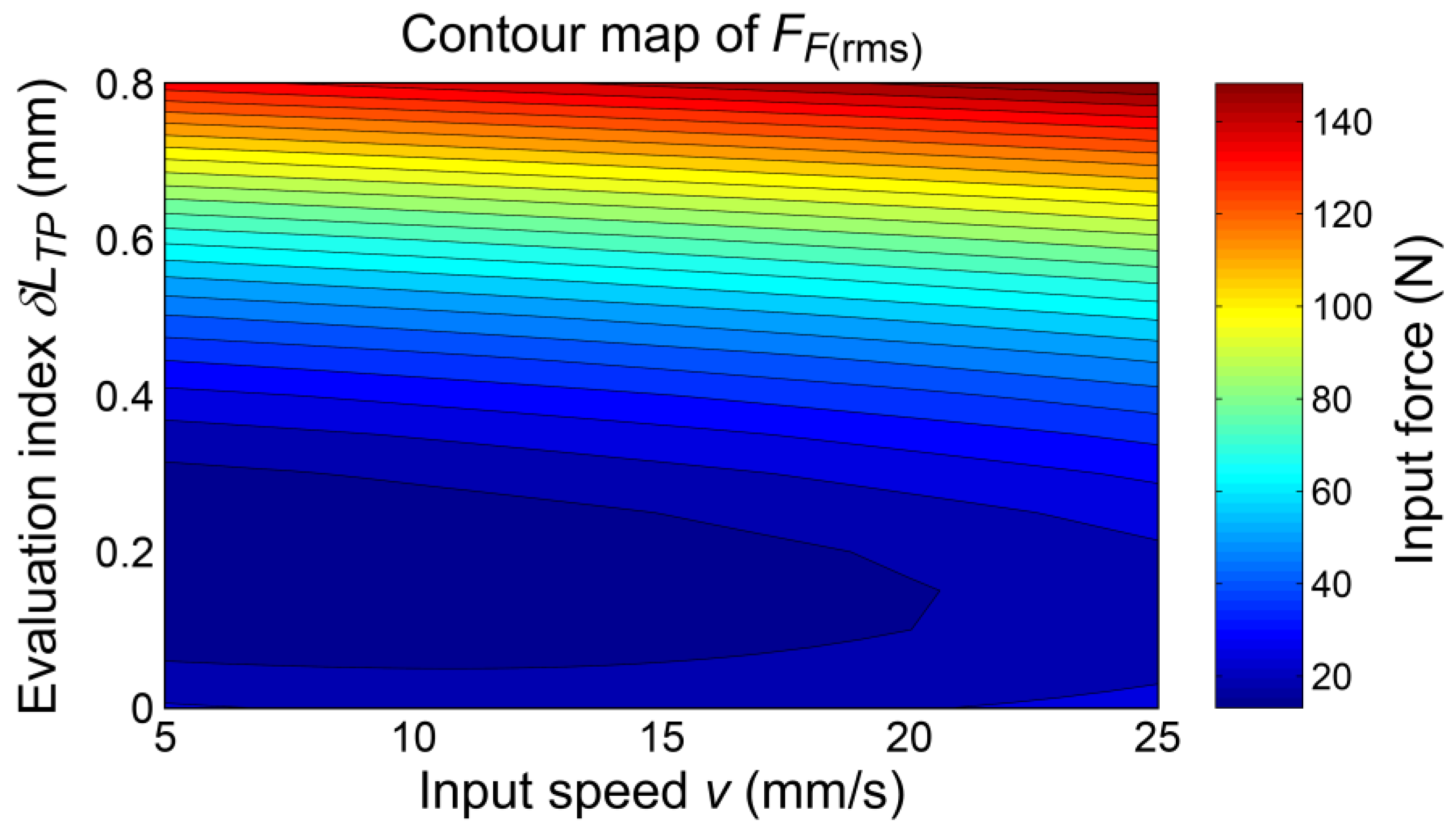
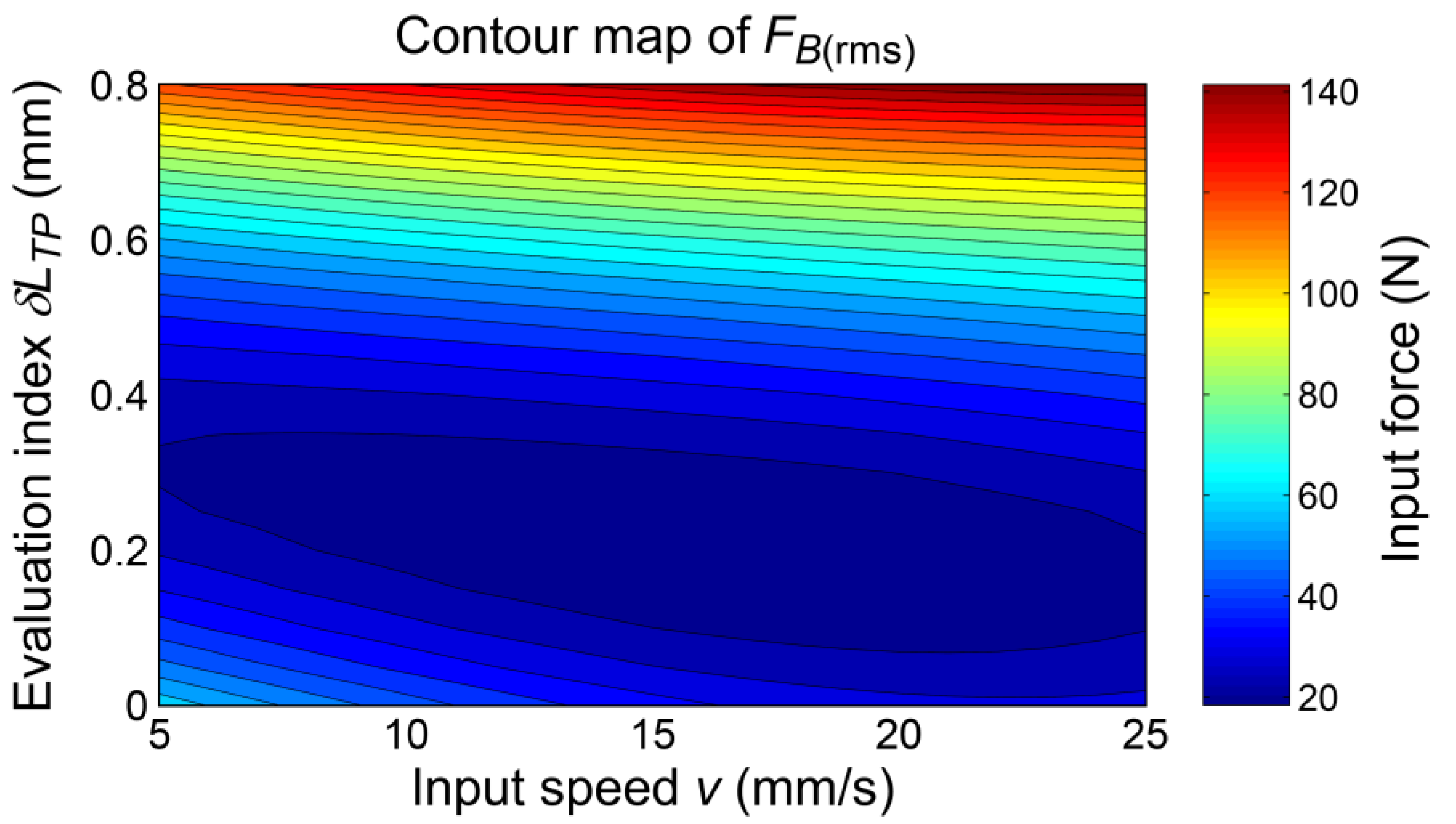
5.2. Response Surface Modelling

According to the experimental results, the stroke error ΔS, the RMS values of the input force FF(rms) and FB(rms), and the input force at the toggle position FTP can be considered as quantitative indices for evaluating the operating performance of the constructed mold/die clamping mechanism. To this end, statistical regression models for estimating the four quantitative indices, ΔS, FF(rms), FB(rms), and FTP, caused by the two independent variables (Δr8, v) must be established. By using the well-known response surface methodology (RSM) [31,32,33,34,35,36] with a modified cubic model [36] and the mean values of the four terms listed in Table 3, Table 4, Table 5, Table 6, Table 7 and Table 8, four approximate functions with respect to Δr8 and v can be obtained as
Δ S ( Δ r 8 , v ) 0.3723 + 0.0046 v 0.1098 Δ r 8 + 0.0257 v Δ r 8 0.0000794 v 2 + 0.1225 Δ r 8 2 0.000664 v 2 Δ r 8 0.0028 v Δ r 8 2
F F ( rms ) ( Δ r 8 , v ) 27.1115 0.6196 v 138.5438 Δ r 8 + 3.3977 v Δ r 8 + 0.0225 v 2 + 335.6090 Δ r 8 2 0.0269 v 2 Δ r 8 1.8854 v Δ r 8 2  
F B ( rms ) ( Δ r 8 , v ) 81.7199 4.6574 v 311.1964 Δ r 8 + 13.5623 v Δ r 8 + 0.1032 v 2 + 429.60 Δ r 8 2 0.1994 v 2 Δ r 8 5.0464 v Δ r 8 2
F T P ( Δ r 8 , v ) 7.6677 1.0773 v 1.2923 Δ r 8 + 3.5459 v Δ r 8 + 0.0240 v 2 + 361.5857 Δ r 8 2 0.0587 v 2 Δ r 8 + 2.5694 v Δ r 8 2
The norms of residuals of the four approximate models are reasonably small. Subsequently, according to Equation (36), the output error of the upper sub-mechanism (as shown in Figure 5) induced only by Δr8 is
Δ L 8 = Δ r 8 sec θ 8
When Δr8 ≥ 0 and −90° < θ8 < +90° are considered, and the mechanical errors of other link members are ignored, then from Equations (38)–(41), (ΔLwor)L = (ΔLrss)L = 0 and (ΔLwor)U = (ΔLrss)U = ΔL8 may be obtained. Thus, the evaluation indices shown in Equations (42) and (43) are
δ L wor = δ L rss = Δ L 8
If only the toggle position is considered, a simplified evaluation index termed δLTP can be defined as
δ L T P = Δ L 8 ( x T P ) = Δ r 8 sec θ 8 ( x T P )
in which, xTP is the position of the input link when the mold/die clamping mechanism is in the toggle position. For the presented case study and the constructed prototype, xTP is 51.566 mm and θ8(xTP) is −2.729°. Hence, from Equation (50), the mechanical error Δr8 can be represented as
Δ r 8 = δ L T P cos θ 8 ( x T P ) 0.998865 δ L T P
By substituting Equation (51) into Equations (44)–(47), four approximate functions with respect to δLTP and v can be obtained as
Δ S ( δ L T P , v ) 0.3723 + 0.0046 v 0.1097 δ L T P + 0.0256 v δ L T P 0.0000794 v 2 + 0.1222 δ L T P 2 0.000663 v 2 δ L T P 0.0027 v δ L T P 2
F F ( rms ) ( δ L T P , v ) 27.1115 0.6196 v 138.3866 δ L T P + 3.3939 v δ L T P + 0.0225 v 2 + 334.8480 δ L T P 2 0.0269 v 2 δ L T P 1.8811 v δ L T P 2
F B ( rms ) ( δ L T P , v ) 81.7199 4.6574 v 310.8434 δ L T P + 13.5469 v δ L T P + 0.1032 v 2 + 428.6259 δ L T P 2 0.1992 v 2 δ L T P 5.0350 v δ L T P 2
F T P ( δ L T P , v ) 7.6677 1.0773 v 1.2908 δ L T P + 3.5419 v δ L T P + 0.0240 v 2 + 360.7657 δ L T P 2 0.0587 v 2 δ L T P + 2.5636 v δ L T P 2
The response surface contour maps according to Equations (52)–(55) are depicted in Figure 17, Figure 18, Figure 19 and Figure 20, respectively. The four approximate functions ΔS(δLTP, v), FF(rms)(δLTP, v), FB(rms)(δLTP, v), and FTP(δLTP, v) can be used as quantitative indices for evaluating the operating performance of the constructed mold/die clamping mechanism caused by both the extents of its asymmetry and input speed. As can be observed, the varying trend of function ΔS(δLTP, v) was more nonlinear than those of the other three functions. The magnitude of the stroke error ΔS would be influenced by both the extends of v and δLTP, while those of the three input force-related indices FF(rms), FB(rms), and FTP would be mainly dominated by the extend of δLTP. According to the response surface modelling results, conservative ranges of 10 < v < 20 mm/s and 0.1 < δLTP < 0.4 mm could be suggested for benefiting the constructed mold/die clamping mechanism with better operating performance. The presented response surface contour maps, as those shown in Figure 17, Figure 18, Figure 19 and Figure 20, may be applied to predict or monitor the operating performance of the mold/die clamping mechanism in an actual injection molding machine or die casting machine through actually measured data.

5.3. Discussion

The presented prototype, based on the mechanical error detection, had been applied to evaluate the operating performance of the constructed mold/die clamping mechanism. The experiments and response surface modelling based on the presented prototype demonstrate a simulated situation for the on-line mechanical error detection of the mold/die clamping mechanism in an actual injection molding machine or die casting machine. In the era of industry 4.0, the presented prototype could provide an applicable framework of on-line data collection for injection molding machines and die casting machines. The on-line data of the resultant output positions (of the moving platen) caused by mechanical errors and of the required input forces for driving the entire mechanism could be collected for a long term. The collected big data could be further dealt with through the established evaluation indices in combining with the response surface modelling or the artificial neural network modelling [37]. The obtained mathematical models would be applicable to on-line monitor the operating performance and detect/diagnose the abnormal conditions of the clamping systems of injection molding machines and die casting machines. Therefore, the presented prototype, based on the mechanical error detection, should be helpful to improve conventional injection molding machines and die casting machines to meet partial requirements for realizing the machine layer in a smart factory framework. Such applications for promoting injection molding and die casting processes in the era of industry 4.0 could be possible future work.

6. Conclusions

The theoretical analysis of mechanical errors in nine-link type double-toggle mold/die clamping mechanisms, as well as the design and construction of a prototype for performing the experimental evaluation of mechanical errors, have been presented in this paper.
The kinematic error equations of the output link (i.e., the moving platen) caused by dimensional errors (or tolerances) of link members have been derived analytically. Two evaluation indices based on the asymmetry of the mechanism caused by mechanical errors have also been established. A case study has been given to demonstrate the derived analytical equations and the established evaluation indices. It shows that the critical link members to form the double-toggle configuration are also most sensitive to the mechanical error of the output link at that instant. When the dimensional errors of all geometric parameters are specified according to an IT grade, the stroke of the output link will stochastically have a degraded positioning accuracy. The evaluation indices, as well as the asymmetry of the entire mechanism, have nonlinearly increasing trends as the IT grade increases, and may further lead to more and more considerable wear, deformations, and even fatigues of link members.
A hardware model of the prototype had been constructed. Experiments had been conducted for evaluating the quantitative influence of mechanical errors on the operating performance of the constructed mold/die clamping mechanism. The experimental results showed that the stroke errors of the output link would be proportionally influenced by both the increased magnitudes of the mechanical error and the input speed. Further, the MA of the constructed mechanism in the toggle position would be considerably reduced with the increased mechanical error. Thus, a larger magnitude of mechanical error would lead to a larger driving resistance and a worse toggle effect. According to the response surface modelling results, conservative ranges could be suggested for benefiting the constructed mold/die clamping mechanism with better operating performance.
The presented research results will be helpful in the tolerance analysis (and design) and mechanical error detection of nine-link type double-toggle mold/die clamping mechanisms. The presented prototype could also provide an applicable framework of on-line data collection for injection molding machines and die casting machines, which should be helpful to improve conventional injection molding machines and die casting machines to meet partial requirements of the machine layer in a smart factory framework for the era of industry 4.0.

Author Contributions

Conceptualization, W.-T.C.; methodology, W.-T.C.; software, W.-I.L.; validation, W.-T.C., W.-I.L., and K.-L.H.; formal analysis, W.-T.C. and K.-L.H.; investigation, W.-T.C. and W.-I.L.; resources, W.-T.C.; data curation, W.-T.C. and W.-I.L.; writing—original draft preparation, W.-T.C. and K.-L.H.; visualization, W.-T.C. and W.-I.L.; funding acquisition, W.-T.C. and K.-L.H. All authors have read and agreed to the published version of the manuscript.

Funding

This research was funded by Ministry of Science and Technology of Taiwan, under grant numbers MOST-105-2221-E-019-028 and MOST-108-2636-E-002-012-MY3.

Institutional Review Board Statement

Not applicable.

Informed Consent Statement

Not applicable.

Data Availability Statement

The data presented in this study are available from the corresponding author, W.-T. Chang, upon reasonable request.

Acknowledgments

The third author is grateful for the substantial support of National Taiwan University. Most importantly, the Young Scholar Fellowship Program supported by the Ministry of Science and Technology of Taiwan encourages the third author to fearlessly devote to his research.

Conflicts of Interest

The authors declare no conflict of interest.

Appendix A

According to Equation (18), the partial derivatives appearing in Equation (19) can be further expressed as follows
F L r 1 L = F L θ 4 · θ 4 r 1 L
F L r 2 L = F L θ 4 · θ 4 r 2 L
F L r 3 = F L θ 4 · θ 4 r 3
F L r 4 a = F L θ 4 · θ 4 r 4 a
F L r 4 b = F L θ 4 · θ 4 r 4 b + cos θ 4 + sin θ 4 tan θ 5
F L r 4 c = F L θ 4 · θ 4 r 4 c
F L r 5 = 1 cos θ 5
F L e L = tan θ 5
F L L L = 1
where, in Equations (A1)–(A6), the partial derivative ∂FL/∂θ4 can be derived and expressed as
F L θ 4 = r 4 b ( cos θ 4 tan θ 5 sin θ 4 )
and, the remaining partial derivatives can be derived and expressed as
θ 4 r 1 L = sin γ 1 L cos γ 1 L cot γ 2 L l L + cos γ 1 L r 4 a sin γ 2 L
θ 4 r 2 L = cos γ 1 L cot γ 2 L sin γ 1 L l L cos γ 1 L r 4 a sin γ 2 L
θ 4 r 3 = r 3 l L r 4 a sin γ 2 L
θ 4 r 4 a = r 4 a r 4 b cos α 4 r 4 a r 4 b sin α 4 + r 4 a l L cos γ 2 L r 4 a l L sin γ 2 L
θ 4 r 4 b = r 4 b r 4 a cos α 4 r 4 a r 4 b sin α 4
θ 4 r 4 c = r 4 c r 4 a r 4 b sin α 4
With the use of the partial derivatives derived in Equations (A1)–(A16), the kinematic error equations of the output link are accordingly derived as those shown in Equations (20)–(27).

Appendix B

According to Equation (28), the partial derivatives appearing in Equation (29) can be further expressed as follows
F U r 1 U = F U θ 7 · θ 7 r 1 U
F U r 2 U = F U θ 7 · θ 7 r 2 U
F U r 6 = F U θ 7 · θ 7 r 6
F U r 7 a = F U θ 7 · θ 7 r 7 a
F U r 7 b = F U θ 7 · θ 7 r 7 b + cos θ 7 + sin θ 7 tan θ 8
F U r 7 c = F U θ 7 · θ 7 r 7 c
F U r 8 = 1 cos θ 8
F U e U = tan θ 8
F U L U = 1
where, in Equations (A17)–(A22), the partial derivative ∂FU/∂θ7 can be derived and expressed as
F U θ 7 = r 7 b ( cos θ 7 tan θ 8 sin θ 7 )
and, the remaining partial derivatives can be derived and expressed as
θ 7 r 1 U = sin γ 1 U cos γ 1 U cot γ 2 U l U cos γ 1 U r 7 a sin γ 2 U
θ 7 r 2 U = cos γ 1 U cot γ 2 U sin γ 1 U l U + cos γ 1 U r 7 a sin γ 2 U
θ 7 r 6 = r 6 l U r 7 a sin γ 2 U
θ 7 r 7 a = r 7 a r 7 b cos α 7 r 7 a r 7 b sin α 7 r 7 a l U cos γ 2 U r 7 a l U sin γ 2 U
θ 7 r 7 b = r 7 b r 7 a cos α 7 r 7 a r 7 b sin α 7
θ 7 r 7 c = r 7 c r 7 a r 7 b sin α 7
With the use of the partial derivatives derived in Equations (A17)–(A32), the kinematic error equations of the output link are accordingly derived as those shown in Equations (30)–(37).

References

  1. Johannaber, F. Injection Molding Machines—A User’s Guide, 3rd ed.; Hanser/Gardner Publications: Cincinnati, OH, USA, 1994. [Google Scholar]
  2. Frantz, C.E. Mold-Separating Device. U.S. Patent 1880380, 4 October 1932. [Google Scholar]
  3. Yan, H.S. Mechanisms—Theory and Applications; McGraw-Hill Education (Asia): Singapore, 2016; pp. 19–30, 50–51, 69–70, 124–125. [Google Scholar]
  4. Fung, R.F.; Hwang, C.C.; Hwang, C.S.; Chen, W.P. Inverse dynamics of a toggle mechanism. Comput. Struct. 1997, 63, 91–99. [Google Scholar] [CrossRef]
  5. Lin, W.Y.; Hsiao, K.M. Investigation of the friction effect at pin joints for the five-point double-toggle clamping mechanisms of injection molding machines. Int. J. Mech. Sci. 2003, 45, 1913–1927. [Google Scholar] [CrossRef]
  6. Lin, W.Y.; Hsiao, K.M. Study on improvements of the five-point double-toggle mould clamping mechanism. Proc. Inst. Mech. Eng. Part C J. Mech. Eng. Sci. 2004, 218, 761–774. [Google Scholar] [CrossRef]
  7. Lin, W.Y.; Shen, C.L.; Hsiao, K.M. A case study of the five-point double-toggle mould clamping mechanism. Proc. Inst. Mech. Eng. Part C J. Mech. Eng. Sci. 2006, 220, 527–535. [Google Scholar] [CrossRef]
  8. Huang, M.S.; Lin, T.Y.; Fung, R.F. Key design parameters and optimal design of a five-point double-toggle clamping mechanism. Appl. Math. Model 2011, 35, 4304–4320. [Google Scholar] [CrossRef]
  9. Chiang, M.H.; Yang, F.L.; Chen, Y.N.; Yeh, Y.P. Integrated control of clamping force and energy-saving in hydraulic injection moulding machines using decoupling fuzzy sliding-mode control. Int. J. Adv. Manuf. Technol. 2005, 27, 53–62. [Google Scholar] [CrossRef]
  10. Rao, B.; Zhou, H.; Ouyang, H.; Wan, Y.; Zhang, Y.; Wu, J. Study on the clamping force measurement and partial load regulation technology of injection molding machine. CIRP J. Manuf. Sci. Technol. 2017, 19, 19–24. [Google Scholar] [CrossRef]
  11. Huang, M.S.; Lin, C.Y. A novel clamping force searching method based on sensing tie-bar elongation for injection molding. Int. J. Heat Mass Tran. 2017, 109, 223–230. [Google Scholar] [CrossRef]
  12. Huang, M.S.; Nian, S.C.; Chen, J.Y.; Lin, C.Y. Influence of clamping force on tie-bar elongation, mold separation, and part dimensions in injection molding. Precis. Eng. 2018, 51, 647–658. [Google Scholar] [CrossRef]
  13. Zhao, Y.; Zhao, P.; Zhang, J.; Huang, J.; Xia, N.; Fu, J. On-line measurement of clamping force for injection molding machine using ultrasonic technology. Ultrasonics 2019, 91, 170–179. [Google Scholar] [CrossRef]
  14. Hartenberg, R.S.; Denavit, J. Kinematic Synthesis of Linkages; McGraw-Hill: New York, NY, USA, 1964; pp. 315–320. [Google Scholar]
  15. Garrett, R.E.; Hall, A.S. Effect of tolerance and clearance in linkage design. J. Eng. Ind. 1969, 9, 198–202. [Google Scholar] [CrossRef]
  16. Dhande, S.G.; Chakraborty, J. Analysis and synthesis of mechanical error in linkages—a stochastic approach. J. Eng. Ind. 1973, 95, 672–676. [Google Scholar] [CrossRef]
  17. Lakshminarayan, K.; Narayanamurthi, R.G. On the analysis of the effect of tolerances in linkages. J. Mech. 1971, 6, 59–67. [Google Scholar] [CrossRef]
  18. Choubey, M.; Rao, A.C. Synthesizing linkages with minimal structural and mechanical error based upon tolerance allocation. Mech. Mach. Theory 1982, 17, 91–97. [Google Scholar] [CrossRef]
  19. Sukhija, R.P.; Rao, A.C. Mechanical error synthesis of path generating mechanism using reliability index. Trans. Can. Soc. Mech. Eng. 1986, 10, 85–90. [Google Scholar] [CrossRef]
  20. Chatterjee, G.B.; Mallik, A.K. Mechanical error of a four-bar linkage coupler curve. Mech. Mach. Theory 1987, 22, 85–88. [Google Scholar] [CrossRef]
  21. Mallik, A.K.; Dhande, S.G. Analysis and synthesis of mechanical error in path-generating linkages using a stochastic approach. Mech. Mach. Theory 1987, 22, 115–123. [Google Scholar] [CrossRef]
  22. Flores, P. A methodology for quantifying the kinematic position errors due to manufacturing and assembly tolerances. J. Mech. Eng. 2011, 57, 457–467. [Google Scholar] [CrossRef]
  23. Mutawe, S.; Al-Smadi, Y.M.; Sodhi, R.S. Planar Four-bar Path Generation Considering Worst Case Joint Tolerances. In Proceedings of the World Congress on Engineering and Computer Science, San Francisco, CA, USA, 19–21 October 2011. [Google Scholar]
  24. Pavlović, N.D. Analysis of Mechanical Error In Quick-Return Shaper Mechanism. In Proceedings of the 12th IFToMM World Congress, Besançon, France, 18–21 June 2007. [Google Scholar]
  25. Oprisan, C.; Leohchi, D. Methodology for analysis of the influence of the mechanical errors and of the clearances on the precision of Watt and Stephenson mechanisms. Lat. Am. J. Solids Struct. 2007, 4, 1–17. [Google Scholar]
  26. Ting, K.L.; Long, Y. Performance quality and tolerance sensitivity of mechanisms. Trans. ASME J. Mech. Des. 1996, 118, 144–150. [Google Scholar] [CrossRef]
  27. Creveling, C.M. Tolerance Design—A Handbook for Developing Optimal Specifications; Addison-Wesley: Reading, MA, USA, 1997. [Google Scholar]
  28. Chang, W.T.; Wu, L.I. Tolerance analysis and synthesis of cam-modulated linkages. Math. Comput. Model. 2013, 57, 641–660. [Google Scholar] [CrossRef]
  29. Shigley, J.E.; Mischke, C.R. Mechanical Engineering Design, 5th ed.; McGraw-Hill: New York, NY, USA, 1989; pp. 157–163. [Google Scholar]
  30. Beckwith, T.G.; Marangoni, R.D.; Lienhard, J.H. Mechanical Measurements, 5th ed.; Pearson Education Taiwan Ltd.: Taipei, Taiwan, 2004; pp. 45–125. [Google Scholar]
  31. The MathWorks Inc. MATLAB Statistics Toolbox User’s Guide—Version 2; The MathWorks Inc.: Natick, MA, USA, 1999. [Google Scholar]
  32. Lee, E.S.; Hwang, S.C.; Lee, J.T.; Won, J.K. A study on the characteristic of parameters by the response surface method in final wafer polishing. Int. J. Precis. Eng. Manuf. 2009, 10, 25–30. [Google Scholar] [CrossRef]
  33. Yoon, H.S.; Wu, R.; Lee, T.M.; Ahn, S.H. Geometric optimization of micro drills using Taguchi methods and response surface methodology. Int. J. Precis. Eng. Manuf. 2011, 12, 871–875. [Google Scholar] [CrossRef]
  34. Zębala, W.; Kowalczyk, R. Estimating the effect of cutting data on surface roughness and cutting force during WC-Co turning with PCD tool using Taguchi design and ANOVA analysis. Int. J. Adv. Manuf. Technol. 2015, 77, 2241–2256. [Google Scholar] [CrossRef]
  35. Aggarwal, V.; Khangura, S.S.; Garg, R.K. Parametric modeling and optimization for wire electrical discharge machining of Inconel 718 using response surface methodology. Int. J. Adv. Manuf. Technol. 2015, 79, 31–47. [Google Scholar] [CrossRef]
  36. Chang, W.T.; Chen, L.C. Design and experimental evaluation of a circular saw blade with self-clamped cutting inserts. Int. J. Adv. Manuf. Technol. 2016, 83, 365–379. [Google Scholar] [CrossRef]
  37. Haykin, S. Neural Networks—A Comprehensive Foundation, 2nd ed.; Prentice-Hall: Upper Saddle River, NJ, USA, 1999. [Google Scholar]
Figure 1. Perspective view of a nine-link type double-toggle mold/die clamping mechanism.
Applsci 11 00832 g001
Figure 2. Perspective sectional view of a nine-link type double-toggle mold/die clamping mechanism.
Applsci 11 00832 g002
Figure 3. Configurations of a nine-link type double-toggle mold/die clamping mechanism: (a) initial position, (b) intermediate position, and (c) toggle position.
Applsci 11 00832 g003
Figure 4. Structural diagram of a nine-link type double-toggle mold/die clamping mechanism.
Applsci 11 00832 g004
Figure 5. Two sub-mechanisms divided from the nine-link type double-toggle mold/die clamping mechanism.
Applsci 11 00832 g005
Figure 6. Variation trend of the linear position of the output link with respect to the input variable.
Applsci 11 00832 g006
Figure 7. Results for the mechanical error analysis of the lower sub-mechanism: (a) output error curves induced by negative dimensional errors, and (b) the resultant worst-case and maximum expected deviations.
Applsci 11 00832 g007
Figure 8. Results for the mechanical error analysis of the upper sub-mechanism: (a) output error curves induced by positive dimensional errors, and (b) the resultant worst-case and maximum expected deviations.
Applsci 11 00832 g008
Figure 9. Variation trends of the evaluation indices at the toggle position with respect to the specified ISO tolerance grades.
Applsci 11 00832 g009
Figure 10. The CAD model of the conceptual design of the prototype used for mechanical error detection: (a) perspective view and (b) front view.
Applsci 11 00832 g010
Figure 11. Explosive view of the CAD model of the length adjustable link member.
Applsci 11 00832 g011
Figure 12. Setup of the constructed prototype: (a) entire view, (b) local view of the length adjustable link member, (c) local view of the optical linear encoder, and (d) local view of the load cell.
Applsci 11 00832 g012
Figure 13. Functional block diagram of the prototype.
Applsci 11 00832 g013
Figure 14. The averaged input force curves obtained when v = 5 mm/s.
Applsci 11 00832 g014
Figure 15. The averaged input force curves obtained when v = 15 mm/s.
Applsci 11 00832 g015
Figure 16. The averaged input force curves obtained when v = 25 mm/s.
Applsci 11 00832 g016
Figure 17. Response surface contour map of the stroke error ΔS.
Applsci 11 00832 g017
Figure 18. Response surface contour map of the root-mean-squared input force FF(rms).
Applsci 11 00832 g018
Figure 19. Response surface contour map of the root-mean-squared input force FB(rms).
Applsci 11 00832 g019
Figure 20. Response surface contour map of the input force at the toggle position FTP.
Applsci 11 00832 g020
Table 1. Geometric parameters of a nine-link type double-toggle mold/die clamping mechanism.
TermValueTermValue
r1L100.000 mmr1U100.000 mm
r2L45.162 mmr2U45.162 mm
r336.573 mmr636.573 mm
r4a64.071 mmr7a64.071 mm
r4b100.000 mmr7b100.000 mm
r4c41.563 mmr7c41.563 mm
r5110.000 mmr8110.000 mm
eL10.000 mmeU10.000 mm
Table 2. Values of the evaluation indices at the toggle position with respect to the specified ISO tolerance grades.
IT GradeδLwor (mm)δLrss (mm)
60.0890.062
70.1420.099
80.2180.153
90.3520.246
100.5660.396
110.8900.623
121.4160.991
Table 3. Stochastic results for the measured output positions when v = 5 mm/s.
TermStochastic result (mm)
Δr8 = 0.00 mmΔr8 = 0.25 mmΔr8 = 0.50 mmΔr8 = 0.75 mm
Initial stroke position Si−0.011 ± 0.033−0.078 ± 0.016−0.051 ± 0.023−0.180 ± 0.012
Final stroke position Sf45.394 ± 0.00945.309 ± 0.02045.391 ± 0.00845.272 ± 0.006
Stroke S45.405 ± 0.03045.387 ± 0.02445.442 ± 0.01845.452 ± 0.011
Stroke error ΔS0.402 ± 0.0300.383 ± 0.0240.439 ± 0.0180.449 ± 0.011
Table 4. Stochastic results for the measured output positions when v = 15 mm/s.
TermStochastic result (mm)
Δr8 = 0.00 mmΔr8 = 0.25 mmΔr8 = 0.50 mmΔr8 = 0.75 mm
Initial stroke position Si−0.074 ± 0.028−0.017 ± 0.020−0.104 ± 0.017−0.129 ± 0.017
Final stroke position Sf45.378 ± 0.01745.403 ± 0.01245.460 ± 0.00345.425 ± 0.006
Stroke S45.452 ± 0.03745.420 ± 0.01645.564 ± 0.01745.555 ± 0.014
Stroke error ΔS0.448 ± 0.0370.417 ± 0.0160.561 ± 0.0170.551 ± 0.014
Table 5. Stochastic results for the measured output positions when v = 25 mm/s.
TermStochastic result (mm)
Δr8 = 0.00 mmΔr8 = 0.25 mmΔr8 = 0.50 mmΔr8 = 0.75 mm
Initial stroke position Si−0.049 ± 0.020−0.040 ± 0.023−0.051 ± 0.014−0.126 ± 0.011
Final stroke position Sf45.395 ± 0.00645.427 ± 0.01045.469 ± 0.00545.431 ± 0.005
Stroke S45.444 ± 0.02145.467 ± 0.02345.520 ± 0.01445.557 ± 0.012
Stroke error ΔS0.441 ± 0.0210.464 ± 0.0230.517 ± 0.0140.553 ± 0.012
Table 6. Stochastic results for the measured input forces when v = 5 mm/s.
TermStochastic result (N)
Δr8 = 0.00 mmΔr8 = 0.25 mmΔr8 = 0.50 mmΔr8 = 0.75 mm
Extreme value in FS FF(max)66.032 ± 17.77248.819 ± 14.692108.367 ± 12.236269.966 ± 36.694
RMS value in FS FF(rms)23.045 ± 3.05419.025 ± 1.51640.357 ± 6.898117.941 ± 17.599
Extreme value in BS FB(min)−147.437 ± 25.544−54.892 ± 6.975−84.609 ± 10.057−246.336 ± 22.966
RMS value in BS FB(rms)59.982 ± 5.61028.155 ± 2.01333.094 ± 2.694104.091 ± 10.206
Value at toggle position FTP2.877 ± 3.38628.690 ± 9.473106.655 ± 11.971223.383 ± 27.948
Table 7. Stochastic results for the measured input forces when v = 15 mm/s.
TermStochastic result (N)
Δr8 = 0.00 mmΔr8 = 0.25 mmΔr8 = 0.50 mmΔr8 = 0.75 mm
Extreme value in FS FF(max)117.288 ± 4.77268.483 ± 9.201125.169 ± 11.873287.808 ± 33.581
RMS value in FS FF(rms)21.071 ± 1.50824.027 ± 3.57547.593 ± 5.863127.264 ± 14.888
Extreme value in BS FB(min)−48.900 ± 6.391−67.925 ± 3.337−93.332 ± 21.255−276.353 ± 28.698
RMS value in BS FB(rms)31.009 ± 1.94629.547 ± 2.06538.483 ± 5.470122.033 ± 10.691
Value at toggle position FTP0.788 ± 3.32022.623 ± 5.008122.541 ± 11.237249.794 ± 31.624
Table 8. Stochastic results for the measured input forces when v = 25 mm/s.
TermStochastic result (N)
Δr8 = 0.00 mmΔr8 = 0.25 mmΔr8 = 0.50 mmΔr8 = 0.75 mm
Extreme value in FS FF(max)113.887 ± 9.54675.209 ± 4.825149.142 ± 12.193300.124 ± 23.999
RMS value in FS FF(rms)24.850 ± 1.91728.582 ± 2.04460.052 ± 5.255135.961 ± 12.514
Extreme value in BS FB(min)−52.013 ± 3.904−76.086 ± 6.657−117.523 ± 14.073−292.028 ± 21.391
RMS value in BS FB(rms)27.452 ± 1.09732.503 ± 2.85948.496 ± 4.294131.139 ± 10.510
Value at toggle position FTP0.878 ± 4.07618.186 ± 5.898145.657 ± 11.635266.727 ± 23.079
Publisher’s Note: MDPI stays neutral with regard to jurisdictional claims in published maps and institutional affiliations.

