Featured Application
This study provides references for the design and development of paddy field weeding components and for mechanical and soil coupling simulation in paddy fields.
Abstract
To solve the problems of poor quality mechanical weeding and no obvious plowing effect in complex paddy field environments, the burying weeding operation mode was proposed. The height and force acting on the weeds were the main factors that altered the effectiveness of burying. The structure of the rake teeth weeding wheel was designed and matched with appropriate power, and the rake teeth weeding device was optimized. To verify the rationality of the designed device, the forward speed of the machine, rotating speed of the weeding wheels and weeding depth were selected as the experimental factors, and the inter row weeding rate was selected as the experimental index. A quadratic orthogonal rotation combination experiment with three factors and five levels was designed and optimized. The results showed that when the forward speed was 0.64 m/s, the rotational speed of the weeding wheel was 140 r/min, the weeding depth was 56.8 mm, the inter row weeding rate predicted by the model was 88.43%, and the inter row weeding rate was determined by a confirmatory experiment to be 87.06%, which met the weeding requirements for modern agronomy. To intuitively analyze how the soil was disturbed by the weeding wheel, the explicit dynamic analysis software LS-DYNA was used to build a fluid–solid coupling simulation model of the weeding wheel and water soil. The soil density and coupling stress were used to analyze the plowing state of paddy soil when the weeding wheel was operated. This study provides references for the design and development of paddy field weeding components and for mechanical and soil coupling simulation in paddy fields.
1. Introduction
Weeds occupy a large proportion of the agricultural paddy ecosystem and compete with rice for growth space, fertilizer, nutrients, light, water and heat resources, resulting in a decline in rice yield and quality, which has a direct effect on national food security and productivity [1,2,3]. According to data analysis, the annual loss of rice yield caused by weeds was approximately 15% [4]. Chemical spraying is the main traditional weeding method, but this approach leads to pesticide residue, soil hardening and other problems, which is not conducive to the sustainable development of agricultural production [5]. In recent years, mechanical weeding has become a key measure for the production of organic rice because of its advantages of not polluting the environment, increasing soil aeration, and improving the soil temperature. Mechanical weeding has become the main method to improve the quality of rice and ensure the safety of rice [6].
The environmental conditions of paddy fields are complex. In Europe and America, most rice sowing is broadcast, and rice seedlings grow in a disorderly manner. The weeder cannot work in paddy fields, and most weeding is performed with chemical pesticides [7,8]. In Asia, rice planting is mainly performed via mechanical transplanting, and the seedlings grow orderly, which can be beneficial for developing sustainable mechanical weeding technology [9]. Among them, the advanced representative weeders are Japan’s MSJ-4 and Meishan SMW [10,11]. The inter row weeding component is a driven weeding roller, which has poor adaptability in different planting patterns and complex paddy field environments, and effective weeding cannot be guaranteed. Research on weeders in paddy fields began relatively late in China, and there are few molding machines, which are in the stage of theoretical research and experimental testing and have not been popularized and applied [12]. The representative machines mainly include the 3ZS-150 stepping weeder designed by Jinwu Wang of Northeast Agricultural University [13] and the 3GY-1920 paddy field weeder designed by Long Qi of South China Agricultural University [14], 3GY-1920 weeder was equipped with spiral knife tooth weeding structure, which was integrally equipped with multiple rows of weeding parts; however, the weeding rate cannot be guaranteed, so the machines needed to be driven manually. At present, most of the weeders developed in China are stepping weeders [15], although the rate of weeding is guaranteed, manual operation is needed to operate the machine, which is not only inefficient and labor intensity is high but also compacts the soil due to secondary trampling compaction. In addition, Jinwu Wang’s team at Northeast Agricultural University developed a self-propelled inter row weeder for applications in paddy field environments based on visual recognition [16]. This weeder is suitable for the high standard associated with paddy field planting in Northeast China, but there are still disadvantages, such as the need to improve the operation quality of inter row weeding components, the lack of an obvious tillage effect, and other problems.
In view of the above problems, this research takes the paddy field self-propelled inter row weeder developed by the team as the research subject. The main factors affecting the weeding effect were explored through the theoretical analysis of the weeder based on burying weeding. The structure of the rake teeth weeding wheel was designed and matched with appropriate power, and the rake teeth weeding device was optimized. The field optimization experiment was carried out by a quadratic orthogonal rotation combination design with three factors and five levels. To intuitively analyze the soil disturbance of the weeding wheel, a fluid–solid coupling simulation model of the weeding wheel and water soil was established. The study provides a theoretical basis and simulation references for weeding equipment in paddy fields.
2. Materials and Methods
2.1. Structure and Working Principle of the Weeder
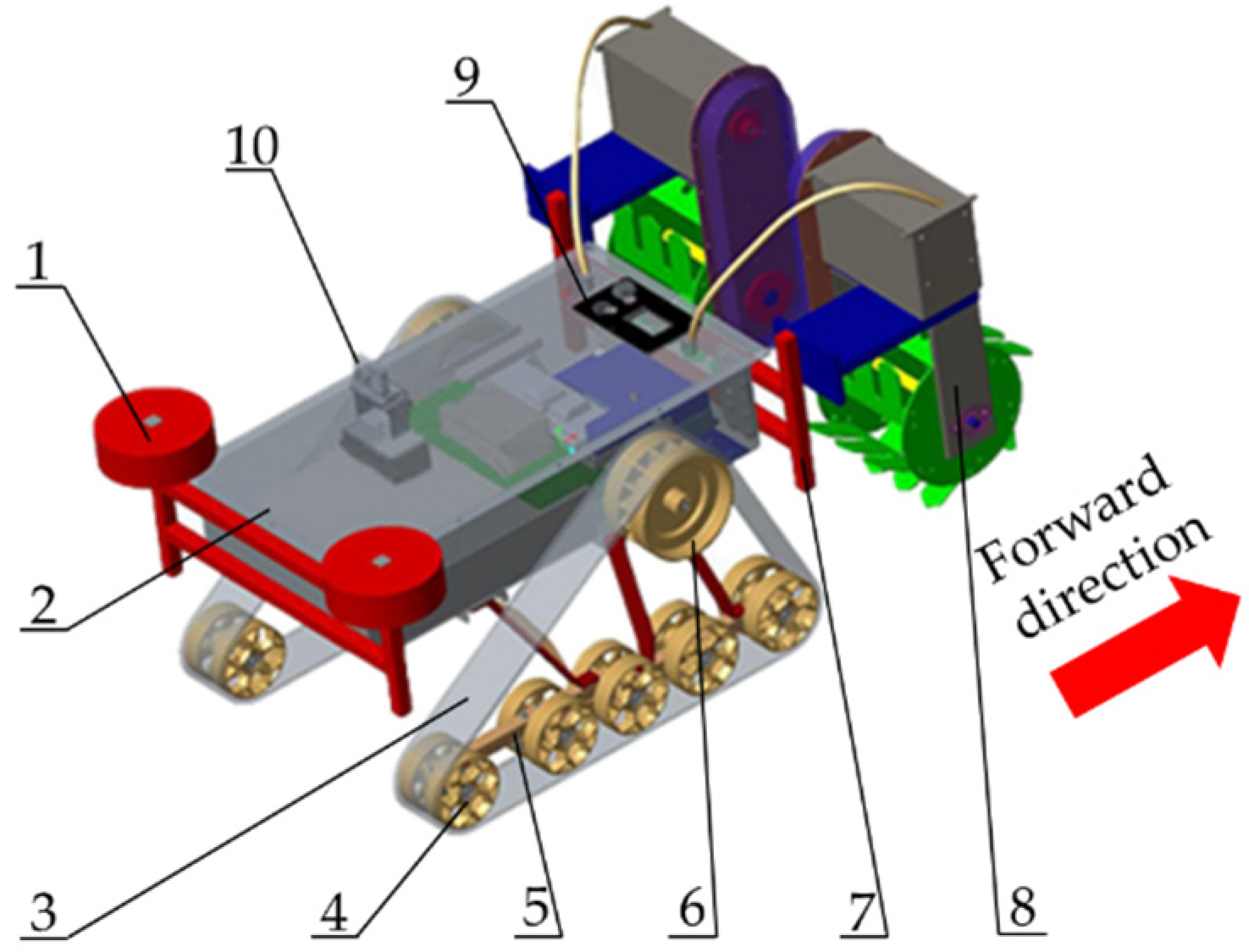
The inter row weeding device is mounted on a self-propelled power platform to form a paddy field self-propelled inter row weeder. The structure of the weeder is a connecting rod, a frame, crawlers, supporting wheels, suspension frames, driving wheels, an inter row weeding device, electric control equipment and a visual recognition system. The driving wheels, supporting wheels and crawlers constitute the walking system, which effectively increases the contact area with the field soil to prevent subsidence and realizes flexible steering based on the difference in the speeds of the driving wheels. The visual recognition system can effectively monitor the position of the seedling belt and ensure that the straight line runs between the lines. The inter row weeding device is mounted on the rear connecting rod of the machine, which allows the weeding spacing and height to be adjusted according to the agronomic requirements of rice planting in different regions, and it has good adaptability. The structure of the weeder is shown in Figure 1, and the technical parameters are shown in Table 1.
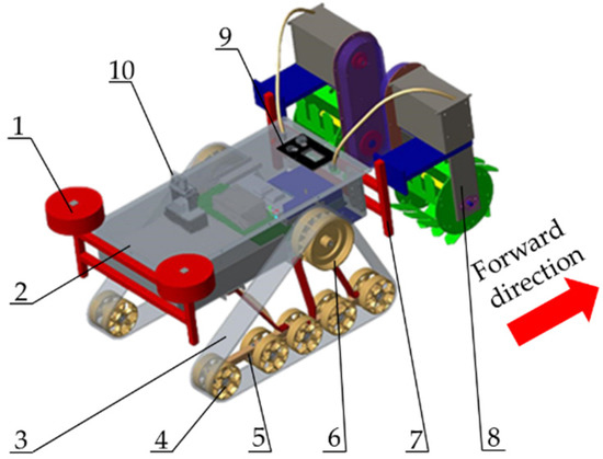
Figure 1.
Paddy field self-propelled inter row weeder: (1) connecting rod, (2) frame, (3) crawler, (4) supporting wheel, (5) Suspension Frame, (6) driving wheel, (7) rear connecting frame, (8) inter row weeding device, (9) electric control equipment, (10) visual recognition system.

Table 1.
Main technical parameters of a paddy field self-propelled inter row weeder.
When the machine is working, the visual recognition system extracts the surrounding environment information in real time and identifies the rice seedling belt through distortion correction, feature extraction, image noise reduction, and seedling belt fitting. After the image information is processed by the host computer, the deviation signal is transmitted to the electronic control equipment. The driving wheels transmitted through the planetary gear reducer decelerate to increase torque. When the driving force of the crawler is greater than the resistance of the weeder, the supporting wheels rotate in the crawler to complete the vision recognition of the seedling belt and inter row walking. The weeds are buried in the soil by disturbing and compacting the soil by driving the weeding wheels with rake teeth. The operational status is shown in Figure 2.
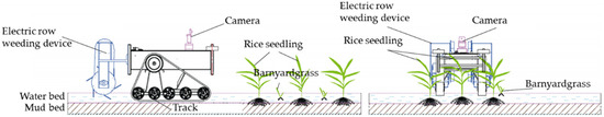
Figure 2.
Working status of the paddy field self-propelled inter row weeder.
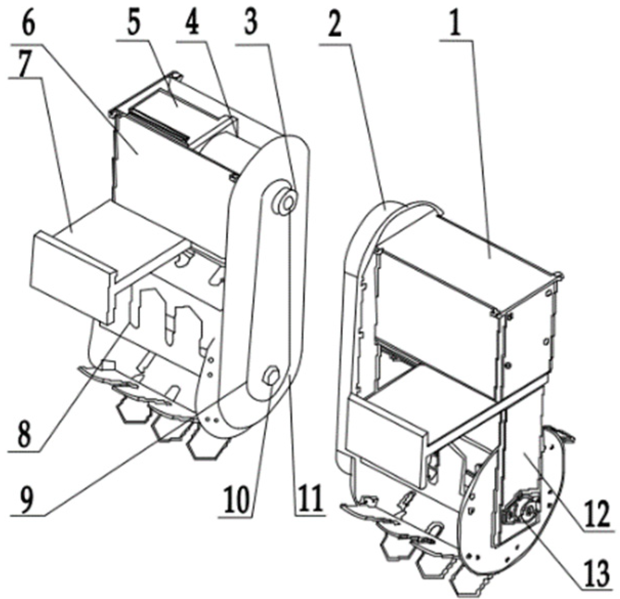
The inter row weeding devices are mainly composed of motor box covers, side transmission boxes, upper sprockets, planetary gear reducers, brushless DC motors, motor boxes, connecting plates, weeding wheels, lower sprockets, weeding wheel axles, chains, a bearing pedestal and weeding wheel frames. The overall structure is shown in Figure 3. The power of the device is provided by the motor, which is fixed on the chassis frame by bolts. By adjusting the position of the connecting plates on the left, right, top and bottom of the chassis, the row spacing and depth of weeding can be changed to meet and adapt to the operational requirements for different row spacing sizes and land conditions. Lateral transmission is realized by the upper sprocket, lower sprocket and chain.
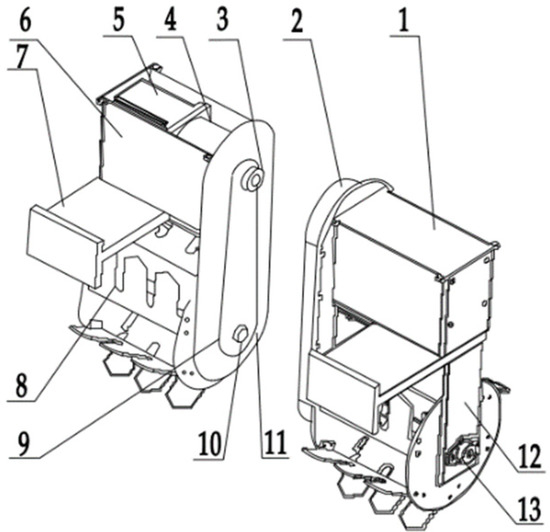
Figure 3.
Inter row weeding device: (1) motor box cover, (2) side transmission box, (3) upper sprocket, (4) planetary gear reducer, (5) brushless DC motor, (6) motor box, (7) connecting plate, (8) weeding wheel, (9) lower sprocket, (10) weeding wheel axle, (11) chain, (12) bearing pedestal, (13) weeding wheel frame.
2.2. Analysis of the Mechanism of Weeding by Burying
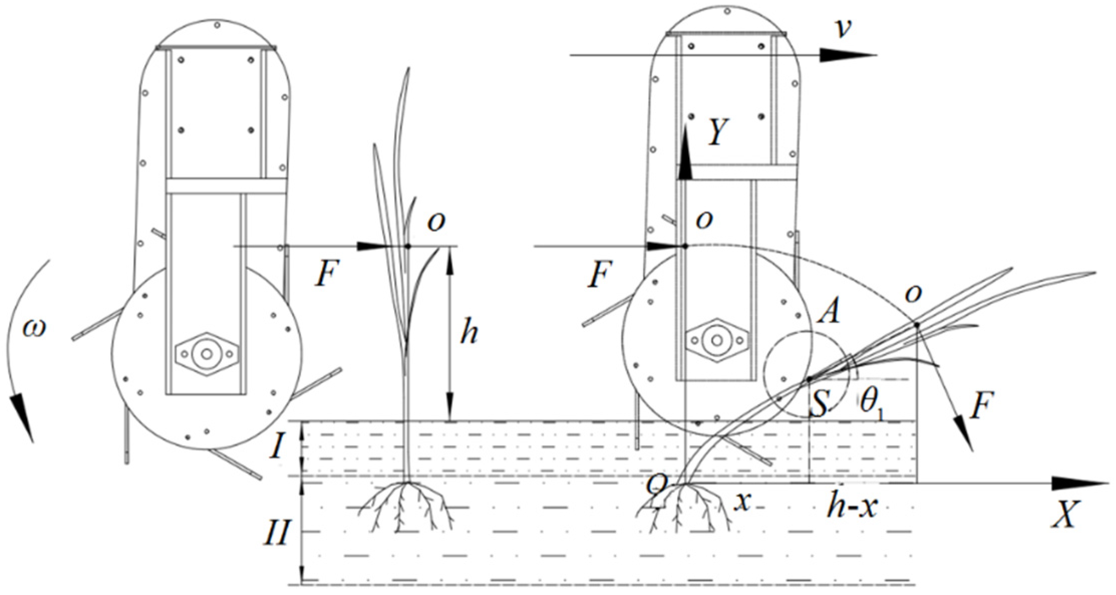
To study the mechanism of pressure burying weeding in paddy field, the dynamic analysis of pressure burying weeding is carried out by establishing the deflection curve equation of weeds, as shown in Figure 4. According to the simplified model of the actual weeding and burying process, the weed is simplified as a homogeneous cantilever beam with fixed lower end and free upper end [17]. Taking the miscellaneous grass root system as the coordinate origin O, the weed stem axis before bending deformation is the Y-axis, and the horizontal soil interface is the X-axis, a rectangular coordinate system XOY is established, in which the XOY plane is the longitudinal symmetry plane of the stem.

Figure 4.
Dynamic model of burying weeding: (I) water layer; (II) mud layer.
According to the principle of material mechanics, the axis of the bent weed stalk is simplified as a deflection curve, and the coordinates of any point on the curve are (x, y). Then, the deflection curve equation is as follows:
According to the plane assumption, the bending deformation of weeds is perpendicular to the axial cross section. Therefore, the included angle of the cross section is the angle between the Y axis and the normal direction of the deflection curve as follows:
In the case of pure bending, the relationship between the bending moment and curvature is as follows:
where ρ is the radius of curvature, m; M is the bending moment of the cross section of the weed stem, N·m; E is the elastic modulus of the weed stem, Pa; and I is the inertia moment of the cross section of the weed stem, m4.
Equation (2) can be converted to Equation (4).
where ds is the focus of both ends of the normal (the center of curvature), and the radius of curvature is determined as ρ.
Equation (6) is obtained by combining Equations (3)–(5).
Equation (6) is the equation of the nonlinear deflection curve of the deformed weed stem. To simplify the solution process, Equation (6) is linearized. When the weed stem is embedded in the soil layer, the bending angle θ1 is small and can be approximated as:
When the weeds are buried into the soil, the deflection curve is relatively flat, and is small. Equation (6) is converted to Equation (8) as follows:
where Equation (8) is the approximate differential equation of the deflection curve of the weed stem after being pressed into the soil.
On this basis, the dynamics of weeding wheels are analyzed, and the main factors affecting the burying effect are analyzed. When the weeding wheels collide with the weeds in the form of point contact (Action Point O), the weeds are buried in the soil. A certain moment is generated on any cross-section P of the weed rhizome.
where F is the concentrated force on the weed stem, N; g is the gravitational acceleration, m/s2; and h is the height of the force point, m.
Equation (10) is rearranged based on the combination of Equations (8) and (9).
Equation (11) is obtained by performing a quadratic integration of Equation (10).
where C and D are integral constants. When the action point is the coordinate origin (x = y = 0), the constant term (C = D = 0) is obtained.
In conclusion, the equation of the deflection curve of a weed stem buried in soil is as follows:
From the analysis of Equation (12), the elastic modulus E and section moment of inertia I are basically constant for a certain weed type. The common weeds in paddy field are barnyardgrass, arrowhead and sargassum, of which barnyardgrass is the most abundant and harmful [18]. In addition, the value of Elastic Modulus E and section moment of Inertia I of barnyardgrass are the largest in weeds, so the physical characteristics of barnyardgrass are mainly considered. When barnyardgrass was removed by burying, other weeds also be removed. When the depth of the weeding wheels in the soil is fixed, the height of the stress point h is constant, and the bending angle of the weeds decreases with increasing force F. Therefore, the greater the force is, the better the weeding effect is. When the force F of the structure on a weed remains unchanged, the bending angle of the weed increases with increasing height h of the stress point. Consequently, the higher the height of the stress point is, the less effective the weeding is.
2.3. Design of Driving Weeding Device with Rake Teeth
The weeding operation is only completed by the driving weeding device with rake teeth. Its structural composition: The driving weeding device with rake teeth was formed by the weeding wheels with rake teeth and the driving motor. The driving weeding device with rake teeth is carried on the self-propelled power platform to form a paddy field self-propelled inter row weeder.
2.3.1. Structural Design of Weeding Wheels with Rake Teeth
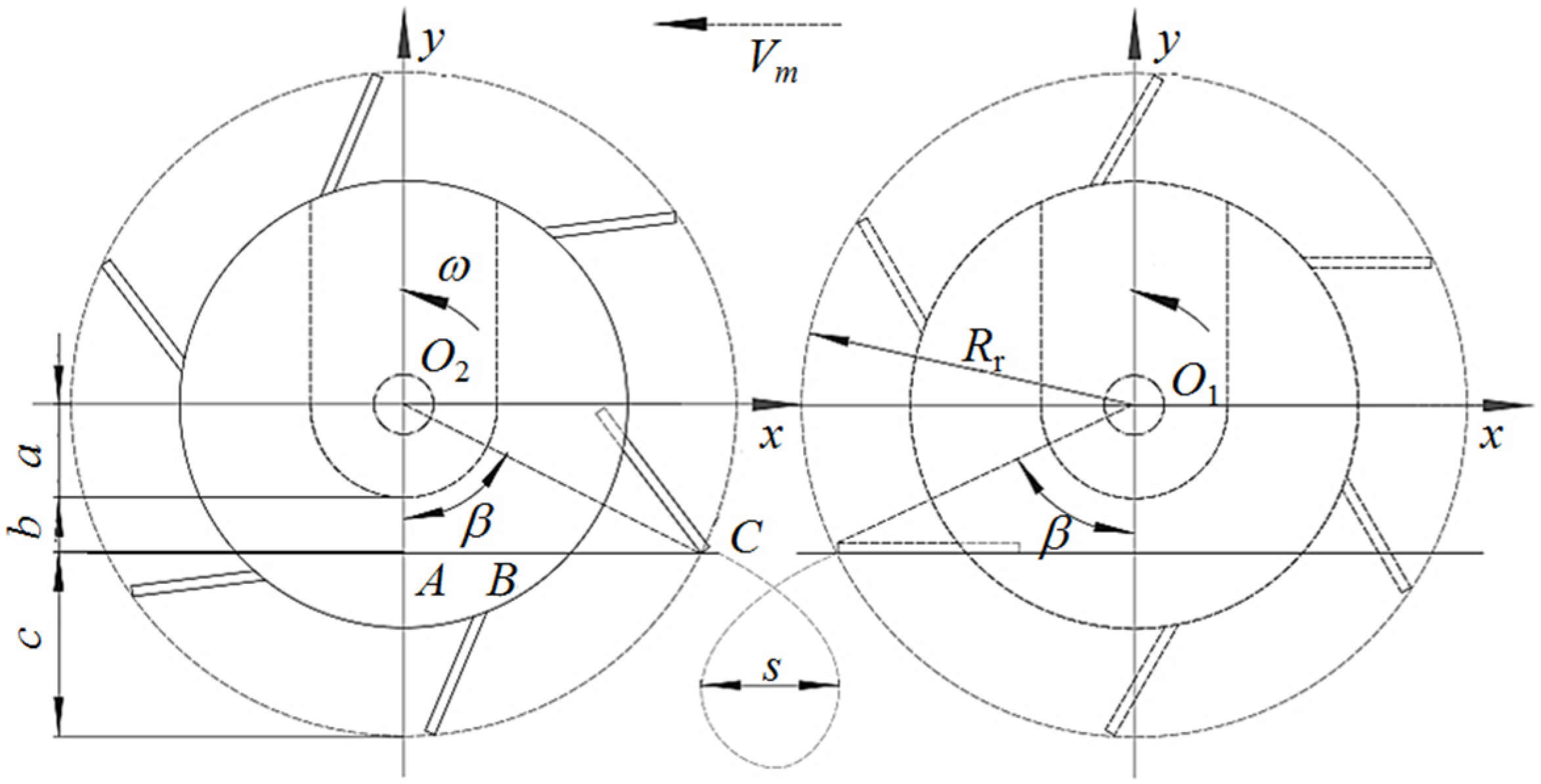
The designed weeding wheels with rake teeth could bury the weeds in the soil through rake teeth penetration and excavation, which disturbs and compacts the soil to achieve weeding and soil plowing. The diagram of the structure of the weeding wheels is shown in Figure 5.

Figure 5.
Diagram of the structure of a weeding wheel with rake teeth when working.
The turning radius of the weeding wheels Rr is:
where a is the distance from the center of the weeding wheel to the bottom of the transmission box, m, which is taken as 0.06 m; b is the distance between the bottom of the transmission box and the mud surface, m, which is taken as 0.002 m; and c is the weeding depth, m, according to the root length of the weeds, which is taken as 0.07 m.
In triangle OCA:
The rake teeth and the weeding disc are connected by bolts. To facilitate the installation, AB is taken as 0.1 m, and the installation position of the rake teeth can be determined by substituting the relevant parameters into Equations (14)–(16).
When the weeder is working, the path of the weeding rake teeth is a cycloid, and the weeding operation can be performed such that Equation (17) should be satisfied.
where Vm is the forward speed of
the weeder, m/s, which is taken as 1 m/s; ω is the angle speed of the
weeding wheels, rad/s, where
and n is the rotating speed of the weeding wheels, r/min. The calculated
rotational speed of the weeding wheels should be greater than 63 r/min and is
determined to be 70–150 r/min.
To ensure that leakage does not occur during working conditions, the sum of the action length of all the rake teeth on the weeding wheels should be greater than the forward distance when the weeding wheels rotate for one circle.
where Z is the number of all rake teeth on the weeding wheels and x is the action distance of a single rake tooth when the weeding wheels rotate for one cycle, m.
Equation (19) is obtained according to the geometric relationship of Figure 5.
where l1 is the forward distance of the weeder, m; β is the angle between the line from the tip of the rake tooth to the rotation center of the weeding wheels and the plumb line, (°); and Equations (17)–(21) give Z ≥ 5.36, where Z is rounded to 6, and the tooth width is 170 mm.
2.3.2. Power Analysis of the Driving Weeding Device with Rake Teeth
The driving weeding wheels with rake teeth adopt the driving rotary burying plowing mode during operation, and the matching driving motor forms the driving rake teeth weeding device, which can effectively ensure the working quality. In the selection of a driving motor, the working torque of the weeding device should be considered to prevent excessive power consumption.
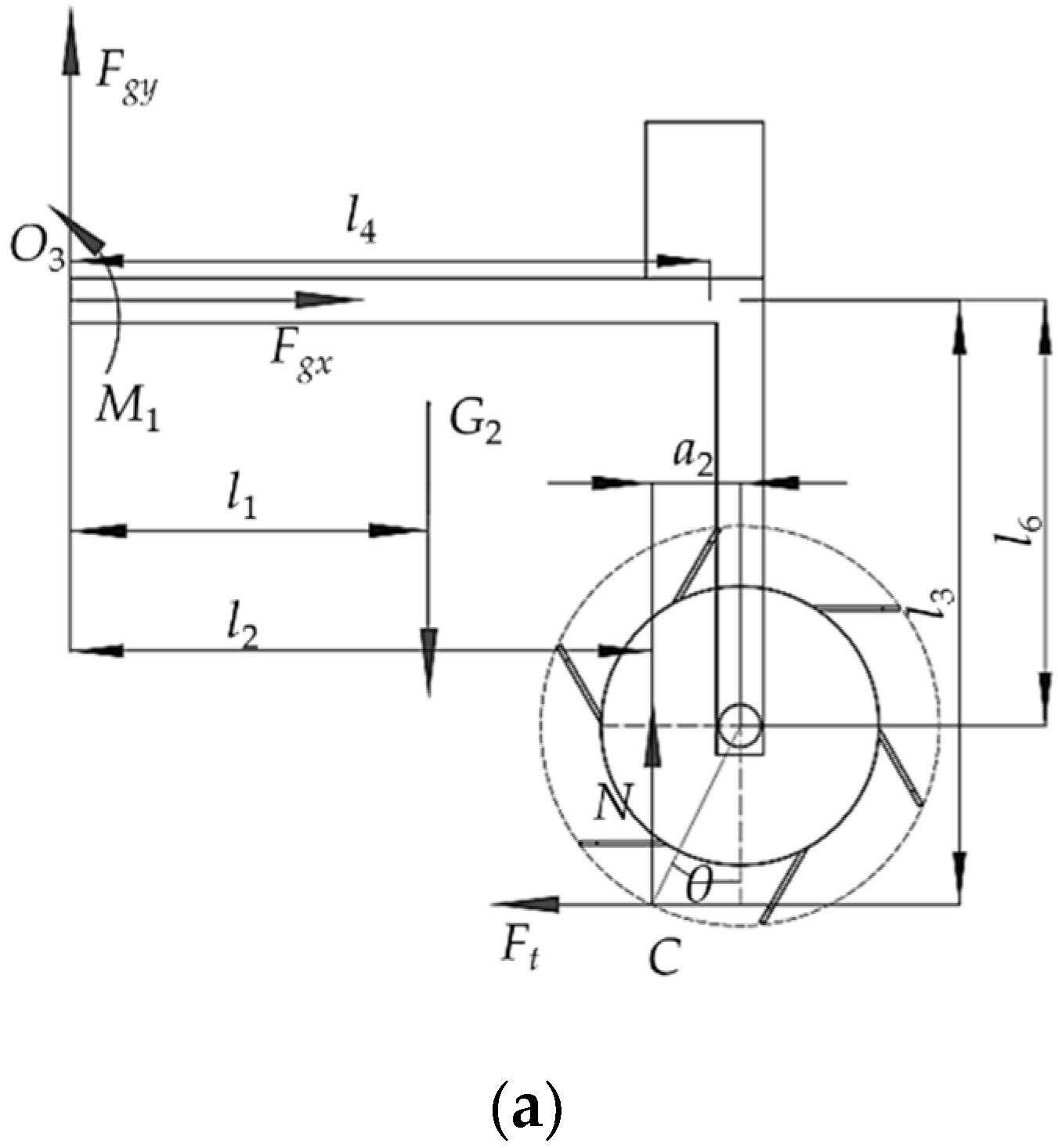
When the weeding device moves at a uniform speed, the force state of the weeding device is shown in Figure 6a, and the force balance equation is as follows:
where Fgy is the vertical force acting on the fixed end of the connecting plate, N; Fgx is the horizontal force on the fixed end of the connecting plate, N; M1 is the moment action on the fixed end of the connecting plate, N·m; G2 is the weight of a single weeding device, N, which is taken as 150 N; l1 is the horizontal distance from the center of gravity of the weeding device to the end face of the connecting plate, m, which is taken as 0.17 m; l2 is the horizontal distance from the point where the soil acts on the weeding wheel to the end face of the connecting plate, m; and l3 is the vertical distance from the point where the soil acts on the weeding wheel to the connecting plate, m; N is the soil support to the weeding wheel, N.
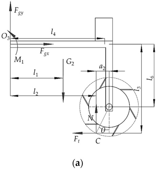
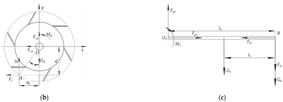
Figure 6.
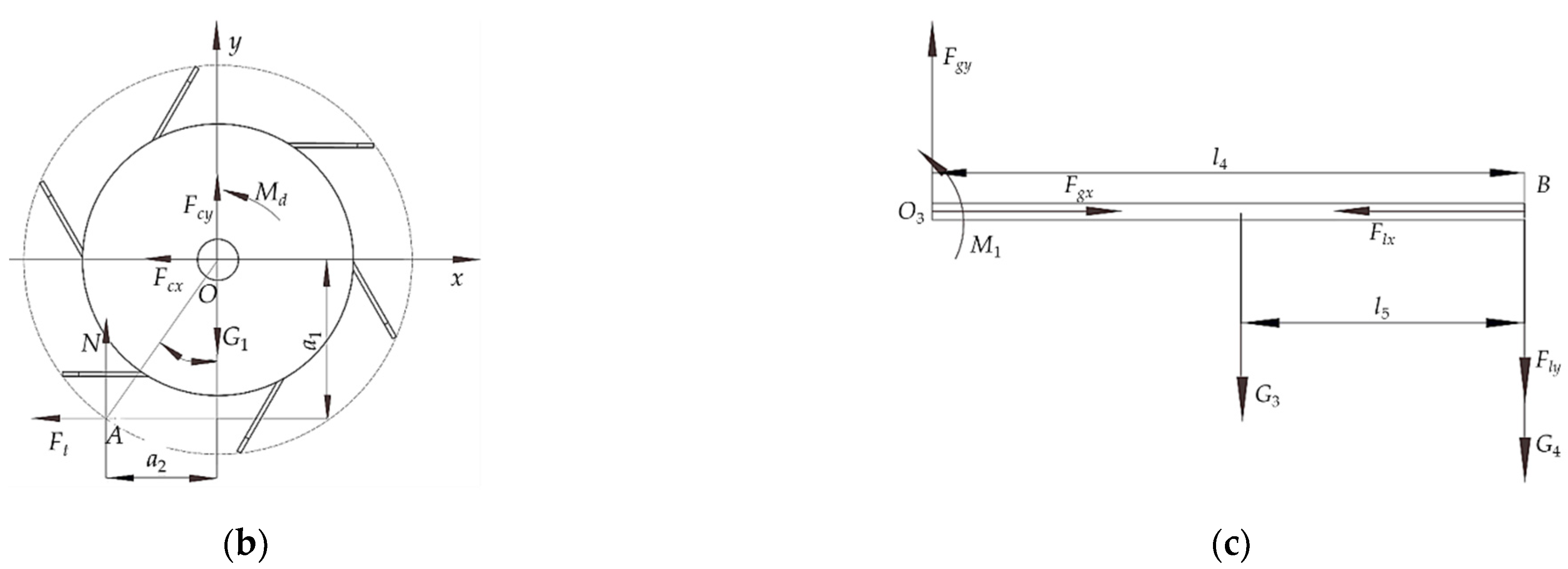
Force diagram of the weeding device: (a) overall stress diagram of the weeding device; (b) force diagram of the weeding wheel; (c) stress diagram of the connecting plate.
The stress state of a weeding wheel is shown in Figure 6b, and the balance equation is as follows:
where is the soil friction force on the weeding wheel, N; is the plumb distance from the rotation center to the soil force point, m; is the horizontal distance from the rotation center to the soil force point, m; and is the driving torque, N·m.
The stress state of the connecting plate of the weeding device is shown in Figure 6c, and the balance equation of the force is as follows:
where G3 is the gravity of the connecting plate, N, where G3 = 15 N; l4 is the horizontal distance from the pressure acting point of the motor and reducer on the connecting plate to the end face of the connecting plate, m, where l4 = 0.19 m; and l5 is the horizontal distance from the center of gravity of the connecting plate to the point where the pressure of the motor and reducer act on the connecting plate, m, where l5 = 0.11 m.
where fs is the rolling friction coefficient of the weeding wheel in soil.
Equation (28) is obtained by simultaneously solving Equations (24)–(27).
Equation (29) is obtained based on the substitution of relevant parameters.
where the range of θ and fs is 0– and 0–1, respectively, and the maximum value of Md is 10.34 N·m. The rotating speed of the weeding wheel is 70–150 r/min.
According to Equation (30), the motor power of the weeding device is 162.4 W. At present, most paddy field weeders are powered by small gasoline engines, which have the problems of violent vibration, loud noise and large weight. The motor has the advantages of convenient control, large starting torque, low noise and no pollution. Therefore, a 0.2 kW DC motor with a rotating speed of 3000 r/min and a reducer with a reduction ratio of 1:20 were selected.
According to the rated power of the optional motor, the capacity of the required battery can be calculated by Equation (31).
where Cv is battery capacity, AH; Pv is motor power, W; Tv is available time, h, where Tv ≥ 6 h; U is voltage, V, where U = 48 V.
The minimum battery capacity required for a driving weeding device with rake teeth is 25 AH.
2.4. Field Experiment
To test the working performance of the self-propelled inter row weeding device in a paddy field, weeding was performed on the self-propelled power platform for a field experiment in the experimental field of rice at Northeast Agricultural University on May 12, 2020, as shown in Figure 7. The experiment was carried out 14 days after transplanting. The rice variety was Longyang 16. The average height of the rice seedlings was 162 mm. No weeding was performed after transplanting. The weeds in the paddy field were mainly barnyardgrass. The average height of the barnyardgrass was 108 mm. The depth of the water layer and the depth of the mud layer were 35 mm and 155 mm, respectively. The average density of the inter row weeds was 52 plants/m2. The workers were skilled, and the machine was in good condition.
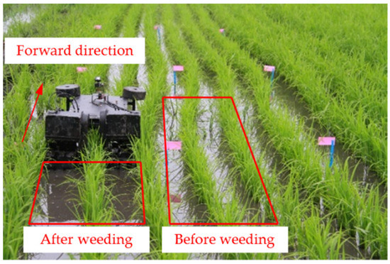
Figure 7.
Field experiment.
Several plots that were 10 m long and 0.6 m wide were selected as the test area, and an area of 1.5 m was selected as the acceleration area and buffer area of the machine before and after each test [19]. The machine was able to pass through the test area at a stable and uniform speed.
According to the burying weeding mechanism, the weeding force of the rake teeth is the most important factor that alters the effectiveness of weeding. If the weeding force is too large, the working efficiency of the machine is reduced and the seedling damage rate is too high, where the weeding force is related to the forward speed of the machine, the rotating speed of the weeding wheels and the weeding depth.
The forward speed of the machine, the rotational speed of the weeding wheels and the weeding depth (the weeding depth can be adjusted by controlling the mounting height of the inter row weeding device) were selected as the experimental factors and the inter row weeding rate was selected as the experimental index for a quadratic orthogonal rotation combination experiment with three factors and five levels. As the machine was mainly used for inter row weeding of rice seedlings in paddy fields, the inter row weeding rate was selected as the experimental index. The inter row weeding rate can be calculated by Equation (32) [20].
where Y is the inter row weeding rate, %; X1 is the total number of inter row weeds before weeding in the test area, plants; X2 is the total number of inter row weeds after weeding in the test area, plants.
The forward speeds of the machine were set to 0.43, 0.5, 0.6, 0.7 and 0.77 m/s, the rotating speeds of the weeding wheels were set to 86.4, 100, 120, 140 and 153 r/min, and the weeding depths were set to 43.2, 50, 60, 70 and 76.8 mm. The coding table of the experimental factor levels is shown in Table 2.
Table 2.
Coding table of the experiment factor level.
3. Results and discussion
3.1. Analysis of the Experiment Results in the Field
Three-factor and five-level quadratic orthogonal rotation combination experiments were performed, each experiment was repeated three times, and the average value of the experimental results was taken. The experimental scheme and analysis of the results were carried out by Design Expert 8.0 software, as shown in Table 3. The ANOVA table is shown in Table 4.
Table 3.
Experiment scheme and results.
Table 4.
Analysis of variance table.
According to the results of the variance analysis in Table 4, the F-value of the regression equation was 2.04, and the p-value was 0.1774, which means that the difference in lack of fit was not significant, and the fitting degree of the equation was good. The regression equations of the inter row weeding rate and forward speed, rotating speed of the weeding wheels and depth of weeding were established as follows:
The larger the F value is, the greater the influence of the experimental factors on the experimental indexes is [21]. Based on the F value of each factor, the order of the influence of the three factors on the weeding rate is as follows: the rotating speed of the weeding wheels > forward speed > weeding depth.
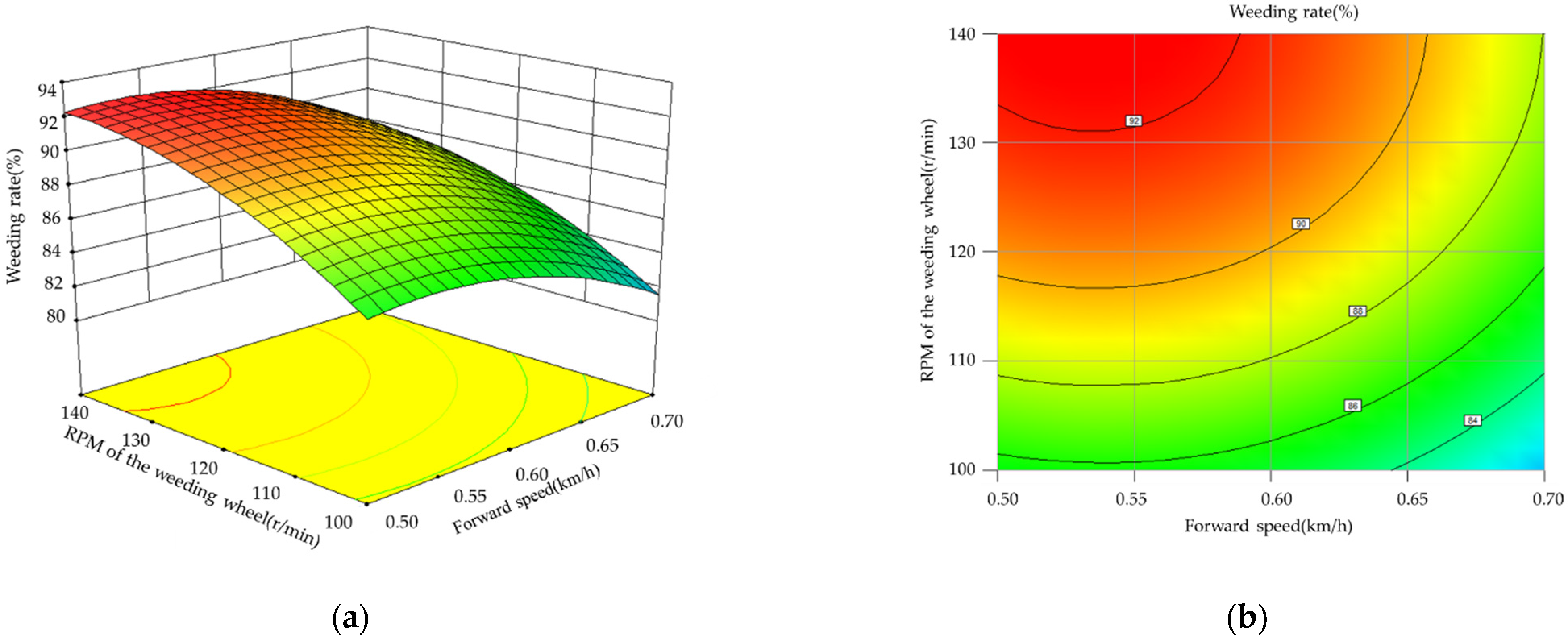
Design Expert 8.0 software was used to analyze the interaction of the forward speed, rotating speed of the weeding wheels and weeding depth. The response surface and contour map are shown in Figure 8, Figure 9 and Figure 10. The response surface and contour map of the influence of the forward speed and rotating speed of the weeding wheels on the inter row weeding rate are shown in Figure 8. When the forward speed was constant, the inter row weeding rate increased with increasing rotating speed of the weeding wheels. When the speed of the rotating weeding wheels was constant, the inter row weeding rate first increased and then slowly decreased with increasing forward speed. The response surface changed quickly along the direction of the rotating speed of the weeding wheels and relatively slowly along the direction of the forward speed, which indicated that the influence of the rotating speed of the weeding wheels on the inter row weeding rate was more significant than that of the forward speed on the inter row weeding rate.

Figure 8.
Influence of the forward speed and rotating speed of the weeding wheels on inter row weeding rate: (a) response surface; (b) contour map.

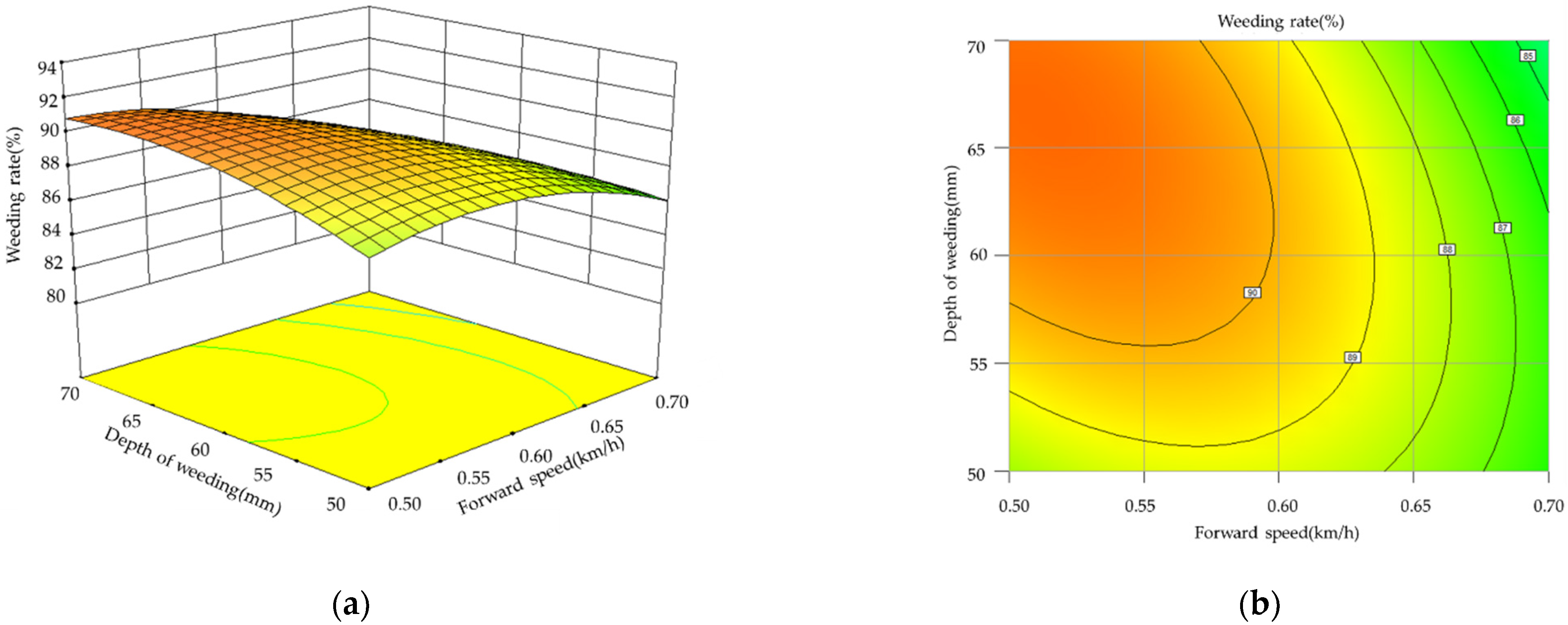
Figure 9.
Influence of the forward speed and weeding depth on the inter row weeding rate: (a) response surface; (b) contour map.

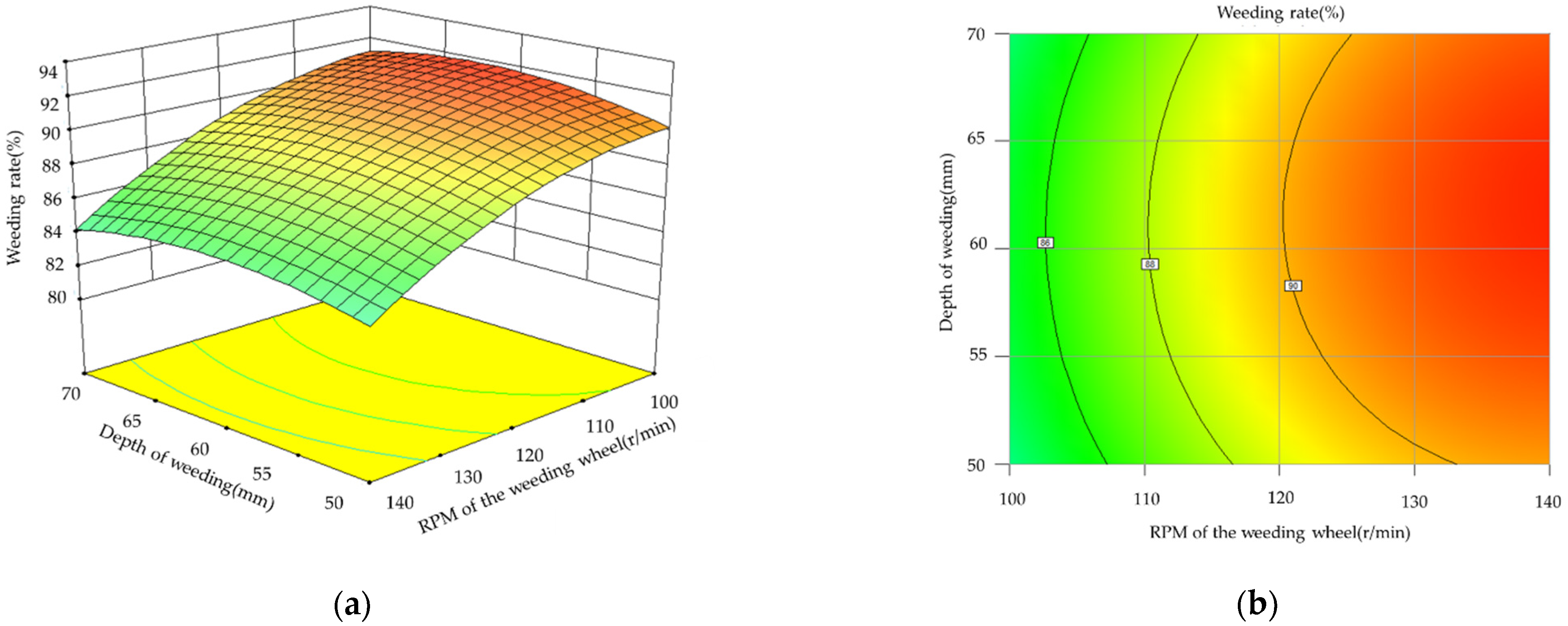
Figure 10.
Influence of the rotating speed of the weeding wheels and weeding depth on the inter row weeding rate: (a) response surface; (b) contour map.
The response surface and contour map of the influence of the forward speed and depth on the inter row weeding rate are shown in Figure 9. When the forward speed was constant, the inter row weeding rate increased slowly with increasing weeding depth. When the weeding depth was constant, the inter row weeding rate increased first and then decreased slowly with increasing forward speed. The response surface changed quickly along the direction of the forward speed and relatively slowly along the direction of the weeding depth, which indicated that the influence of the forward speed on the inter row weeding rate was more significant than that of the weeding depth on the inter row weeding rate.
The response surface and contour map of the influence of the rotating speed weeding wheels and weeding depth on the inter row weeding rate are shown in Figure 10. When the rotating speed of the weeding wheels was constant, the inter row weeding rate first slowly increased and then slowly decreased with increasing weeding depth. When the weeding depth was constant, the inter row weeding rate increased with the increase in the rotating speed of the weeding wheels. The response surface changed quickly along the direction of the rotating speed of the weeding wheels and relatively slowly along the direction of the weeding depth, which indicated that the influence of the rotation speed of the weeding wheels on the inter row weeding rate was more significant than that of the weeding depth on the inter row weeding rate.
To improve the inter row weeding rate, the best parameter combinations for the forward speed, rotating speed of the weeding wheels and weeding depth were explored, and the experimental factors were optimized. The experimental factors and performance indexes should meet certain conditions. First, the inter row weeding rate should be maximized to meet the weeding requirements. Then, to ensure efficient weeding, the forward speed and rotating speed of the weeding wheels should be maximized. In addition, the weeding depth did not have a significant effect on the inter row weeding rate, and the rotating conditions could be taken as the mean value. The parameterized mathematical model was established as follows:
The multi-objective parameter optimization module of Design Expert 8.0 data analysis software was used to optimize the mathematical model, and the optimal combination of parameters was obtained as follows: the forward speed was 0.64 m/s, the rotating speed of the weeding wheels was 140 r/min, the weeding depth was 56.8 mm, and the inter row weeding rate of the model was predicted to be 88.43%. To verify the accuracy of the optimal design model, the forward speed was 0.64 m/s, the rotating speed of the weeding wheels was 140 r/min, the weeding depth was 56.8 mm, and the inter row weeding rate was set as the verification index. The validation experiment was repeated five times, and the average value was taken. The quantic inter row weeding rates obtained from the field verification experiments were 86.23%, 85.41%, 89.60%, 87.19% and 86.85%. The average inter row weeding rate of the quantic experiments was 87.06%. The experimental results were basically consistent with the optimization results, the relative error was 1.5%, and the error was within an acceptable range. The complex paddy field environment, the forward vibration of the machine, the straightness of the driving path and other factors that can cause a change in the weeding effect may account for the relative error. However, with the increase in repeated experiments, the actual experimental results will be closer to the model prediction results. The inter row weeding rate generally met the agronomic requirements.
This paper mainly studies the mechanical inter row weeding parts, compared with chemical spraying weeding, mechanical weeding has become a key measure for the production of organic rice because of its advantages of not polluting the environment, increasing soil aeration, and improving the soil temperature. Therefore, the weeding effects of the driving weeding device with rake teeth developed in this study and the mechanical inter row weeding parts (including bending elastic tooth weeding wheel, swing weeding roller, spiral cutter tooth weeding wheel, compound weeding wheel and rotary swing weeding roller) widely used at present were compared and analyzed, as shown in Table 5. Compared with the common row weeding device, the driving weeding device with rake teeth has better weeding effect.
Table 5.
Comparison of weeding effect of mechanical inter row weeding parts.
3.2. Discussion
The burying weeding working mode was proposed, the weeding device with driving rake teeth was designed, and the structural parameters and working parameters were optimized to improve the comprehensive operation performance. In the actual operation process in the field, not only is the weeding device needed to effectively ensure the quality of weeding but its effect on paddy soil tillage also needs to be improved to increase the porosity of soil and effectively promote nutrient absorption in the field management period. Due to the complex working environment of paddy fields, the interaction mechanism between mechanical components, water and soil is very complex and cannot be completely determined through theoretical analysis. With the development of computer technology, virtual simulation provides a good technical method for this aspect of study. Many scholars have performed relevant simulation research on this topic. Bentaher et al. [22] simulated the interaction between plows and soil through the finite element method and explored the best plow angle. Zhang et al. [23] established a soil model by using discrete element simulation software and explored the best parameter combination of the trencher of a direct seeding machine for rape. Kotroczet al. [24] used the discrete element method to simulate the infiltration of soil through the cone permeameter and effectively evaluated the mechanical properties of the soil. Most of the above studies focus on dry land with single soil characteristics and obvious particle properties, which is not suitable for complex paddy field environments. The weeding wheel blends the water and soil [25,26]. However, the paddy field environment cannot be directly observed and analyzed through actual operation. Therefore, to simulate the soil plowing state of optimized weeding wheels, the explicit dynamics software LS-DYNA was used to establish the fluid–solid coupling model of weeding wheels and water soil. The weeding wheels were placed in a paddy field to analyze the soil disturbance and coupling stress.
The model of the weeding wheels was simplified to reduce the simulation time and to reasonably and effectively perform simulations and calculations [27,28]. All materials are defined as rigid bodies, and irrelevant parts are removed. The model of the weeding wheels was meshed by hexahedral grid cells, and the K-files were generated and imported into LS-Prepost of LS-DYNA. The material of the weeding wheels uses the MAT_RIGID keyword, and the parameters of the area were as follows: the density was 0.00786 g/mm3, the elastic modulus was 2.12 × 10⁵ MPa, and the Poisson’s ratio was 0.288 [29].
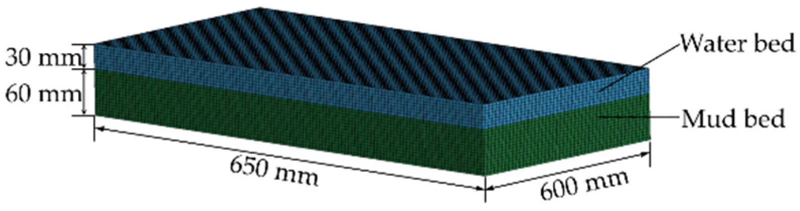
The water layer model and soil model were established by LS-Prepost of LS-DYNA. The water model is directly built on the soil model. The node coincidence command is used to overlap the nodes of the two cuboid models to form the coupling model of water and soil. According to the agronomic requirements, the size of the model of the water layer was set at 650 × 300 × 30 mm, and the size of the soil model was set at 650 × 300 × 60 mm. MAT_NULL in LS-DYNA was selected as the water layer material. The density was 0.001 g/mm3, and the cutoff pressure was −1 × 10⁻⁵ MPa [30]. The EOS equation of state was defined to determine the material parameters of soil and air. MAT_FHWA_SOIL in LS-DYNA was selected as the soil layer material. The main parameters were as follows: the soil density was 0.00161 g/mm3, soil particle density was 0.00273 g/mm3, bulk modulus was 5.6 MPa, shear modulus was 1.9 MPa, cohesion was 0.0155 MPa, internal friction angle was 15°, and water content was 40% [31]. The selection of other parameters was based on the previously determined value of MAT147.
The solid grid cell of the multi-material ALE algorithm was used to define the type of water grid and soil grid cell. To realize the mutual mixing of water and soil in the model, the multi-material coupling ALE_MULTI_MATERIAL_GROUP keyword was used in the model. After setting the keyword command, a cell was allowed to contain multiple ALE materials. To simulate the real environment of water and soil, the gravity condition was applied to the water–soil coupling model. The BOUNDARY_NON_REFLECTING keyword was used to constrain the surface of the soil and water, and the full constraint of SPC was applied to the bottom of the soil. ALE mesh smoothing was activated by the CONTROL_ALE keyword. The water-soil composite model is shown in Figure 11.

Figure 11.
Water soil composite model.
Based on the working state of the optimized weeding wheel and the agronomic requirements for weeding, the forward speed was 0.64 m/s, the rotating speed of the weeding wheels was 140 r/min, and the weeding depth was 56.8 mm. The coupling keyword command of the fluid structure was CONSTRAINED_LAGRANGE_IN_SOLID. The ALE element (water-soil model) was defined as MASTER, the Lagrange element (weeding wheels model) was defined as SLAVE, and the penalty coupling algorithm was set to simulate fluid–solid coupling. The simulation process is shown in Figure 12.
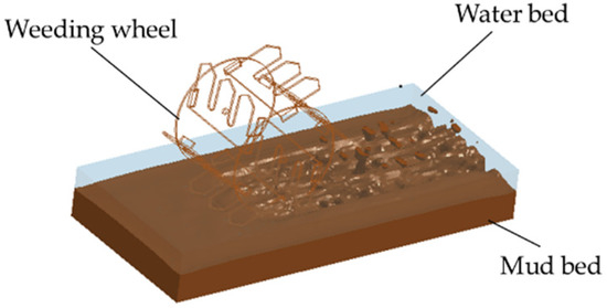
Figure 12.
Fluid–solid coupling simulation of the weeding wheels and water soil.
LS-Prepost can be used to analyze the density distribution at different times, and the density distribution is shown in Figure 13.
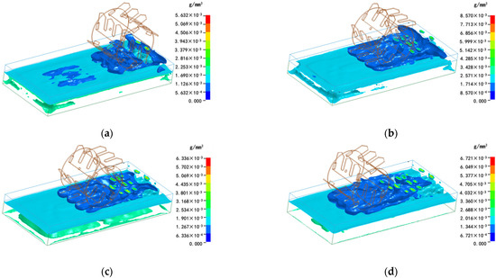
Figure 13.
Density distribution map: (a–d) represent density distribution map at different times.
Figure 13 shows that the pressure generated by the contact between the weeding rake teeth and the topsoil destroys the topsoil, and the weeding wheels greatly disturb the mud layer after entering the soil. As the simulation time increases, the weeding wheels continue to roll in the soil model. The path density increases significantly after the disturbance of the weeding wheel, which is due to the effect of the weeding wheel plowing the soil layer under the water layer. The results show that the weeding wheels greatly disturbed the soil and could bury weeds and plow soil.
The coupling stress is the average value of the coupling stress generated on the coupling surface during the interaction between the weeding components and the water–soil model. The smaller the coupling stress is, the smaller the resistance of the component and the smaller the operation energy consumption [32]. The stress distribution at different times was measured by LS-Prepost. The stress distribution is shown in Figure 14.
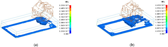
Figure 14.
Stress distribution diagram: (a–d) represent stress distribution diagram at different times.
Figure 14 shows that after the rake teeth of the weeding wheels were embedded in the soil, the back of the rake teeth compressed the soil in the direction of rotation while the weeding wheels rotated, so the stress on the soil on the backside of the weeding wheels with rake teeth was positive. The soil on the front of the rake teeth was subject to negative tensile stress as the rake teeth plowed backward and disturbed the soil. As the rake teeth were distributed in a uniform distribution and circumferential arrangement on the weeding wheels, the coupling stress of the weeding wheels and water–soil composite model was in a pulse state with the rake teeth entering the soil successively. In addition, when the weeding wheels moved in the simulated paddy field environment, the mud mixture did move, and the overall coupling stress was small, which indicated that the resistance of the weeding parts was small and the energy consumption of the weeding wheels was low. Based on the results of the field experiment, the design of the weeding wheels is reasonable.
In the field experiment, a large soil disturbance would lead to seedling damage when the weeding wheel was activated because the soil in the paddy field was soft. In the follow-up research stage, modern testing technology was used to design and build a real-time test system for the force of seedling damage. Combined with the actual operation situation, the damage index of rice seedlings was defined artificially, and the influence trend of various factors on the damage force of rice seedlings was analyzed to determine the critical force value that can not only control weeds but also mitigate damage to rice seedlings.
Barnyardgrass is the main weed type in paddy field, and the growth of this kind of grass mainly depends on the photosynthesis of leaves. When the paddy field weeding wheel disturbs the mud layer at the bottom of the paddy field, burying weeds and preventing photosynthesis can achieve the effect of weeding. According to the soil characteristics of paddy field, the method of buried weeding is only suitable for paddy field. The weeding wheel designed in this study can not only bury weeds, but also has good tillage effect through simulation test. At present, the paddy field weeder developed by researchers only focused on the weeding effect within one week after weeding [21,33]. In order to show the feasibility in the actual production process, a field management comparative test shall be carried out in the later stage. A comparative analysis between the non-use of weeders, the use of conventional weeders and the use of paddy field self-propelled inter row weeders shall be carried out. The growth of rice after weeding, and comprehensively verifying the weeding effect and tillage effect of weeders from the aspects of the weeding rate and rice harvest shall be tracked, so as to form a systematic system for the development and production management of weeding devices. This study provides a theoretical basis for the accuracy and efficiency of weeding and provides a reference for the intelligent development and reliable application of paddy field weeding equipment.
4. Conclusions
- (1)
- In view of the poor quality of weeding mechanics and the lack of an obvious effect of plowing in the complex environment of paddy fields, a new method of pressing and burying was proposed, and the main factors that alter the burying effectiveness were explored. The structure of weeding wheels with rake teeth was designed and matched with appropriate power, and the rake teeth weeding device was optimized.
- (2)
- The forward speed of the machine, rotating speed of the weeding wheels and depth of weeding were selected as the experimental factors, and the inter row weeding rate was selected as the experimental index. An orthogonal combination experiment of three factors and five levels of secondary rotation was designed and optimized. The results showed that when the forward speed was 0.64 m/s, the rotational speed of the weeding wheels was 140 r/min, and the weeding depth was 56.8 mm, the predicted index of the inter row weeding rate was 88.43%. The inter row weeding rate determined by confirmatory experiments was 87.06%, which met the requirements of weeding agronomy.
- (3)
- LS-DYNA was used to build the model of the fluid–solid coupling simulation of weeding wheels and water soil. The soil disturbance and stress distribution of the optimized weeding wheels were studied. The results showed that the effect of plowing of the weeding wheels was good.
The design of the device can improve the quality of inter row weeding working in paddy fields and the effect of soil plowing, which has a certain guiding significance for the design and development of weeding components in paddy fields and the simulation of paddy field machinery and soil coupling. This method will be used to perform the optimization design and coupling analysis of weeding components among plants in the future to promote the green and efficient development of weeding in paddy fields.
Author Contributions
Conceptualization, J.W. (Jinwu Wang), H.T. and C.X.; methodology, C.X. and Q.W.; software, Y.X.; validation, J.W. (Jinfeng Wang) and W.Z.; investigation, J.W. (Jinfeng Wang) and H.T.; resources, J.W. (Jinwu Wang) and H.T.; data curation, H.T. and Q.W.; writing—original draft preparation, C.X. and H.T.; writing—review and editing, J.W. (Jinwu Wang), W.Z. and H.T.; visualization, C.X.; supervision, J.W. (Jinwu Wang) and H.T.; funding acquisition, J.W. (Jinwu Wang) and H.T. All authors have read and agreed to the published version of the manuscript.
Funding
This work was funded by the National Natural Science Foundation of China, Grant Number: 51875098, and the Program on Industrial Technology System of National Rice (CN), Grant Number: CARS-01–48.
Institutional Review Board Statement
Not applicable.
Informed Consent Statement
Not applicable.
Data Availability Statement
All data are presented in this article in the form of figures and tables.
Conflicts of Interest
The authors declare no conflict of interest.
References
- Wang, X.; Jing, Z.H.; He, C.; Liu, Q.Y.; Qi, J.Y.; Zhao, X.; Xiao, X.P.; Zhang, H.L. Temporal variation of SOC storage and crop yield and its relationship—A fourteen year field trial about tillage practices in a double paddy cropping system, China. Sci. Total Environ. 2021, 759, 143494. [Google Scholar] [CrossRef]
- Zhou, L.; Liu, Z.; Zhou, T. Qualitative Analysis of the Effect of Weeds Removal in Paddy Ecosystems in Fallow Season. Discret. Dyn. Nat. Soc. 2020, 2020, 1–12. [Google Scholar] [CrossRef]
- Shimada, N.; Sugiura, S. Indirect effects of weeds on rice plants via shared heteropteran herbivores. J. Appl. Entomol. 2021, 145, 117–124. [Google Scholar] [CrossRef]
- Ma, X.; Qi, L.; Liang, B.; Tan, Z.; Zuo, Y. Present status and prospects of mechanical weeding equipment and technology in paddy field. Nongye Gongcheng Xuebao/Trans. Chin. Soc. Agric. Eng. 2011, 27, 162–168. [Google Scholar] [CrossRef]
- Tewari, V.K.; Ashok Kumar, A.; Nare, B.; Prakash, S.; Tyagi, A. Microcontroller based roller contact type herbicide applicator for weed control under row crops. Comput. Electron. Agric. 2014, 104, 40–45. [Google Scholar] [CrossRef]
- Qi, L.; Ma, X.; Tan, Z.; Tan, Y.; Qiu, Q.; Yang, C.; Zhang, W. Development and experiment of marching-type inter-cultivation weeder for paddy. Nongye Gongcheng Xuebao/Trans. Chin. Soc. Agric. Eng. 2012, 28, 31–35. [Google Scholar] [CrossRef]
- Krähmer, H.; Andreasen, C.; Economou-Antonaka, G.; Holec, J.; Kalivas, D.; Kolářová, M.; Novák, R.; Panozzo, S.; Pinke, G.; Salonen, J.; et al. Weed surveys and weed mapping in Europe: State of the art and future tasks. Crop. Prot. 2020, 129, 105010. [Google Scholar] [CrossRef]
- Houngbédji, T.; Dessaint, F.; Nicolardot, B.; Shykoff, J.A.; Gibot-Leclerc, S. Weed communities of rain-fed lowland rice vary with infestation by Rhamphicarpa fistulosa. Acta Oecologica 2016, 77, 85–90. [Google Scholar] [CrossRef]
- Machleb, J.; Peteinatos, G.G.; Kollenda, B.L.; Andújar, D.; Gerhards, R. Sensor-based mechanical weed control: Present state and prospects. Comput. Electron. Agric. 2020, 176, 105638. [Google Scholar] [CrossRef]
- Zhang, Q.; Shaojie Chen, M.E.; Li, B. A visual navigation algorithm for paddy field weeding robot based on image understanding. Comput. Electron. Agric. 2017, 143, 66–78. [Google Scholar] [CrossRef]
- Yamada, Y.; Iwakabe, K.; Liu, G.; Uejima, T. Mechanical weeding using a paddy field mobile robot for paddy quality improvement. In Proceedings of the Lecture Notes in Computer Science (Including Subseries Lecture Notes in Artificial Intelligence and Lecture Notes in Bioinformatics), Birmingham, UK, 1–3 September 2014; Volume 8069, pp. 185–189. [Google Scholar]
- Qin, C.; Du, Q.; Tian, L.; Huang, X. The control system design of automatic weeding robot based on visual navigation. In Proceedings of the 2012 IEEE International Conference on Robotics and Biomimetics, ROBIO 2012—Conference Digest, Guangzhou, China, 11 December 2012; pp. 956–961. [Google Scholar] [CrossRef]
- Wang, J.; Niu, C.; Zhang, C.; Wei, C.; Chen, Z. Design and experiment of 3ZS-150 paddy weeding-cultivating machine. Nongye Jixie Xuebao/Trans. Chin. Soc. Agric. Mach. 2011, 42, 75–79. [Google Scholar]
- Qi, L.; Zhao, L.; Ma, X.; Cui, H.; Zheng, W.; Lu, Y. Design and test of 3GY-1920 wide-swath type weeding-cultivating machine for paddy. Nongye Gongcheng Xuebao/Trans. Chin. Soc. Agric. Eng. 2017, 33, 47–55. [Google Scholar] [CrossRef]
- Tao, G.; Wang, J.; Zhou, W.; Niu, C.; Zhao, J. Herbicidal mechanism and key components design for paddy weeding device. Nongye Jixie Xuebao/Trans. Chin. Soc. Agric. Mach. 2015, 46, 57–63. [Google Scholar] [CrossRef]
- Wang, J.; Li, X.; Ma, X.; Zhou, W.; Tang, H. Small tracked and remote-controlled multifunctional platform for paddy field. Int. Agric. Eng. J. 2018, 27, 172–182. [Google Scholar]
- Xu, Q.; Tang, L.; Gu, D.; Jiang, H.; Cao, W.; Zhu, Y. Architectural parameter-based three dimensional modeling and visualization of rice roots. Nongye Gongcheng Xuebao/Trans. Chin. Soc. Agric. Eng. 2010, 26, 188–194. [Google Scholar] [CrossRef]
- Wang, J.; Wang, J.; Yan, D.; Tang, H.; Zhou, W. Design and Experiment of 3SCJ-2 Type Row Weeding Machine for Paddy Field. Nongye Jixie Xuebao/Trans. Chin. Soc. Agric. Mach. 2017, 48, 71–78. [Google Scholar] [CrossRef]
- Wang, J.; Li, C.; Li, X.; Li, X.; Wang, J. Design and Experiment of 3SCJ-1 Type Weeding Machine for Paddy Field Applied to Film Mulching and Transplanting. Nongye Jixie Xuebao/Trans. Chin. Soc. Agric. Mach. 2018, 49, 102–109. [Google Scholar] [CrossRef]
- Wang, J.; Gao, G.; Yan, D.; Wang, J.; Weng, W.; Chen, B. Design and Experiment of Electric Control Double Row Deep Fertilizing Weeder in Paddy Field. Nongye Jixie Xuebao/Trans. Chin. Soc. Agric. Mach. 2018, 49, 46–57. [Google Scholar] [CrossRef]
- Wu, C.; Zhang, M.; Jin, C.; Tu, A.; Lu, Y.; Xiao, T. Design and experiment of 2BYS-6 type paddy weeding-cultivating machine. Nongye Jixie Xuebao/Trans. Chin. Soc. Agric. Mach. 2009, 40, 51–54. [Google Scholar]
- Bentaher, H.; Ibrahmi, A.; Hamza, E.; Hbaieb, M.; Kantchev, G.; Maalej, A.; Arnold, W. Finite element simulation of moldboard-soil interaction. Soil Tillage Res. 2013, 134, 11–16. [Google Scholar] [CrossRef]
- Zhang, Q.; Liao, Q.; Ji, W.; Liu, H.; Zhou, Y.; Xiao, W. Surface optimization and experiment on ditch plow of direct rapeseed seeder. Nongye Jixie Xuebao/Trans. Chin. Soc. Agric. Mach. 2015, 46, 53–59. [Google Scholar] [CrossRef]
- Kotrocz, K.; Mouazen, A.M.; Kerényi, G. Numerical simulation of soil-cone penetrometer interaction using discrete element method. Comput. Electron. Agric. 2016, 125, 63–73. [Google Scholar] [CrossRef] [Green Version]
- Jiang, Q.; Cao, M.; Wang, Y.; Wang, J.; He, Z. Quantification of the soil stiffness constants using physical properties of paddy soils in Yangtze Delta Plain, China. Biosyst. Eng. 2020, 200, 89–100. [Google Scholar] [CrossRef]
- Xie, Y.; Hong, Y.; Zhang, X.; Ren, J. Analysis of mud splashing pattern of paddy field blade using computational fluid dynamics. Comput. Electron. Agric. 2020, 176, 105639. [Google Scholar] [CrossRef]
- Liu, F.; Yang, Y.; Zeng, Y.; Liu, Z. Bending diagnosis of rice seedling lines and guidance line extraction of automatic weeding equipment in paddy field. Mech. Syst. Signal. Process. 2020, 142, 106791. [Google Scholar] [CrossRef]
- Alba, O.S.; Syrovy, L.D.; Duddu, H.S.N.; Shirtliffe, S.J. Increased seeding rate and multiple methods of mechanical weed control reduce weed biomass in a poorly competitive organic crop. Field Crop. Res. 2020, 245, 107648. [Google Scholar] [CrossRef]
- Choi, K.H.; Han, S.K.; Han, S.H.; Park, K.H.; Kim, K.S.; Kim, S. Morphology-based guidance line extraction for an autonomous weeding robot in paddy fields. Comput. Electron. Agric. 2015, 113, 266–274. [Google Scholar] [CrossRef]
- Shinoto, Y.; Otani, R.; Matsunami, T.; Maruyama, S. Analysis of the shallow root system of maize grown by plowing upland fields converted from paddy fields: Effects of soil hardness and fertilization. Plant. Prod. Sci. 2020, 24, 297–305. [Google Scholar] [CrossRef]
- Gholizadeh, A.; Amin, M.S.M.; Borůvka, L.; Saberioon, M.M. Models for Estimating the Physical Properties of Paddy Soil Using Visible and Near Infrared Reflectance Spectroscopy. J. Appl. Spectrosc. 2014, 81, 534–540. [Google Scholar] [CrossRef]
- Qi, L.; Liang, Z.; Ma, X.; Tan, Y.; Jiang, L. Validation and analysis of fluid-structure interaction between rotary harrow weeding roll and paddy soil. Nongye Gongcheng Xuebao/Trans. Chin. Soc. Agric. Eng. 2015, 31, 29–37. [Google Scholar] [CrossRef]
- Chen, X.; Fang, G.; Ma, X.; Jiang, Y.; Qi, L.; Huang, Z. Design and experiment of control system for weeding alignment in rice field based on linear active disturbance rejection control. Nongye Gongcheng Xuebao/Trans. Chin. Soc. Agric. Eng. 2020, 36, 19–27. [Google Scholar] [CrossRef]


Publisher’s Note: MDPI stays neutral with regard to jurisdictional claims in published maps and institutional affiliations. |
© 2021 by the authors. Licensee MDPI, Basel, Switzerland. This article is an open access article distributed under the terms and conditions of the Creative Commons Attribution (CC BY) license (https://creativecommons.org/licenses/by/4.0/).