Article

Effect of Boundary Conditions on the Mechanical Behavior of the Geogrid–Soil Interface

1
State Key Laboratory of Mechanical Behavior and System Safety of Traffic Engineering Structures, Shijiazhuang Tiedao University, Shijiazhuang 050043, China
2
School of Traffic and Transportation, Shijiazhuang Tiedao University, Shijiazhuang 050043, China
3
School of Civil Engineering, Shijiazhuang Tiedao University, Shijiazhuang 050043, China
4
School of Civil Engineering, Hebei University of Science and Technology, Shijiazhuang 050018, China
*
Author to whom correspondence should be addressed.
Appl. Sci. 2021, 11(21), 9942; https://doi.org/10.3390/app11219942
Submission received: 24 September 2021 / Revised: 22 October 2021 / Accepted: 23 October 2021 / Published: 25 October 2021
(This article belongs to the Special Issue Advances in Geosynthetics)

Abstract

:
Geogrid-reinforced structures are extensively adopted in various engineering fields. At present, the influence of boundary conditions was not considered in design methods, bringing hidden dangers to the safety of the structure. In the current study, a series of pullout tests were carried out on high-density polyethylene (HDPE) geogrid-reinforced coarse sand. The magnitude and growth pattern of pullout resistance and the variation laws of interfacial shear strength indexes under four types of boundary conditions were analyzed. Additionally, the boundary reduction coefficient (BRC) was introduced to establish the relationship between rigid and flexible boundary for the design of the structure. The tests results showed that the boundary conditions cannot be ignored in the design of structures, especially in the front. When the normal loading was up to 120 kPa, the BRC-top and BRC-positive could be taken as 0.9 and 0.5, respectively, and verified by fitting results. The boundary conditions affected the pullout resistance, while the vertical loading corresponding to the maximum pullout resistance was not related to boundary conditions. Investigating the interaction of the geogrid–soil under different boundary conditions can help to improve the understanding of the behavior of reinforced soil structure, and to achieve a more efficient and economical design.

1. Introduction

Geosynthetic-reinforced soil structures are extensively adopted in several technical domains, such as civil engineering [1,2,3], transportation engineering [4,5,6] and hydraulic engineering [7,8], owing to their noticeable economic advantages and successful performance. Geogrids, one of the important reinforcements in geosynthetics, are known for high strength, low elongation, and durability. Geogrids can prevent soil movement and spread soil stress in the reinforced constructions [9]. The longitudinal ribs, transverse ribs and aperture of geogrid can provide better confinement for infill materials, such as friction resistance and passive bearing capacity [10,11,12], as compared to the geotextiles. Hence, geogrids are widely constructed in various reinforced soil structures, such as reinforced soil retaining walls [13,14], reinforced soil slope [15,16], and especially steep slopes [1].
The reinforcement effect offered by geogrids is mainly generated by the interaction of the geogrid–soil interface. Meanwhile, the friction properties of the geogrid reinforcement-soil interface has a great impact on the stability of reinforced soil structures [17,18,19,20]. Thus, many researchers focused on the mechanical response of the geogrid reinforcement-soil interface and performed considerable studies. At present, the pullout test is thought to be a good way to explore the geogrid–soil interaction [21,22]. Simultaneously, some useful results on pullout testing were acquired through laboratory experiments and numerical simulations.
Chen [23] investigated the pullout behavior of triaxial geogrids in the apparent soil and analyzed the failure pattern of triaxial geogrids under different normal loading. Under high normal loads, the reinforcing effect of a biaxial geogrid was superior to that of a triaxial geogrid, according to the test findings. Abdi [24] conducted a series of pullout experiments to examine the impact of grain size and distribution on the mechanical behavior of geogrid reinforcement–soil interface. In addition, the influence of grain on the shear zones of the interface was also studied by using the finite element software ABAQUS. Wang [25] studied the influence of the aperture ratio (geogrid aperture size/medium grain size) on the mechanical characteristics of the interface. Ghaaowd [26] performed a large-scale pullout trial to explore the interaction between the maximum particle size of tire-derived aggregate (TDA) and geosynthetics and observed combined tensile-pullout failure subjected to higher normal loading. Zuo [27] presented the findings of lab pullout experiments on geogrid-reinforced soil under static and dynamic stress, as well as a proposal for simplifying dynamic loading research. Cardile [28] looked at how cyclic loading history affected post-cyclic pullout resistance.
The impacts of numerous parameters on friction characteristics, including the kind of reinforcement, qualities of infill materials, and loading scenarios, have been extensively explored in the aforementioned research. However, few research has been conducted on the influence of boundary conditions on the geogrid–soil interfacial friction characteristics. In addition, the above pullout tests were both subjected to rigid boundary conditions. At the same time, the current geogrid-reinforced soil structure design approach was based on the pullout findings under rigid boundary circumstances. However, the effect of flexible boundary condition was different from that of rigid boundary condition. There was a paucity of study on the influence of boundary conditions on the friction characteristics of the geogrid–soil interface. Therefore, for the precise and safe design of reinforced structures, it is critical to investigate the impact of boundary conditions on the mechanical response of the geogrid–soil interface.
Boundary conditions, including top boundary and positive boundary, are mainly related to the pullout apparatus. With regard to the top boundary condition, it was generally determined by the loading plate. The positive boundary condition, closed to the clamp in the pullout direction, was determined by the pullout box. At present, to simulate the strength and ductility characteristics of the geosynthetics reinforcement under different normal loading, especially higher normal loading, the test box of the pullout apparatus had to be made of steel to prevent deformation for the duration of the test. In addition, the function of the loading plate was to transfer the vertical load, the airbag or water bag may not be able to withstand too high a normal loading, at the same time, the failure of the air bag or water bag may not ensure the accurate normal loading in the process of test; thus, the current loading plate was also made of steel.
Palmeira [29] and Sugimoto [30] investigated the influence of positive boundary condition and normal loading on the displacement distribution of the geogrid and soil. Hsieh [31] analyzed the effect of the rigidity of the loading plate on the friction characteristics between quartz sand and HDPE geotextiles. The test results showed that the flexible loading plate could apply uniform pressure distribution compared to the rigid loading plate. The above-mentioned literature mainly studied the effect of a single boundary condition (positive or top) on the friction properties of geogrid reinforcement and soil. It was concluded that the effect of the boundary condition influenced the test results. However, the reinforced zones are generally subjected to both top and positive boundary conditions in the actual reinforced soil structures. In particular, a single boundary condition may not be able to accurately capture the mechanical response of the reinforcement-soil interface. For example, in recent years, the reinforced soil structures with different forms of facing panel, mainly including rigid and flexible, were constructed more frequently. In the pullout test, the rigid or flexible facing panel can be equivalent to positive boundary conditions, especially at the lower portion of the structure. Meanwhile, the top boundary of the structures also include rigid and flexible according to the purpose or materials of the top structure. Examples of boundary conditions commonly used in practical engineering are as follows.
The schematic representation of reinforced soil structure widely used at present is shown in Figure 1. It can be observed that the boundary conditions are (a) top rigid and positive rigid, (b) top flexible and positive flexible, respectively. The coupling effect of top boundary and positive boundary conditions on the mechanical properties of the geogrid reinforcement-soil interface, safety, and reliability of the reinforced soil structure lacked detailed research. In addition, the growth pattern pullout resistance offered by geogrid–soil interface subjected to different combinations of boundary conditions lack study. Lastly, the variation law of friction characteristics of the interface under certain the combinations of boundary conditions with the position varying from region A to B and C or from D to E and F, as shown in Figure 1, lack further study. The design uncertainties and unknown performance of geosynthetics such as geogrids in the construction of reinforced structures have hampered their diverse applications and economic performance.
As a result, in order to investigate the mechanical behavior of the geogrid–soil interface subjected to different boundary conditions, this study performed a series of laboratory pullout tests on HDPE geogrid-reinforced coarse sand using the large-scale pullout equipment and flexible rubber employed to simulate the top and positive flexible boundary condition. The mechanical response of the geogrid–soil interface was investigated in terms of top and positive boundary conditions. Meanwhile, the geogrid–soil interface’s growth pattern and shear strength characteristics under four boundary circumstances were addressed. Lastly, the evolution of pullout resistance was analyzed by introducing boundary reduction coefficient (BRC) with the rise in the normal stress. It is hoped that the findings of this study would help with geogrid design and stability analysis in numerous engineering applications.

2. Materials and Methods

2.1. Pullout Equipment

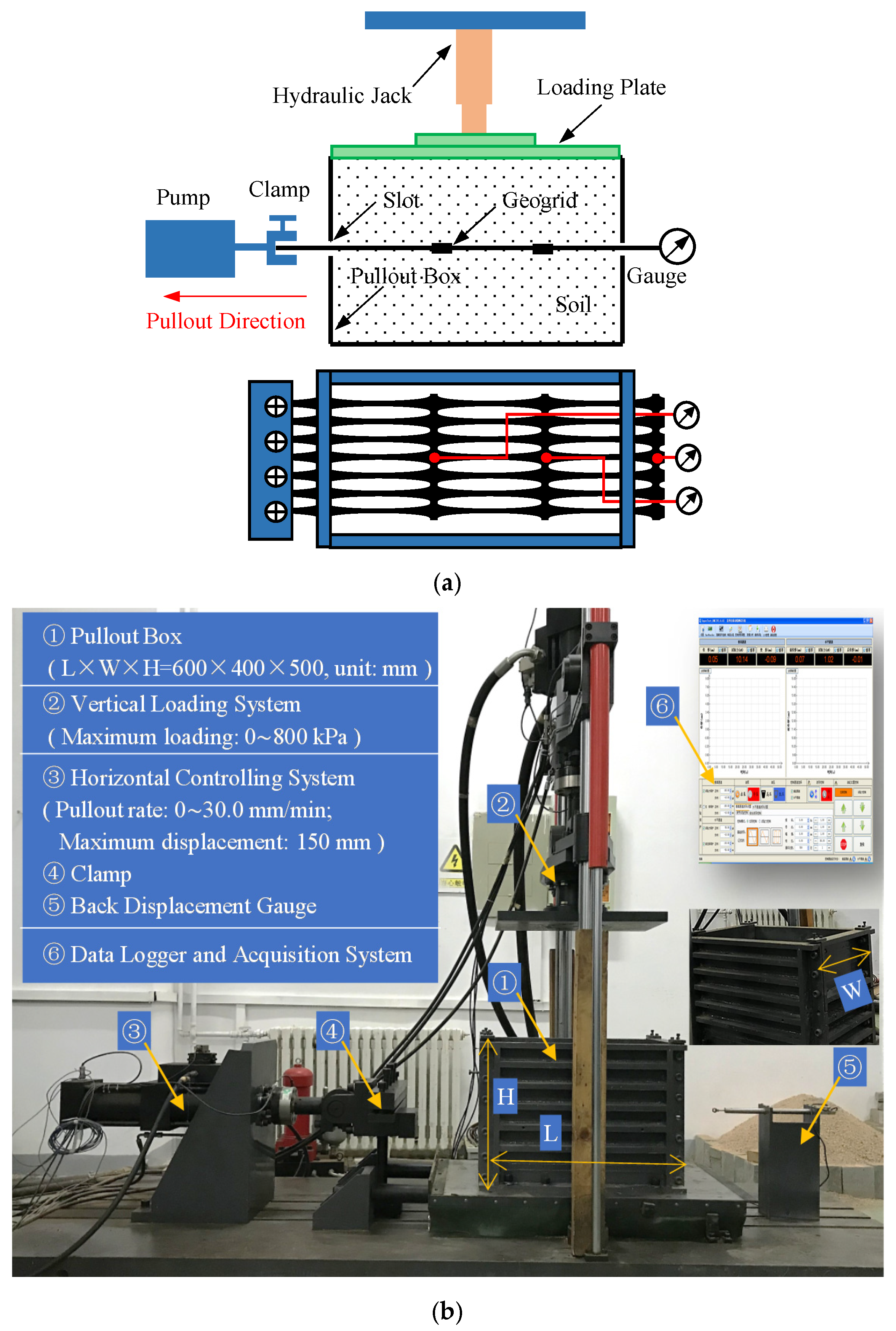
The large-scale pullout equipment utilized in this study was developed by Shijiazhuang Tiedao University. The pullout apparatus was mainly composed of four parts, pullout box, vertical controlling system, horizontal controlling system, data acquisition and logger system. The pullout box was built of steel and was 600 mm in length, 400 mm in width, and 500 mm in height on the inside dimensions. The vast dimensions of the pullout box can reduce the effect of the dimension of specimen and boundary effect for the duration of the test. In addition, to enhance the rigidity of the test box, the longitudinal members made of steel were added uniformly on the outside of the pullout box with the thickness of 10 mm to ensure the plane strain condition in the process of test. The vertical loading was applied by an inverted hydraulic jack and transferred to geosynthetic composite soil by loading plate. The vertical stress applied by the apparatus can reach 800 kPa and be monitored by a pressure sensor to keep it constant during the loading process, and the precision is 0.01% F.S. The pullout force in the horizontal direction was applied by the horizontal controlling system. The horizontal controlling system of pullout apparatus adopted the strain control type. The pullout rate varied from 0 to 30.0 mm/min, and the maximum pullout displacement can reach 150 mm, and the precision is ±0.02 mm. The maximum horizontal pullout force can reach 100 kN, and the precision is 0.01% F.S. At last, the test data can be displayed on the data acquisition and logger system in real-time, to enhance the control of the test progress. The schematic and view of the laboratory pullout apparatus and the main technical parameters corresponding to the components were shown in Figure 2.

2.2. Tested Materials

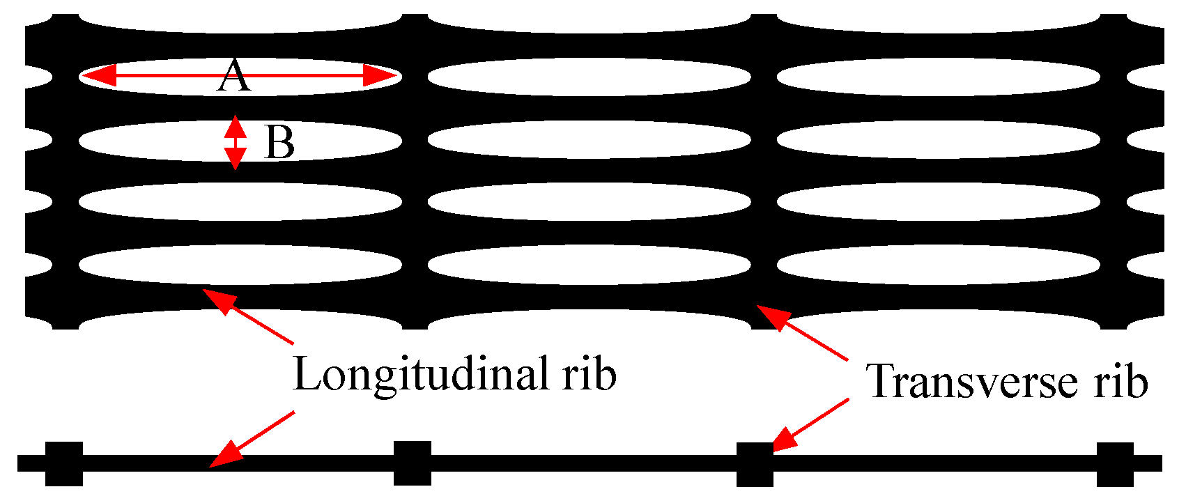
The geosynthetic used in the current research was a uniaxial geogrid composed of HDPE, as shown in Figure 3. The distance between two transverse ribs was 25 cm. The inner hole size of A, B was 235 and 14 mm, respectively. The thickness of the transverse rib was 3 mm. The tensile strength at failure, 2% strain, and 5% strain was 98.38, 31.15, and 58.23 kN/m, respectively.
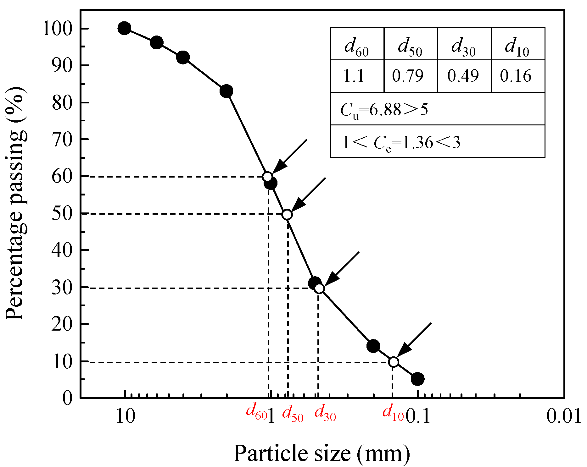
In this investigation, coarse sand was employed as infill material. According to ASTM D6913/D6913M-17, the curve of the grain size distribution of coarse sand was obtained using sieve analysis, as shown in Figure 4. From Figure 4, it can be observed that the particle size distribution of the coarse sand was varying from 0.1 to 10 mm, and the d10, d30, d50, d60 were 0.16, 0.49, 0.79, and 1.1 mm, respectively. Therefore, the coefficient of uniformity (Cu) and the coefficient of curvature (Cc) of the infill material used in this study were 6.88 and 1.36, respectively. Because Cu was larger than six and Cc was between one and three, it was determined that the filling material utilized in the experiment was judged to be well-graded sand. Hence, the coarse sand was classed as well graded soil (GW), in accordance with the Unified Soil Classification System (USCS) (ASTM D2487-11). Direct shear tests were also performed on specimens having a height of 20 mm and an interior size of 61.8 mm. The shear strength index of the coarse sand used in this research was obtained. The internal friction angle at Dr of 45% was 26.5 degrees.
The flexible boundary condition was created by flexible rubber [32] in the current study. It had the characteristics of low hardness, easy deformation, and can withstand high pressure that up to 8 MPa. Moreover, the Poisson’s ratio of the flexible rubber material was closed to 0.49, namely the volume was almost incompressible. In the pullout test process, the flexible rubber can transfer the upper load to the soil sample uniformly and can be deformed with the deformation of the soil sample surface. In this current study, the flexible rubber was attached on the positive of the inside test box and the lower side of the loading plate to simulate the flexible positive boundary condition and flexible top boundary condition, respectively.

2.3. Experimental Program

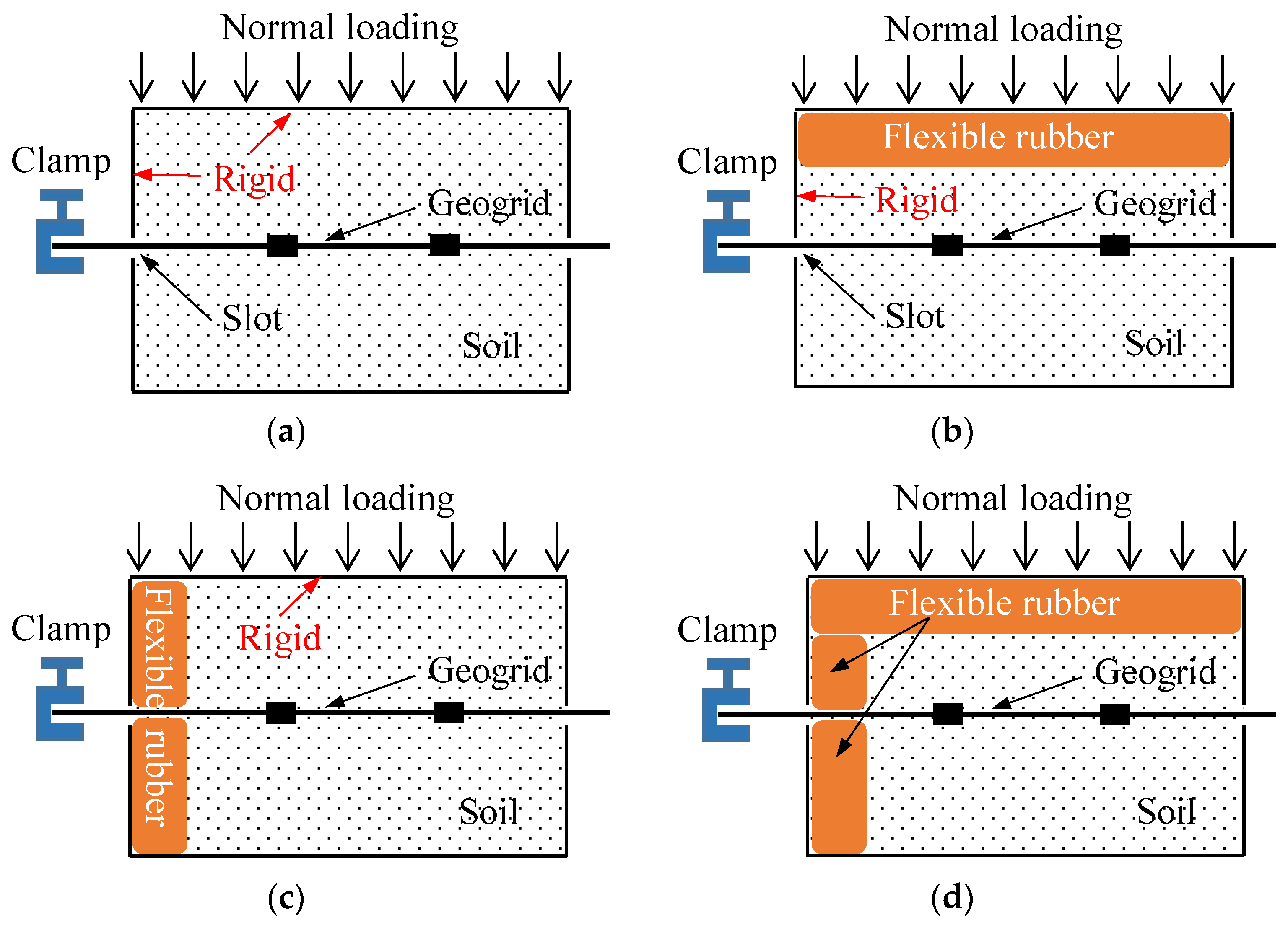
The content of the experimental program was presented in Table 1, Figure 5, respectively. In order to simplify the representation of different boundary conditions, a naming method was defined. For the 16 tests listed in Table 1, the first letter of representation, T, denotes the top boundary; the second letter, namely in the bracket, R or F, denotes the conditions corresponding to the top boundary; the third letter, P, denotes the positive boundary; the fourth letter, namely in the bracket, R or F, denotes the conditions corresponding to the positive boundary. Hence, T(R)&P(R) represents that the top boundary condition is rigid, and the positive boundary condition is rigid. T(F)&P(F) represents that the top boundary condition is flexible, and the positive boundary condition is flexible.

3. Results and Discussion

This section reviewed and discussed the experimental data and comments gained from laboratory pullout tests of HDPE geogrid-reinforced coarse sand subjected to various combinations of boundary conditions. Firstly, the effect of different boundary conditions, including top and positive, on the mechanical characteristics of the geogrid–soil interface were investigated. Meanwhile, with the rise in the normal stress, the effect of boundary condition on the evolution of the pullout resistance was also evaluated. Then, the curve characteristics of pullout test, and the variation laws of the growth pattern of pullout resistance of the geogrid–soil interface under different boundary conditions were analyzed. Finally, the interfacial shear strength characteristic of the reinforced interface, such as apparent cohesion and friction angle, subjected to different boundary conditions were also discussed.

3.1. Effect of Boundary Conditions on the Mechanical Response of the Geogrid–Soil Interface

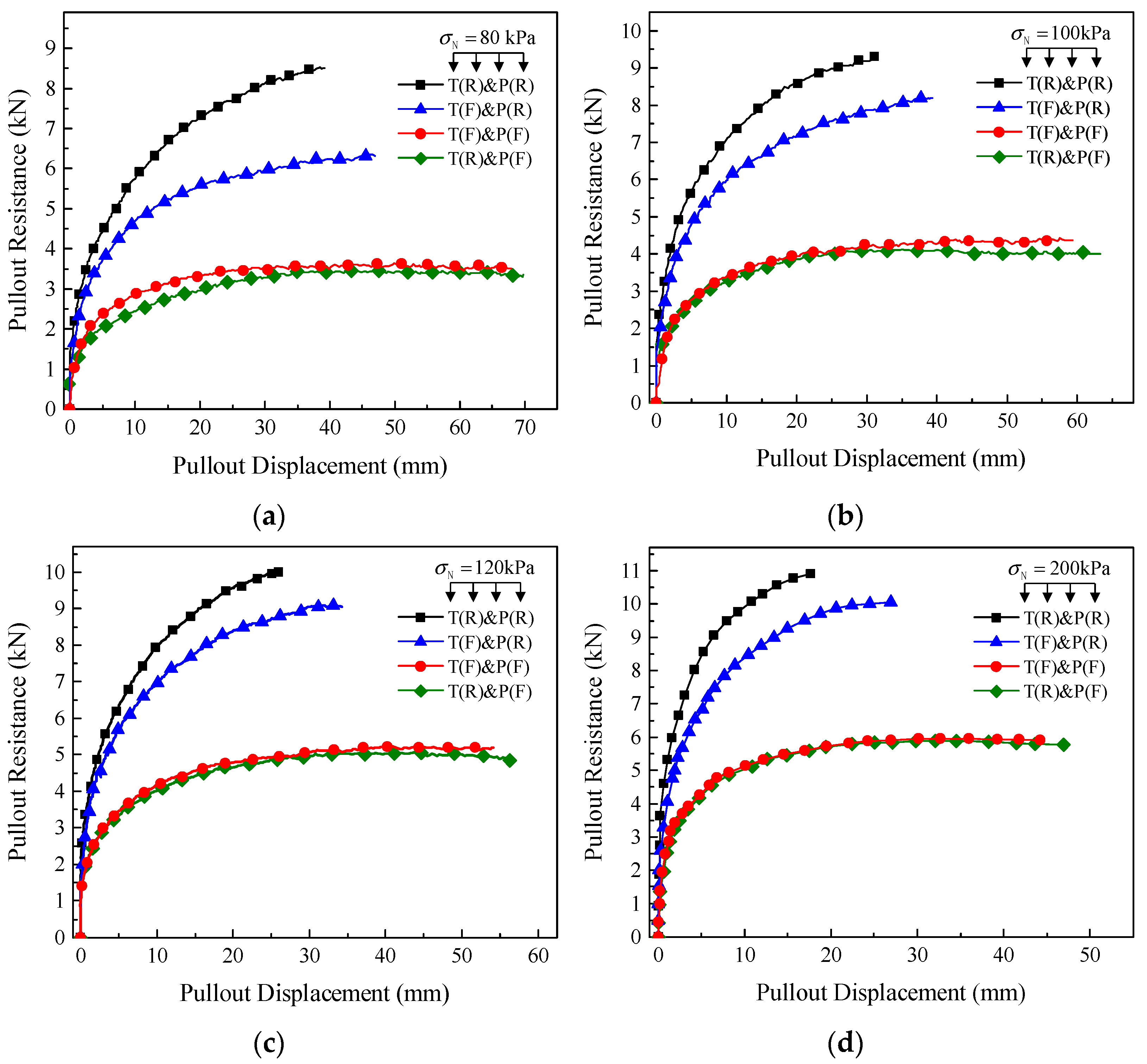
Figure 6 depicted a plot of pullout displacement vs. pullout resistance derived from pullout testing of HDPE uniaxial geogrid-reinforced coarse sand under various boundary conditions.
The curve of pullout displacement-pullout resistance with varied boundary conditions practically coincided in the beginning stage of the pullout test under the same normal loading, as shown in Figure 6. This demonstrated that when the pullout displacement was minor, the stiff and flexible boundary conditions of the top and positive end had an insignificant effect on the friction characteristics of the reinforced interface. The reason was that due to the small relative displacement, the boundary conditions had not yet worked, the potential energy produced by the interaction of the geogrid–soil was insignificant.
However, with the gradual rise in the pullout displacement, the curve of the pullout test with different boundary conditions began to present different effects, and the effect became more and more significant. For example, under the vertical loading of 100 kPa, the pullout resistance under the combination of top rigid boundary and positive rigid boundary condition (T(R)&P(R)) was the largest among the four types of boundary conditions, and then the pullout results under the combination of top flexible boundary and positive rigid boundary condition (T(F)&P(R)). Last was the pullout results under the combination of top rigid boundary and positive flexible boundary condition (T(R)&P(F)), the combination of top flexible boundary and positive flexible boundary condition (T(F)&P(F)). The experimental results of lab pullout test showed that the combination of top and positive boundary conditions had a noticeable influence on the mechanical response of reinforced interface. Thus, the boundary conditions cannot be ignored while designing and analyzing reinforced soil structures. In addition, the difference in pullout resistance between T(R)&P(F) and T(F)&P(F) was insignificant. Meanwhile, the pullout test curve presented a trend from hardening to softening with the change of boundary conditions from rigid to flexible. The reason was that under rigid boundary condition, the reinforcement was pulled out at a zero displacement and generally subjected to additional stress during the test. However, the additional stress was gradually decreased when the boundary condition changed from rigid to flexible.
Considering the complexity of the combination of the boundary conditions, based on the principle of the single variable, the influence of top and positive boundary conditions on the friction properties of interface was analyzed, respectively. Under the normal loading of 100 kPa, both the positive boundary condition was rigid, namely P(R). When the top boundary condition ranging from rigid to flexible, the pullout resistance changed from 9.20 to 8.199 kN, with a decrease of 10.88%. In the same way, both the top boundary condition was rigid, namely T(R). When the positive boundary condition ranging from rigid to flexible, the pullout resistance changed from 9.20 to 4.123 kN, with a decrease of 49.71%. Stress concentration was the responsible that the pullout resistance of geogrid under rigid positive boundary condition was greater than that of flexible positive boundary condition. In addition, the flexible boundary condition can redistribute the interaction force between the infill materials and the inner wall of test box or loading plate, then reducing the potential energy. On the contrary, under the normal stress of 100 kPa, both the positive boundary condition was flexible, namely P(F). When the top boundary condition ranging from rigid to flexible, the pullout resistance changed from 4.123 to 4.421 kN, with an increase of 7.23%. In the same way, both the top boundary condition was flexible, namely T(F). When the positive boundary condition ranging from rigid to flexible, the pullout resistance changed from 8.199 to 4.421 kN, with a decrease of 46.10%.
From the above analysis for the lab pullout tests under various boundary circumstances, it was observed that the effect of the positive boundary condition on the mechanical properties of the interface was significantly greater than that of the top boundary condition, which was consistent with the results obtained from Wang [18] and Sugimoto [29], also indicating the effectiveness of flexible rubber adapted to simulate flexible boundary in the current study. Next, the difference of the top boundary condition ranging from rigid to flexible under rigid positive boundary was slightly greater than that of the flexible positive boundary (10.88% > 7.23%). In the same way, the difference of the positive boundary condition ranging from rigid to flexible under rigid top boundary was less than that of the top flexible boundary (49.71% > 46.10%). It was proven again that the influence of the positive boundary condition was greater than that of the top boundary condition.
The reason was that the particles of the geogrid–soil interface would move along with the geogrid during the test, such that the particles would interact with the positive wall of the test box. However, if the inner positive wall of test box was a rigid boundary, its stiffness was far greater than that of the infill materials, and the positive wall of test box would not deform when the particles were interacting with the positive wall. Therefore, a large number of particles would accumulate at the positive wall when the geogrid moved along the pullout direction. With the increase of the density of particles close to the positive wall, the pullout resistance monitored by the data acquisition system increased. On the contrary, if the inner positive wall of the test box was a flexible boundary, the force offered by the geogrid would make the particle move and rotate when the particles were interacted with the positive wall, redistributing stress concentration closed to the positive boundary, and then reducing the potential energy.
From the above analysis, it was determined that the pullout resistance under positive rigid boundary measured by the sensor could not truly reflect the mechanical response of the reinforced interface. Therefore, the increment of pullout resistance caused by the stress concentration at the positive wall of test box should be subtracted to be regarded as the real pullout resistance of the reinforced soil interface. The flexible positive boundary can effectively reduce the effect of stress concentration. Based on the above analysis, the positive flexible boundary condition can simulate and reproduce the mechanical characteristics of the geogrid–soil interface in the actual reinforced structure. Hence, the pullout test results under the positive flexible boundary condition should be taken as the basis when designing reinforced structures. In addition, the effect of the positive boundary was greater than that of the top boundary. The reason was that the positive boundary had dissipated most of the internal force of the particles, the potential energy of the particles was low when the particles move to the top boundary.
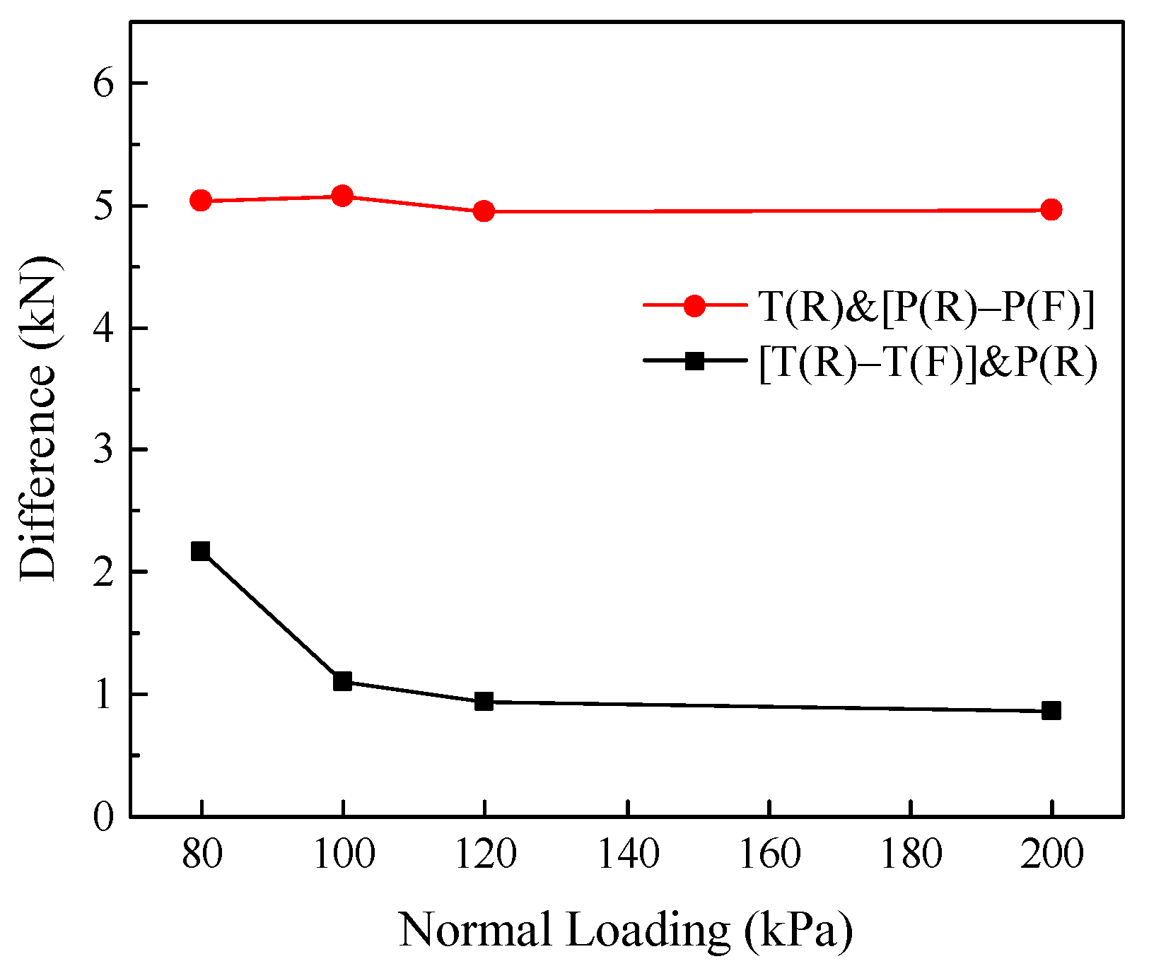
Additionally, from Figure 6, with the rise in the normal loading, the variation in pullout resistance between T(R)&P(R) and T(F)&P(R) was gradually decreased. However, the difference in pullout resistance between T(R)&P(R) and T(R)&P(F) was not obvious. To quantitatively analyze the impact of top and positive boundary conditions on the difference in pullout resistance with the rise in the normal loading, the results of tests were analyzed. The plot of the difference of pullout resistance subjected to various boundary circumstances was presented in Figure 7.
From Figure 7, under top rigid boundary condition, the difference of pullout resistance between rigid and flexible positive boundary was almost kept constant about 5 kN with the increase of the normal loading. However, under the positive rigid boundary condition, the difference of pullout resistance between rigid and flexible of the top boundary was gradually decreased and tended to be constant at 0.9 kN. From the above analysis, in the reinforced soil structures with rigid facing panel, the effect of top boundary conditions upon the pullout resistance was gradually decreased and tended to be constant. Moreover, the vertical stress can be regarded as the gravity of infill materials; thus, the height of infill materials above the reinforcements should be taken into account while designing reinforced soil structures.
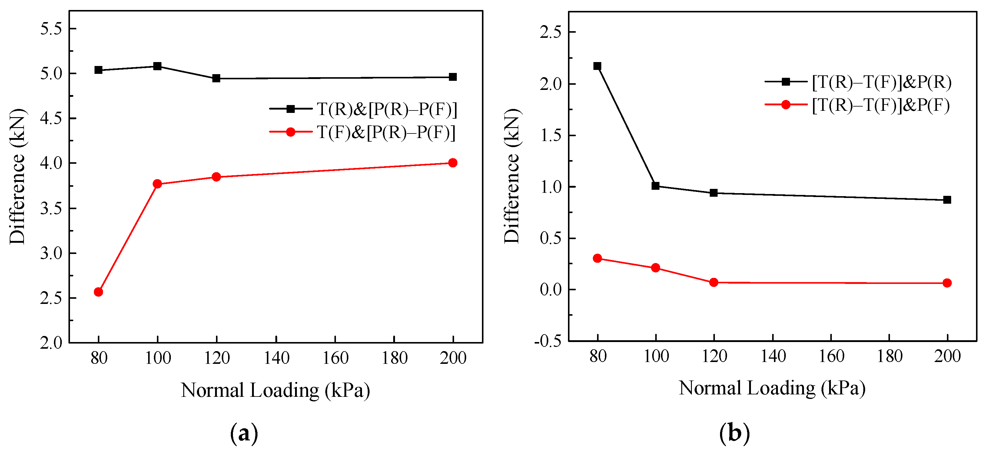
In practical engineering, the reinforced earth structures were mainly subjected to the coupling effect of the top and positive boundary condition. In addition to a single boundary condition, the influence of the coupling effect of the boundary conditions on the mechanical response of the geogrid–soil interface was also analyzed in the current study. From Figure 8, with the rise in the normal stress, a common characteristic was that the difference tended to be constant. The effect of the top rigid boundary condition on the difference between P(R) and P(F) was larger than that of the top flexible boundary condition. The top flexible boundary condition can ensure that the vertical loading on the soil sample was more uniform than rigid. However, according to the above conclusion, the effect of top boundary conditions on the mechanical behavior gradually decreased and tended to be constant with the increase of normal loading. Hence, the difference of T(R)&(P(R)-P(F)) and T(F)&(P(R)-P(F)) tend to be constant with increasing of the vertical loading. In the same way, the effect of positive rigid boundary condition on the difference between T(R) and T(F) was larger than that of the positive flexible boundary condition. Hence, the difference of (T(R)-T(F))&P(R) and (T(R)-T(F))&P(F) tend to be constant with increasing of the vertical loading.
At present, the boundary condition of the pullout apparatus was generally rigid at domestic and abroad. However, the flexible boundary condition can imitate and duplicate the mechanical properties of the reinforced interface in the real reinforced structure. As a result, the link between rigid and flexible boundary conditions had to be established in order to offer a reference for the construction of the reinforced soil structure. In the current study, the boundary reduction coefficient (BRC) was introduced to discuss the effect and variation laws of top or positive boundary condition on the mechanical behavior of the geogrid–soil interface.
B R C - * = P T ( * ) & P ( * ) P T ( R ) & P ( R )
where the BRC-* is the reduction coefficient of the corresponding boundary, BRC-T is the boundary reduction coefficient when the top is the flexible boundary; BRC-P is the boundary reduction coefficient when the positive is the flexible boundary; BRC-T&P is the boundary reduction coefficient when the top and positive are both flexible boundary; P T ( * ) & P ( * ) is the pullout resistance under top flexible or positive flexible boundary condition; P T ( R ) & P ( R ) is the pullout resistance under top rigid and positive rigid boundary condition.
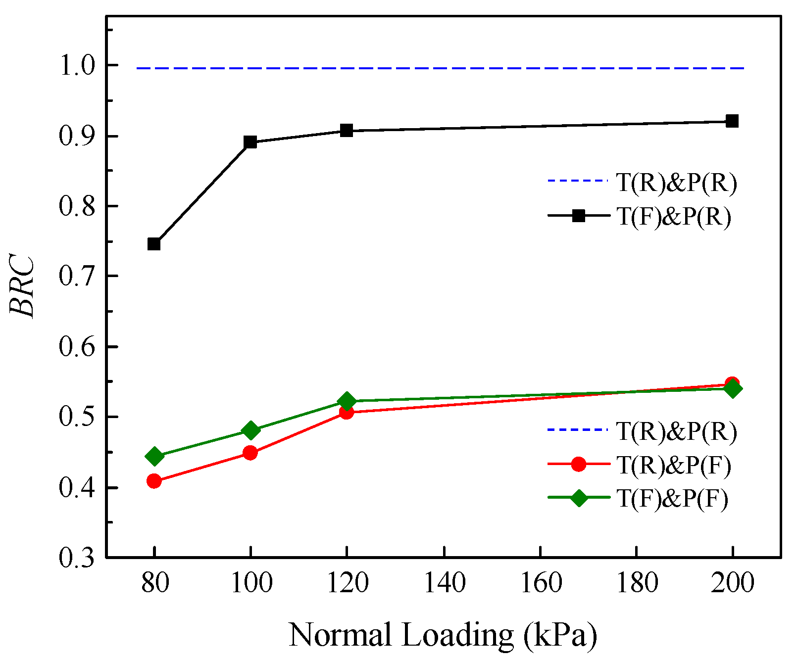
Figure 9 showed the variation laws of the boundary reduction coefficient (BRC) of the top and positive boundary condition. From Figure 9, both the top and positive boundary affected the pullout resistance, at the same time the BRC-T was larger than that of the BRC-P. With regard to the top boundary condition, the BRC-T was 0.745 under 80 kPa. However, the BRC-T tended to be constant for 0.90 with the increase of the normal loading. It was determined that the pullout resistance should be reduced for the reinforced structures with different top boundaries, and the determination and selection of BRC-T need to consider the height of the reinforced soil structure.
In this study, the normal critical loading was 100 kPa. The natural gravity of soil is generally 20 kN/m3. When the normal loading was up to 100 kPa (about a height of 5 m), the BRC-T can be taken as 0.9, which could be used to design reinforced soil structures. With regard to positive boundary condition, the BRC-P was 0.409 under 80 kPa. The BRC-P increased from 0.45 to 0.51, 0.55 with the rise in the normal stress. Although the BRC-P increased with the rise in the normal loading, the increment decreased. Hence, when the normal loading was up to 120 kPa (about a height of 6 m), the BRC-P can be taken as 0.5. In contrast, when the normal loading was less than 120 kPa, the BRC-P should be determined by the test. From Figure 9, the BRC-T&P was also presented. However, the difference between BRC-P and BRC-T&P was small. It was proved again that the effect of the positive boundary condition was greater than that of the top boundary condition, especially under T(F)&P(F). Thus, in order to simplify the design of reinforced earth structure and ensure safety, the values of BRC-T&P and BRC-P were consistent.

3.2. Growth Pattern and Fitting of Pullout Resistance under Different Boundary Conditions

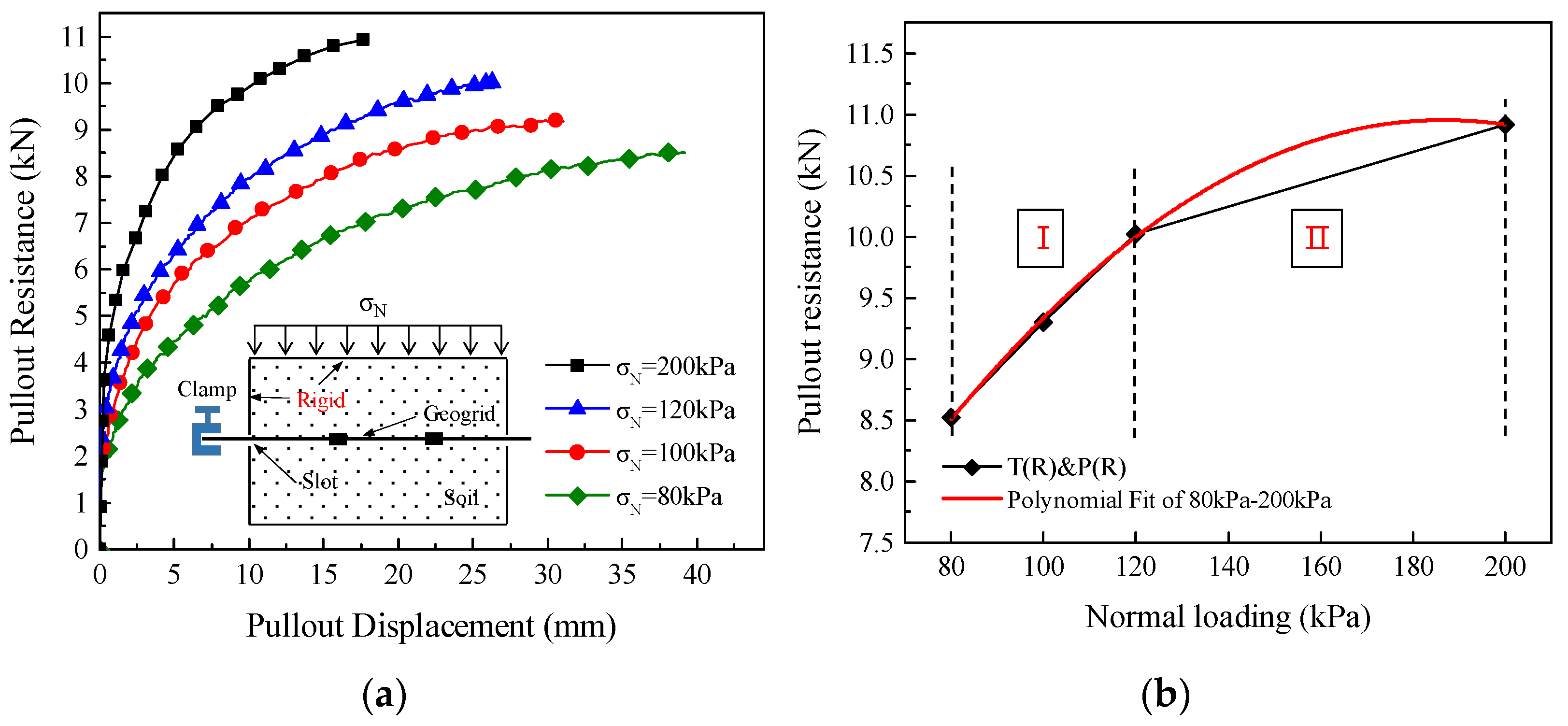
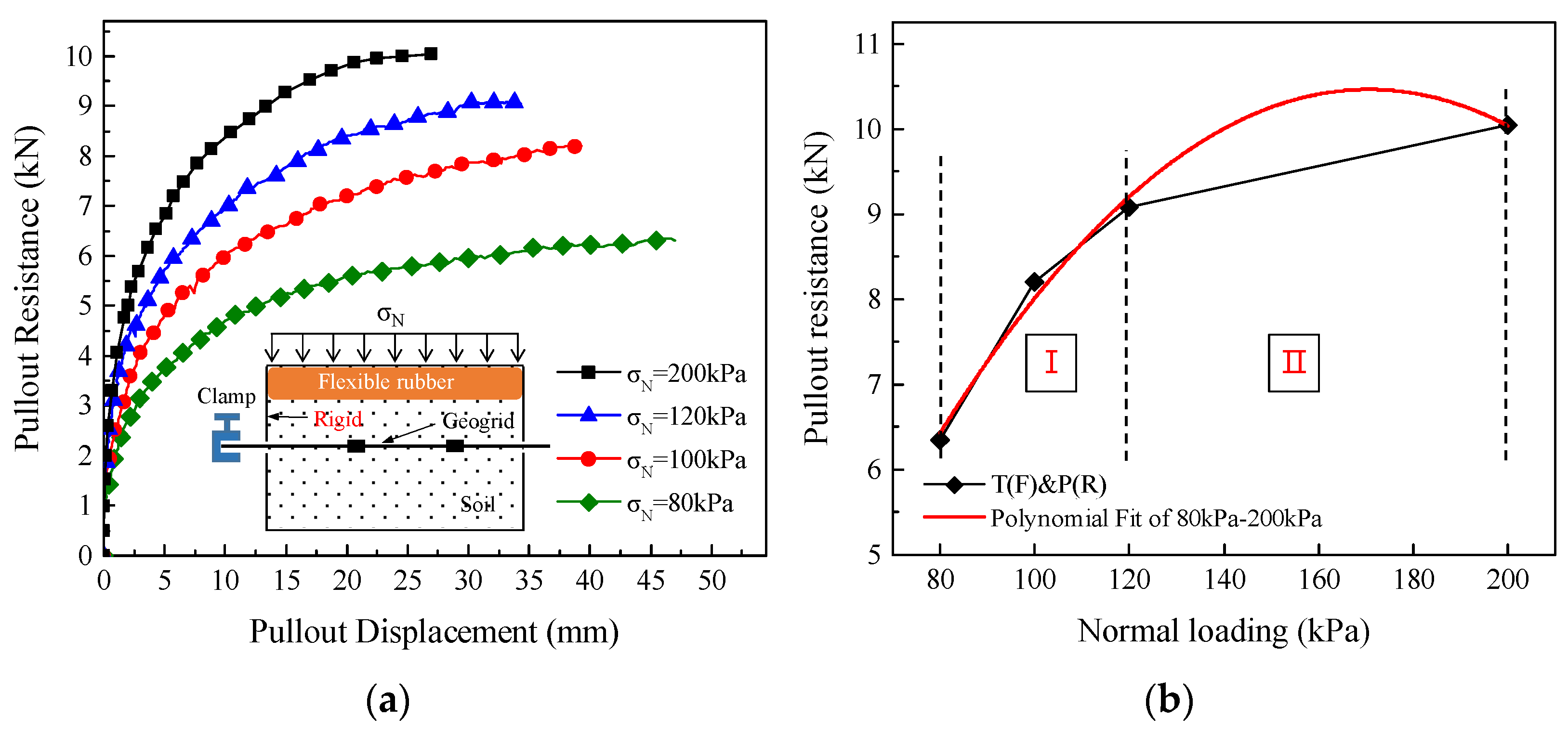
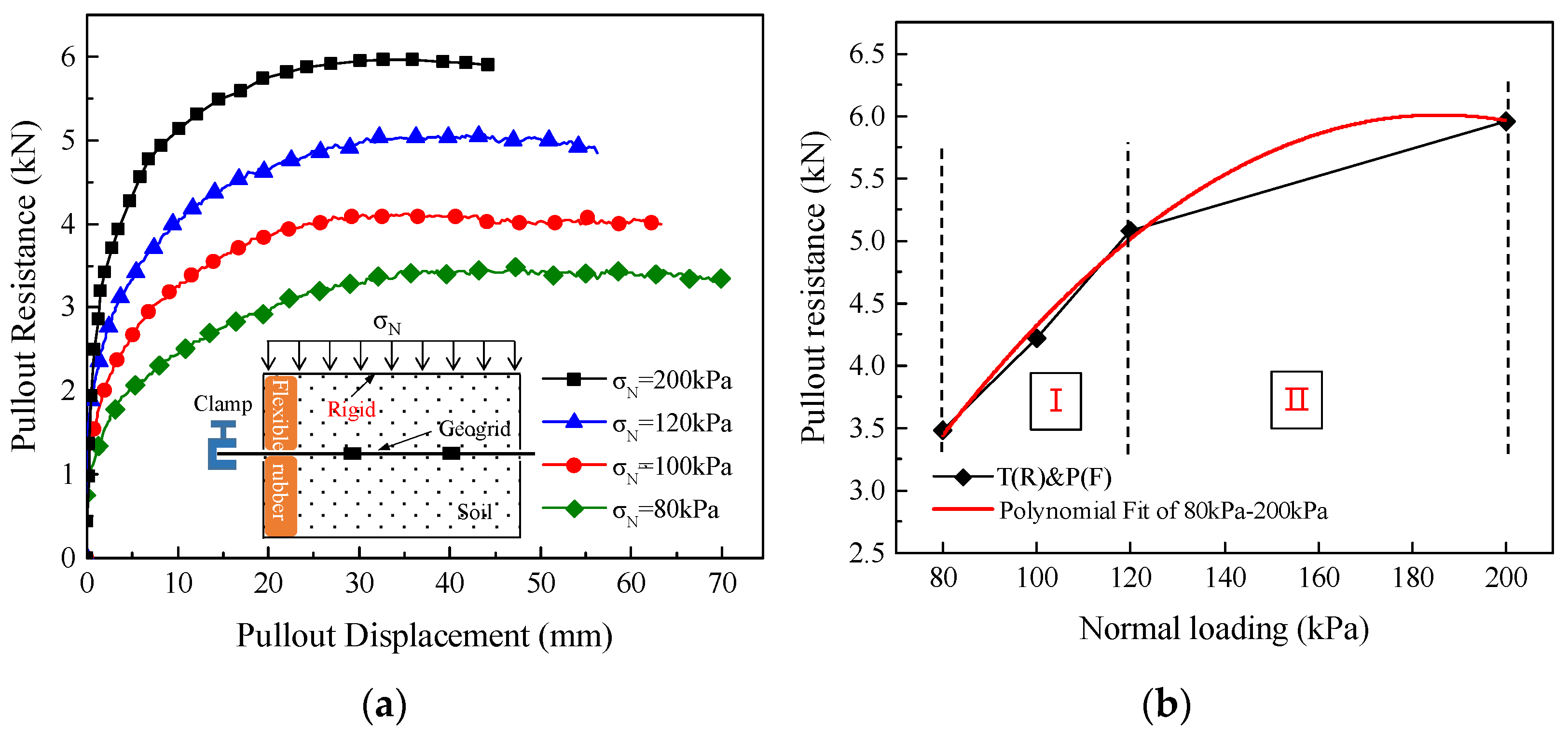
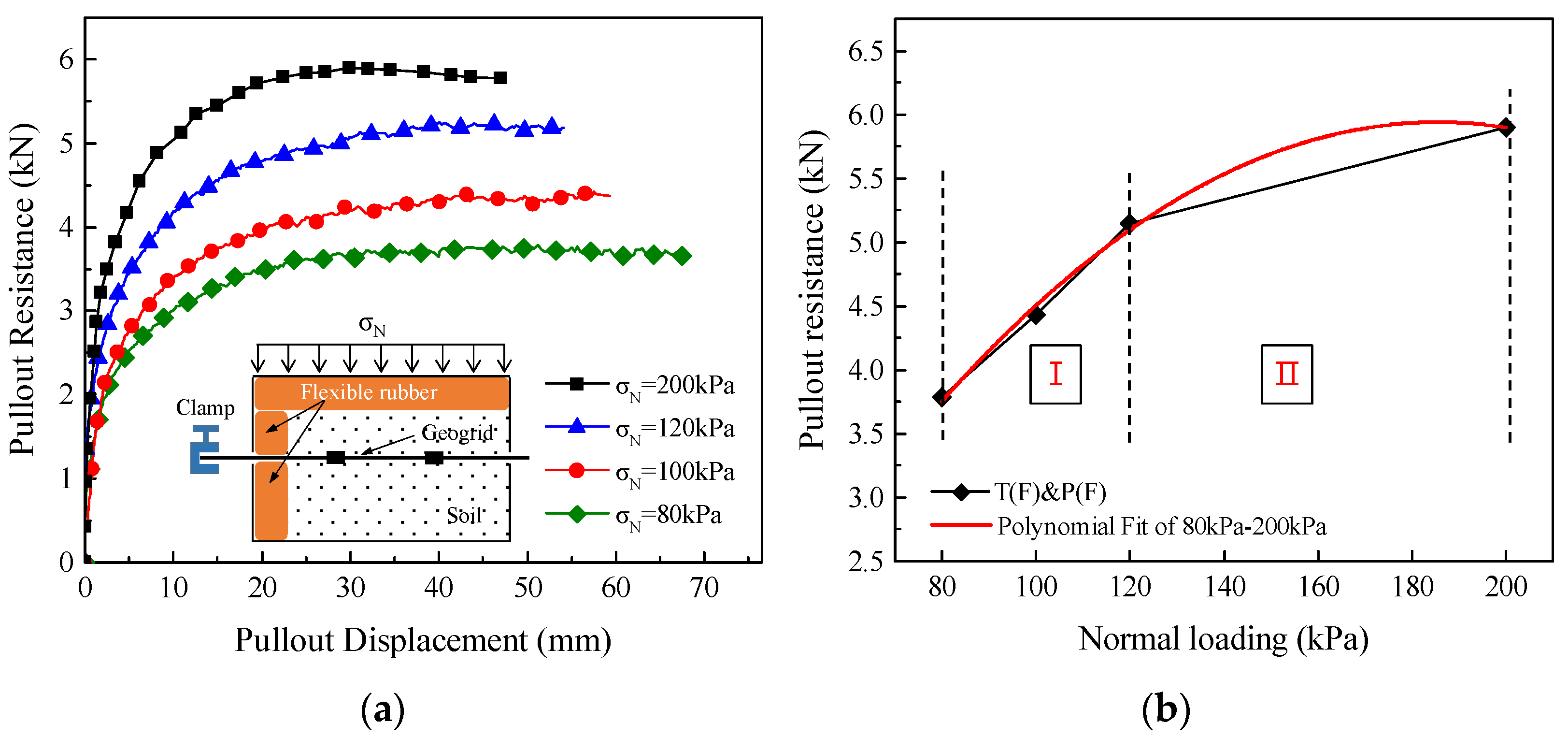
The plot of the pullout displacement vs. pullout resistance and the growth pattern of pullout resistance subjected to four types of boundary conditions were shown in Figure 10, Figure 11, Figure 12 and Figure 13, respectively. The curve of pullout resistance versus pullout displacement obtained from geogrid–soil interface under top rigid and positive rigid boundary condition (T(R)&P(R)) and top flexible and positive rigid boundary condition (T(F)&P(R)) presented strong strain-hardening behavior, as shown in Figure 10a and Figure 11a. In contrast, the curve characteristic of the reinforced interface under top rigid and positive flexible boundary condition (T(R)&P(F)) and top flexible and positive flexible boundary condition (T(F)&P(F)) presented slight strain-softening behavior, as shown in Figure 12a and Figure 13a. Moreover, it was found that the pullout resistance under four types of boundary conditions was directly proportional to the value of the normal stress and that the pullout resistance increased with the rise in the vertical stress.
With increasing of the normal loading, the growth patterns of the pullout resistance were almost similar under four types of boundary conditions, as presented in Figure 10b, Figure 11b, Figure 12b and Figure 13b, respectively. In accordance with the growth patterns, the pullout resistance could also be separated into two regions, such as region I and region II. In the region I, the pullout resistance under four types of boundary conditions was different, but the increment was almost the same, about 0.8 kN. In the region II, the growth rate of pullout resistance decreased obviously, but the pullout resistance was still showing an increasing trend. Hence, it can be concluded that the boundary conditions could affect the magnitude of pullout resistance, but the impact of boundary conditions upon the increment of pullout resistance was little.
In addition, the polynomial fitting was also used to analyze the relationship between the normal loading ranging from 80 to 200 kPa and the pullout resistance under four types of boundary conditions. The polynomial fitting curve and equations were shown in Figure 10b, Figure 11b, Figure 12b and Figure 13b and Table 2, respectively. According to the fitting equations, the maximum pullout resistance corresponding to the normal loading could be calculated. Under (T(R)&P(R)), the maximum pullout resistance was 10.90 kN, and the corresponding normal loading is 186.0 kPa. Under (T(F)&P(R)), the maximum pullout resistance was 10.88 kN, and the corresponding normal loading is 173.1 kPa. Under (T(R)&P(F)), the maximum pullout resistance was 5.981 kN, and the corresponding normal loading is 185.0 kPa. Under (T(F)&P(F)), the maximum pullout resistance was 5.986 kN, and the corresponding normal loading is 186.0 kPa.
Based on the above fitting results, the safety of the boundary reduction coefficient (BRC) obtained by Section 3.1 was also evaluated. Under the (T(F)&P(R)), the vertical loading corresponding to the maximum pullout resistance was 173.1 kPa, which was greater than 100 kPa. Hence, the BRC-T could be taken as 0.9. By reducing the results under (T(R)&P(R)), the maximum pullout resistance used for design was 9.81 kN under (T(F)&P(R)), which was less than the fitting results of 10.88 kN, and the safety factor was 1.1. Therefore, the BRC-T of the top boundary was reliable. Additionally, under the (T(R)&P(F)) and (T(F)&P(F)), the normal loading corresponding to the maximum pullout resistance was 185.0 and 186.0 kPa, which was both greater than 120 kPa. Hence, the BRC-P could be taken as 0.5. By reducing the results under (T(R)&P(R)), the maximum pullout resistance used for design was 5.45 kN under (T(R)&P(F)) and (T(F)&P(F)), which was both less than 5.981 and 5.986 kN, at the same time, the safety factor was 1.1. Thus, the BRC-P of the positive boundary was reliable. In addition, based on the results, it was observed that although the boundary conditions affect the pullout resistance of the geogrid–soil interface, the vertical loading corresponding to the maximum pullout resistance under different boundary conditions was about 180 kPa. Hence, it was concluded that the normal loading corresponding to the maximum pullout resistance was not related to boundary conditions.

3.3. Variation Laws of Interfacial Shear Strength Indexes Subjected to Different Boundary Conditions

The shear stress of the geogrid–soil interface could be calculated according to the Formula (2). The pullout test results under different boundary conditions were fitted, as presented in Figure 14. From Figure 14, it can be seen that the shear stress of geogrid–soil interface and normal stress showed a good linear relationship under different boundary conditions, and the correlation coefficients of the fitting were both 0.99.
τ g s = P T ( * ) & P ( * ) 2 B L
where the τg−s is the shear stress of the reinforced interface; B and L are the width and length of geogrid specimen in the test box, respectively.
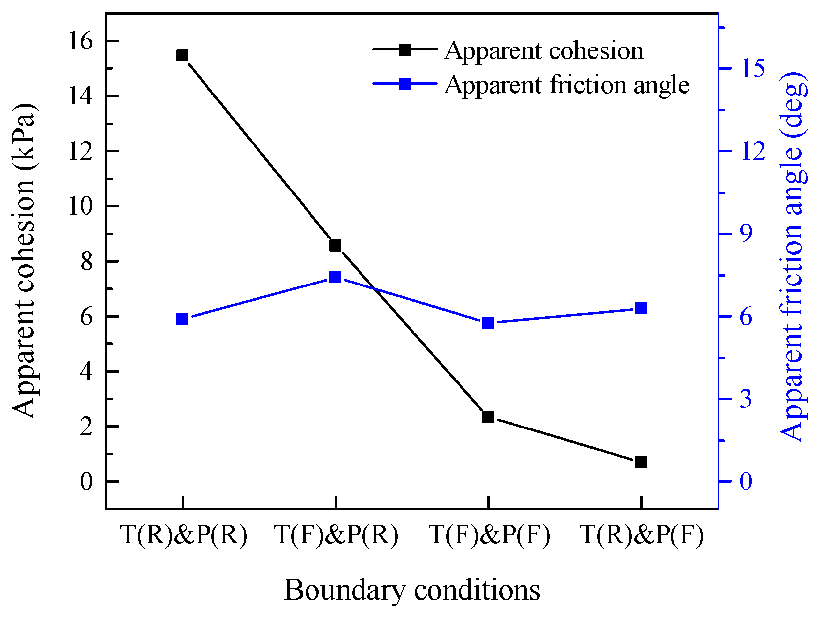
The equations of fitting, and shear strength characteristics of the geogrid–soil interface under four types of boundary conditions were presented in Figure 15 and Table 3, respectively. From Figure 15 and Table 3, the boundary conditions had a great influence on the apparent cohesion of the interface, but little influence on the apparent friction angle. Under T(R)&P(R), the apparent cohesion was the largest, which was 15.46 kPa. Then, the apparent cohesion under T(F)&P(R) was 8.56 kN. Last was T(R)&P(F) and T(F)&P(F), which were 2.34 and 0.68 kPa, respectively. In contrast to apparent cohesion, the variation range of the apparent friction angle under four types of boundary conditions was smaller, from 5.77 to 7.41°. The reason was that the relative density of soil close to the positive boundary increased during the pullout test, then increasing the apparent cohesion mainly offered by passive bearing capacity. The pullout resistance, apparent cohesion under flexible boundary condition was less than that of the rigid boundary condition. As a result, the pullout resistance matching to the boundary condition was determined in the design of the reinforced soil structure, according to the results of T(R)&P(R) and BRC. Then, the corresponding interface strength parameters were calculated to ensure the safety and durability of the reinforced earth structure.

4. Conclusions

This study used HDPE geogrid-reinforced coarse sand to conduct a series of lab pullout tests. The impacts of numerous parameters on the mechanical behavior of the geogrid–soil interface, including boundary conditions and normal loads, were investigated. Additionally, the boundary reduction coefficient (BRC) was obtained and verified by fitting results. The following conclusions were obtained.
(1) The mechanical behavior of the geogrid–soil interface was impacted by both the top and positive boundary conditions, with the positive boundary having a substantially bigger effect on pullout resistance than the top boundary condition. The track of particle movement and stress concentration was the responsible.
(2) With the rise in the normal loads, the effect of the top boundary decreased gradually. The flexible boundary should be taken for the design of structures, especially for positive. When the normal loading was up to 120 kPa, the BRC-T and BRC-P can be taken as 0.9 and 0.5, respectively.
(3) The pullout curve under (T(R)&P(R)) and (T(F)&P(R)) presented strong strain- hardening behavior, while (T(R)&P(F)) and (T(F)&P(F)) presented slight strain-softening behavior.
(4) The growth patterns of the pullout resistance were almost similar under four boundary conditions, and the pullout resistance could also be divided into two regions. The boundary conditions affect the pullout resistance, while the vertical loading matching the maximum pullout resistance was not related to boundary conditions.
(5) The apparent cohesion of the geogrid–soil interface was greatly affected by the boundary conditions, while the apparent friction angle was largely unaffected.
In this paper, the normal static loading was used in the test. In addition to static loading, the reinforced soil structures were generally subjected to dynamic loading. The follow-up work will study the influence of dynamic loading and boundary conditions on the geogrid–soil interface.

Author Contributions

Writing—original draft preparation, Z.Z.; writing—review and editing, G.Y.; validation, Z.W. and H.W.; funding acquisition, J.J. All authors have read and agreed to the published version of the manuscript.

Funding

This research was supported by the National Natural Science Foundation of China (NSFC) (grants Nos. 52079078 and 51709175), Scientific Research Foundation for the Returned Overseas Scholars of Hebei Province (grant No. CL201722), Natural Science Foundation of Hebei Province (grant No. E2018210097 and E2019208159), Science and Technology Research Projects of Universities in Hebei Province (grant No. QN2018255), and Scientific and Technological Research Projects of Colleges and Universities in Hebei Province (grant No. BJ2020045).

Institutional Review Board Statement

Not applicable.

Informed Consent Statement

Not applicable.

Data Availability Statement

The data used to support the findings of this study are available from the corresponding author upon request.

Conflicts of Interest

The authors declare no conflict of interest.

References

  1. Kim, Y.J.; Kotwal, A.R.; Cho, B.Y.; Wilde, J.; You, B.H. Geosynthetic reinforced steep slopes: Current technology in the United States. Appl. Sci. 2019, 9, 2008. [Google Scholar] [CrossRef] [Green Version]
  2. Zhang, W.; Du, D.; Bai, X.H. In Situ Testing of Square Footing Resting on Geobelt-Reinforced Gravel Thin Cushion on Soft Silt. Adv. Mater. Sci. Eng. 2018, 2018, 3563914. [Google Scholar] [CrossRef] [Green Version]
  3. Robinson, W.J.; Howard, I.L.; Tingle, J.S.; Norwood, G.J. Analysis of full-scale geosynthetic reinforced airfield pavement subjected to accelerated aircraft loading. J. Transp. Eng. Part B Pave. 2020, 146, 04020052. [Google Scholar] [CrossRef]
  4. Wang, X.; Ding, L.; Gao, W.; Zhang, M.; Fu, L. Research on Subgrade Differential Settlement Control Standard and Treatment Technology Based on Driving Comfort. Adv. Mater. Sci. Eng. 2020, 2020, 8956458. [Google Scholar] [CrossRef] [Green Version]
  5. Zhuang, Y.; Cui, X.Y.; Wang, K.Y.; Zhang, J. A simple design approach to analyse the piled embankment including tensile reinforcement and subsoil contributions. Geotext. Geomembr. 2021, 49, 466–474. [Google Scholar] [CrossRef]
  6. Burak, P.E.; Vefa, A.M. Comparison of Effects of Using Geosynthetics and Lime Stabilization to Increase Bearing Capacity of Unpaved Road Subgrade. Adv. Mater. Sci. Eng. 2016, 2016, 7129356. [Google Scholar]
  7. Wang, X.; Zhou, X.; Zhou, M.; Tian, Y. Behavior of large geotextile mat cofferdam with a new arrangement of geotextile reinforcement stiffness lying on soft sediments. Int. J. Geomech. 2020, 20, 04020121. [Google Scholar] [CrossRef]
  8. Sharma, V.; Kumar, A.; Kapoor, K. Sustainable deployment of crushed concrete debris and geotextile to improve the load carrying capacity of granular soil. J. Clean. Prod. 2019, 228, 124–134. [Google Scholar] [CrossRef]
  9. Luo, F.Y.; Huang, R.L.; Zhang, G. Centrifuge modeling of the geogrid-reinforced slope subjected to differential settlement. Acta. Geotech. 2020, 15, 3027–3040. [Google Scholar] [CrossRef]
  10. Altay, G.; Kayadelen, C.; Taşkıran, T.; Ziya, K.Y. A laboratory study on pull-out resistance of geogrid in clay soil. Measurement 2019, 139, 301–307. [Google Scholar] [CrossRef]
  11. Cardile, G.; Gioffre, D.; Moraci, N.; Calvarano, L.S. Modelling interference between the geogrid bearing members under pullout loading conditions. Geotext. Geomembr. 2019, 45, 169–177. [Google Scholar] [CrossRef]
  12. Aali, P.; Manoj, D.; Ramana, G.V.; Bansal, D. Measurement of Role of Transverse and Longitudinal Members on Pullout Resistance of PET Geogrid. Measurement 2019, 148, 106944. [Google Scholar]
  13. Li, F.L.; Ma, T.R.; Yang, Y.G. Numerical study on the rate-dependent behavior of geogrid reinforced sand retaining walls. Geomech. Eng. 2021, 25, 195–205. [Google Scholar]
  14. Jacobs, F.; Ruiken, A.; Ziegler, M. Investigation of kinematic behavior and earth pressure development of geogrid reinforced soil walls. Transp. Geotech. 2016, 8, 57–68. [Google Scholar] [CrossRef]
  15. Ke, H.; Ma, P.; Lan, J.W.; He, H. Field behaviors of a geogrid reinforced msw slope in a high-food-waste-content msw landfill: A case study. Geotext. Geomembr. 2020, 49, 430–441. [Google Scholar] [CrossRef]
  16. Xu, H.; Ren, X.; Chen, J.N.; Liu, C.N.; Xia, L.; Liu, Y.W. Centrifuge model tests of geogrid-reinforced slope supporting a high embankment. Geosynth. Int. 2019, 26, 629–640. [Google Scholar] [CrossRef]
  17. Zhang, J.; Liu, S.W.; Pu, H.F. Evaluation of an Improved Technique for Geosynthetic-Reinforced and Pile-Supported Embankment. Adv. Mater. Sci. Eng. 2015, 2015, 612760. [Google Scholar] [CrossRef] [Green Version]
  18. Kayadelen, C.; Önal, T.Ö.; Altay, G. Experimental study on pull-out response of geogrid embedded in sand. Measurement 2018, 117, 390–396. [Google Scholar] [CrossRef]
  19. Wang, Z.; Jacobs, F.; Ziegler, M. Experimental and DEM investigation of the geogrid-soil interaction under pullout loads. Geotext. Geomembr. 2016, 44, 230–246. [Google Scholar] [CrossRef]
  20. Park, K.; Kim, D.; Park, J.; Na, H. The Determination of pullout parameters for sand with a geogrid. Appl. Sci. 2021, 11, 11010355. [Google Scholar]
  21. Maleki, A.; Lajevardi, S.H.; Briançon, L.; Nayeri, A.; Saba, H. Experimental study on the L-shaped anchorage capacity of the geogrid by the pullout test. Geotext. Geomembr. 2021, 49, 1046–1057. [Google Scholar] [CrossRef]
  22. Abdi, M.R.; Arjomand, M.A. Pullout tests conducted on clay reinforced with geogrid encapsulated in thin layers of sand. Geotext. Geomembr. 2011, 29, 588–595. [Google Scholar] [CrossRef]
  23. Chen, J.F.; Gu, Z.A.; Rajesh, S.; Yu, S.B. Pullout Behavior of triaxial geogrid embedded in a transparent soil. Int. J. Geomech. 2021, 21, 04021003. [Google Scholar] [CrossRef]
  24. Abdi, M.R.; Mirzaeifar, H. Experimental and PIV evaluation of grain size and distribution on soil-geogrid interactions in pullout test. Soils Found. 2017, 57, 1045–1058. [Google Scholar] [CrossRef]
  25. Wang, J.; Liu, F.Y.; Zheng, Q.T.; Cai, Y.Q.; Gou, C.F. Effect of aperture ratio on the cyclic shear behaviour of aggregate-geogrid interfaces. Geosynth. Int. 2021, 28, 158–173. [Google Scholar] [CrossRef]
  26. Ghaaowd, I.; McCartney, J.S. Pullout of geogrids from tire-derived aggregate having large particle size. Geosynth. Int. 2020, 27, 671–684. [Google Scholar] [CrossRef] [Green Version]
  27. Zuo, Z.; Yang, G.Q.; Wang, Z.J.; Wang, H. Experimental investigations on pullout behavior of HDPE geogrid under static and dynamic loading. Adv. Mater. Sci. Eng. 2020, 2020, 5408064. [Google Scholar] [CrossRef]
  28. Cardile, G.; Pisano, M.; Moraci, N. The influence of a cyclic loading history on soil-geogrid interaction under pullout condition. Geotext. Geomembr. 2019, 47, 552–565. [Google Scholar] [CrossRef]
  29. Palmeira, E.M.; Milligan, G.W. Scale and other factors affecting the results of pull-out tests of grids buried in sand. Geotechnique 1990, 40, 519–521. [Google Scholar] [CrossRef]
  30. Sugimoto, M.; Alagiyawanna, A.M.N.; Kadoguchi, K. Influence of rigid and flexible face on geogrid pullout tests. Geotext. Geomembr. 2001, 19, 257–277. [Google Scholar] [CrossRef]
  31. Hsieh, C. Hsieh, M.W. Load plate rigidity and scale effects on the frictional behavior of sand/geomembrane interfaces. Geotext.Geomembr. 2003, 21, 25–47. [Google Scholar] [CrossRef]
  32. Wang, H.P.; Li, S.C.; Yue, X.L.; Wang, Q. Study on Design and Test of Flexible Uniform Pressure Loading Device. Adv. Sci. Lett. 2011, 4, 646–650. [Google Scholar] [CrossRef]
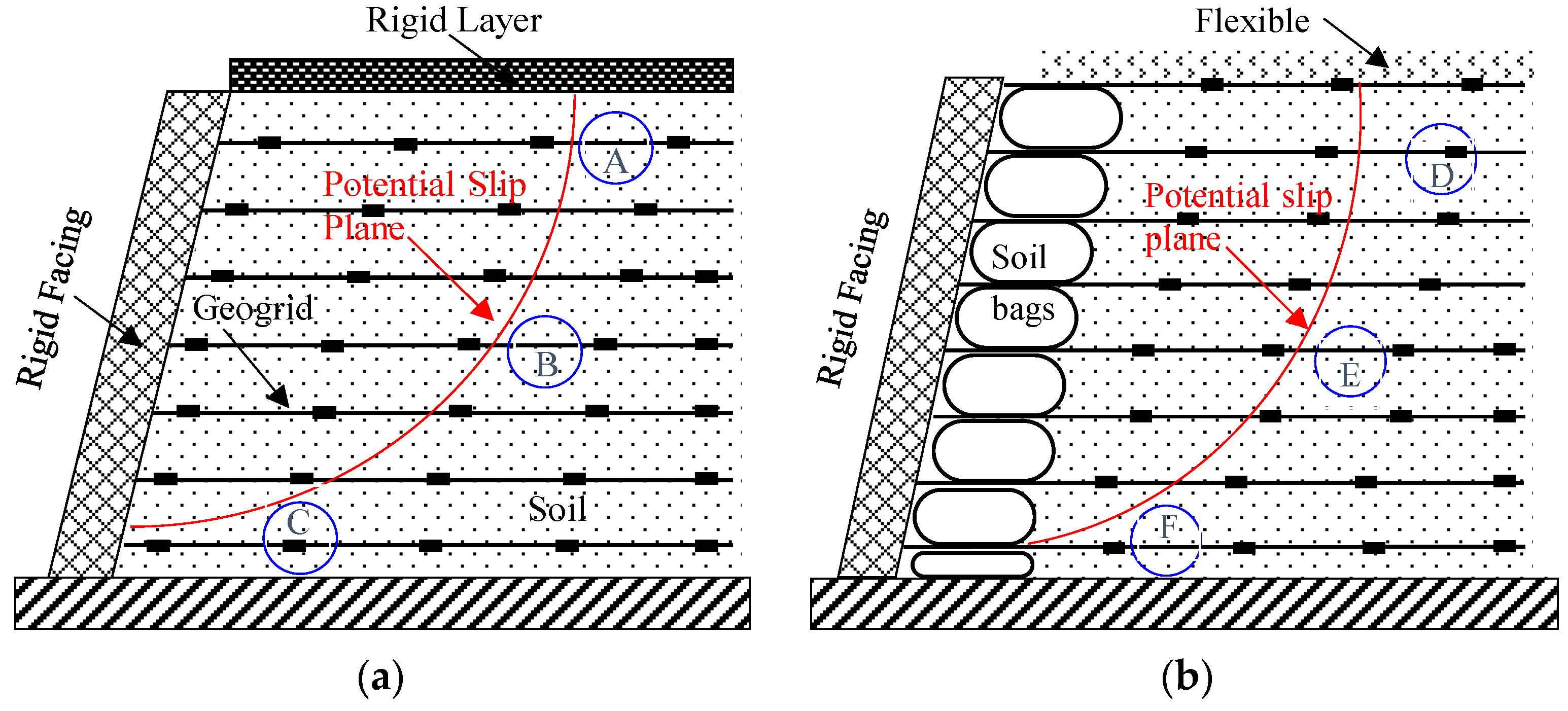
Figure 1. (a) Reinforced structures with top rigid and positive rigid; (b) reinforced structures with top flexible and positive flexible.
Applsci 11 09942 g001
Figure 2. (a) The schematic representation of pullout apparatus; (b) the view and technical parameters of pullout apparatus used in the current study.
Applsci 11 09942 g002
Figure 3. The schematic representation of the geogrid.
Applsci 11 09942 g003
Figure 4. The plot of particle size distribution.
Applsci 11 09942 g004
Figure 5. The representation schematic view of boundary conditions of the pullout tests: (a) both rigid with top and positive; (b) top flexible and positive rigid; (c) top rigid and positive flexible; (d) both flexible with top and positive.
Applsci 11 09942 g005
Figure 6. The plot of pullout displacement vs. pullout resistance derived from pullout testing of HDPE uniaxial geogrid-reinforced coarse sand under various boundary conditions: (a) 80 kPa; (b) 100 kPa; (c) 120 kPa; (d) 200 kPa.
Applsci 11 09942 g006
Figure 7. Difference of boundary conditions with the increase of normal loading.
Applsci 11 09942 g007
Figure 8. (a) Effect of top boundary conditions on the front boundary conditions; (b) effect of positive boundary conditions on the top boundary conditions.
Applsci 11 09942 g008
Figure 9. The plot of boundary reduction coefficient (BRC) of top and positive boundary.
Applsci 11 09942 g009
Figure 10. (a) The pullout displacement versus pullout resistance under T(R)&P(R); (b) the growth pattern of pullout resistance under T(R)&P(R).
Applsci 11 09942 g010
Figure 11. (a) The pullout displacement versus pullout resistance under T(F)&P(R); (b) the growth pattern of pullout resistance under T(F)&P(R).
Applsci 11 09942 g011
Figure 12. (a) The pullout displacement versus pullout resistance under T(R)&P(F); (b) The growth pattern of pullout resistance under T(R)&P(F).
Applsci 11 09942 g012
Figure 13. (a) The pullout displacement versus pullout resistance under T(F)&P(F); (b) the growth pattern of pullout resistance under T(F)&P(F).
Applsci 11 09942 g013
Figure 14. The plot of normal loading versus shear stress and linear fitting of shear stress.
Applsci 11 09942 g014
Figure 15. The variation laws of apparent cohesion and apparent friction angle under different boundary conditions.
Applsci 11 09942 g015
Table 1. Experimental program of the boundary conditions in this study.
NO.Top PositiveRepresentationNormal Loads (kPa)
1RigidRigidT(R)&P(R)80
2FlexibleRigidT(F)&P(R)
3RigidFlexibleT(R)&P(F)
4FlexibleFlexibleT(F)&P(F)
5RigidRigidT(R)&P(R)100
6FlexibleRigidT(R)&P(F)
7RigidFlexibleT(F)&P(R)
8FlexibleFlexibleT(F)&P(F)
9RigidRigidT(R)&P(R)120
10FlexibleRigidT(R)&P(F)
11RigidFlexibleT(F)&P(R)
12FlexibleFlexibleT(F)&P(F)
13RigidRigidT(R)&P(R)200
14FlexibleRigidT(R)&P(F)
15RigidFlexibleT(F)&P(R)
16FlexibleFlexibleT(F)&P(F)
Table 2. Polynomial fitting of pullout resistance under different boundary conditions.
Boundary ConditionsPolynomial Fitting Equation
T(R)&P(R)y = 3.456 + 0.08x − 2.15 × 10−4x2 (R2 = 0.99)
T(F)&P(R)y = −3.834 + 0.17x − 4.91 × 10−4x2 (R2 = 0.98)
T(R)&P(F)y = −1.906 + 0.085x − 2.29 × 10−4x2 (R2 = 0.98)
T(F)&P(F)y = −0.811 + 0.073x − 1.96 × 10−4x2 (R2 = 0.99)
Table 3. Shear strength parameters under four types of boundary conditions.
Boundary ConditionsFitting EquationApparent Cohesion/kPaApparent Friction Angle/Degree
T(R)&P(R)y = 0.103x + 15.46 (R2 = 0.99)15.465.88
T(F)&P(R)y = 0.111x + 8.56 (R2 = 0.99)8.567.41
T(F)&P(F)y = 0.101x + 2.34 (R2 = 0.99)2.345.77
T(R)&P(F)y = 0.110x + 0.68 (R2 = 0.99)0.686.28
where y is shear stress of the geogrid–soil interface, x is the normal loading.
Publisher’s Note: MDPI stays neutral with regard to jurisdictional claims in published maps and institutional affiliations.