Article

Model Test Study on Deformation Characteristics of a Fissured Expansive Soil Slope Subjected to Loading and Irrigation

1
Key Laboratory of Shale Gas and Geoengineering, Institute of Geology and Geophysics, Chinese Academy of Sciences, Beijing 100029, China
2
College of Earth and Planetary Science, University of Chinese Academy of Sciences, Beijing 100049, China
3
Innovation Academy of Earth Science, Chinese Academy of Sciences, Beijing 100029, China
4
China Institute of Geotechnical Investigation and Surveying, Beijing 100007, China
5
Beijing Zhongyan Tiandi Technology Co., Ltd., Beijing 100029, China
6
Yunnan Chuyao Expressway Construction Headquarters, Chuxiong 675000, China
*
Author to whom correspondence should be addressed.
Appl. Sci. 2021, 11(22), 10891; https://doi.org/10.3390/app112210891
Submission received: 9 October 2021 / Revised: 16 November 2021 / Accepted: 17 November 2021 / Published: 18 November 2021
(This article belongs to the Section Civil Engineering)

Abstract

:
Expansive soils are characterized by repeated swelling and shrinkage. They cause great damage to engineering projects because of their expansiveness, over-consolidation and propensity to crack. However, the impact of cracks on the stability of an expansive soil slope during loading and irrigation is not yet fully understood. This study aimed to investigate the relationship between slope state and crack development in fissured expansive soils. A series of physical model tests with different types of cracks were conducted, in which the fissured expansive soil slopes were subjected to different loadings (1.6, 3.2, 4.8, 6.4, 16 MPa), and irrigated at a flow rate of 25 mL/min. The VIC-2d software, which utilizes the digital image correlation principle, was used to quantitatively obtain the horizontal and vertical strain data of the slope model. The closure and opening of cracks, and the slope state after loading and irrigation were monitored by strain data analysis using VIC-2d software. The results indicate that the excessive overlying stress revives the existing cracks and produces sliding along the crack interface. The sliding surface of the fissured expansive soil slope became shallower due to the water infiltration. It was demonstrated that the middle and foot of the fissured expansive soil slope were the key positions for reinforcement from the perspective of the mutual transformation of tensile strain and compressive strain on the surface of the slope. It is of great importance to study the relationship between the crack strain state and deformation trend of a slope subjected to loading and infiltration to understand the progressive surface- or shallow-layer sliding mechanisms, and reinforce key areas of the slopes in areas containing moderately or strongly expansive soils with abundant cracks.

1. Introduction

Expansive soils are characterized by repeated swelling and shrinkage due to the layered crystal structure of clay minerals, e.g., smectite, illite, etc., and the adsorbed cations [1]. As a result, a large number of expansion and shrinkage cracks are produced in expansive soil. Expansive soils cause great damage to slope stability because of their expansiveness, over-consolidation, and propensity to crack. Thus, expansive soil is called “calamitous soil”. Expansive soils are widely distributed throughout the world, including the United States, Canada, Australia, India, and many other countries [2]. In China, expansive soils occur in >20 provinces, covering an area of 600,000 km2 [3]. Damage caused by expansive soil can be observed around the world. An economic loss of approximately USD 7–9 billion per year has been reported in the USA alone [4,5].
Recent studies have shown that the existence and the development of cracks in expansive soil have an important effect on the stability of expansive soil slopes. The presence of fissures or cracks near the ground surface is critical to the soil suction and water interaction [6,7]. The cracks tend to heal through horizontal growth due to preferential water movement, and reopen upon lateral contraction due to a weak connection with the clay matrix [8]. The shrinkage of expansive soil can cause the development of tensile stress and variations in water content along the fissures [9,10]. When tensile stress exceeds tensile strength, desiccation cracks will appear on the slope surface of expansive soil regardless of slope inclination, and especially on the crest of the slope. Desiccation fissures can initiate and propagate in expansive soil subjected to drying–wetting cycles. The fissures provide pathways for rainwater infiltration and evaporation to further reduce the shear strength [10,11]. The relationships between the geometric parameters of these cracks and the water content/drying time were presented to further quantify the three stages of crack development by a digital imaging method, i.e., the initial stage, the primary stage and the steady-state stage [11]. A digital imaging method was recently used to obtain images and the geometric parameters (i.e., crack porosity, crack aperture, and crack density) of clay-rich soils with desiccation cracks at the ground surface [11]. The relationship between the crack strain change and deformation trend of fissured expansive soil slopes has not yet been investigated. Three different irrigation methods, including spray irrigation, drip irrigation and surface irrigation, were used to study crack variation and flow rules in expansive soil by dye experiments. The results show that the cracks closed rapidly under surface irrigation but partially closed under spray irrigation, and the degree of crack closure decreased with the distance from the drip center under drip irrigation [12]. During freezing on the slope surface, the migration of water and the growth of ice crystals result in frost heave, the formation of cracks and alterations in the structure of expansive soil [13,14]. During thawing, the water content of expansive soil increases due to the inflow of snowmelt water, causing a decrease in the stiffness, strength and thaw settlement of expansive soil [14,15]. Methods such as sketching superficial cracks, drilling holes and non-destructive detection for verification can reflect the real distribution characteristics of interior cracks to a certain extent [16]. It is important to understand the distribution characteristics of cracks in expansive soil to study the mechanisms of expansive soil landslides.
Surface- or shallow-layer failure can easily occur in expansive soil slopes [6,17]. Different techniques can be used to research the mechanisms of slope failure during loading, rainfall or irrigation. A field test was carried out to study the influence of slope inclination and rainfall intensity on evaporation, infiltration and water content on both vegetated and bare slopes of expansive soil [10]. Numerical simulations have been used to combine deformation analysis and infiltration analysis [18,19,20,21], whereby the performance of an expansive soil slope under rainfall could be assessed. Reduced-scale model tests have been carried out in a 1 g condition [6,22] or in a centrifuge environment [23] where artificial rainfall was used to trigger a landslide. Digital image correlation (DIC) technology was used to quantitatively obtain horizontal and vertical deformation data of physical experiment. DIC technology was first proposed by Yamaguchi [24] and Ranson and Peters [25] in the early 1980s. This method is a non-contact measurement method that compares the digital image differences in samples before and after deformation, so as to calculate the strain field. DIC technology is widely used in the analysis of strain field distribution, deformation mode, progressive failure process and the sliding shear zone characteristics of rock or soil masses [26,27,28,29,30].
Great attention should be paid to avoiding the development of surface fissures and minimizing the amount of water infiltration in expansive soil slopes. Many studies have demonstrated that chemical stabilizers, such as fly ash, lime and cement, are widely used to modify and improve the hydro-mechanical characteristics of expansive soils [31]. The effect of coupling pond ash and polypropylene fiber has been investigated to control the strength and durability of expansive soil against tensile cracks [5,32]. Different capillary barrier systems have been proposed, such as the use of recycled crushed concrete and geosynthetics [5,33], recycled asphalt pavement wastes [34], waste tire textile fibers as reinforcement materials [35], residual soils as cover system [36] and soil bags [37,38].
Although extensive studies on the stability and improvement of expansive soil slopes have been carried out, the mechanism of the influence of cracks on the stability of an expansive soil slope during loading and irrigation is not yet fully understood. Field testing can be used to study the failure process of an expansive soil slope subjected to artificial rainfall. However, this kind of experiment is costly, takes a long time and the experimental data are highly discrete. The physical model test method is an alternative to research the stability of soil slopes in the laboratory, although the correct stress field of a soil slope cannot be reproduced. Loose granular materials can normally be used in most of the model tests due to the ease of triggering slide or flow [6]. However, the effect of cracks on slope stability cannot be considered in this method. In this study, a series of physical model tests with different types of cracks were conducted, in which the fissured expansive soil slopes were subjected to different loadings (1.6, 3.2, 4.8, 6.4, 16 MPa) and irrigated at a flow rate of 25 mL/min. The VIC-2d software, which utilizes the DIC principle, was used to quantitatively obtain the horizontal and vertical strain data of the slope model. The closure and opening of cracks, and the slope state after loading and irrigation were monitored by strain data analysis using VIC-2d software. The aim of this study was to investigate the relationship between the crack strain state and the deformation trend of a fissured expansive soil slope. The results of this research are of great importance in analyzing strain field distribution, deformation rule, progressive surface- or shallow-layer sliding mechanisms and key reinforcement areas for fissured expansive soil slopes.

2. Background and Specimen Preparation
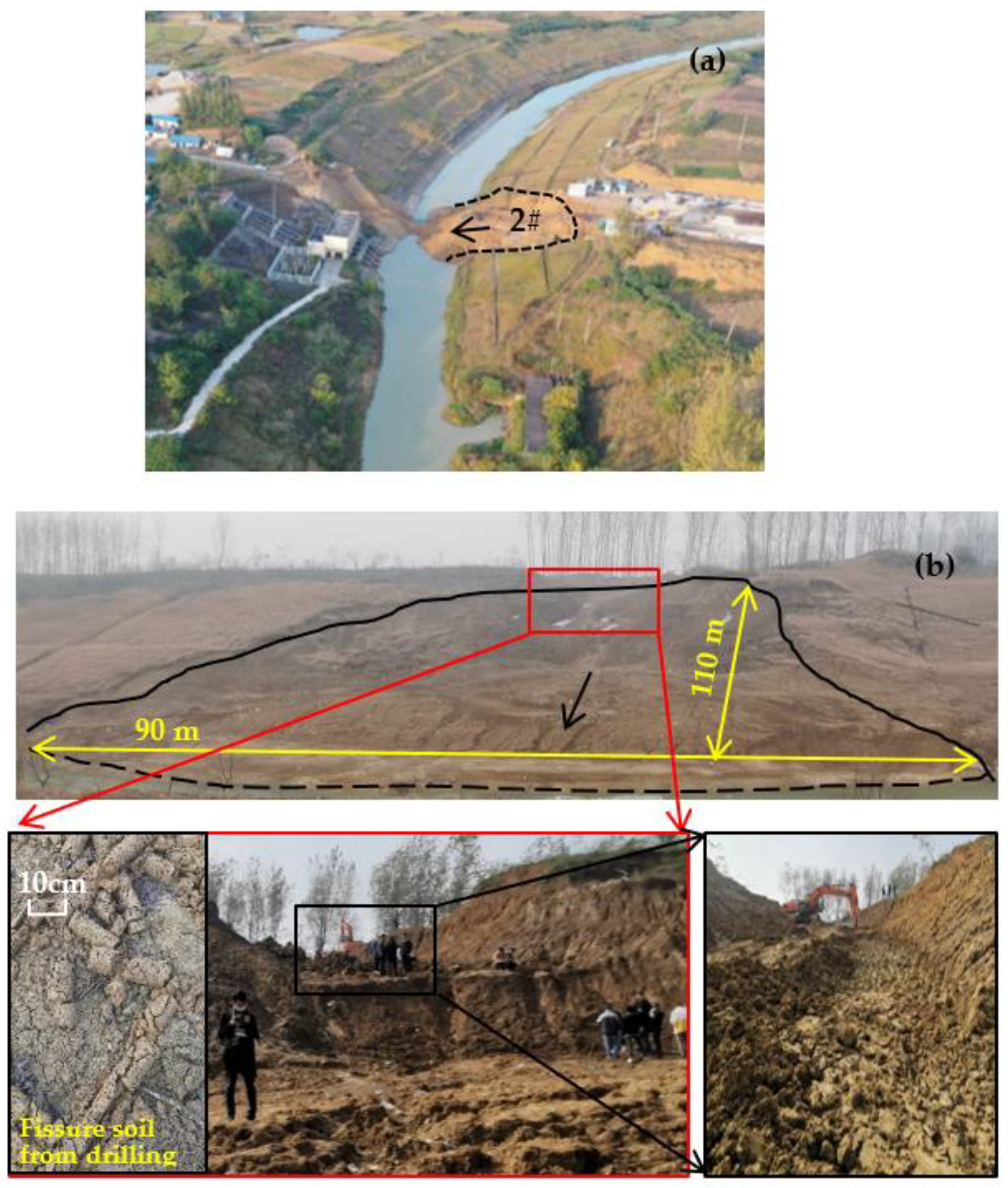
2.1. Background

The Pishihang irrigation project was built in 1958, and it is located in the middle and western part of Anhui province. It is composed of three sub-irrigated areas: the Pi river, Shi river and Hangbu river. The scope of the project covers Anhui and Henan provinces. The designed irrigated area of the project is 11.98 million mu, which is one of three super-large irrigated areas in China. The Pishihang irrigation project plays a role in urban flood control irrigation, residential water use, water conservancy and hydropower projects, aquaculture resource breeding and tourism development around water resources and water culture. In recent years, there have been many expansive soil landslides in the channel slope of the Pi river irrigation area. According to the geological survey results, the main reason for the landslides is that the seepage of the reservoir at the top of the channel slope leads to water infiltration along the cracks in the expansive soil, thus reducing the shear strength. Figure 1 shows an example of the formation of fissures on the surface of an expansive soil landslide in the Pishihang irrigation district, Anhui, China. The thickness of the landslide was approximately 2 to 5 m and the volume of the landslide was approximately 15,000 m3.

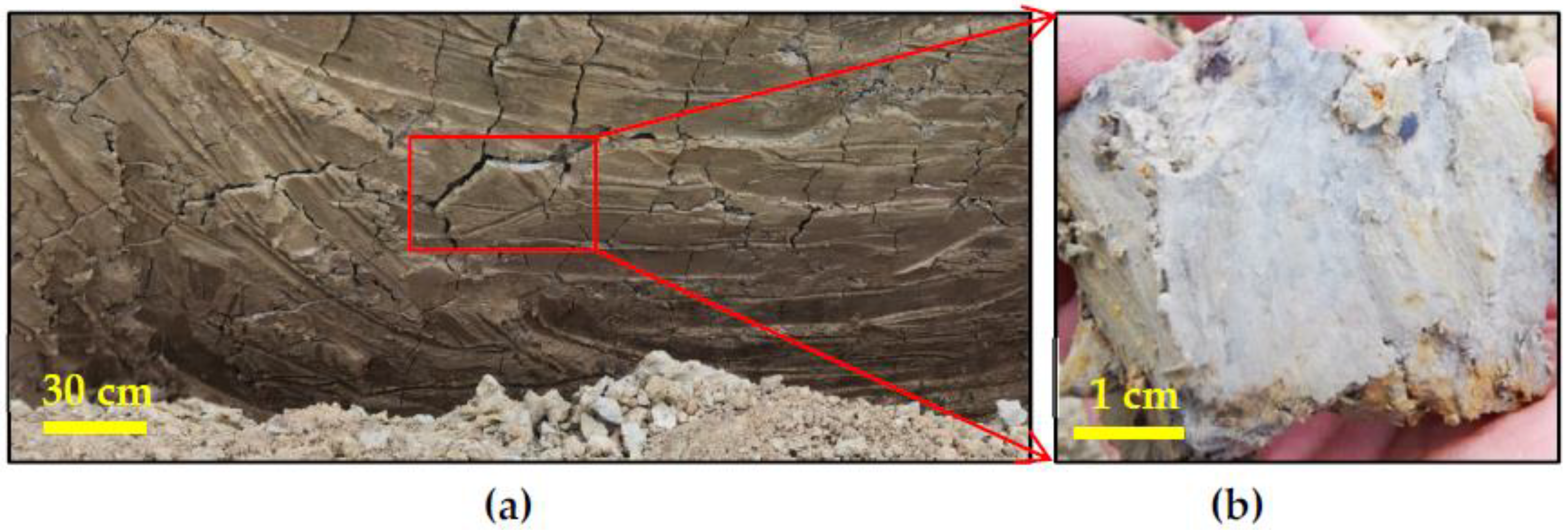
2.2. Specimen Preparation

The expansive soil was sampled from the field slope, as shown in Figure 1b crack distribution and crack interface were clearly observed in the soil (Figure 2). The samples were used to test the initial water content and dry density by using the oven-drying method and cutting-ring method, respectively. The free expansion rate, confined expansion rate and unconfined compressive strength of expansive soil samples were measured according to the standards for soil test methods in China (GB/T 50123–2019) [39]. The content of smectite was determined by clay minerals with a particle size less than 2 μm in expansive soil, according to the analysis method for clay minerals and ordinary non-clay minerals in sedimentary rocks (SY/T 5163–2018) using a TTRIII multifunctional X-ray diffractometer [40]. The physical and mechanical parameters of the specimens are given in Table 1.

3. Methodology

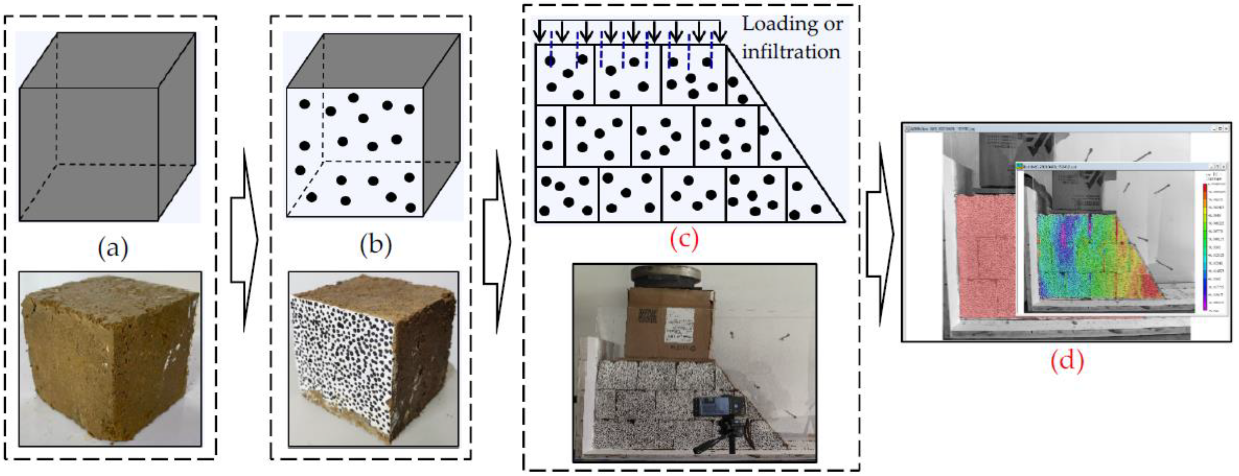
3.1. Slope Model Preparation

The expansive soil samples were prepared under a natural water content of 22.5% and dry density of 1.65 g/cm3, as shown in Figure 3a. The size of the block sample was 10 cm × 10 cm × 10 cm. One side of the block sample was painted with white acrylic paint and spotted with black (Figure 3b). The block samples were stacked together to make a fissured expansive soil slope model (Figure 3c). The model angle was set to 50–60°. Figure 4 presents six kinds of slope model, with speckles and different cracks without support. The cracks were divided into two types: single crack and crack networks. The crack angle was set to 0°, 10° and 20°. The top of the model could be loaded with 1.6, 3.2, 4.8, 6.4 or 16 MPa or irrigated at a flow rate of 25 mL/min. The weight stacking method was adopted for loading. A long piece of wood was placed on top of the model for the uniform loading of stress. Different weights were placed in the box according to the test requirements, and the box was placed on the board (Figure 3c). As the model was subjected to loading or irrigation, the cracks between the block samples produced compression or tensile deformation, and the slope produced horizontal and vertical deformation. The speckles on the surface of the block sample shifted, which could be captured on camera. Then, the VIC-2d software, which utilizes the DIC principle, was used to quantitatively obtain the horizontal and vertical deformation data of the slope model (Figure 3d).

3.2. Data Processing Method

The basic principle of data processing was to use the cross-correlation method to shoot objects in different motion states on two different images. The images were divided into square sub-regions of a certain size. The gray characteristic values of the corresponding sub-regions in the two images were compared to identify the similarity in the sub-regions and calculate the displacement of pixels, so as to obtain the local displacement field data of the images. After the analysis of the whole research area, the distribution information of the overall strain and displacement field was obtained, which was visually displayed in the form of clouds [30].
It was assumed that the gray characteristic functions of the two digital images before and after deformation were f(x, y) and g (x′, y′), where x, y and x′, y′ are the positions of a pixel point before and after deformation, respectively, and u and v represent the displacement components of the feature point along the x and y directions, as shown in Formulas (1) and (2) [24,25].
x′ = x + u + ux Δ x + uy Δ y,
y′ = y + v + vx Δ x + vy Δ y.
The correlation coefficient C in statistics was used to evaluate the degree of similarity between the two sub-regions, as shown in Formula (3).
C = f ( x , y ) · g ( x , y ) [ f 2 ( x , y ) · g 2 ( x , y ) ] 1 / 2
where f and g are gray eigenvalues of a sub-region before and after deformation, respectively. When C = 1, the two sub-regions are completely correlated. When C = 0, the two sub-regions are unrelated.
Based on the above principles, image analysis and processing could be divided into three steps: image import and image quality pre-analysis, correlation analysis and calculation and data visualization.

3.3. Test Steps

The slope model of expansive soil was created, as shown in Figure 4. Then, the top of each model was loaded with 1.6 MPa (Figure 3c). When the deformation shown by the VIC-2d software stabilized, the next level of pressure, 3.2 MPa, was applied. In the same way, the maximum pressure was increased to 16 MPa. Thus, the top of the model could be loaded with 1.6, 3.2, 4.8, 6.4 and 16 MPa in turn. The horizontal strain affected by loading was obtained using VIC-2d software (Figure 3d). A more complex condition is to consider the coupled effect of loading and infiltration on slope strain. The top of each model was loaded with 1.6 MPa and irrigated with a flow rate of 25 mL/min (Figure 3c). After the deformation stabilized, the next level of pressure of 3.2 MPa was applied and the water infiltration was continued until the next stage of deformation stabilized. Water was drained from the bottom of the slope model along the crack interfaces. In the same way, the maximum pressure increased to 16 MPa and the irrigation rate was held at 25 mL/min until the final deformation was stable. Finally, the influence of anchor reinforcement on the slope stability of fissured expansive soil was investigated. Cylindrical wood material was used to simulate anchor reinforcement. The reinforcement material provided friction and shear resistance.

4. Results and Discussion

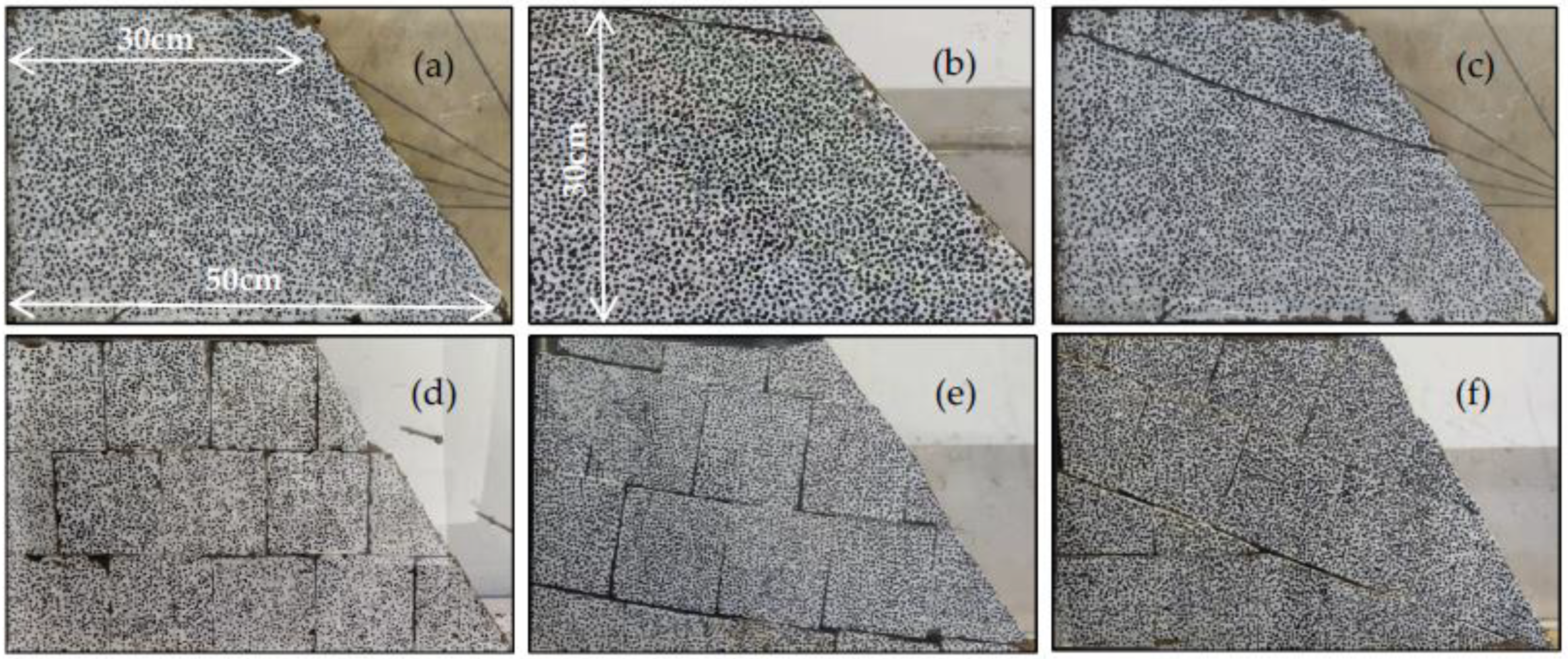
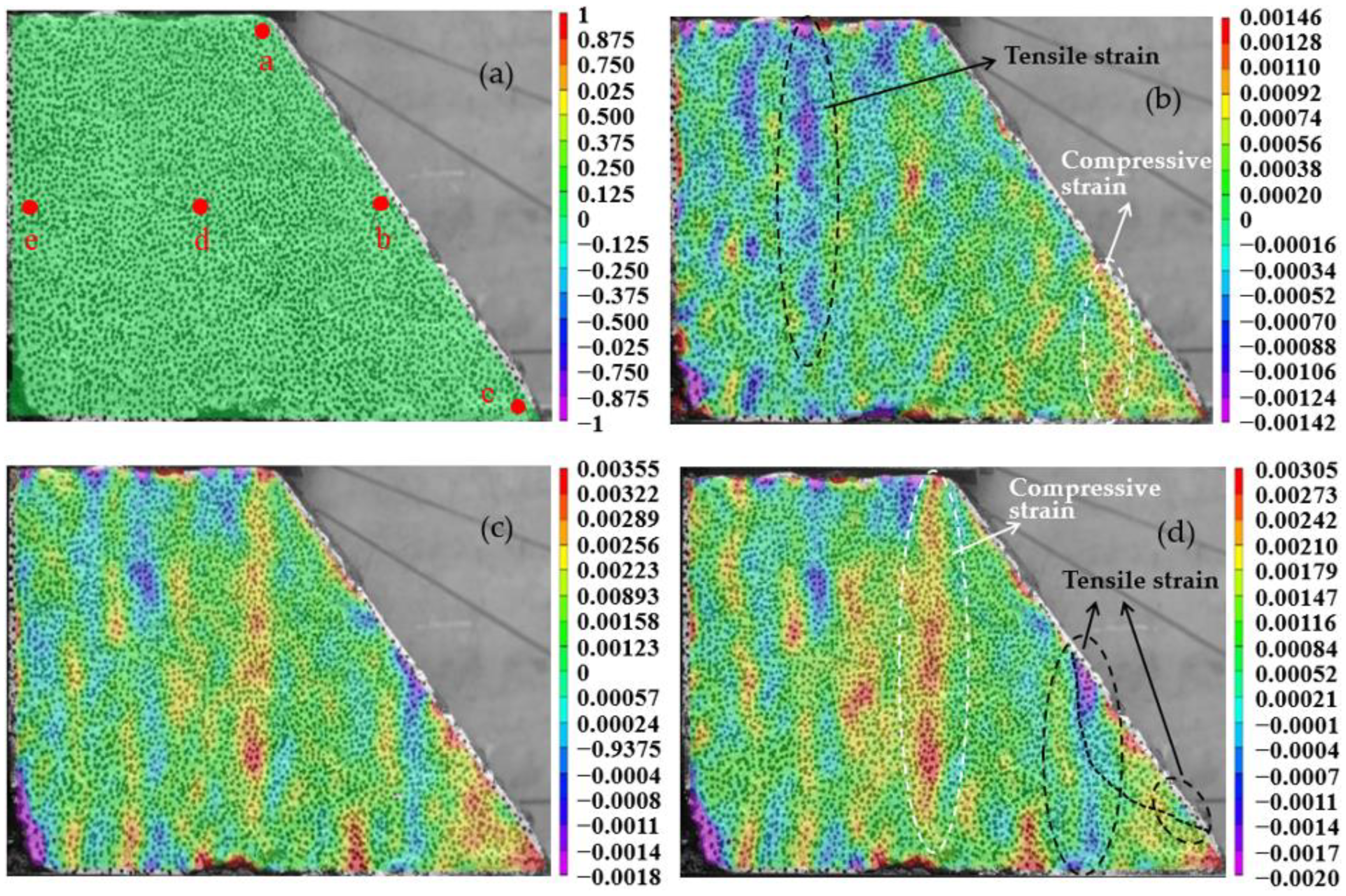
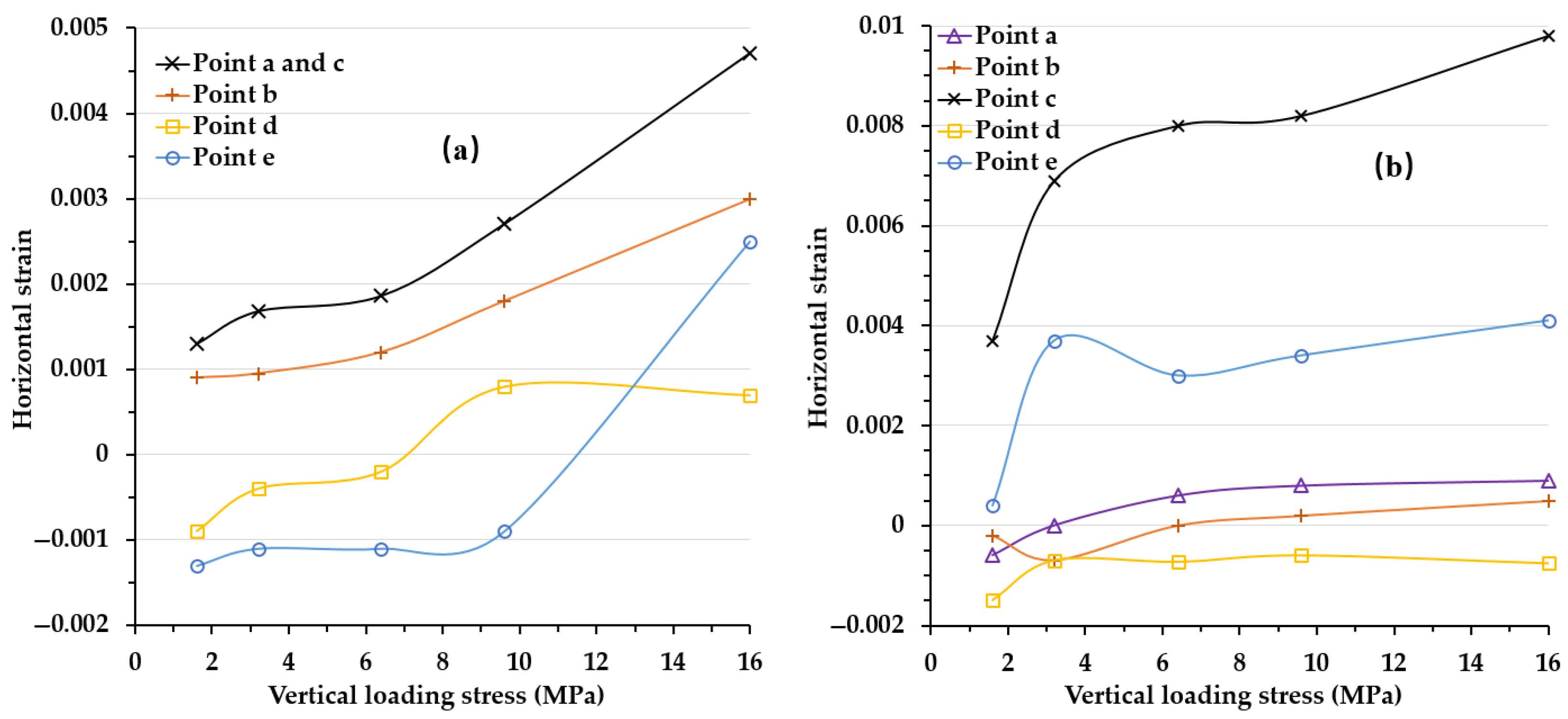
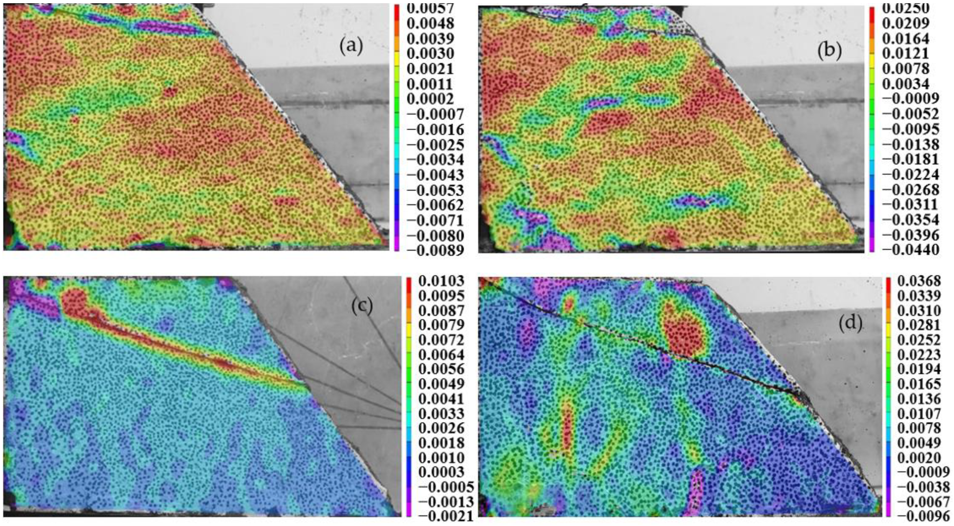
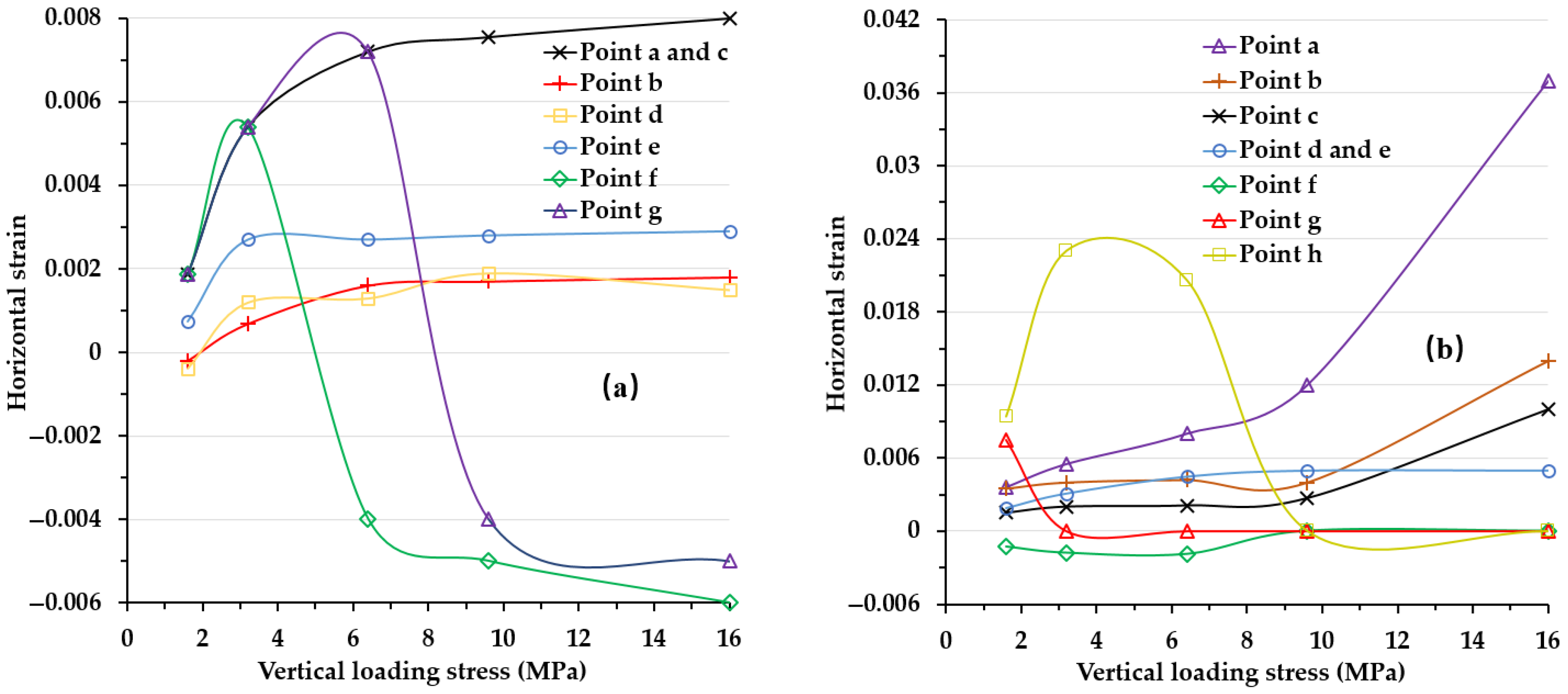
4.1. Deformation Characteristics of the Expansive Soil Slope Model with No Prefabricated Crack

The slope model of expansive soil was created with no prefabricated crack, as shown in Figure 4a. Figure 5 gives the horizontal strain contours of the slope model under different loadings, which were obtained using VIC-2d software. The horizontal strain was set to zero by default, with five strain-monitoring points from a to e (Figure 5a). During the whole loading and irrigation infiltration process, the slope soil was in a state of elastic–plastic and small deformation. Thus, the slope model did not show excessive deformation or sliding failure and no obvious surface tensile cracks appeared. With the increase in overburden loading, the horizontal strain increased gradually. Stress gradually spread from the top to the foot of the slope. There was a trend of compressive strain at the foot of the slope, and a trend of tensile strain in the middle of the slope surface. When the vertical loading increased to 16 MPa, the foot of the slope was still under pressure, the compressive stress zone appeared below the shoulder, and the tensile stress zone appeared in the lower middle of the slope (Figure 5d). Hence, the surface sliding zone began to appear. Compared with the same vertical pressure condition of 1.6 MPa, when the top of the slope was subjected to vertical loading and irrigation at the same time, the horizontal strain of the slope was obviously larger than that of the slope without infiltration (Figure 6a). With the increase in the overburden, the amount of infiltration increased gradually, and the horizontal strain of the slope continued to increase. A compressive stress zone was formed at the back of the slope, which mainly bore the overburden pressure. The surface tensile stress zone was more obvious (Figure 6b). With the increase in overburden stress and continuous infiltration, the compressive stress at point a and b on the surface of the slope decreased significantly, while that at point c at the foot of the slope increased significantly (Figure 7). Based on the strain development law and strain statistics, the concentrated area of tension strain could be easily identified (Figure 5d and Figure 6b). A sliding surface was gradually formed (Figure 6b). Therefore, for an expansive soil slope without prefabricated cracks, there was no fixed sliding surface under loading conditions. When the slope was subjected to excessive overburden pressure, the potential sliding surface was gradually formed (Figure 5d). More importantly, it can be seen that water infiltration had a great influence on the stability of the slope surface and made the sliding surface more shallow (Figure 6b).

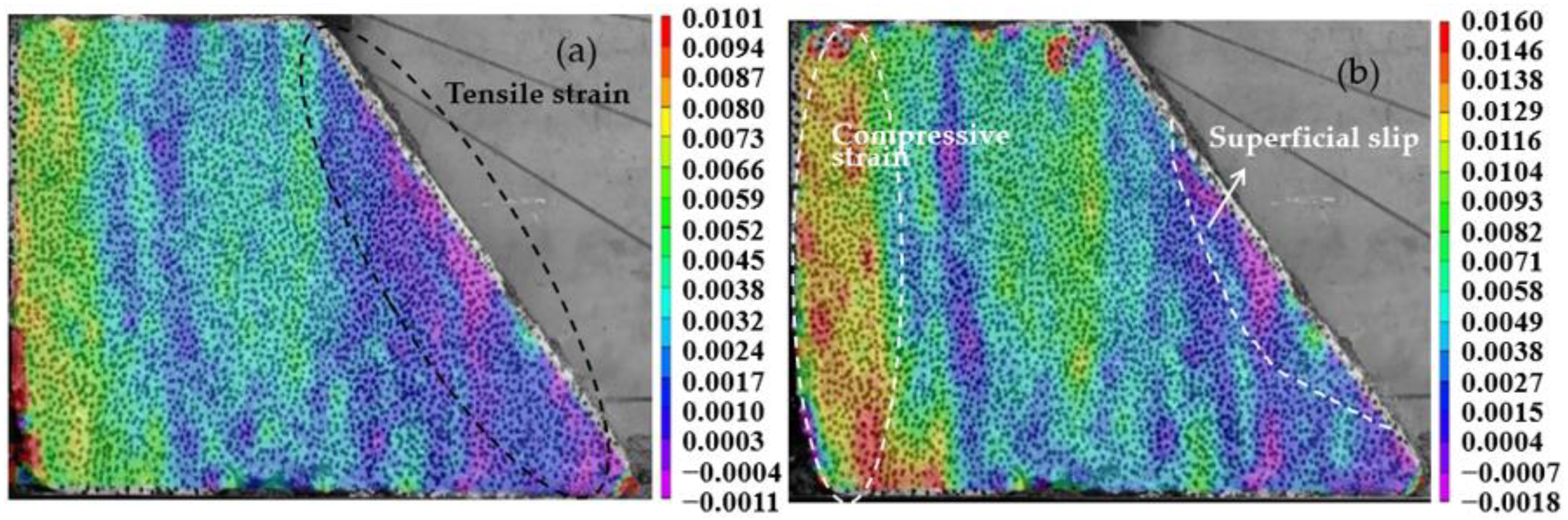
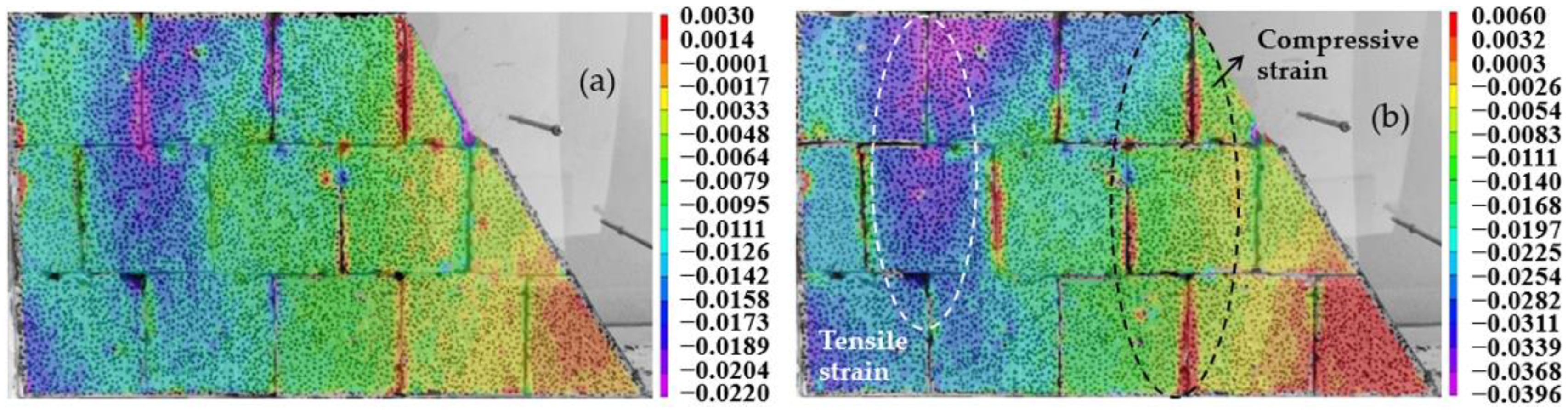
4.2. Deformation Characteristics of the Expansive Soil Slope Model with One Crack

The slope model of expansive soil with one crack was created, as shown in Figure 4b,c. Figure 8 shows the horizontal strain contours of the slope model under different loadings, which were obtained using VIC-2d software. There were eight strain monitoring points from a to h, as shown in Figure 8a. Figure 9 presents the horizontal strain contours of the slope under loading and irrigation. With the increase in overburden loading, the horizontal strain increased gradually. There was a trend of tensile strain at the foot of the slope, and a trend of compressive strain above the crack (Figure 8b). The crack played a role in stress segmentation and strain discontinuity. With the increase in crack angle, stress was transferred to the crack interface, resulting in stress concentration (Figure 8c). The upper part of the crack presented a tensile strain state, and the lower part presented a compressive strain state. Thus, the shear slip plane was easily formed along the crack plane (Figure 8d). The infiltration of water caused tensile strain at the crack of point f (Figure 8a and Figure 9a). The crack interface gradually closed at point h and g with the continuous infiltration. Under the action of water lubrication, the discontinuous interface became nearly continuous. Thus, the overburden pressure was transmitted from the top of the slope to the middle and foot of the slope. However, as the overburden pressure and infiltration continued to increase, the crack interface presented a large deformation and breakage state due to the excessive tensile strain (Figure 9d). Excessive overlying stress revives the existing crack and produces sliding along the crack interface; because of the opening of the crack, it was difficult to transfer stress from the top to the bottom of the slope. With the increase in overburden pressure and irrigation, the crack interface showed more and more tensile strain (Figure 10). Therefore, under the combined action of overburden pressure and irrigation, the crack hindered the transfer of pressure to the part under the crack due to the activation of the crack, and the large angle crack of the slope was prone to slope sliding (Figure 9d).

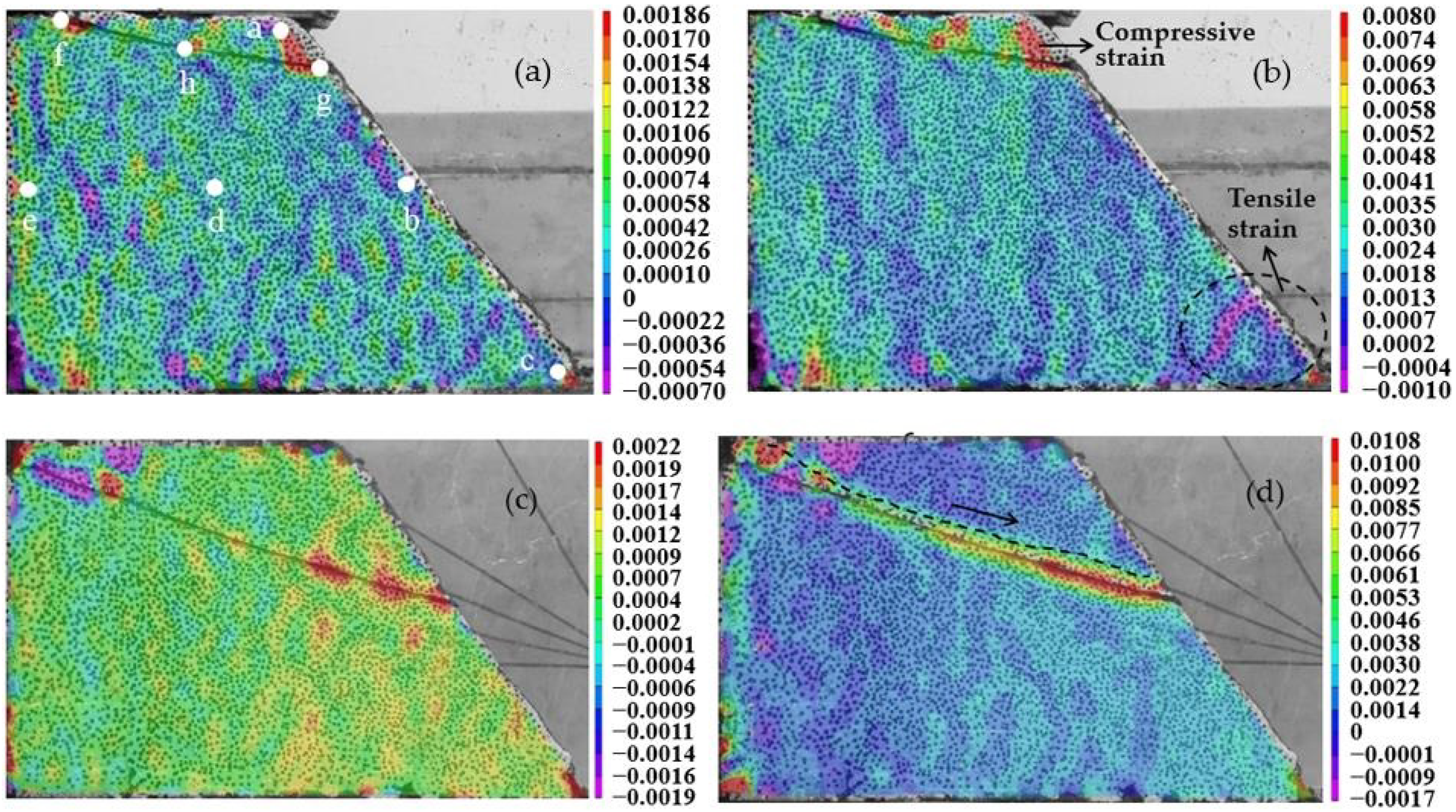
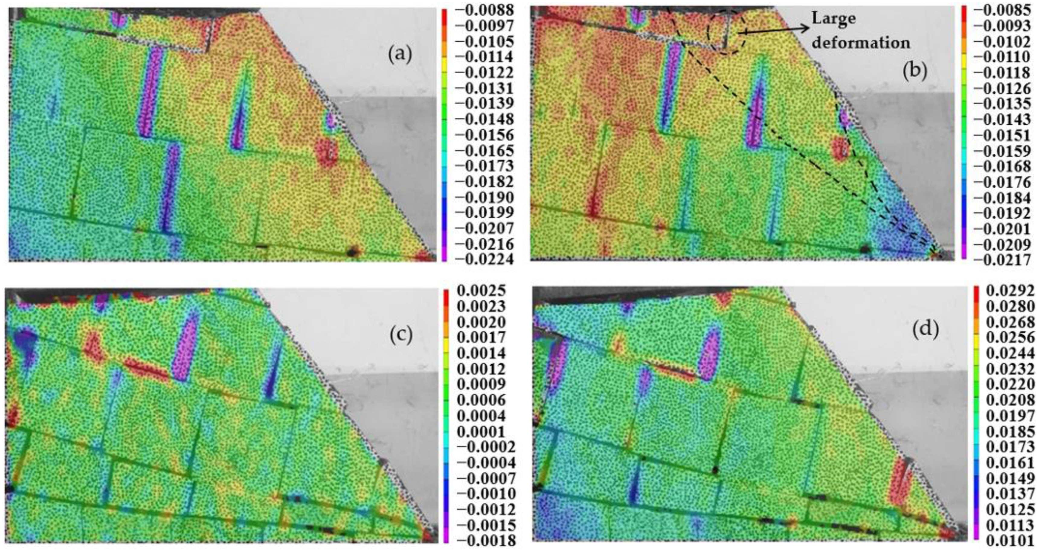
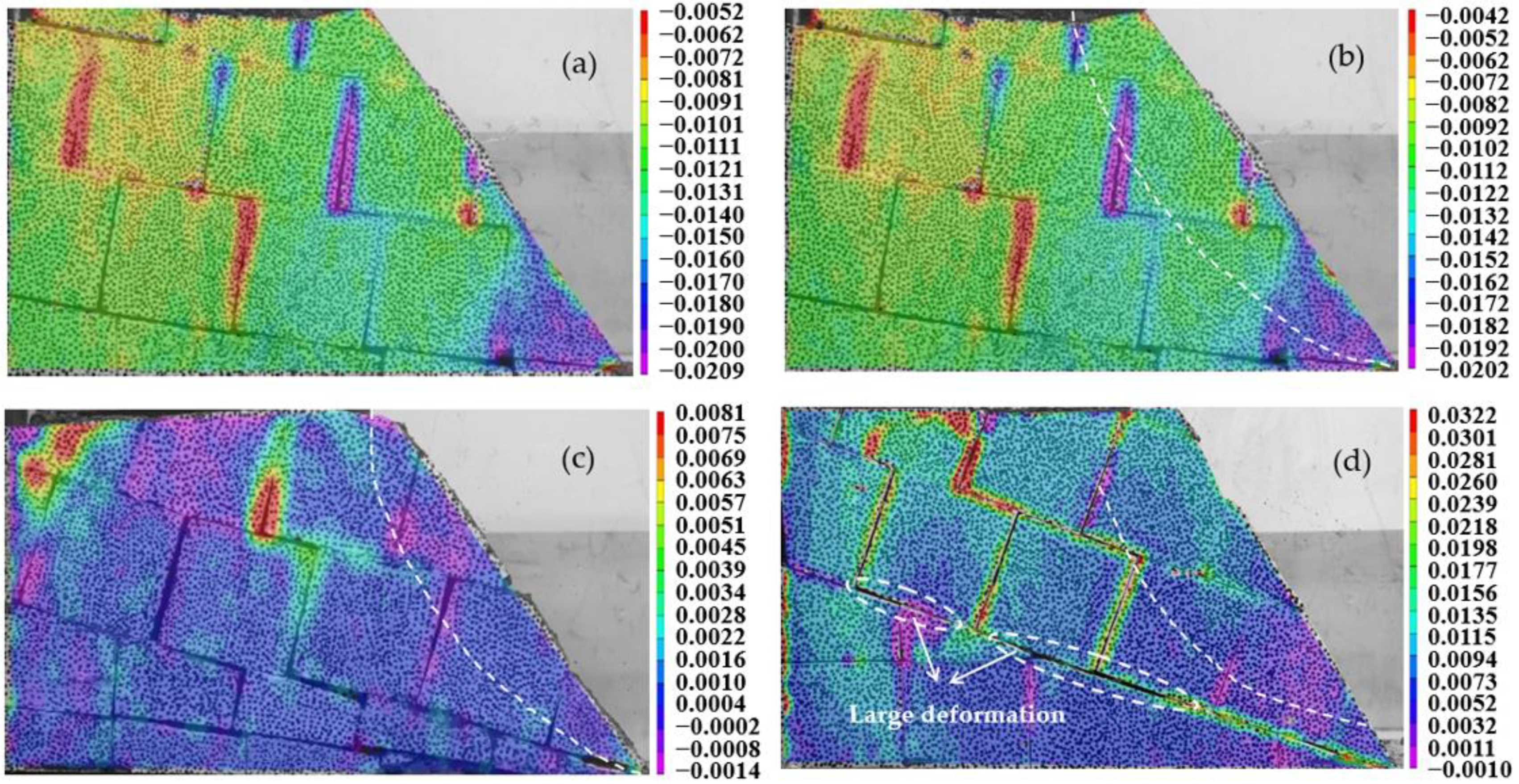
4.3. Deformation Characteristics of the Expansive Soil Slope Model with Crack Networks

A slope model of expansive soil with crack networks was created, as shown in Figure 4d–f. Figure 11 shows the strain contours of the slope model with horizontal crack networks under different loadings. With the increase in overburden loading, the horizontal strain increased gradually. Stress gradually spread from the top to the foot of the slope. Tensile strain was formed at the back edge of the slope, and compressive strain was formed at the front edge and foot of the slope. The rule of the strain distribution area was similar to that in Figure 5b,d. Stress concentration was common at the frontal cracks. Figure 12 shows the horizontal strain contours of the slope model with crack networks at an angle of 10° and 20° under different loadings. For the slope with small-angle crack networks, the tensile strain tended to appear at the crack with the increase in overburden pressure. The surface of the slope formed a transfixion tensile state, and the value of the partial tensile strain was too large to show due to the limitations of the software’s functions. For the slope with a large-angle crack, with the increase in overburden pressure or gravity weight stress, the crack gradually closed, and the slope as a whole presented the compressive strain state and tended to be stable (Figure 12d). Figure 13 shows the horizontal strain contours of the slope model with crack networks at angles of 10° and 20° under different loadings and irrigation with a flow rate of 25 mL/min. Under the combined action of overburden pressure and irrigation, the tensile strain crack zone gradually moved to the surface of the slope, forming the shallow tensile strain zone (Figure 13b), which is compared with the strain law under overburden loading only in Figure 12a,b. The infiltration of water caused the slope with crack networks to show a large deformation at the superficial crack (Figure 13d). Thus, the appearance of crack networks in expansive soil caused the slope to slide towards the shallow surface, and the water infiltration caused the tensile state of the cracks to be more obvious, which promoted the shallow slide.

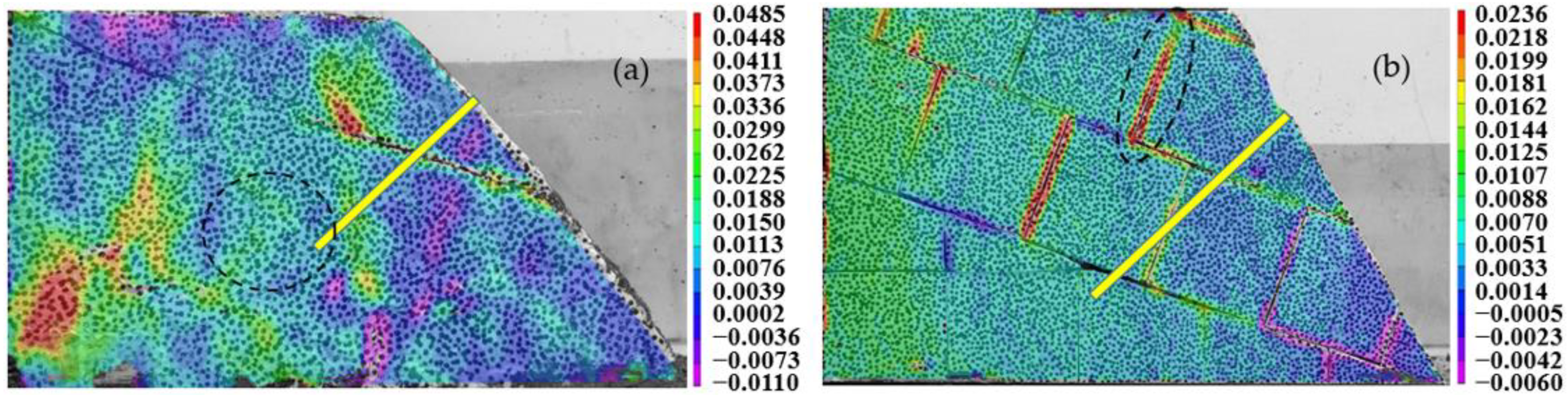
4.4. Deformation Characteristics of the Expansive Soil Slope Model after Reinforcement

Figure 14 presents the horizontal strain contours of the slope model strengthened with an anchor stock under a loading of 16 MPa and irrigation at a flow rate of 25 mL/min. Figure 15 shows the representative strain values of the slope model under loading and irrigation. Before the reinforcement, the crack interface presented a large deformation state due to the excessive tensile strain. After reinforcement, the tensile strain near the crack interface became obviously smaller, and even changed from tensile strain to compressive strain (Figure 15a,b). The strain state in the deep part of the slope changed from tensile strain to compressive strain, indicating that the crack interface can effectively transfer the load from the top of the slope. Thus, the central reinforcement can effectively improve the stress environment in the middle of the slope and improve the stability of the slope (Figure 15a,b). For the crack networks model before reinforcement, the cracks near the top of the slope showed tensile strain due to the pressure on the top of the slope. After reinforcement, the anchor effectively supported the pressure on the top of the slope. Therefore, the tensile strain of the cracks at the top of the slope changed to compressive strain (Figure 14b and Figure 15c,d). The reinforcement of the anchor caused the reinforced area of the fissure slope to become whole. As a result, the compressive stress zone at the foot of the fissure slope was transformed into a tensile stress zone due to the cutting action of the cracks and the stress transfer at the top of the slope. This was similar to the strain state of the slope without prefabricated cracks (Figure 5). Thus, it was very important to reinforce the cracks at the foot of the slope. In general, the key to the reinforcement of the fissured expansive soil slope is to strengthen the crack interface in the state of tensile strain, and to close it in a state of compression. The middle and foot of the fissured expansive soil slope are the key areas for reinforcement.

5. Conclusions

This study focused on the relationship between slope state and crack development in fissured expansive soils and used a series of physical model tests to consider different types of cracks, different overburden loadings and irrigation. The main conclusions are as follows:
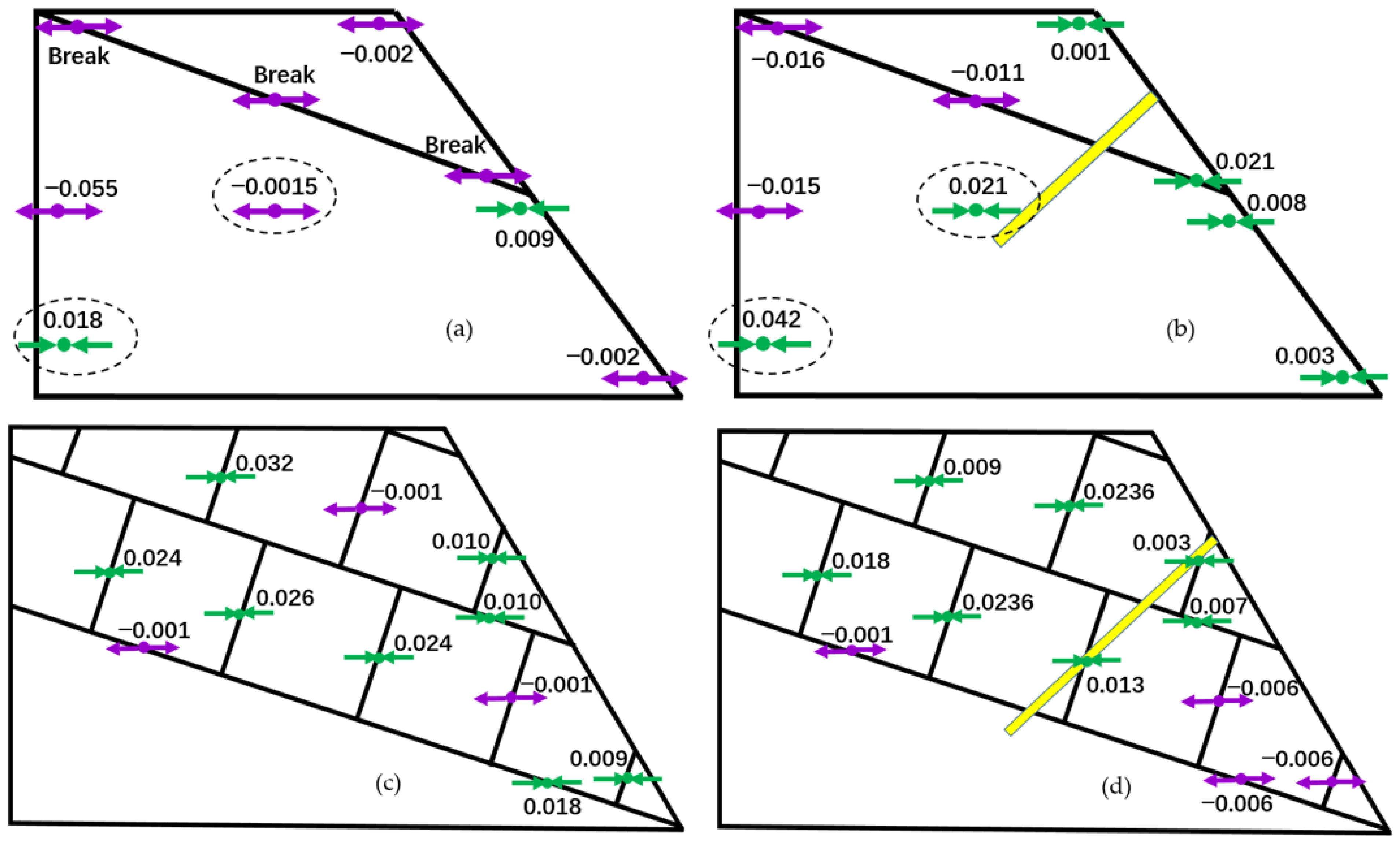
  • Overburden pressure or gravity stress results in tensile strain in the middle and compressive strain at the foot of the expansive soil slope without prefabricated cracks. Water infiltration promotes the extension of tensile strain on the surface of the slope.
  • Excessive overlying stress revives the existing cracks and produces sliding along the crack interface of an expansive soil slope with one crack. Additionally, water infiltration promotes the formation of a shallow sliding surface.
  • The sliding surface commonly appears where crack networks exist in the shallow of an expansive soil slope. Water infiltration promotes the extension of tensile strain on the surface of the slope with crack networks, which intensifies the formation of surface- or shallow-layer sliding surfaces.
  • The middle and foot of the fissured expansive soil slope are the key positions for reinforcement, which were revealed by the mutual transformation of tensile strain and compressive strain on the surface of the slope.
  • The controlling effects of cracks on strain continuity, stress transfer and the stability of the expansive soil slope were revealed from the perspective of slope strain development under different loadings and irrigation.
  • Water infiltration has a great influence on the stability of the slope surface; more importantly, it causes the sliding surface of the fissured expansive soil slope to be shallower.
  • Because the water used in the test was plain water, there was no color mark, so the flow of water could not be seen in the seepage process. In future studies, colored water or tracers could be used for seepage tests to track fluid flow through cracks.
  • The quantitative study of the effect of cracks on slope stability should be the focus of future work.

Author Contributions

Conceptualization, Z.L.; Data curation, Z.L. and Y.K.; Formal analysis, Z.L. and L.F.; Investigation, Z.L., Y.Z. and Z.Q.; Methodology, Z.L. and R.H.; Project administration, Z.L.; Validation, Z.L.; Writing—original draft, Z.L.; Writing—review and editing, Z.L. All authors have read and agreed to the published version of the manuscript.

Funding

This work was funded by the National Key Research and Development Plan of China (Grant No. 2019YFC1509903), the Second Tibetan Plateau Scientific Expedition and Research Program (STEP) (Grant No. 2019QZKK0904), National Natural Science Foundation of China (Grant No. 42177146, 41790442), Key Research and Development Plan of Yunnan Province (Grant No. 202103AA080013), Chinese Academy of Sciences Key Deployment Project (Grant No. KFZD-SW-422), Youth Innovation Promotion Association CAS (Grant No. 2017092) and the International Cooperation Program of Chinese Academy of Sciences (Grant No. 131551KYSB20180042).

Institutional Review Board Statement

Not applicable.

Informed Consent Statement

Not applicable.

Conflicts of Interest

The authors declare no conflict of interest.

References

  1. Khazaei, J.; Moayedi, H. Soft expansive soil improvement by eco-friendly waste and quick lime. Arab. J. Sci. Eng. 2019, 44, 8337–8346. [Google Scholar] [CrossRef]
  2. Krohn, J.P.; Slosson, J.E. Assessment of expansive soils in the United States. In Proceedings of the 4th International Conference on Expansive Soils, Denver, CO, USA, 16–18 June 1980; pp. 596–608. [Google Scholar]
  3. Shi, B.; Jiang, H.; Liu, Z.; Fang, H. Engineering geological characteristics of expansive soils in China. Eng. Geol. 2002, 67, 63–71. [Google Scholar] [CrossRef]
  4. Steinberg, M. Geomembranes and the Control of Expansive Soils in Construction; McGraw-Hill: New York, NY, USA, 1998. [Google Scholar]
  5. Tiwari, N.; Satyam, N. Coupling effect of pond ash and polypropylene fiber on strength and durability of expansive soil subgrades: An integrated experimental and machine learning approach. J. Rock Mech. Geotech. Eng. 2021, 13, 1101–1112. [Google Scholar] [CrossRef]
  6. Pei, P.; Zhao, Y.L.; Ni, P.P.; Mei, G.X. A protective measure for expansive soil slopes based on moisture content control. Eng. Geol. 2020, 269, 105527. [Google Scholar] [CrossRef]
  7. Ng, C.W.W.; Zhan, L.T.; Bao, C.G.; Fredlund, D.G.; Gong, B.W. Performance of an unsaturated expansive soil slope subjected to artificial rainfall infiltration. Geotechnique 2003, 53, 143–157. [Google Scholar] [CrossRef]
  8. Azam, S.; Wilson, G.W. Volume change behavior of a fissured expansive clay containing anhydrous calcium sulfate. In Proceedings of the 4th International Conference on Unsaturated Soils, Carefree, AZ, USA, 2–6 April 2006; Volume 1, pp. 906–915. [Google Scholar]
  9. Krisnanto, S.; Rahardjo, H.; Fredlund, D.; Leong, E. Water content of soil matrix during lateral water flow through cracked soil. Eng. Geol. 2016, 210, 168–179. [Google Scholar] [CrossRef]
  10. Xie, C.R.; Ni, P.P.; Xu, M.J.; Mei, G.X.; Zhao, Y.L. Combined measure of geometry optimization and vegetation for expansive soil slopes. Comput. Geotech. 2020, 7, 103588. [Google Scholar] [CrossRef]
  11. Li, J.H.; Zhang, L.M. Study of desiccation crack initiation and development at ground surface. Eng. Geol. 2011, 123, 347–358. [Google Scholar] [CrossRef]
  12. Qi, W.; Zhang, Z.Y.; Wang, C.; Chen, Y.; Zhang, Z.M. Crack closure and flow regimes in cracked clay loam subjected to different irrigation methods. Geoderma 2020, 358, 113978. [Google Scholar] [CrossRef]
  13. Xu, J.; Ren, J.; Wang, Z.; Wang, S.; Yuan, J. Strength behaviors and meso-structural characters of loess after freeze-thaw. Cold Reg. Sci. Technol. 2018, 148, 104–120. [Google Scholar] [CrossRef]
  14. Ding, L.Q.; Vanapalli, S.K.; Zou, W.L.; Han, Z.; Wang, X.Q. Freeze-thaw and wetting-drying effects on the hydromechanical behavior of a stabilized expansive soil. Constr. Build. Mater. 2021, 275, 122162. [Google Scholar] [CrossRef]
  15. Lu, Y.; Liu, S.; Alonso, E.; Wang, L.; Xu, L.; Li, Z. Volume changes and mechanical degradation of a compacted expansive soil under freeze-thaw cycles. Cold Reg. Sci. Technol. 2019, 157, 206–214. [Google Scholar] [CrossRef]
  16. Chen, L.; Yin, Z.Z.; Zhang, P. Relationship of resistivity with water content and fissures of unsaturated expansive soils. J. China Univ. Min. Technol. 2007, 17, 537–540. (In Chinese) [Google Scholar] [CrossRef]
  17. Hou, T.S.; Xu, G.L.; Shen, Y.J.; Wu, Z.Z.; Zhang, N.N.; Wang, R. Formation mechanism and stability analysis of the Houba expansive soil landslide. Eng. Geol. 2013, 161, 34–43. [Google Scholar] [CrossRef]
  18. Cho, S.E.; Lee, S.R. Instability of unsaturated soil slopes due to infiltration. Comput. Geotech. 2001, 28, 185–208. [Google Scholar] [CrossRef]
  19. Cai, F.; Ugai, K. Numerical analysis of rainfall effects on slope stability. Int. J. Geomech. 2004, 4, 69–78. [Google Scholar] [CrossRef]
  20. Qi, S.; Vanapalli, S.K. Influence of swelling behavior on the stability of an infinite unsaturated expansive soil slope. Comput. Geotech. 2016, 76, 154–169. [Google Scholar] [CrossRef]
  21. Qi, S.; Vanapalli, S.K. Simulating Hydraulic and Mechanical responses of Unsaturated Expansive Soil Slope to Rainfall: Case Study. Int. J. Geomech. 2018, 18, 05018002. [Google Scholar] [CrossRef]
  22. Schnellmann, R.; Busslinger, M.; Schneider, H.R.; Rahardjo, H. Effect of rising water table in an unsaturated slope. Eng. Geol. 2010, 114, 71–83. [Google Scholar] [CrossRef]
  23. Take, W.A.; Bolton, M.D.; Wong, P.C.P.; Yeung, F.J. Evaluation of landslide triggering mechanisms in model fill slopes. Landslides 2004, 1, 173–184. [Google Scholar] [CrossRef]
  24. Yamaguchi, I. A laser-speckle strain gauge. J. Phys. E Sci. Instrum. 1981, 14, 1270–1273. [Google Scholar] [CrossRef]
  25. Ranson, W.F.; Peters, W.H. Digital image techniques in experimental stress analysis. Opt. Eng. 1982, 21, 427–431. [Google Scholar]
  26. Kahn, J.Z.L.; Chu, T.C. Three-dimensional displacement measurement using digital image correlation and photogrammic analysis. Exp. Mech. 1990, 30, 10–16. [Google Scholar] [CrossRef]
  27. Li, Y.H.; Jing, H.W.; Zhu, H.H.; Ma, X.F. Experimental investigation on progressive deformation patterns of sand foundation in centrifuge test using digital photogrammetry. Chin. J. Geotech. Eng. 2006, 28, 306–311. (In Chinese) [Google Scholar]
  28. Zhao, C.; Bao, C.; Song, T.H.; Zhao, C.F.; Tian, J.S. Application of digital image correlation method in experimental research on crack propagation of brittle rock. Chin. J. Geotech. Eng. 2015, 37, 944–951. (In Chinese) [Google Scholar]
  29. Teng, Y.; Stanier, S.; Gourvenec, S.M. Synchronised multi-scale image analysis of soil deformations. Int. J. Phys. Model. Geotech. 2017, 17, 53–71. [Google Scholar] [CrossRef] [Green Version]
  30. Lin, L.; Tang, C.S.; Cheng, Q.; Zeng, H.; Shi, B. Desiccation cracking bebavior of soils based on digital image correlation technique. Chin. J. Geotech. Eng. 2019, 41, 1311–1318. (In Chinese) [Google Scholar]
  31. Solanki, P.; Khoury, N.; Zaman, M.M. Engineering properties and moisture susceptibility of silty clay stabilized with lime, class C fly ash, and cement kiln dust. J. Mater. Civ. Eng. 2009, 21, 749–757. [Google Scholar] [CrossRef]
  32. Syed, M.; Ray, A.G. Effect of natural fiber reinforcement on strength response of alkali activated binder treated expansive soil: Experimental investigation and reliability analysis. Constr. Build. Mater. 2021, 273, 121743. [Google Scholar] [CrossRef]
  33. Rahardjo, H.; Santoso, V.A.; Leong, E.C.; Ng, Y.S.; Tam, C.; Satyanaga, A. Use of recycled crushed concrete and secudrain in capillary barriers for slope stabilization. Can. Geotech. J. 2013, 50, 662–673. [Google Scholar] [CrossRef]
  34. Harnas, F.; Rahardjo, H.; Leong, E.; Wang, J. Physical model for the investigation of capillary-barrier performance made using recycled asphalt. Geotech. Test. J. 2016, 39, 977–990. [Google Scholar] [CrossRef]
  35. Narani, S.S.; Abbaspour, M.; Mohammad Hosseini, S.M.M.; Aflaki, E.; Moghadas Nejad, F. Sustainable reuse of Waste Tire Textile Fibers (WTTFs) as reinforcement materials for expansive soils: With a special focus on landfill liners/covers. J. Clean. Prod. 2020, 247, 119151. [Google Scholar] [CrossRef]
  36. Rahardjo, H.; Satyanaga, A.; Leong, E.C.; Noh, O. Performance of residual soil as cover system for a sanitary landfill in Singapore. J. Perform. Constr. Facil. 2017, 31, D4016004. [Google Scholar] [CrossRef]
  37. Liu, S.; Bai, F.; Wang, Y.; Wang, S.; Li, Z. Treatment for expansive soil channel slope with soilbags. J. Aerosp. Eng. 2013, 26, 657–666. [Google Scholar] [CrossRef] [Green Version]
  38. Xu, Y.F.; Zhang, H.R. Design of soilbag-protected slopes in expansive soils. Geotext. Geomembr. 2021, 49, 1036–1045. [Google Scholar] [CrossRef]
  39. GB/T 50123–2019. Standard for Soil Test Method; China Planning Press: Beijing, China, 2019. (In Chinese)
  40. SY/T 5163–2018. Analysis Method for Clay Minerals and Ordinary Non-Clay Minerals in Sedimentary Rocks by the X-ray Diffraction; National Energy Administration: Beijing, China, 2018. (In Chinese)
Figure 1. An expansive soil landslide in the Pishihang irrigation district, Anhui, China. (a) The 2# landslide happened in late 2019; (b) sampling on the landslide.
Applsci 11 10891 g001
Figure 2. The expansive soil specimen in the field. (a) Crack distribution; (b) crack interface.
Applsci 11 10891 g002
Figure 3. Model tests of expansive soil with different crack networks. (a) Remolded sample of expansive soil; (b) remolded sample with speckles; (c) expansive soil slope model with cracks; (d) strain images from VIC-2d software.
Applsci 11 10891 g003
Figure 4. Slope model of expansive soil with different cracks without support. (a) No prefabricated crack; (b) one crack with an inclination of 10°; (c) one crack with an inclination of 20°; (d) horizontal crack networks; (e) crack networks with an inclination of 10°; (f) crack networks with an inclination of 20°.
Applsci 11 10891 g004
Figure 5. Strain contours of the slope model with no crack under different loadings. (a) No loading; (b) under 1.6 MPa; (c) under 3.2 MPa; (d) under 16 MPa.
Applsci 11 10891 g005
Figure 6. Strain contours of the slope model under different loadings and irrigation with 25 mL/min. (a) Under 1.6 MPa; (b) under 16 MPa.
Applsci 11 10891 g006
Figure 7. Horizontal strain value of the slope model with no crack. (a) Under different loading; (b) under different loadings and irrigation with 25 mL/min.
Applsci 11 10891 g007
Figure 8. Strain contours of the slope model with one crack at an angle of 10° and 20° under different loadings. (a) Under 1.6 MPa at 10°; (b) under 16 MPa at 10°; (c) under 1.6 MPa at 20°; (d) under 16 MPa at 20°.
Applsci 11 10891 g008
Figure 9. Strain contours of the slope model with one crack under different loadings and irrigation with a flow rate of 25 mL/min. (a) Under 1.6 MPa at 10°; (b) under 16 MPa at 10°; (c) under 1.6 MPa at 20°; (d) under 16 MPa at 20°.
Applsci 11 10891 g009
Figure 10. Horizontal strain value of the slope model with one crack at 10°. (a) Under different loadings; (b) under different loadings and irrigation with 25 mL/min.
Applsci 11 10891 g010
Figure 11. Strain contours of the slope model with horizontal crack networks under different loadings. (a) Under 1.6 MPa; (b) under 16 MPa.
Applsci 11 10891 g011
Figure 12. Strain contours of the slope model with crack networks at an angle of 10° and 20° under different loadings. (a) Under 1.6 MPa at 10°; (b) under 16 MPa at 10°; (c) under 1.6 MPa at 20°; (d) under 16 MPa at 20°.
Applsci 11 10891 g012
Figure 13. Strain contours of the slope model with crack networks under different loadings and irrigation with a flow rate of 25 mL/min. (a) Under 1.6 MPa at 10°; (b) under 16 MPa at 10°; (c) under 1.6 MPa at 20°; (d) under 16 MPa at 20°.
Applsci 11 10891 g013
Figure 14. Strain contours of the slope model after reinforcement under loading and irrigation. (a) One crack at 20°; (b) crack networks at 20°.
Applsci 11 10891 g014
Figure 15. Strain values of the slope model after reinforcement under loading and irrigation. (a) One crack at 20°; (b) one crack at 20° strengthened with an anchor stock; (c) crack networks at 20°; (d) crack networks at 20° strengthened with an anchor stock.
Applsci 11 10891 g015
Table 1. The physical and mechanical parameters of expansive soils.
Water Content (%)Dry Density (g/cm3)Free Expansion Rate (%)Confined Expansion Rate (%)Unconfined Compressive Strength (kPa)Smectite Content
(%)
21.0~23.01.55~1.7540~653.0~6.0180~21016.5~19.6
Publisher’s Note: MDPI stays neutral with regard to jurisdictional claims in published maps and institutional affiliations.

