Article

Experimental Investigation of the Fatigue Lifespan of Anchor Bolts with Consideration of Loading History

1
Department of Applied Mechanics and Mechanical Engineering, Faculty of Mechanical Engineering, Technical University of Košice, Letná 9, 042 00 Košice, Slovakia
2
Department of Applied Mechanics, Faculty of Mechanical Engineering, University of Žilina, Univerzitná 8215/1, 010 26 Žilina, Slovakia
3
Department of Automation and Human Machine Interactions, Faculty of Mechanical Engineering, Technical University of Košice, 042 00 Košice, Slovakia
*
Author to whom correspondence should be addressed.
Appl. Sci. 2021, 11(23), 11399; https://doi.org/10.3390/app112311399
Submission received: 16 November 2021 / Revised: 26 November 2021 / Accepted: 28 November 2021 / Published: 2 December 2021
(This article belongs to the Special Issue Advanced Engine Technologies and Innovative Vehicle Driving Systems)

Abstract

:
Preloaded bolted connections are one of the most used approaches for anchoring steel structures and equipment. Preload is induced by a mechanical tightening of the nut with the required torque. In the case of anchor bolts embedded in a concrete base, the prescribed tightening procedure has to be followed for safe and reliable operation. The present paper addresses the problem of anchoring a new casting pedestal using the original anchor bolts. The aim was to verify the original anchoring system’s reliable and safe operation, taking into account the current condition of the bolts. The analysed anchoring bolts are subjected to cyclic (disappearing) stress during the rotation of the casting pedestal. If the interplays between the anchor bolt and the concrete foundation were damaged, production would shut down, resulting in high economic losses. For this reason, the authors used a modified nut with a lightened first thread when investigating the actual state of the anchoring and setting the required preload. The shape and dimensions of the nut were determined based on the results of numerical modelling. The experimental measurements consisted of two phases. In the first phase, the values of axial forces in the anchor bolts at the required preload were set using the designed dynamometers. The second phase was focused on the operational measurements. The methodology of measuring the axial forces and the interpretation of the results obtained, including a comprehensive view of the anchoring safety, provides relevant evidence of the functionality and effectiveness of the proposed solution. Based on the results of the operational measurement and the prescribed handling of the casting pedestal, the lifespan of the anchoring was determined to be 3650 days under the loading cycles to date.

1. Introduction

The anchoring between a metallic component and a concrete foundation is an essential point in the stability and durability of the structure. This joint has to transfer the self-weight of the structure and tensile, compressive, and shearing loads created by the structure in operation. Numerous standards [1,2,3] deal with the design and connection of bolts (anchor bolts) with concrete. In recent years, anchor bolt failures have been studied extensively in many ways, including experimental testing, numerical simulations, and verifications. Delhomme et al. [4] studied the experimental behaviour of anchor bolts under static tensile loading and also analysed the relaxation of these bolts. Li and Liu [5] studied the shear behaviour of the fully grounded bolts through experimental testing, during which the direct shear tests were carried out on three groups of specimens with different bolting angles or grout strengths, measuring shear loads, shear displacements, and strains in bolts. They observed that the bolts failed near the concrete foundation. Gong et al. [6] studied the failure analysis of anchor bolts used to fix a seawater booster pump in a nuclear power plant. They concluded that the failure was due to screw corrosion. The failure modes of anchor bolts under cyclic loading were investigated by Feng et al. [7]. They analysed the mechanical responses of bolts with different diameters and applied different cyclic loads. The behaviour of the bolted joints is also affected by the preload in the bolt. The preloaded anchor bolts were investigated and described in papers [8,9,10]. Liu et al. [11] proposed a stress reduction calculation method to calculate the actual stress of the bolt from the measured value registered by the pulse pre-pumped Brillouin optical time domain analysis (PPP-BOTDA) technology of different types of bolts embedded in concrete with resin as an anchoring agent. To investigate the bolts’ inner force quantities and displacement, Huang et al. [12] analysed the influence of the anchorage length using the load transfer method. The obtained results confirmed that the increasing anchorage length caused significant unevenness of the interfacial shear stress distribution, and a greater bearing capacity of the anchoring bolt. Yang [13] investigated the mechanism of force evolution in bolts and found that bolts with different anchorage lengths should be used to support roadways with different deformation characteristics. His research concluded that the bolts should be kept in the deformation phase of the anchoring force as much as possible when the surrounding rock deforms. However, dynamic loading also affects the lifespan of the bolt joint [14,15]. Trebuňa et al. [16] considered the possibilities of reducing the vibration amplitudes of the converter base through design changes and changes in the pre-stress of the screw connections. However, the high stress in anchoring bolts, among other things, causes serious deformation and damage of equipment, as well as steel constructions [17,18,19]. Miao [20] reviewed methodologies concerning bolt tightening force measurements and monitoring for loose bolts.
Bocko et al. [21] accomplished a (finite element analysis) FEA-based numerical parametric analysis of grooves and corresponding stress states in bolted connections, with the aim of providing a material for the better understanding of stress states inside various joint assemblies, and consequently for the better design of bolted joints. Lin and Wu [22] investigated the maximum axial force in bolts, employing conservative failure probability assumptions made by the finite element software. Using numerical simulations performed in Matlab, Zheng et al. [23] analysed the influence of different anchoring methods, changes in surrounding rock properties, bolt properties, and pre-tightened forces on the pre-stress distributions in the bolt body and surrounding rock.
In the presented case, the anchor bolts are embedded in concrete, part of the technological chain. For this reason, it is not possible to make laboratory measurements or to test “other” bolts. This issue was solved with a modified nut with a groove to relieve the first thread, which is the most stressed and is the primary cause of failure of the bolted joint. The modification of the nut with the groove is primarily associated with an increase in the dimensions of the nut, i.e., it increased its height and outer dimensions.

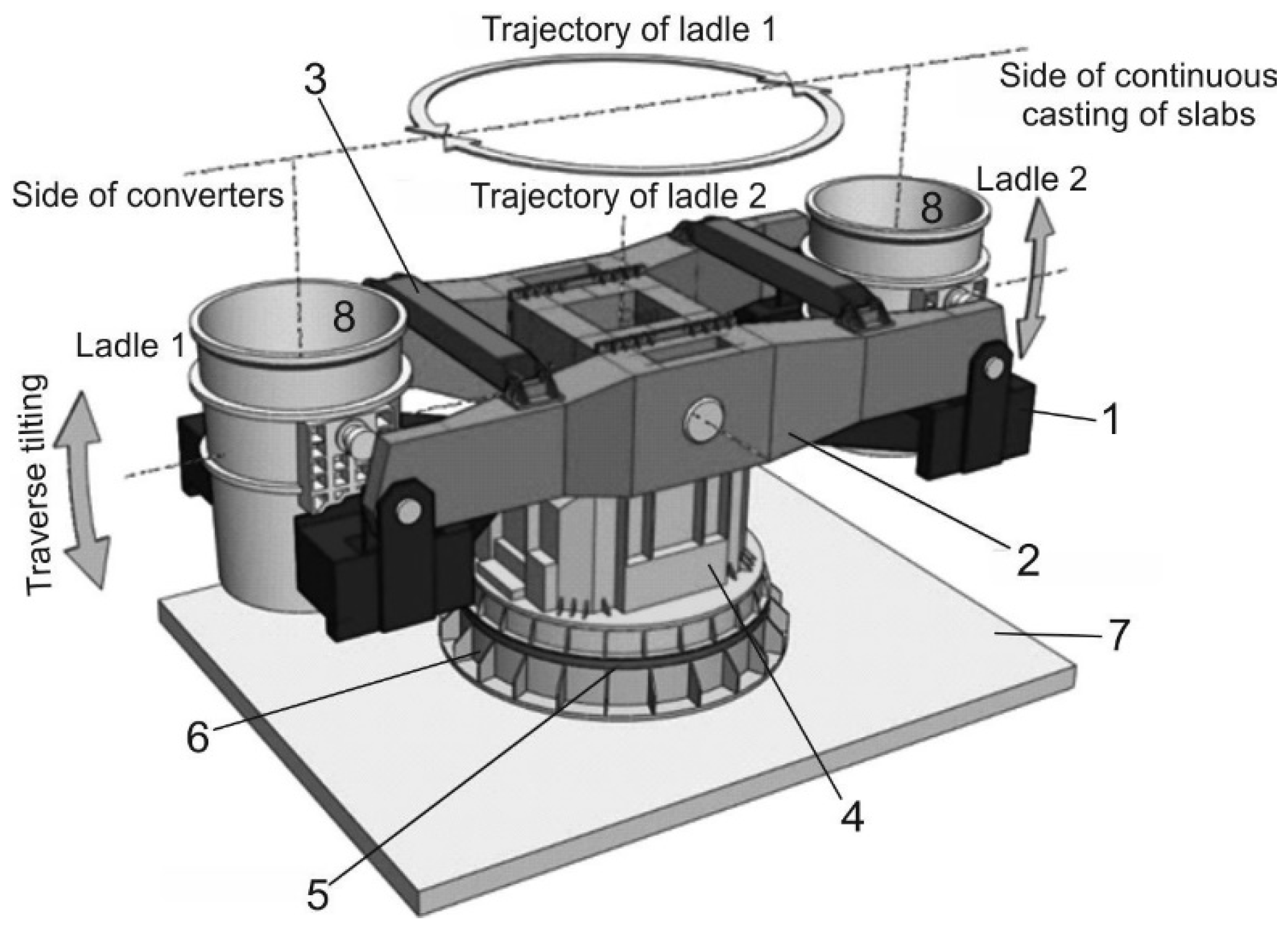
2. Introduction to the Anchoring of the Casting Pedestal

The continuous casting of slabs is currently the most widely used method, in which the solidification of steel leads to the production of long steel products. Its fundamental principle is that the liquid steel is first infused from a ladle into a tundish and then distributed through many sprues in a vertical direction into water-cooled copper moulds. The ladles, transported by an overhead bridge crane and a casting pedestal, are used to bring the liquid steel from the converter to the tundish. The casting pedestal is used for constraining the casting ladles and their rotation from the reserve (receiving, preparatory) position to the casting (working) position, and vice versa (in the mode of individual melting and in the mode of melting to melting). It also serves to drain the molten steel into the emergency containers in case of a failure of the slide cap, and for lowering and lifting the casting ladles during various technological operations. It is a two-position pedestal realised as a lifting and rotating pedestal with a load cell. The supporting structure of the casting pedestal is formed mainly by steel weldments. Their dimensions and shapes are designed in such a way that after the casting ladle filled with liquid steel is placed in the reserve position, the casting pedestal ensures its transfer around the axis of the casting pedestal to the casting position. After casting the steel from this ladle into the tundish to about 25% of the liquid steel content, the second full pan can be placed on the other/opposite traverse side (in the reserve position). If there is only molten slag left in the casting ladle (approximately 7000 kg), the pedestal is rotated so that the full ladle is moved from the reserve position to the casting position.
Selected technical characteristics of the assessed casting pedestal (Figure 1) are:
Maximum weight of the casting ladle with metal (steel)260,000 kg
Weight of empty ladle70,000 kg
Ladle lift height800 mm
Pedestal angular velocity1 rpm
Maximum angle of rotation230°
Roller track mean diameter6400 mm
As part of the overhaul of the casting pedestal, some supporting members were replaced, but replacement of the anchor bolts embedded in the concrete foundation was not possible. When the original structure was disassembled, damage to the first threads on the concrete foundation side of some of the anchor bolts was found. As already mentioned, their replacement was not possible, or very difficult. Therefore, it was necessary to design another solution to achieve safe operation at the required bolted joint preload. By numerical modelling, a design modification of the nut was proposed to lighten the first threads. Subsequently, experimental measurements were carried out, taking into account real operational conditions. Based on the results obtained, conclusions were drawn on the further operation of the casting pedestal. The value of the considered preload of 180 kN in the bolted joints was taken from the original static calculation.
Figure 2 shows the layout of three types of anchor bolts (34 anchor bolts in total) with basic dimensions, which are used to fix the casting pedestal to the concrete foundation. For this reason, it was necessary to design the methodology of re-anchoring the casting pedestal so as not to damage the bolted connections (releasing the bolts in the concrete foundation), the repair of which would be not only technically and financially very difficult, but also time-consuming.
In addition to the machining method, the lifespan of the anchor bolts under investigation is influenced, in particular, by the impact of notched effects, which is most significant and unfavourable during the fatigue loading of machine parts and structures. In the case of the bolt and nut, according to Figure 3, the decisive design notches are in the following places:
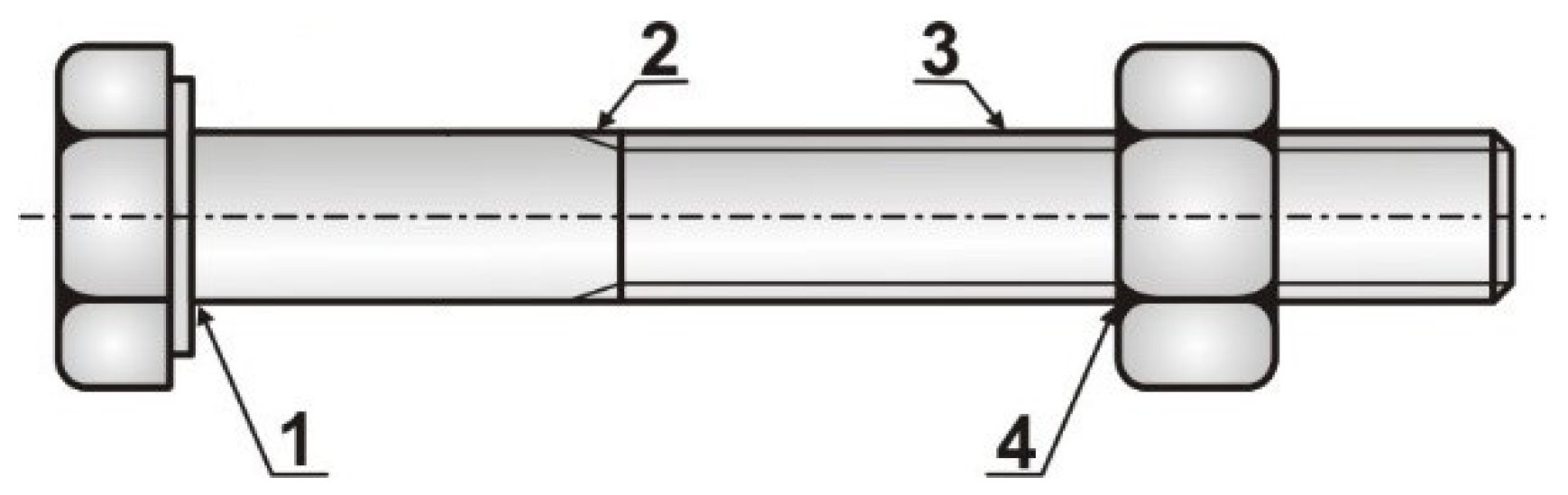
  • Location 1—passage of the cylindrical part of the bolt to the head—this location is absent from the anchor bolts;
  • Location 2—thread runout;
  • Location 3—thread;
  • Location 4—bolt thread at the first nut’s support thread (the most common cause of failure).
The fatigue notch factor is most significant in the bolt thread at Location 4. This fact is related to the stress distribution in the bolt thread, which changes significantly in the part of the thread bolted into the nut. The change in stress distribution is caused by the uneven force distribution in the bolt on the individual threads (Figure 4) due to the different deformations of the bolt and nut. The first thread of the nut and the corresponding cross-section of the bolt are the most loaded. As a result, the first load-bearing thread exhibits the most significant notch effect, which is caused by the load from the force flow in the shank and the local bending of this most loaded thread.
The fatigue notch factor for the threaded part of the bolt depends on the mechanical properties of the bolt, the technologies of its production, the shape of the thread profile, its surface, and the type and height of the nut. From the tests of bolted joints in which the fracture occurs at Location 4 (Figure 3), it is possible to derive a four- to eight-fold notch effect.
In this paper, a methodology for achieving the required bolted joint preload is proposed and experimentally verified, taking into account the damage to the threads on the bolt. The proposed design modification of the nut achieved the relieving of the first (damaged) threads on the bolt, thus ensuring the safe and reliable operation of the casting pedestal anchoring.

3. Materials and Methods

The aim was to design and experimentally verify a methodology for applying the required preload in the anchor bolts of a casting pedestal that had been in operation for less than 30 years. The authors assumed real operational conditions where it was impossible to perform the test tightening of nuts exceeding the allowable values of axial forces in the bolts, as they could not be released from the concrete foundation. In such a case, the new casting pedestal, and thus the entire production, would be undesirably shut down. When proposing the methodology, the authors utilised proven knowledge obtained from the failure of bolted joints, where in similar cases, the damage most often occured at the place of the first load-bearing thread (see Figure 3). Nuts with notches were designed and subsequently fabricated using numerical modelling based on the finite element method to achieve the required preload. The notch was used to provide a relieving of the first threads (Figure 5b). A methodology for measuring the axial forces in the anchor bolts under the operational load was proposed and experimentally verified using dynamometers to verify the functionality of the bolted joint (set preload) and assess the safe operation of the casting pedestal. Before tightening the nuts, a strength calculation of the preloaded anchor bolts was performed to assess their safe operation, taking into account the loading history to date (see Appendix A).

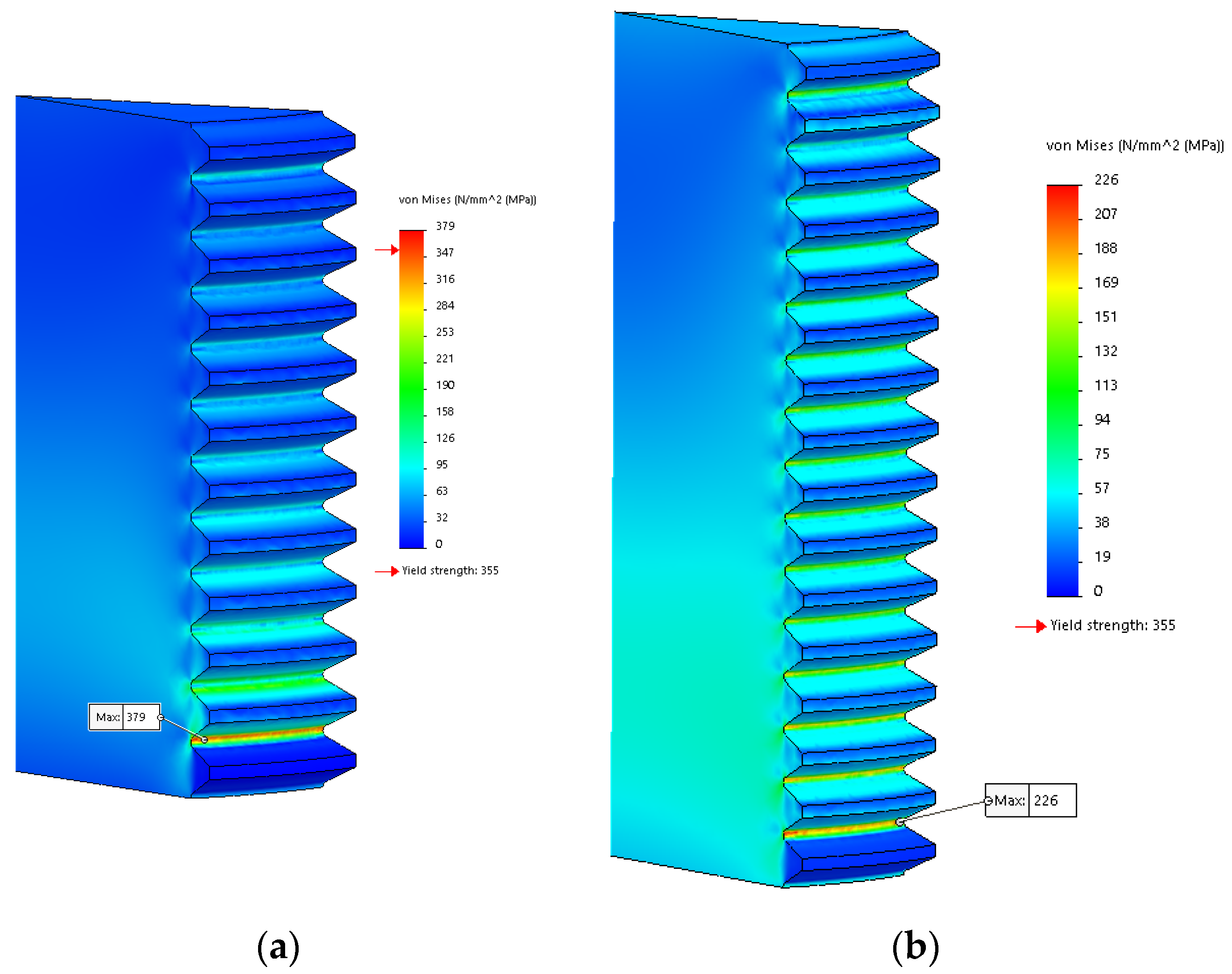
4. Proposal of Nuts Modification Using Finite Element Method (FEM)

To reduce the significant notch effect of the normalised thread as much as possible, it was necessary to ensure the best possible quality of its surface at the root of the profile, and to reduce the relative load on the first and second threads. This can be done through structural modifications based on the idea of changing the deformation stiffness of the nut around the first threads. By reducing the cross-sectional area of the nut (contact of the nut with the washer), the conditions for the bending expansion of the nut were created. In addition, when the normalised nut is tightened to higher torque, plastic deformations and the compression of the first co-locking threads on the nut and bolt occur. Depending on the magnitude of these undesirable phenomena, damage to the bolts occur, which in the case of anchor bolts are extremely technically demanding to replace. Therefore, the authors’ attention was on achieving an optimum stress distribution of the co-collecting threads of the nut and bolt. Figure 5a shows the model of the normalised nut M56, and Figure 5b shows the nut with the notch formed. As the first threads were relieved, to create a notch with the required dimensions, it was necessary to change the outer dimensions and the total number of threads in the nut, as shown in Figure 5b. The proposal of the outer dimensions was based on the dimensions of the torque wrench head (Enerpac HXD 120-CC1290).
Figure 6a,b show the bolted joint model with the finite element mesh formed and the boundary conditions defined. By using symmetry, only 1/12 of the overall model was modelled. The nut was simply supported and the bolt was loaded by the force equal to 15,000 N. The mesh of normalised nut M56 consisted of approximately 155,000 volume finite elements with quadratic approximations, and approximately 230,000 nodes. The mesh of the nut with the notch consisted of approximately 456,000 volume finite elements with quadratic approximations, and approximately 668,000 nodes.
The FEM was a qualitative comparison of stress levels for different nut shapes, so for this reason only a static analysis with linear elastic material behaviour was performed. The material properties of the bolt and nut were the same, i.e., the yield strength was 355 MPa and Young’s modulus was E = 2 10 5 MPa , respectively. Figure 7a,b show details of the equivalent stress fields around the first relieved threads. From comparing the values of the maximum equivalent stresses around the thread root, it is clear that the above modification resulted in a reduction of equivalent stress by approximately 40%. When designing the dimensions and shape of the notch, the technological procedure of its production was taken into account.

5. Experimental Analysis of the Interaction of Anchor Bolts and Concrete Foundation

For experimental measurements, special dynamometers were designed and manufactured to register the magnitude of the axial force in the bolts during nut tightening. The dynamometer is placed between the nut and the supporting structure. The value of the tightening torque induced by the torque wrench is determined based on the appropriate gearing supplied by its manufacturer. Since experimental measurement aimed to determine the magnitude of axial force in the bolt, it was necessary to calibrate the dynamometers and determine the dependence between the value of pressure in the device and the axial force in the bolt prior to the measurement.

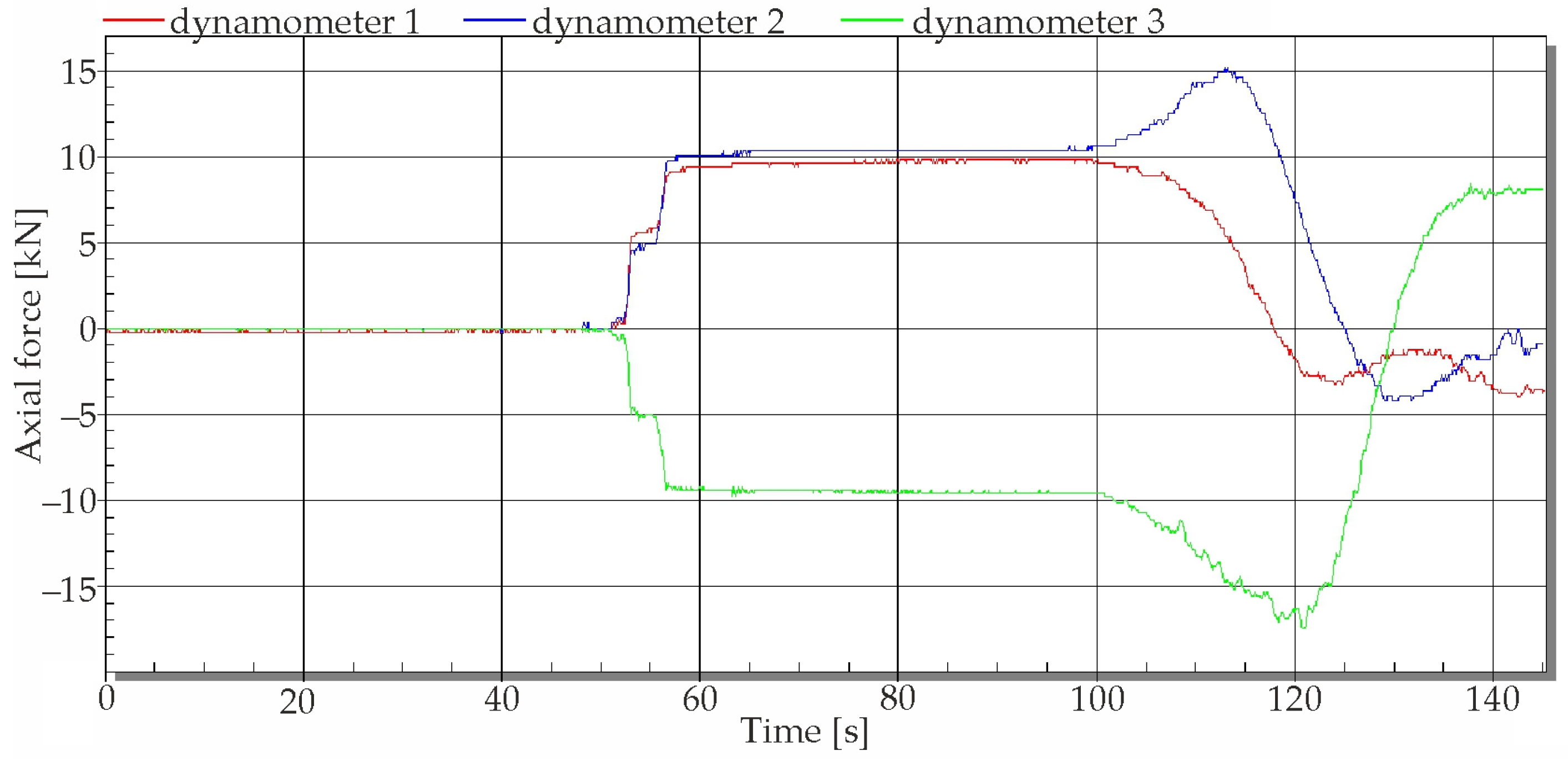
5.1. Measurement under Static Loading

This testing methodology consists of gradually increasing the pressure in the torque wrench from 0 to 60 bar, then 110 bar, then 160 bar, and then finally 200 bar. At each force corresponding to the pressure in the tightening device, a time delay of 5 min was allowed, during which the reading on the strain gauge apparatus was not allowed to increase, confirming the perfect interaction between the anchor bolt and the concrete foundation. The axial forces corresponding to the respective pressures are given in Table 1. At a maximum pressure of 200 bar, with cleaned and lubricated threads, an axial force of 350 kN was achieved according to the calibration diagram for the given state of the threads and their lubrication, and the friction of the nut against the washer. In the testing of the interaction of the anchor bolts with the concrete foundation, newly designed nuts were used by the authors so as to prevent failure of the anchor bolts or plastic deformations at the location of the first load-bearing thread.
The testing of the interactions of the anchor bolts and foundations was carried out by means of dynamometers and newly designed nuts by adjusting the pressure parameter on the hydraulic tightening device, which corresponds to the respective preload. It should be noted that, although there are some variations in the set preloads determined from the calibration diagrams, these differences did not reach 5%.

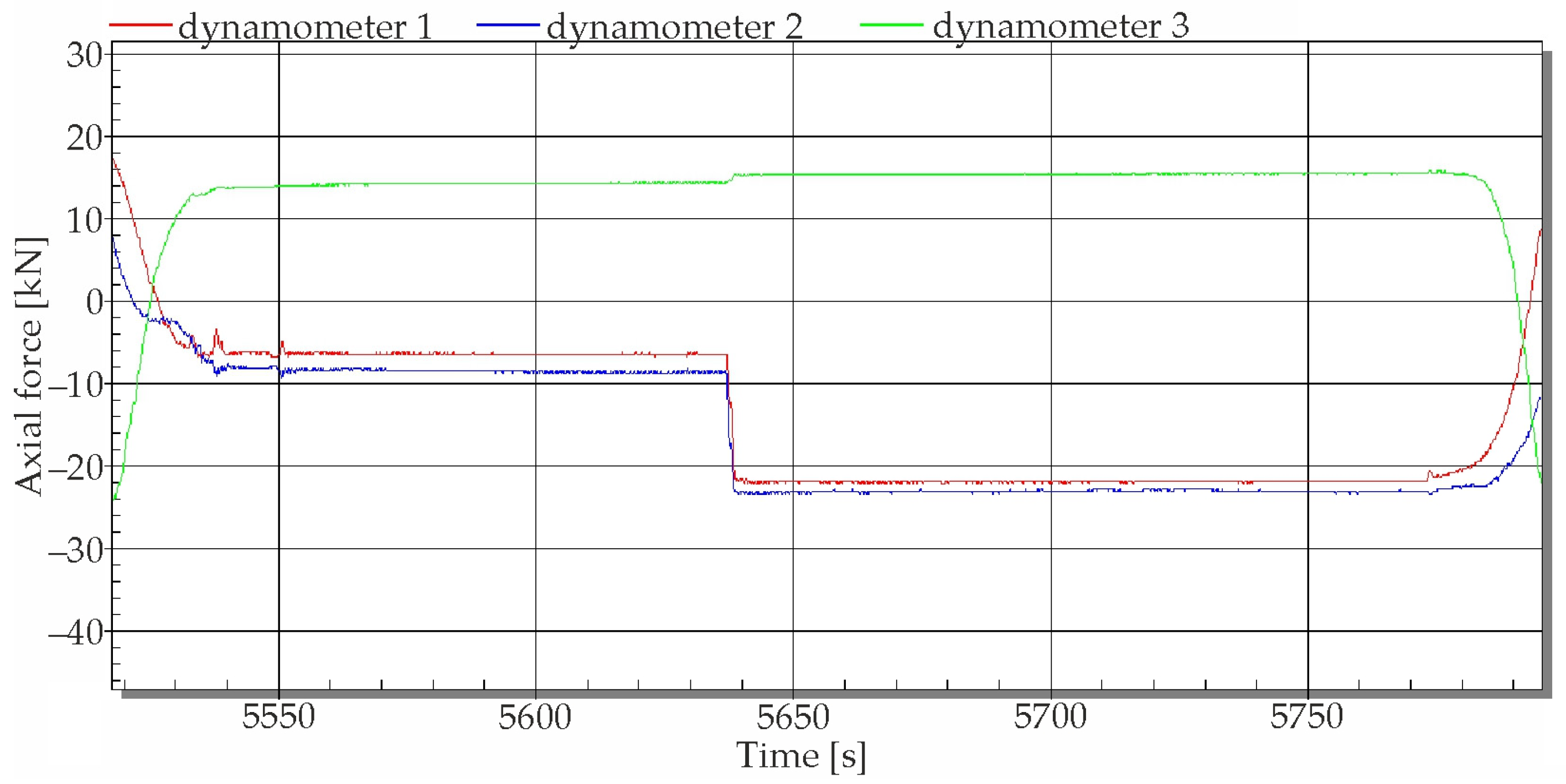
5.2. Measurement at Operational Loading

After a detailed analysis of the condition of the anchor bolts, as well as of the measures taken to relieve the first and the other three bolt threads at the nut location, and also taking into account the previous history of the loading of the anchor bolts, the authors determined the preload forces in the individual anchor bolts as follows:
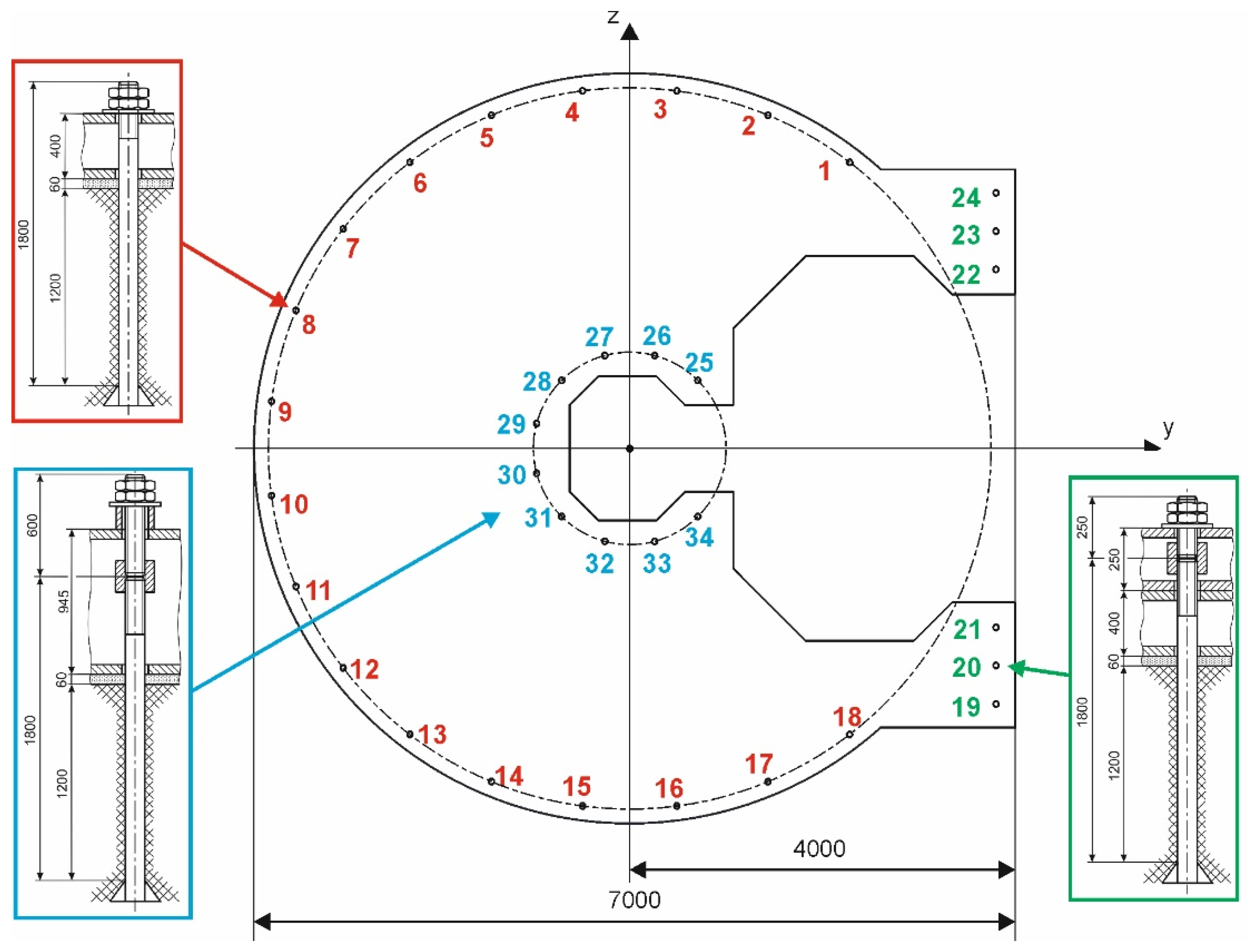
  • Anchor Bolts No. 1 to No. 24 should be preloaded to an axial force corresponding to 200 kN, which corresponds to a given state of bolts, nuts, and washers when defining a pressure value of 120 bar;
  • Anchor Bolts No. 25 to No. 34 should have a preload with regard to the passage of the thread into the shank as well as the flexibility of the supporting structure, and a lower range of operational axial forces of 180 kN, i.e., approximately 110 bar.
Dynamometers 1 to 4 were used to measure the time changes of the axial forces in the anchor bolts on the casting pedestal. When selecting the anchor bolts under consideration, effort was made to remove the most, or nearly the most loaded bolts. Based on the above requirements, anchor Bolts No. 8, No. 11, No. 19 and No. 24 were selected, which are located on the outer contour of the supporting structure, therefore the preload value was selected at 200 kN. The forces in the bolts was identified by dynamometers according to Table 2.
Figure 8 shows the time record of the axial force registered by Dynamometer 3 when tightening the nut to the required preload on Bolt No. 8, with a value of 200 kN.
After putting the casting pedestal into testing operation and balancing the strain gauge apparatus connected to the completed measuring chain, the strain gauge measurement of changes in the axial forces in the anchor bolts began. Unfortunately, the first measurements showed that the cabling on Dynamometer 4 was damaged by the operating personnel. Due to the time duration of the planned outage of the casting pedestal, it was not possible to perform its repair. Therefore, the operational measurement was continued by using only three dynamometers.
The first measurements, which were performed only when rotating the casting pedestal without the ladle in the first and second basket, showed that the changes in the axial forces in the bolts did not exceed 6 kN in these measurements. Although these are forces that cause stress in bolts below 3 MPa, i.e., absolutely negligible components in terms of the resulting stress, they testify not only to the condition of the roller track but also to the stiffness of the supporting structure of the casting pedestal. Figure 9 shows the time courses of changes in the axial forces in Bolts No. 8, No. 19, and No. 24 when rotating the casting pedestal without a ladle in Basket 1 and Basket 2, while the beginning of rotation at approximately 2000 s is from the position of Basket 1 from the reserve to the casting position. After a short interruption of the rotation, the rotation continues and the traverse is lifted. It can be seen from the course that the axial force increments do not return completely to zero after the return of Basket 1 to the reserve position (time 5000 s), which may be caused partly by inaccuracies in the return of the traverse to the same position, and also by the changed geometry due to the position of the rollers on the roller track.
The following section shows the selected time changes of the axial forces in Bolts No. 8, No. 19, and No. 24. The operator used ladles weighing 70,300 kg (empty) and 241,600 kg (full/tare). Figure 10 shows the time changes of the axial forces when loading the empty ladle into Basket 1 in the reserve position at about 50 s after the start of the measurement. It can be seen that a positive increase in axial forces occurred in Bolts No. 19 and No. 24, which is caused by the fact that, after loading the empty ladle, the preload in Bolts No. 19 and No. 24 is reduced, and this is reflected by an increase in the deformation part of the dynamometer, resulting in a positive reading on the strain gauge apparatus. Simply put, if the preload in the bolts were not set, it would not be possible to register a decrease in the axial force. At a time of about 100 s, the rotation of the casting pedestal with an empty ladle in Basket 1 started from the reserve position to the casting position, which caused changes in the polarity of the force increments in the bolts when Basket 1 was moved to the casting position. It is evident from the courses that in this operation the axial force range in Anchor Bolt No. 8 is 25 kN, in Anchor Bolt No. 19 it is 13 kN, and in Anchor Bolt No. 24 it is 19 kN. At the end of the time period (Figure 10), Basket 1 with an empty ladle was in the casting position.
Figure 11 shows the process of rotating the casting pedestal with an empty ladle in Basket 1 to the reserve position, when the empty ladle was removed and the pedestal with a full ladle was rotated to the reserve position again.
In order to assess the safe operation of the casting pedestal, the following operational modes were examined:
  • Rotation of the pedestal without a ladle in Baskets 1 and 2;
  • Loading the empty ladle with subsequent rotation, and lifting of the ladle in the casting position in Basket 1 and subsequently in Basket 2;
  • Loading a full ladle weighing 241,600 kg into Basket 1 and subsequently into Basket 2, rotating the pedestal, and lifting and launching the basket with the ladle;
  • Loading the empty and full ladle and handling the pedestal, including the replaced ladles in baskets.
After analysing the time records of changes in the axial forces in the bolts in the above-mentioned operational modes of the pedestal, it was found that the maximum range of changes in the axial forces Δ N i in the measured bolts is the following: Δ N 8 = 61 kN , Δ N 19 = 60 kN , Δ N 24 = 61 kN .

6. Discussion

As mentioned above, the operational measurements of the time changes of the axial forces were carried out with an empty ladle weight of 70,300 kg and a full ladle weight of 241,600 kg. In the technical characteristics of the casting pedestal defined by the operator, the values of an empty ladle at 70,000 kg and a full ladle at 260,000 kg were defined, which represents a difference of 0.43% in the case of an empty ladle, but in the case of a full ladle its maximum possible weight is 7.1% higher, thus the stress and strain fields in the elastic behaviour of the structure will be higher according to the stated difference, including axial forces. Therefore, in the subsequent analysis, it was necessary to consider their increase by 7.1% at the measured maximum values of an axial force range of 61 kN, i.e., with increased range Δ N max = 65 kN .
Another particularly serious fact is that for the material of the bolt at S355JR, the fatigue limits in an alternately symmetrical and disappearing cycle are defined by the value of σ c = 178.5 MPa and σ H c = 305 MPa , and when determining the limiting upper stress according to the simplified Haigh diagram already at the actual preload set (200 kN) and the maximum increase in axial force increased by 7%, the maximum value of the upper stress σ h B in bolt will be:
σ h B = ( 200 + 65 ) 10 3 2050.3 = 129.2 MPa
thus, the mean stress is:
σ m B = 64.6 MPa .
In accordance with the fatigue curve for the material values of the bolt (see Appendix A), the number of cycles will be up to failure N * = 124,700 , thus, in the implementation of 35 melts per day, the lifespan of the bolts of the casting pedestal will be approximately 3560 days.
From the analysis of the critical points on the anchor bolts, it can be seen that the replacement of the original nuts with new nuts played a very important role, as the first thread of the bolt in the nut is more than twice as sensitive to the occurrence of a failure as the thread termination point. The anchor bolt’s failure limit is determined by a location which, despite the frequent occurrence of the failure, is a much safer cross-section.
The experimental determination of axial force ranges has shown that the calculation of the forces in the anchor bolts ensures a high value of anchor safety. On the other hand, the force measurement methodology and the interpretation of the results achieved, including a comprehensive view of anchoring safety, provides relevant evidence of the functionality and effectiveness of the proposed solution.
In order to ensure safe operation of the anchoring during the lifespan of new parts for the casting pedestal, and taking into account the accumulation of damage to the anchoring bolts to date, it is necessary to apply the current recommendation of the authors that, when placing a full ladle in the casting pedestal and when rotating it, there should always be an empty ladle or a ladle with molten slag in the other basket. Otherwise, if a full ladle is always loaded into the casting pedestal and there is not at least an empty ladle on the other side, the lifespan of the anchoring will be reduced to about one third.

Author Contributions

Conceptualization, M.P., A.S. and P.L.; methodology, M.P. and P.L.; validation, M.P., P.L. and P.Š.; formal analysis, M.P., P.Š. and A.S.; investigation, M.P., P.L. and M.H.; resources, P.L., M.H. and P.Š.; draft preparation, M.P. and P.L.; writing—review and editing, M.H. and M.P.; visualization, M.H. and A.S.; project administration, M.P.; funding acquisition, M.P. All authors have read and agreed to the published version of the manuscript.

Funding

This paper was supported by the Ministry of Education of Slovakia Foundation under grant projects VEGA No. 1/0141/20, VEGA No. 1/0500/20, and VEGA No. 1/0330/19.

Institutional Review Board Statement

Not applicable.

Informed Consent Statement

Not applicable.

Data Availability Statement

Not applicable.

Conflicts of Interest
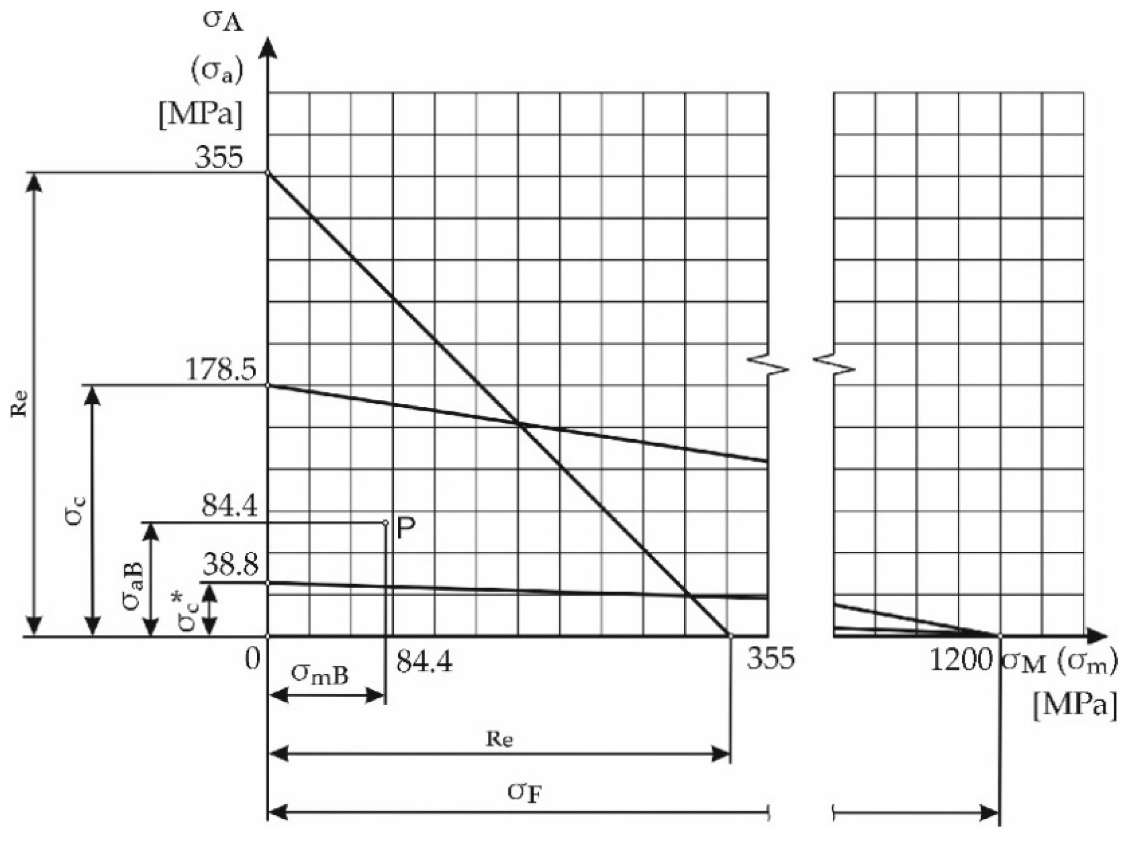
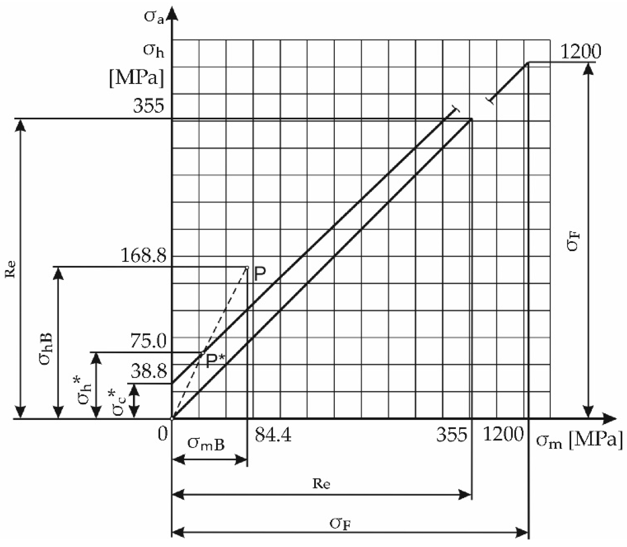
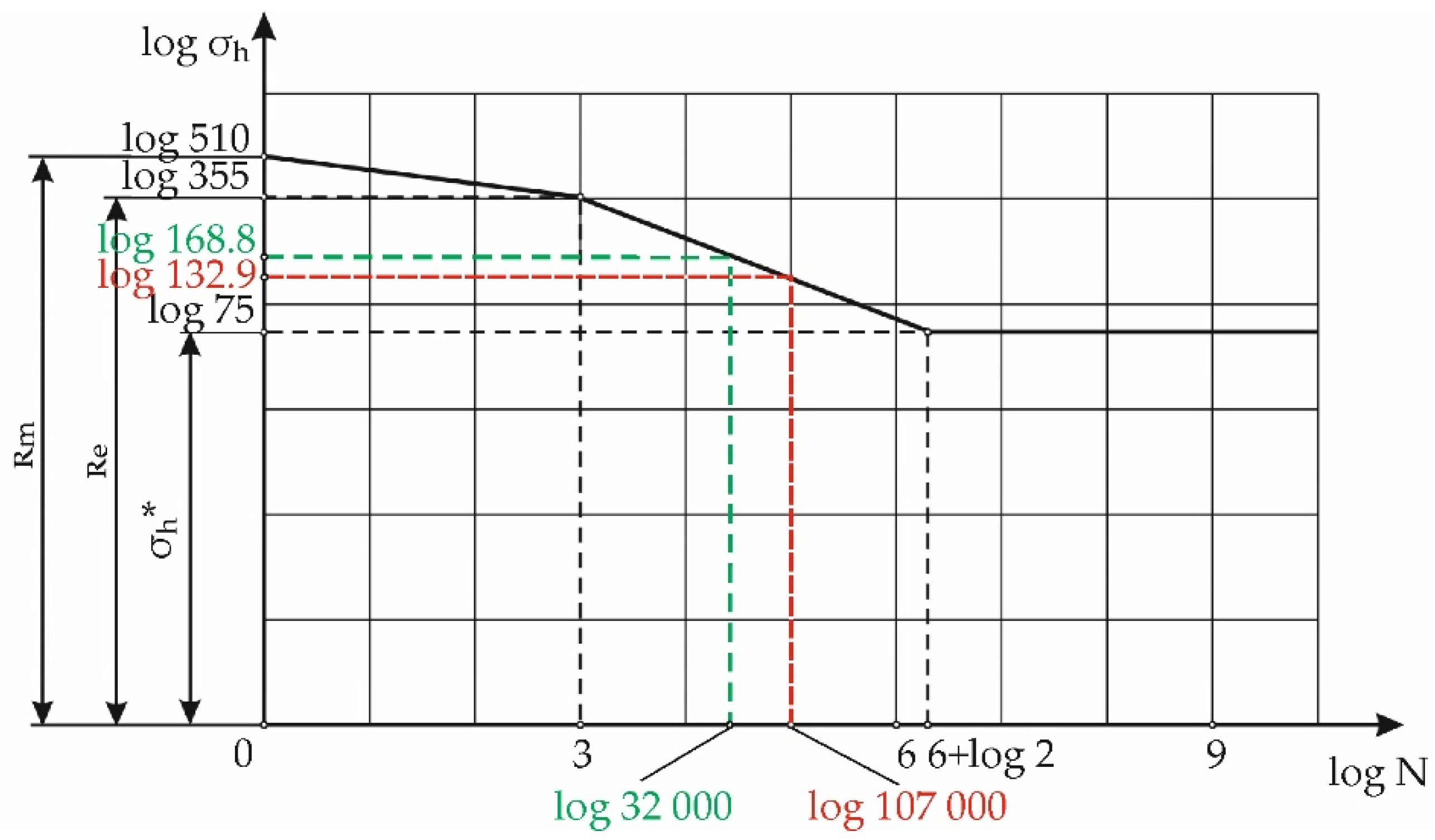
The authors declare no conflict of interest.

Appendix A

For the verification of the data about the mechanical properties of the anchoring bolts, indicative measurements using Brinell hardness tests were carried out. The measured values of the diameters of the impressions on the anchor bolt corresponded to a strength Rm of approximately 510 MPa; according to the above, the material of the anchor bolts is close to steel at S355JR. The yield strength is 355 MPa, ductility (reduction in area) 22%, and Young’s modulus is E = 2 10 5 MPa .
The allowable tensile stress for anchor bolt σ D B materials is
σ D B = R e k e = 355 1.3 = 273 MPa
where R e is yield strength and k e is the safety factor against yielding by tensile loading. In the case of steel bolts according to [24] we chose safety factor against yielding in the interval from k e = 1.3 ÷ 1.5 (the authors chose 1.3).
The bolt is loaded by normal tensile stress from the maximum force in the bolt and by the shear stress from the frictional torque on the thread (torsion). For the most unfavourable case of loading during operation, where there is a full ladle on one side and no ladle on the other side, the maximum value of the force in the most loaded Bolts No. 9 and No. 10 (see Figure 2) is equal to:
F max = 346 kN .
The value of the maximum normal tensile stress induced by the maximum force F max in the bolt:
σ t , max = F max A min = 346 10 6 2050.3 = 168.8 MPa
where A min is the cross-section of the bolt core.
The maximum shear stress from the frictional torque in the thread of the anchor bolt is equal to:
τ max = M f Z P = 68.7 MPa
where M f is the torque required to overcome the friction on the thread from a preload force of 180 kN, Z P is the polar modulus.
The principal stresses in the anchor bolt are:
σ 1 , 3 = 168.8 2 ± ( 168.8 2 ) 2 + 68.7 2 ,
where σ 1 = 193.2 MPa and σ 3 = 24.4 MPa .
The equivalent stress for the anchor bolt according to von Mises’ strength theory is equal to:
σ e q v v o n M i s e s = 206.5 MPa
The strength condition σ e q v v o n M i s e s σ D for the anchor bolt is met. On the other hand, it should be seen that the value of the equivalent stress is relatively high and the value of the allowable stress at the chosen safety level 1.3 differs by 32%. With a chosen safety level of 1.5, the maximum load would be only 14% lower than the allowable stress; therefore, in such extremely loaded structures, it is necessary to reduce the stresses in the anchor bolt, which can be achieved by reducing the shear stress from the frictional torque in the thread through lubrication. With a lubricated thread on the anchor bolt, the maximum shear stress from the frictional torque in the thread will be lower and the reserve will be significantly higher.
The above calculation was performed under static loading. However, cycling (disappearing) loading of the anchor bolts occurs when the casting pedestal is rotated. The most loaded anchor bolt transmits a pulsating tensile axial force with a mean value F m B of:
F m B = F max B + F min B 2 = 346 + 0 2 = 173 kN
with amplitude F a B :
F a B = F max B F min B 2 = 346 0 2 = 173 kN ,
where F max B and F min B are the maximum and minimum value of the axial force in the bolt during operation.
The corresponding mean value of the normal stress σ m B = 84.4 MPa , amplitude σ a B = 84.4 MPa , and maximum stress σ max B = 168.8 MPa .
The anchor bolt is simultaneously loaded by a static shear stress τ max B = 68.7 MPa .
A simplified Haigh diagram (Figure A1) has been constructed to determine safety under the cycling tensile loading of the anchor bolt. The values given in the diagram for the anchor bolts are based on the data of the mechanical properties of the bolt, as well as other parameters reducing the fatigue strength of the material. Considered values:
Yield strength R e = 355 MPa ;
Tensile strength R m = 510 MPa ;
Fatigue limit σ c = 178.5 MPa ;
Fatigue limit for the disappearing cycle σ H c = 305 MPa ;
Surface quality factor η p = 0.87 MPa ;
Fatigue notch factor of Notch 4 was set to β = 4
Thus, the fatigue limit of the anchor bolt at the location of the first nut’s thread is:
σ c * = σ c η p β = 178.5 0.87 4 = 38.8 MPa .
Figure A1. Simplified Haigh diagram for an anchor bolt.
Applsci 11 11399 g0a1
The fictitious strength σ F needed for the simplified Haigh diagram is determined on the basis of the relationship:
σ F = σ c σ H c 2 σ c σ H c = 1186 MPa .
From Figure A2 it can be seen that the operating point P ( σ m k , σ a k ) lies outside the safe operating area for an unlimited number of load cycles. The value of σ h * = 75 MPa required for the fatigue curve is determined from the simplified Smith diagram of Figure A2.
Figure A2. Simplified Smith diagram for an anchor bolt.
Applsci 11 11399 g0a2
Since the anchor bolt has a limited lifespan, it is necessary to determine the number of cycles to failure from the fatigue curve for the maximum value of stress in the bolt under a disappearing load. In Figure A3, the fatigue curve of the anchor bolt under a disappearing load is shown.
Figure A3. The fatigue curve of the anchor bolt under a disappearing load.
Applsci 11 11399 g0a3
From the fatigue curve shown in Figure A3, the number of cycles to failure can be determined. The number of cycles to failure for the maximum stress levels (168.8 MPa) in the anchor bolt is N = 32,000 cycles. The results of the calculation show that when operating a casting pedestal with the most unfavourable combination of loads (Basket 1 with a full ladle, Basket 2 empty) assuming 35 melts per day, the lifespan of the anchor bolts would be approximately 910 working days. For this reason, the authors recommend operating the casting pedestal in the mode of one basket full, and in the other basket an empty ladle (without liquid steel). In this case, with the same calculation procedure, the lifespan of the most loaded anchor bolts is increased to approximately 107,000 cycles, which corresponds to a lifespan of approximately 3060 working days for the casting pedestal at 35 melts per day. Since no other loading on the casting pedestal can occur, the safety of the anchor bolt can only be ensured up to a specified number of cycles.

References

  1. Design Guide 1: Base Plate and Anchor Rod Design, 2nd ed.; American Institute of Steel Construction: Chicago, IL, USA, 2006; Available online: https://www.aisc.org/Design-Guide-1-Base-Plate-and-Anchor-Rod-Design-Second-Edition (accessed on 21 June 2021).
  2. Design of Fastenings in Concrete—Design Guide—Parts 1 to 3; Part 1; 1997; ISBN 978-0-7277-2558-5. Available online: https://www.fib-international.org/publications/ceb-bulletins/design-of-fastenings-in-concrete-pdf-detail.html (accessed on 21 November 2021).
  3. EN 1993-1-8:2005—Eurocode 3: Design of Steel Structures Part 1–8: Design of Joints. Available online: https://standards.iteh.ai/catalog/standards/cen/312c51d1-0813-4e29-b1dd-5db5f15e2497/en-1993-1-8-2005 (accessed on 21 June 2021).
  4. Delhomme, F.; Debicki, G.; Chaib, Z. Experimental Behaviour of Anchor Bolts under Pullout and Relaxation Tests. Constr. Build. Mater. 2010, 24, 266–274. [Google Scholar] [CrossRef]
  5. Li, Y.; Liu, C. Experimental Study on the Shear Behavior of Fully Grouted Bolts. Constr. Build. Mater. 2019, 223, 1123–1134. [Google Scholar] [CrossRef]
  6. Gong, Y.; Ding, Q.; Yang, Z.-G. Failure Analysis on Premature Fracture of Anchor Bolts in Seawater Booster Pump of Nuclear Power Plant. Eng. Fail. Anal. 2019, 97, 10–19. [Google Scholar] [CrossRef]
  7. Feng, X.; Zhang, N.; Yang, S.; He, F. Mechanical Response of Fully Bonded Bolts under Cyclic Load. Int. J. Rock Mech. Min. Sci. 2018, 109, 138–154. [Google Scholar] [CrossRef]
  8. Gabáni, Ľ.; Trebuňa, F.; Šimčák, F.; Bocko, J.; Pástor, M. Using Experimental Methods of Mechanics for Failure Prediction of Casting Pedestal. Acta Mech. Slovaca 2015, 19, 42–50. [Google Scholar] [CrossRef]
  9. Pástor, M.; Trebuňa, F.; Šimčák, F.; Buršák, M.; Šarga, P.; Gabáni, Ľ. Proposal of Methodology and Calibration of Dynamometers for Quantification of Forces in Anchor Bolts. Acta Mech. Slovaca 2014, 18, 14–19. [Google Scholar] [CrossRef]
  10. Wang, D.S.; Liu, A.Q. Study on the Performance of Full-Length Pre-Stressed Anchor Bolts. Adv. Mater. Res. 2013, 639–640, 765–769. [Google Scholar] [CrossRef]
  11. Liu, Q.; Chai, J.; Chen, S.; Zhang, D.; Yuan, Q.; Wang, S. Monitoring and Correction of the Stress in an Anchor Bolt Based on Pulse Pre-Pumped Brillouin Optical Time Domain Analysis. Energy Sci. Eng. 2020, 8, 2011–2023. [Google Scholar] [CrossRef]
  12. Huang, M.H.; Zhao, M.H.; Chen, C.F. Influence of anchorage length on stress in bolt and its critical value calculation. Rock Soil Mech. 2018, 39, 4033–4041. [Google Scholar]
  13. Yang, S.S.; Cao, J.P. Evolution mechanism of anchoring stress and its correlation with anchoring length. J. Min. Saf. Eng. 2010, 27, 1–7. [Google Scholar]
  14. Wen, Z.; Shi, Y.; Cui, Z.-D.; Wang, R.-C. Study of Stress Features of Fully Grouted Prestressed Anchors. Rock Soil Mech. 2010, 31, 177–181. [Google Scholar]
  15. Sapieta, M.; Sapietova, A.; Gajdos, L. Determine the Fatigue Life of Flange of Bearings Test Station. Procedia Eng. 2017, 177, 548–553. [Google Scholar] [CrossRef]
  16. Trebuňa, F.; Šimčák, F.; Bocko, J. Decreasing of Vibration Amplitudes of the Converter Pedestal by Design Changes and Changes in Prestress of the Bolted Joints. Eng. Fail. Anal. 2009, 16, 262–272. [Google Scholar] [CrossRef]
  17. Tizani, W.; Rahman, N.A.; Pitrakkos, T. Fatigue Life of an Anchored Blind-Bolt Loaded in Tension. J. Constr. Steel Res. 2014, 93, 1–8. [Google Scholar] [CrossRef] [Green Version]
  18. Shen, X.; Lu, L.; Zeng, D. Fatigue Failure Analysis of High Strength Bolts Used for High-Speed Railway Vehicle Braking Discs. Eng. Fail. Anal. 2020, 115, 104661. [Google Scholar] [CrossRef]
  19. Choi, J.; Kim, B. Failure Analysis of Anchor Bolt of Rail Fastening System for Direct Fixation Track. Eng. Fail. Anal. 2020, 112, 104513. [Google Scholar] [CrossRef]
  20. Miao, R.; Shen, R.; Zhang, S.; Xue, S. A Review of Bolt Tightening Force Measurement and Loosening Detection. Sensors 2020, 20, 3165. [Google Scholar] [CrossRef]
  21. Bocko, J.; Čarák, P.; Čajka, M. Analysis of Stress and Deformation States in Bolted Joints with Prestress. Am. J. Mech. Eng. 2016, 4, 241–246. [Google Scholar] [CrossRef]
  22. Lin, S.-R.; Wu, W.-F. Estimation of Maximum Axial Force of Anchor Bolts in Consideration of Random Bolt Failures. Int. J. Press. Vessel. Pip. 2015, 131, 52–59. [Google Scholar] [CrossRef]
  23. Zheng, X.G.; Zhang, N.; Xue, F. Study on stress distribution law in anchoring section of prestressed bolt. J. Min. Saf. Eng. 2012, 29, 365–370. [Google Scholar]
  24. Konstrukce Strojů a Zařízení I: Spojovací Části Strojů: Návrh, Výpočet, Konstrukce/Zdeněk Dejl Portaro Katalog Knihovny. Available online: https://katalog.vsb.cz/documents/46509 (accessed on 21 June 2021).
Figure 1. Basic parts of the casting pedestal: 1—hinging supporting baskets; 2—traverse beams; 3—connecting rods; 4—bearing support pedestals; 5—roller bed; 6—supporting structure; 7—concrete foundation; 8—casting ladles.
Applsci 11 11399 g001
Figure 2. Layout of anchor bolts and their basic dimensions.
Applsci 11 11399 g002
Figure 3. Notch locations on the bolt.
Applsci 11 11399 g003
Figure 4. The uneven force F distribution in the threads.
Applsci 11 11399 g004
Figure 5. Sections through the analysed matrices: (a) normalised nut; (b) modified nut with the designed notch.
Applsci 11 11399 g005
Figure 6. 1/12 of the overall model: (a) normalised nut; (b) designed nut.
Applsci 11 11399 g006
Figure 7. Fields of equivalent stress around the root of the first thread on the anchor bolt when using: (a) normalised nut; (b) designed nut.
Applsci 11 11399 g007
Figure 8. Tightening nut No. 8 according to the required preload of 200 kN registered by Dynamometer 3.
Applsci 11 11399 g008
Figure 9. Recording of time changes of axial forces when rotating the casting pedestal with empty baskets.
Applsci 11 11399 g009
Figure 10. The time courses of axial forces in Bolts No. 8, No. 19, and No. 24 when loading the empty ladle into Basket 1 and rotating the pedestal to the casting position.
Applsci 11 11399 g010
Figure 11. The time courses of the axial forces when removing the empty ladle and rotating the pedestal with the full ladle to the reserve position.
Applsci 11 11399 g011
Table 1. Axial forces at defined pressures.
Tightening Device Pressure [bar]Axial Force in Bolt [kN]
6093
110178
160266
200345
Table 2. Assignment of dynamometers to anchor bolts.
Anchor BoltDynamometer
191
242
83
114
Publisher’s Note: MDPI stays neutral with regard to jurisdictional claims in published maps and institutional affiliations.

