
Efficient Key-Value Data Placement for ZNS SSD


Abstract
:1. Introduction
2. Background
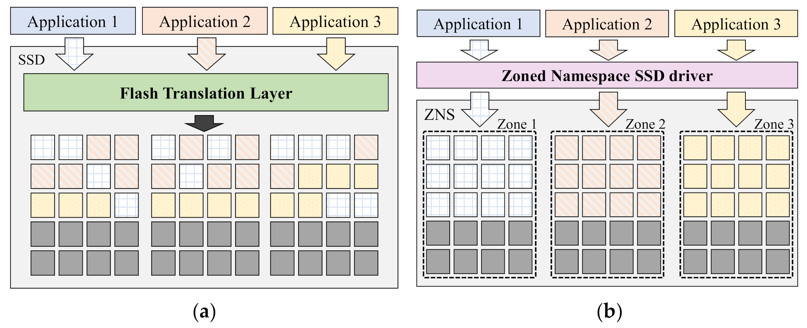
2.1. Zoned Namespace Solid-State Drive (SSD)
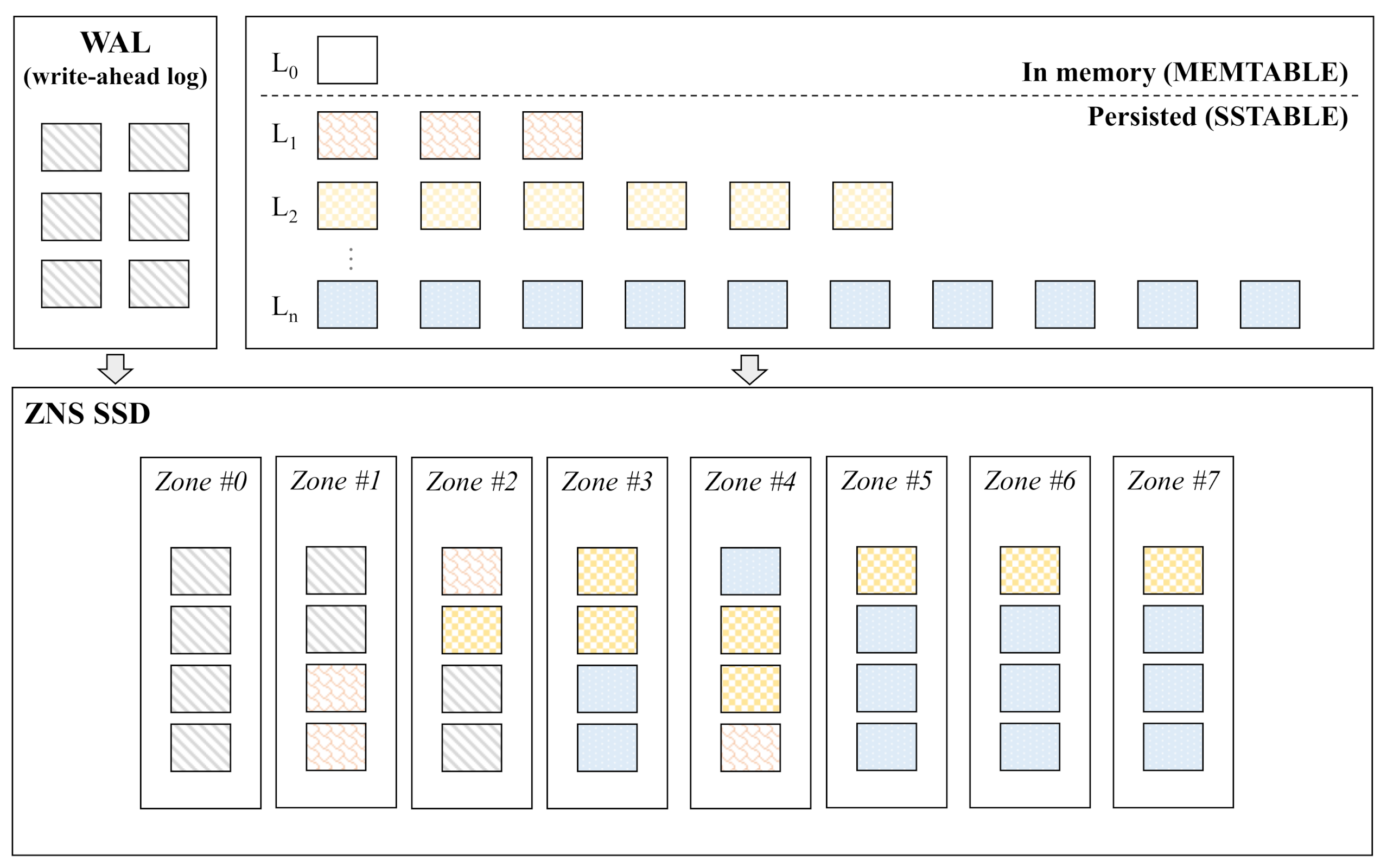
2.2. RocksDB
3. Motivation
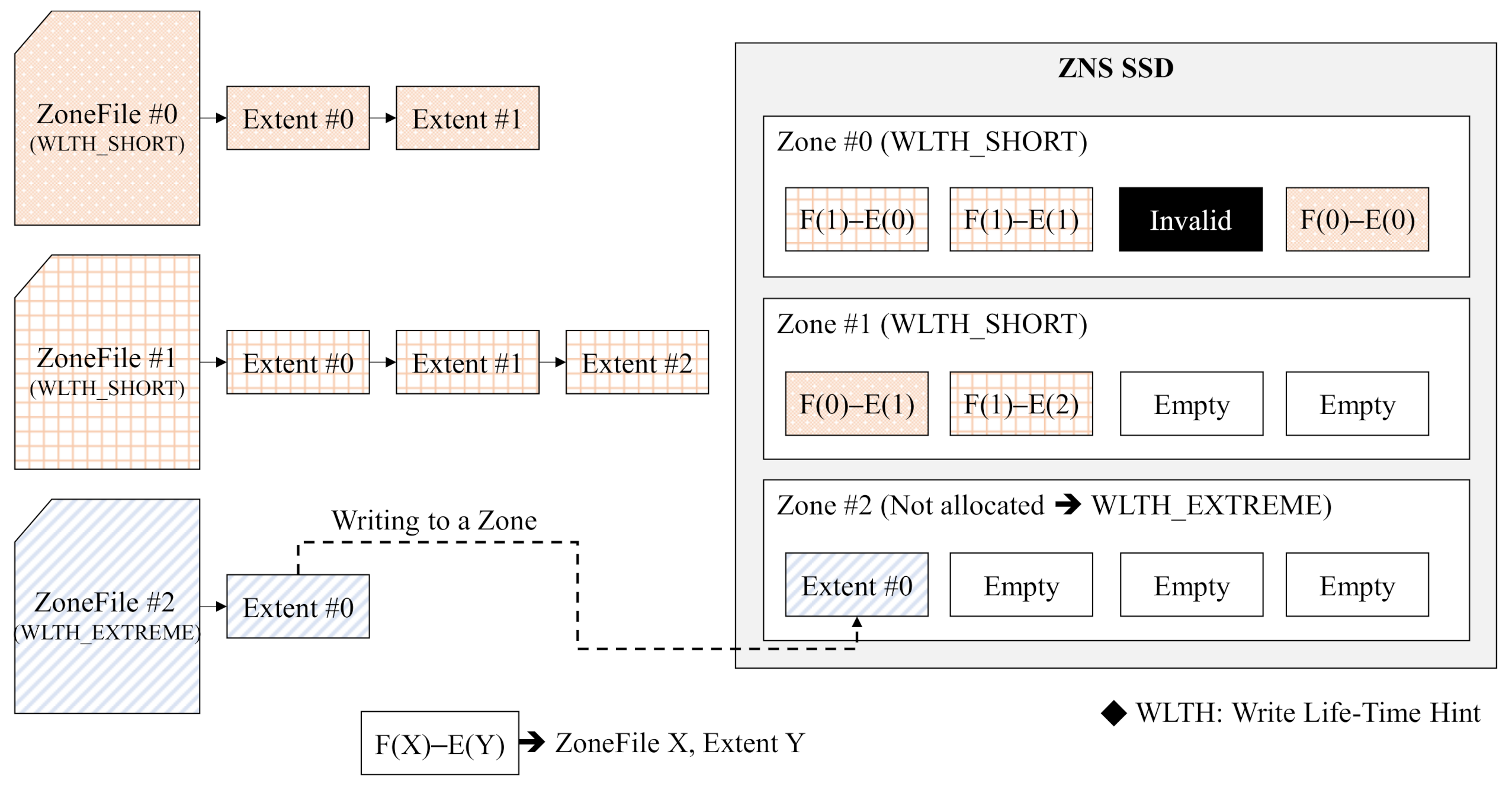
3.1. ZenFS
3.2. Limitations of ZenFS
4. Design
4.1. Lifetime-Based Zone Allocation
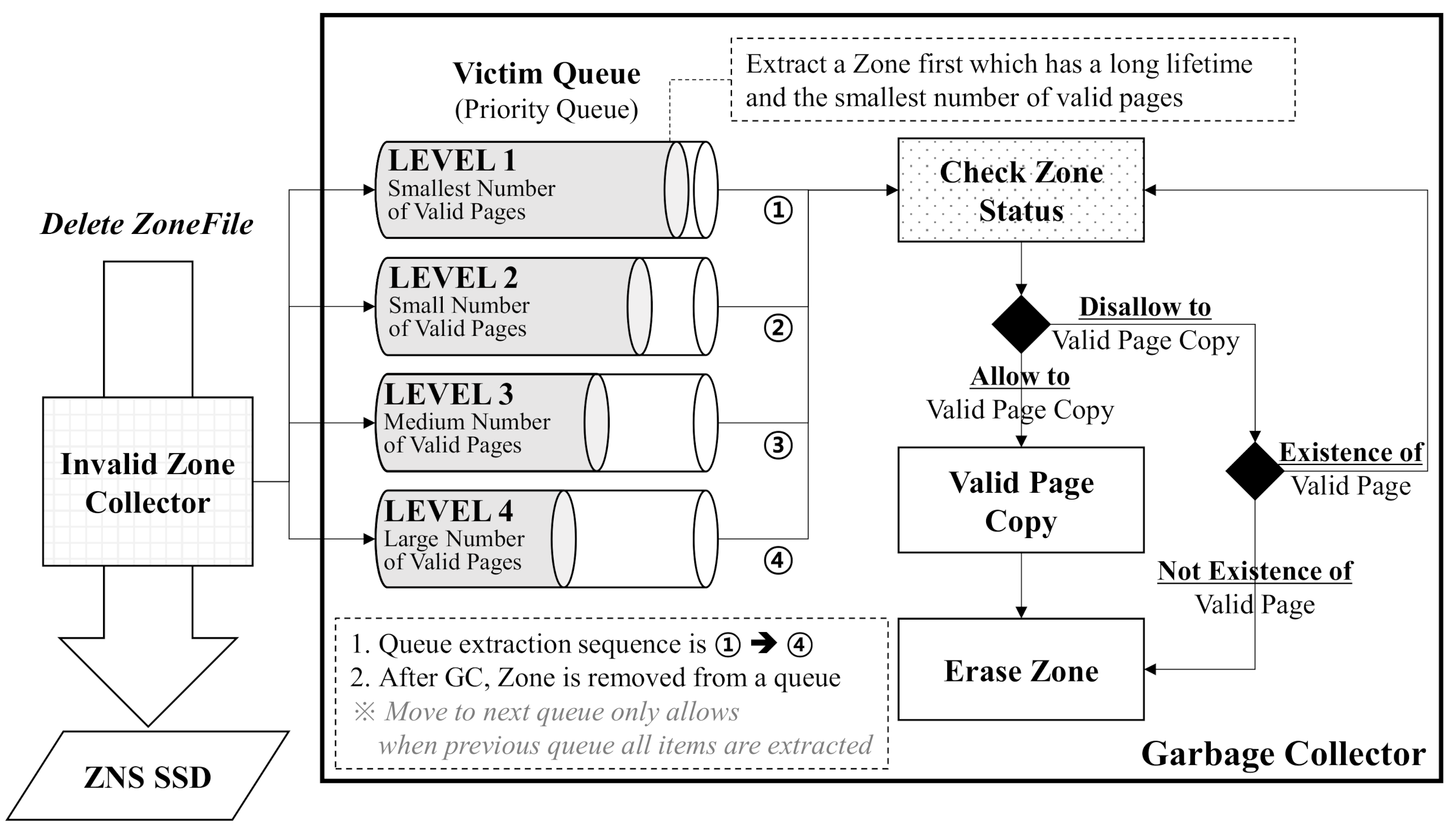
4.2. Garbage Collector for ZNS SSD
4.2.1. Dynamic Victim Selection
4.2.2. Valid Page Copying
5. Implementation
6. Experiments
6.1. Environments
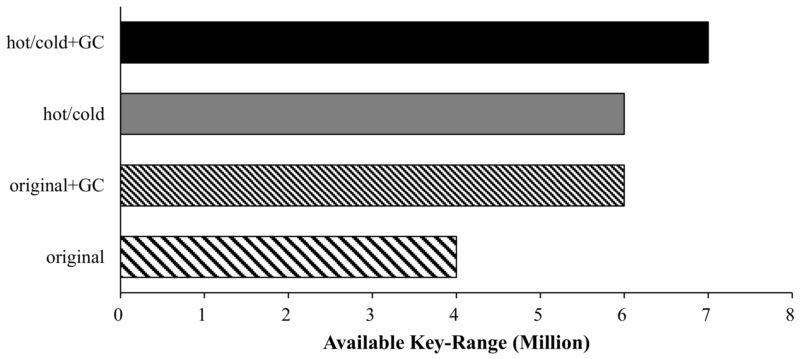
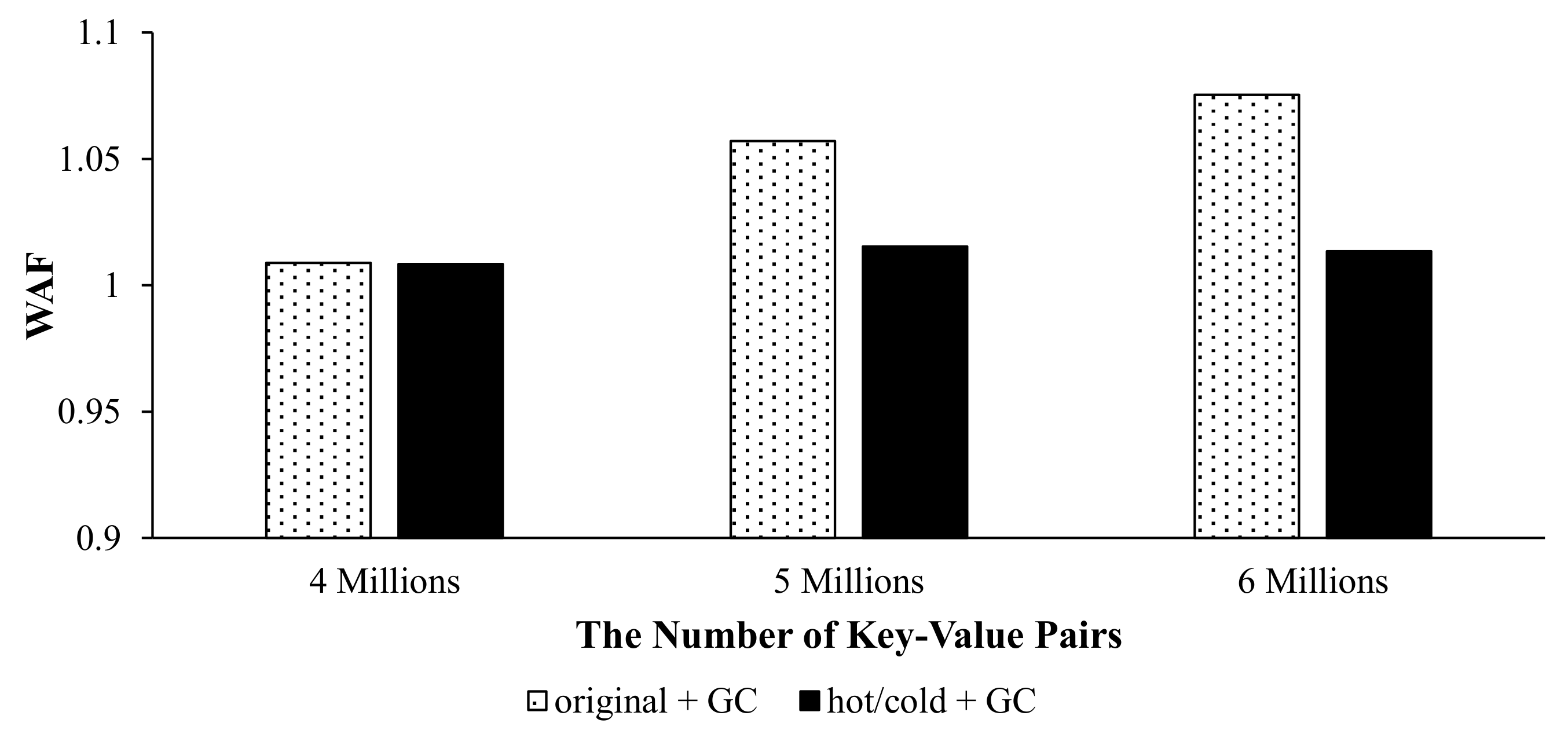
6.2. Analysis of Space Utilization
6.3. I/O Performance
6.4. Effect of the Dynamic Victim Selection
7. Conclusions
Author Contributions
Funding
Conflicts of Interest
References
- Gandhi, S.; Iyer, A.P. P3: Distributed deep graph learning at scale. In Proceedings of the 15th USENIX Symposium on Operating Systems Design and Implementation (OSDI 21), Santa Clara, CA, USA, 14–16 July 2021; pp. 551–568. [Google Scholar]
- Kim, H.; Park, J.H.; Jung, S.H.; Lee, S.W. Optimizing RocksDB for better read throughput in Blockchain systems. In Proceedings of the 23rd International Computer Science and Engineering Conference (ICSEC), Phuket, Thailand, 30 October–1 November 2019; pp. 305–309. [Google Scholar]
- Han, J.; Haihong, E.; Le, G.; Du, J. Survey on NoSQL database. In Proceedings of the 2011 6th International Conference on Pervasive Computing and Applications, Port Elizabeth, South Africa, 26–28 October 2011; pp. 363–366. [Google Scholar]
- Luo, C.; Carey, M.J. LSM-based storage techniques: A survey. VLDB J. 2020, 29, 393–418. [Google Scholar] [CrossRef] [Green Version]
- O’Neil, P.; Cheng, E.; Gawlick, D.; O’Neil, E. The log-structured merge-tree (LSM-tree). Acta Inform. 1996, 33, 351–385. [Google Scholar] [CrossRef]
- Zhong, W.; Chen, C.; Wu, X.; Jiang, S. REMIX: Efficient range query for LSM-trees. In Proceedings of the 19th USENIX Conference on File and Storage Technologies (FAST 21), Santa Clara, CA, USA, 23–25 February 2021; pp. 51–64. [Google Scholar]
- Yang, M.-C.; Chang, Y.-M.; Tsao, C.-W.; Huang, P.-C.; Chang, Y.-H.; Kuo, T.-W. Garbage collection and wear leveling for flash memory: Past and future. In Proceedings of the 2014 International Conference on Smart Computing (SMARTCOMP), Hong Kong, China, 3–5 November 2014; pp. 66–73. [Google Scholar]
- Bjørling, M. From open-channel SSDs to zoned namespaces. In Proceedings of the Linux Storage and Filesystems Conference (Vault 19), USENIX Association, Boston, MA, USA, 26 February 2019. [Google Scholar]
- Choi, G.; Lee, K.; Oh, M.; Choi, J.; Jhin, J.; Oh, Y. A New LSM-style Garbage Collection Scheme for ZNS SSDs. In Proceedings of the 12th USENIX Workshop on Hot Topics in Storage and File Systems (HotStorage 20), Boston, MA, USA, 13–14 July 2020. [Google Scholar]
- Hwang, J. Towards even lower total cost of ownership of data center IT infrastructure. In Proceedings of the NVRAMOS Workshop, Jeju, Korea, 24–26 October 2019. [Google Scholar]
- Yang, F.; Dou, K.; Chen, S.; Hou, M.; Kang, J.-U.; Cho, S. Optimizing NoSQL DB on flash: A Case Study of RocksDB. In Proceedings of the 2015 IEEE 12th Intl Conf on Ubiquitous Intelligence and Computing and 2015 IEEE 12th Intl Conf on Autonomic and Trusted Computing and 2015 IEEE 15th Intl Conf on Scalable Computing and Communications and Its Associated Workshops (UIC-ATC-ScalCom), Beijing, China, 10–14 August 2015; pp. 1062–1069. [Google Scholar]
- Bjørling, M.; Aghayev, A.; Holmberg, H.; Ramesh, A.; Le Moal, D.; Ganger, G.R.; Amvrosiadis, G. ZNS: Avoiding the block interface tax for flash-based SSDs. In Proceedings of the 2021 USENIX Annual Technical Conference (ATC 21), Santa Clara, CA, USA, 14–16 July 2021; pp. 689–703. [Google Scholar]
- WesternDigital. RocksDB. Available online: https://github.com/westerndigitalcorporation/rocksdb (accessed on 23 March 2021).
- WesternDigital. Getting Started with Emulated NVMe ZNS Devices. Available online: https://zonedstorage.io/docs/getting-started/zns-emulation (accessed on 23 March 2021).
- Campello, J. SMR: The next generation of storage technology. In Proceedings of the Storage Development Conference (SDC 15), Santa Clara, CA, USA, 21 September 2015. [Google Scholar]
- Bjørling, M. Open-channel solid state drives. In Proceedings of the 2015 Linux Storage and Filesystems Conference (Vault 15), Boston, MA, USA, 12 March 2015. [Google Scholar]
- Manzanares, A.; Watkins, N.; Guyot, C.; LeMoal, D.; Maltzahn, C.; Bandic, Z. ZEA, A data management approach for SMR. In Proceedings of the 8th USENIX Workshop on Hot Topics in Storage and File Systems (HotStorage 16), Denver, CO, USA, 20–21 June 2016. [Google Scholar]
- Wu, F.; Yang, M.-C.; Fan, Z.; Zhang, B.; Ge, X.; Du, D.H. Evaluating host aware SMR drives. In Proceedings of the 8th USENIX Workshop on Hot Topics in Storage and File Systems (HotStorage 16), Denver, CO, USA, 21 June 2016. [Google Scholar]
- Zhang, Y.; Arulraj, L.P.; Arpaci-Dusseau, A.C.; Arpaci-Dusseau, R.H. De-indirection for flash-based SSDs with Nameless Writes. In Proceedings of the 10th USENIX Conference on File and Storage Technologies (FAST 12), San Jose, CA, USA, 14–17 February 2012. [Google Scholar]
- Cao, Z.; Dong, S.; Vemuri, S.; Du, D.H. Characterizing, modeling, and benchmarking RocksDB key-value workloads at Facebook. In Proceedings of the 18th USENIX Conference on File and Storage Technologies (FAST 20), Santa Clara, CA, USA, 25–27 February 2020; pp. 209–223. [Google Scholar]
- WesternDigital. Libzbd. Available online: https://github.com/westerndigitalcorporation/libzbd (accessed on 22 March 2021).
- Holmberg, H. ZenFS, Zones and RocksDB—Who likes to take out the garbage anyway? In Proceedings of the Storage Development Conference (SDC 20), Santa Clara, CA, USA, 23 September 2020. [Google Scholar]
- WesternDigital. ZenFS. Available online: https://github.com/westerndigitalcorporation/zenfs (accessed on 7 November 2021).
- NVMExpress. TP 4053a Zoned Namespace. Available online: https://nvmexpress.org/wp-content/uploads/NVM-Express-1.4-Ratified-TPs_09022021.zip (accessed on 10 November 2021).
- Bjørling, M.; Gonzalez, J.; Bonnet, P. Lightnvm: The Linux open-channel {SSD} subsystem. In Proceedings of the 15th USENIX Conference on File and Storage Technologies (FAST 17), Santa Clara, CA, USA, 27 February–2 March 2017; pp. 359–374. [Google Scholar]


| Component | Specification |
|---|---|
| Central Processing Unit | Intel Xeon CPU E5-2620v4 @ 2.1 GHz |
| Memory (CPU) | Samsung 32 GB PC17000/ECC/REG 4 |
| Storage | Intel® SSD DC P4500 Series (1.0 TB, 2.5in PCIe 3.1x4, 3D1, TLC) |
| Operating System (Kernel) | Ubuntu 18.04.2 LTS (Linux Kernel 5.3) |
| Configuration | Value |
|---|---|
| Number of Cores | 32 |
| Memory Size | 32 GB |
| Storage | Emulated ZNS SSD 8 GiB (QEMU NVMe Ctrl) |
| OS (Kernel) | Debian Bullseye (Linux Kernel 5.10) |
| Component | Specification |
|---|---|
| Zone Model | Host-Managed |
| Capacity | 8 GiB |
| Sector Size | 512 bytes |
| Number of Zones | 512 |
| Zone Size | 16 MiB |
| Max. Open Zones | 384 |
| Max. Active Zones | 384 |
| Configuration | Value |
|---|---|
| Key Size | 16 bytes |
| Value Size | 800 bytes |
| Write Buffer Size | 16 MiB |
| Max. SST File Size | 16 MiB |
| Max. Background Thread | 16 |
| Item | Lifetime-Based Zone Allocation | Garbage Collection |
|---|---|---|
| Original | X | X |
| Original + GC | X | O |
| Hot/Cold | O | X |
| Hot/Cold + GC | O | O |
Publisher’s Note: MDPI stays neutral with regard to jurisdictional claims in published maps and institutional affiliations. |
© 2021 by the authors. Licensee MDPI, Basel, Switzerland. This article is an open access article distributed under the terms and conditions of the Creative Commons Attribution (CC BY) license (https://creativecommons.org/licenses/by/4.0/).
Share and Cite
Oh, G.; Yang, J.; Ahn, S. Efficient Key-Value Data Placement for ZNS SSD. Appl. Sci. 2021, 11, 11842. https://doi.org/10.3390/app112411842
Oh G, Yang J, Ahn S. Efficient Key-Value Data Placement for ZNS SSD. Applied Sciences. 2021; 11(24):11842. https://doi.org/10.3390/app112411842
Chicago/Turabian StyleOh, Gijun, Junseok Yang, and Sungyong Ahn. 2021. "Efficient Key-Value Data Placement for ZNS SSD" Applied Sciences 11, no. 24: 11842. https://doi.org/10.3390/app112411842
APA StyleOh, G., Yang, J., & Ahn, S. (2021). Efficient Key-Value Data Placement for ZNS SSD. Applied Sciences, 11(24), 11842. https://doi.org/10.3390/app112411842