
Surface Treatment of Ultra-High Molecular Weight Polyethylene (UHMWPE) by Cold Atmospheric Plasma (CAP) for Biocompatibility Enhancement


Abstract
:1. Introduction
2. Materials and Methods
3. Results and Discussion
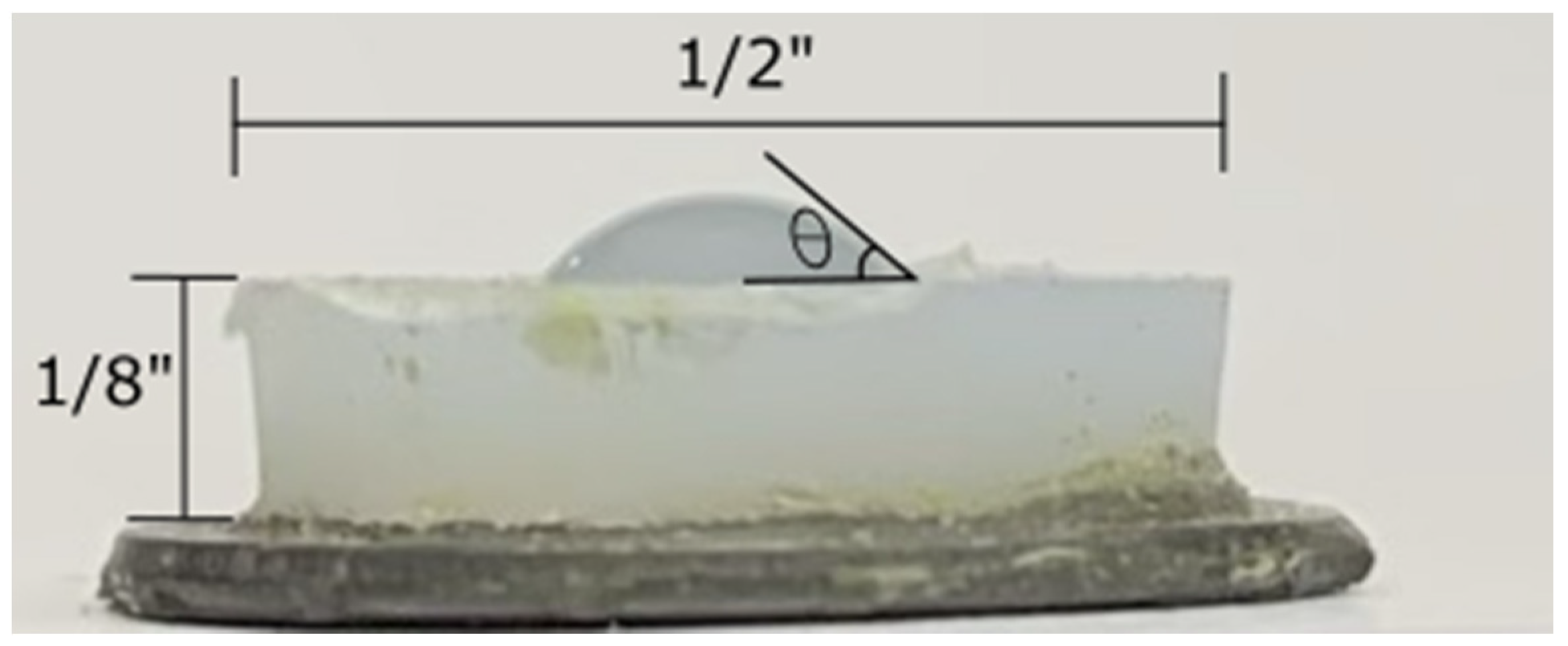
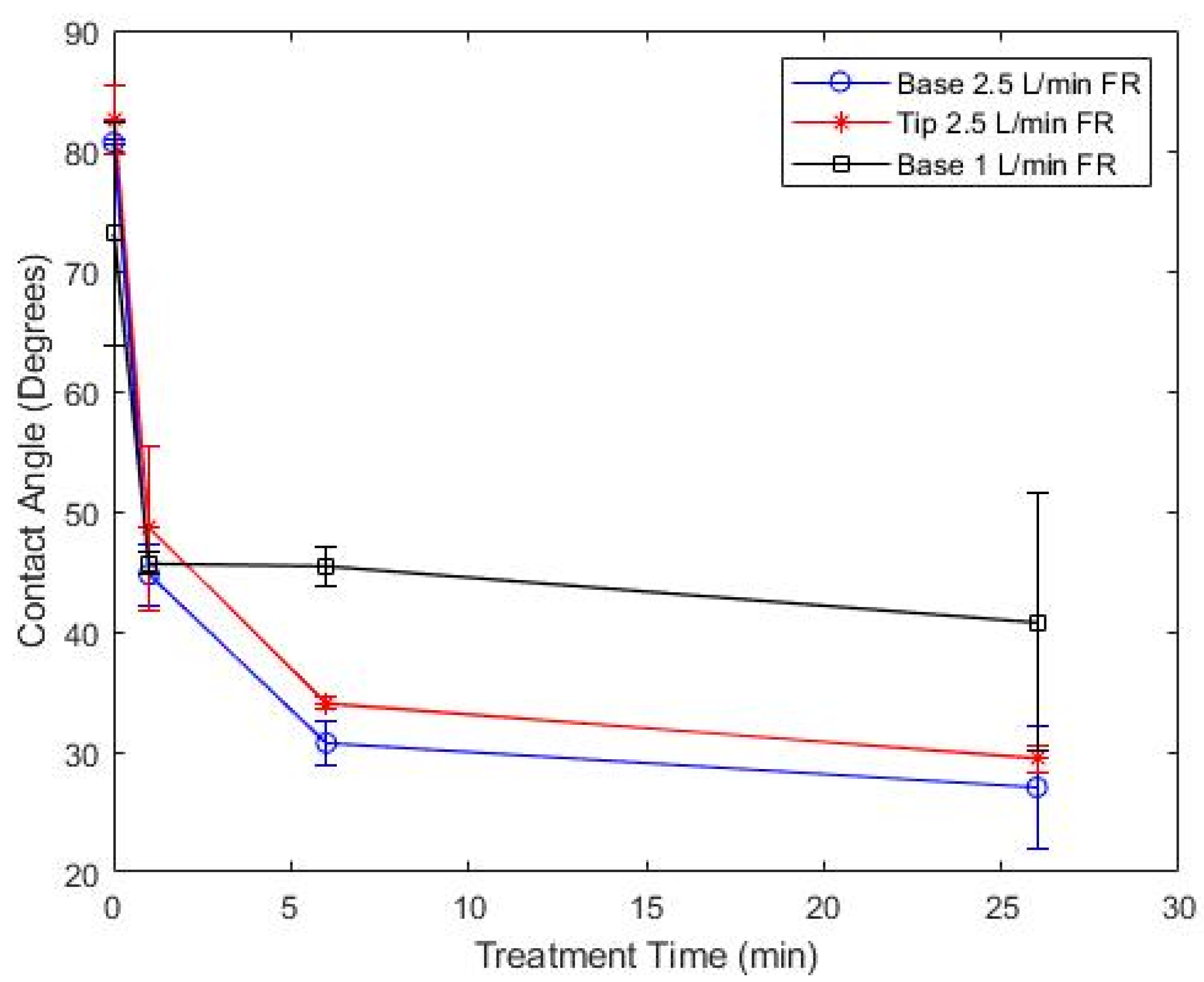
3.1. Contact Angle
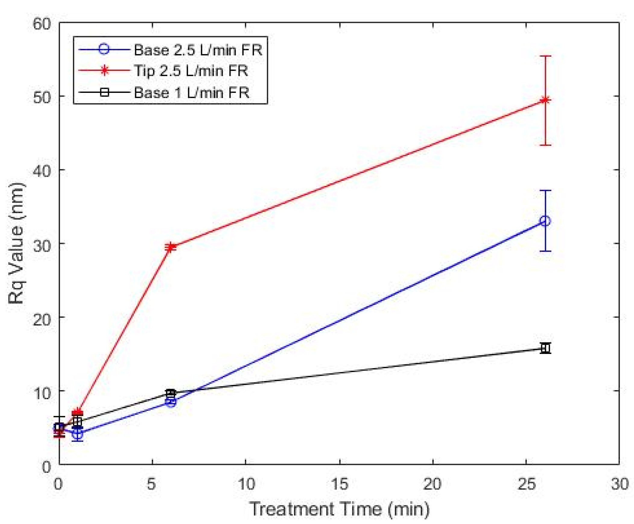
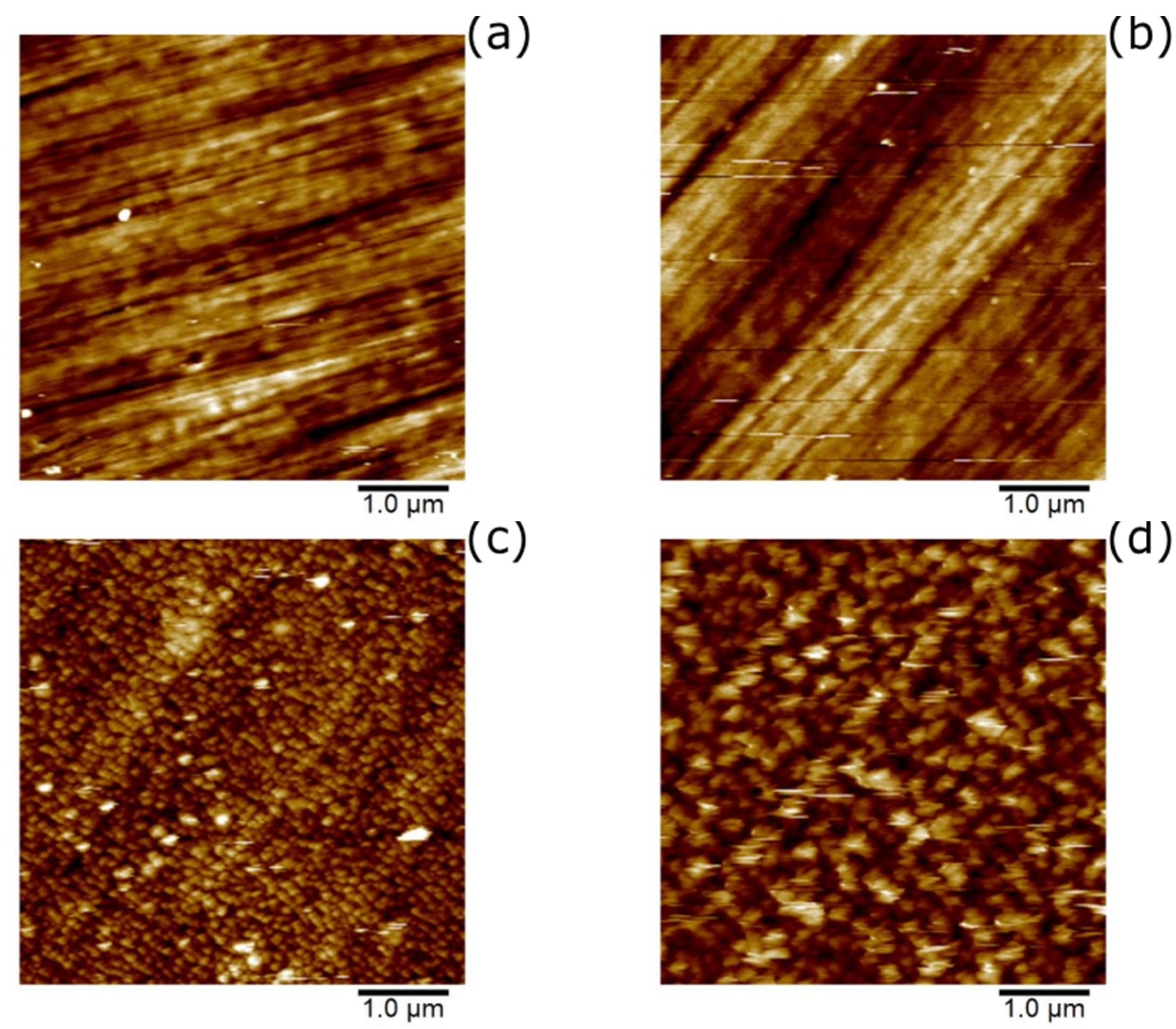
3.2. Roughness
3.3. Hardness
4. Conclusions
Author Contributions
Funding
Institutional Review Board Statement
Informed Consent Statement
Data Availability Statement
Acknowledgments
Conflicts of Interest
References
- Turicek, J.; Ratts, N.; Kaltchev, M.; Masoud, N. Characterization of Helium CAP Tubular Source and Investigation of UHMWPE Surface Treatment. In Proceedings of the 73rd Annual Gaseous Electronics Virtual Conference, Princeton, NJ, USA, 5–9 October 2020. [Google Scholar]
- Sobieraj, M.; Rimnac, C. Ultra High Molecular Weight Polyethylene: Mechanics, Morphology, and Clinical Behavior. J. Mech. Behav. Biomed. Mater. 2009, 2, 433–443. [Google Scholar] [CrossRef] [PubMed] [Green Version]
- Bracco, P.; Bellare, A.; Bistolfi, A.; Affatato, S. Ultra-High Molecular Weight Polyethylene: Influence of the Chemical, Physical and Mechanical Properties on the Wear Behavior. A Review. Materials 2017, 10, 791. [Google Scholar] [CrossRef]
- Preedy, E.C.; Brousseau, E.; Evans, S.L.; Perni, S.; Prokopovich, P. Adhesive forces and surface properties of cold gas plasma treated UHMWPE. Colloids Surf. A Physicochem. Eng. Asp. 2014, 460, 83–89. [Google Scholar] [CrossRef] [Green Version]
- Anonymous. Meeting the Joint Replacement Challenge with UHMWPE. MDDI Online, 1 March 2005. Available online: https://www.mddionline.com/meeting-joint-replacement-challenge-uhmwpe(accessed on 24 April 2020).
- Bykova, I.; Weinhardt, V.; Kashkarova, A.; Lebedev, S.; Baumbach, T.; Pichugin, V.; Zaitsev, K.; Khlusov, I. Physical properties and biocompatibility of UHMWPE-derived materials modified by synchrotron radiation. J. Mater. Sci. Mater. Med. 2014, 25, 1843–1852. [Google Scholar] [CrossRef] [PubMed] [Green Version]
- Patil, N.A.; Njuguna, J.; Kandasubramanian, B. UHMWPE for biomedical applications: Performance and functionalization. Eur. Polym. J. 2020, 125, 109529. [Google Scholar] [CrossRef]
- Visco, A.; Scolaro, C.; Terracciano, T.; Montanini, R.; Quattrocchi, A.; Torrisi, L.; Restuccia, N. Static and dynamic characterization of biomedical polyethylene laser welding using biocompatible nano-particles. EPJ Web Conf. 2018, 167, 05009. [Google Scholar] [CrossRef] [Green Version]
- Visco, A.; Scolaro, C.; Quattrocchi, A.; Montanini, R. Response to fatigue stress of biomedical grade polyethylene joints welded by a diode laser. J. Mech. Behav. Biomed. Mater. 2018, 86, 390–396. [Google Scholar] [CrossRef]
- Baena, J.C.; Wu, J.; Peng, Z. Wear Performance of UHMWPE and Reinforced UHMWPE Composites in Arthroplasty Applications: A Review. Lubricants 2015, 3, 413–436. [Google Scholar] [CrossRef] [Green Version]
- Marcondes, A.R.; Ueda, M.; Kostov, K.G.; Beloto, A.F.; Leite, N.F.; Gomes, G.F.; Lepienski, C.M. Improvements of ultra-high molecular weight polyethylene mechanical properties by nitrogen plasma immersion ion implantation. Braz. J. Phys. 2004, 34, 1667–1672. [Google Scholar] [CrossRef] [Green Version]
- Van Vrekhem, S.; Vloebergh, K.; Asadian, M.; Vercruysse, C.; Declercq, H.; Van Tongel, A.; de Wilde, L.; de Geyter, N.; Morent, R. Improving the surface properties of an UHMWPE shoulder implant with an atmospheric pressure plasma jet. Sci. Rep. 2018, 8, 4720. [Google Scholar] [CrossRef]
- Nair, K.; Whiteside, B.; Grant, C.; Patel, R.; Tuinea-Bobe, C.; Norris, K.; Paradkar, A. Investigation of Plasma Treatment on Micro-Injection Moulded Microneedle for Drug Delivery. Pharmaceutics 2015, 7, 471–485. [Google Scholar] [CrossRef] [Green Version]
- Qureshi, A.; Shah, S.; Pelagade, S.; Singh, N.L.; Mukherjee, S.; Tripathi, A.; Despande, U.P.; Shripathi, T. Surface modification of polycarbonate by plasma treatment. J. Phys. Conf. Ser. 2010, 208, 012108. [Google Scholar] [CrossRef]
- Mitsubishi Chemical Advanced Materials TIVAR® 1000 UHMW-PE, (Natural & Colors except Black) UHMW-PE (ASTM Product Data Sheet). Available online: http://qepp.matweb.com/search/DataSheet.aspx?Bassnum=P1SMP00&ckck=1 (accessed on 10 June 2020).
- Al-Malik, H.L.R. Adhesive and Tribological Behaviour of Cold Atmospheric Plasma-Treated Polymer Surfaces. Ph.D. Thesis, Szent Istvan University, Budapest, Hungary, 2018; p. 115. [Google Scholar]
- Schuster, J.M.; Schvezov, C.E.; Rosenberger, M.R. Influence of Experimental Variables on the Measure of Contact Angle in Metals Using the Sessile Drop Method. Procedia Mater. Sci. 2015, 8, 742–751. [Google Scholar] [CrossRef]
- Affatato, S.; Ruggiero, A.; Merola, M. Advanced biomaterials in hip joint arthroplasty. A review on polymer and ceramics composites as alternative bearings. Compos. Part B Eng. 2015, 83, 276–283. [Google Scholar] [CrossRef]
- Kumar, N.N.; Yap, S.L.; Bt Samsudin, F.N.D.; Khan, M.Z.; Pattela Srinivasa, R.S. Effect of Argon Plasma Treatment on Tribological Properties of UHMWPE/MWCNT Nanocomposites. Polymers 2016, 8, 295. [Google Scholar] [CrossRef] [Green Version]
- Rex Gauge Company, Inc. Operating Instructions. Available online: https://www.durometer.com/wp-content/uploads/REXOpInstrucv1214r.pdf (accessed on 24 April 2020).
- Nikiforov, A.Y.; Sarani, A.; Leys, C. The influence of water vapor content on electrical and spectral properties of an atmospheric pressure plasma jet. Plasma Sources Sci. Technol. 2011, 20, 015014. [Google Scholar] [CrossRef]
- Gott, R.P.; Xu, K.G. OH Production and Jet Length of an Atmospheric-Pressure Plasma Jet for Soft and Biomaterial Treatment. IEEE Trans. Plasma Sci. 2019, 47, 4988–4999. [Google Scholar] [CrossRef]
- Kasalkova, N.S.; Slepicka, P.; Kolska, Z.; Svorcik, V. Wettability and Other Surface Properties of Modified Polymers. Wetting Wettability 2015, 12, 323–356. [Google Scholar] [CrossRef] [Green Version]
- Mandolfino, C.; Lertora, E.; Gambaro, C. Effect of Cold Plasma Treatment on Surface Roughness and Bonding Strength of Polymeric Substrates. Key Eng. Mater. 2014. [Google Scholar] [CrossRef]
- Macgregor, M.; Vasilev, K. Perspective on Plasma Polymers for Applied Biomaterials Nanoengineering and the Recent Rise of Oxazolines. Materials 2019, 12, 191. [Google Scholar] [CrossRef] [PubMed] [Green Version]
- Puliyalil, H.; Cvelbar, U. Selective Plasma Etching of Polymeric Substrates for Advanced Applications. Nanomaterials 2016, 6, 108. [Google Scholar] [CrossRef] [PubMed] [Green Version]
- Ohkubo, Y.; Shibahara, M.; Nagatani, A.; Honda, K.; Endo, K.; Yamamura, K. Comparison between adhesion properties of adhesive bonding and adhesive-free adhesion for heat-assisted plasma-treated polytetrafluoroethylene (PTFE). J. Adhes. 2018, 96, 776–796. [Google Scholar] [CrossRef] [Green Version]
- Neděla, O.; Slepička, P.; Švorčík, V. Surface Modification of Polymer Substrates for Biomedical Applications. Materials 2017, 10, 1115. [Google Scholar] [CrossRef]
- Ghosh, S.; Abanteriba, S. Status of surface modification techniques for artificial hip implants. Sci. Technol. Adv. Mater. 2016, 17, 715–735. [Google Scholar] [CrossRef] [PubMed] [Green Version]

| Flow Rate [L/min] | Position on Plume | Measurements Performed |
|---|---|---|
| 1 | Base | AFM, Contact Angle |
| Hardness | ||
| 2.5 | Base | AFM, Contact Angle |
| Hardness | ||
| Tip | AFM, Contact Angle | |
| Hardness |
| Treatment Time (min) | Hardness (Shore-D) [duro] | ||
|---|---|---|---|
| Base FR:1 L/min | Base FR: 2.5 L/min | Tip FR: 2.5 L/min | |
| 0 | 68.7 | 68.7 | 68.7 |
| 1 | 70.5 | 69 | 70 |
| 6 | 70.5 | 70 | 70 |
| 26 | 70.5 | 69 | 69 |
| Treatment Time (min) | Hardness (Shore-D) [duro] | ||
|---|---|---|---|
| Base FR:1 L/min | Base FR: 2.5 L/min | Tip FR: 2.5 L/min | |
| 0 | 64.7 | 64.7 | 64.7 |
| 1 | 67 | 64 | 65 |
| 6 | 67.5 | 65 | 66 |
| 26 | 67 | 65 | 67 |
Publisher’s Note: MDPI stays neutral with regard to jurisdictional claims in published maps and institutional affiliations. |
© 2021 by the authors. Licensee MDPI, Basel, Switzerland. This article is an open access article distributed under the terms and conditions of the Creative Commons Attribution (CC BY) license (http://creativecommons.org/licenses/by/4.0/).
Share and Cite
Turicek, J.; Ratts, N.; Kaltchev, M.; Masoud, N. Surface Treatment of Ultra-High Molecular Weight Polyethylene (UHMWPE) by Cold Atmospheric Plasma (CAP) for Biocompatibility Enhancement. Appl. Sci. 2021, 11, 1703. https://doi.org/10.3390/app11041703
Turicek J, Ratts N, Kaltchev M, Masoud N. Surface Treatment of Ultra-High Molecular Weight Polyethylene (UHMWPE) by Cold Atmospheric Plasma (CAP) for Biocompatibility Enhancement. Applied Sciences. 2021; 11(4):1703. https://doi.org/10.3390/app11041703
Chicago/Turabian StyleTuricek, Jack, Nicole Ratts, Matey Kaltchev, and Nazieh Masoud. 2021. "Surface Treatment of Ultra-High Molecular Weight Polyethylene (UHMWPE) by Cold Atmospheric Plasma (CAP) for Biocompatibility Enhancement" Applied Sciences 11, no. 4: 1703. https://doi.org/10.3390/app11041703