
Stress and Fatigue Analysis of Picking Device Gears for a 2.6 kW Automatic Pepper Transplanter

 ,
,  ,
,  ,
, 
 and
and 
Abstract
:1. Introduction
2. Materials and Methods
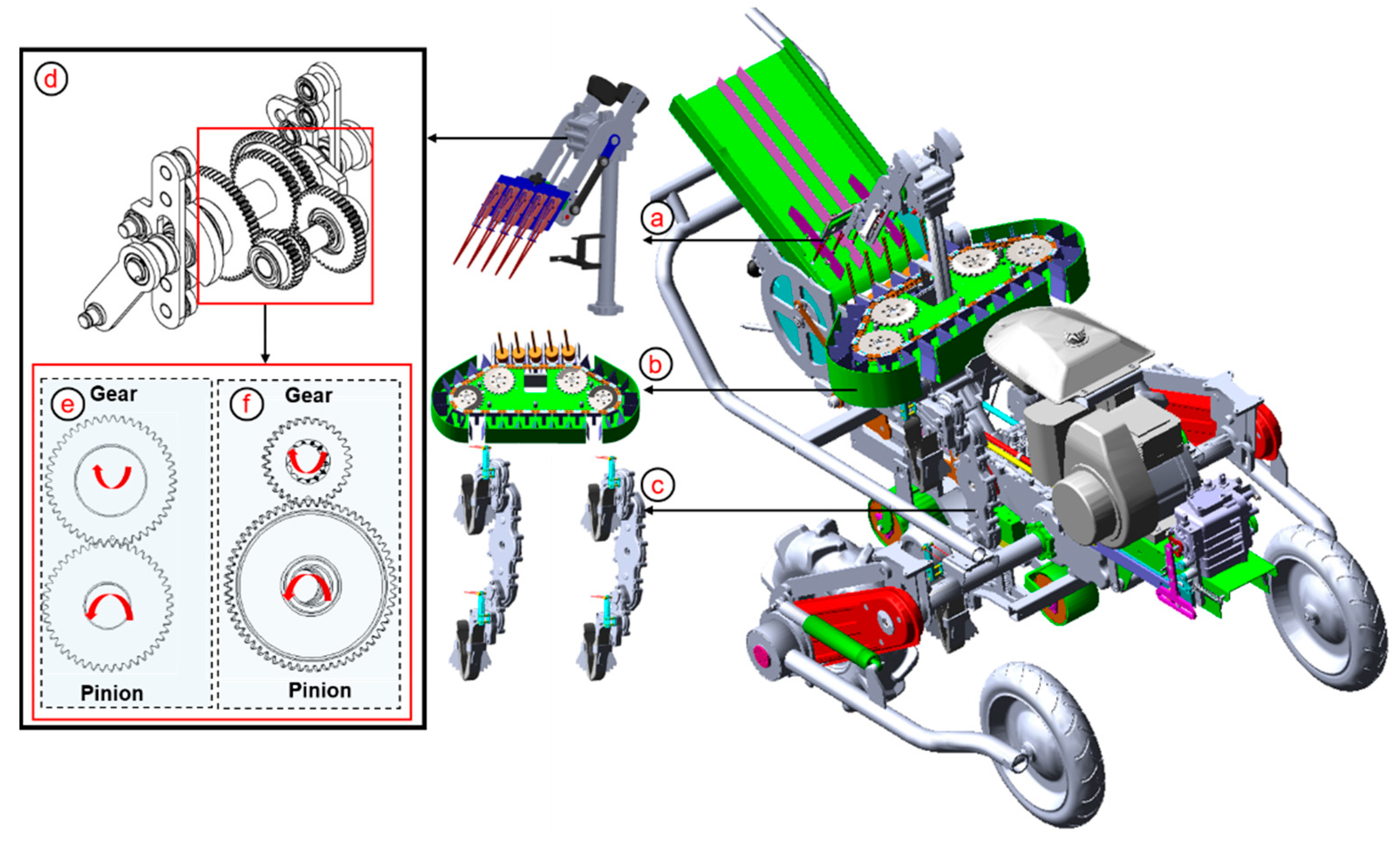
2.1. Structure of the Automatic Pepper Transplanter under Development
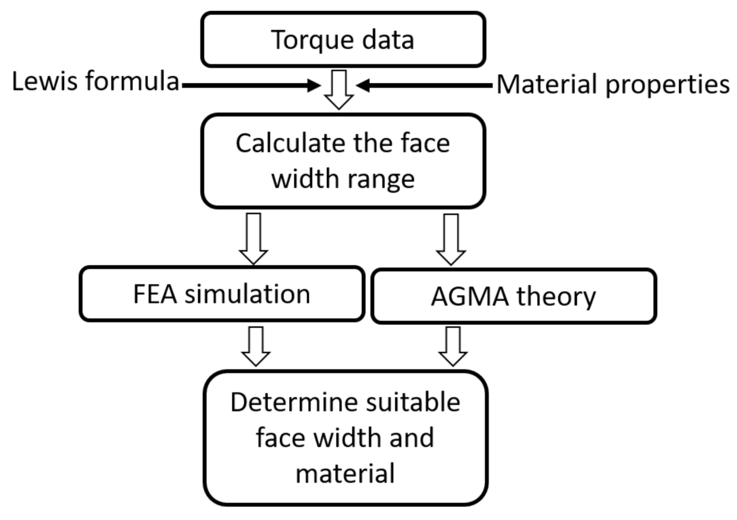
2.2. Determination of Suitable Face Width and Material
2.2.1. Selection of Appropriate Face Width Range
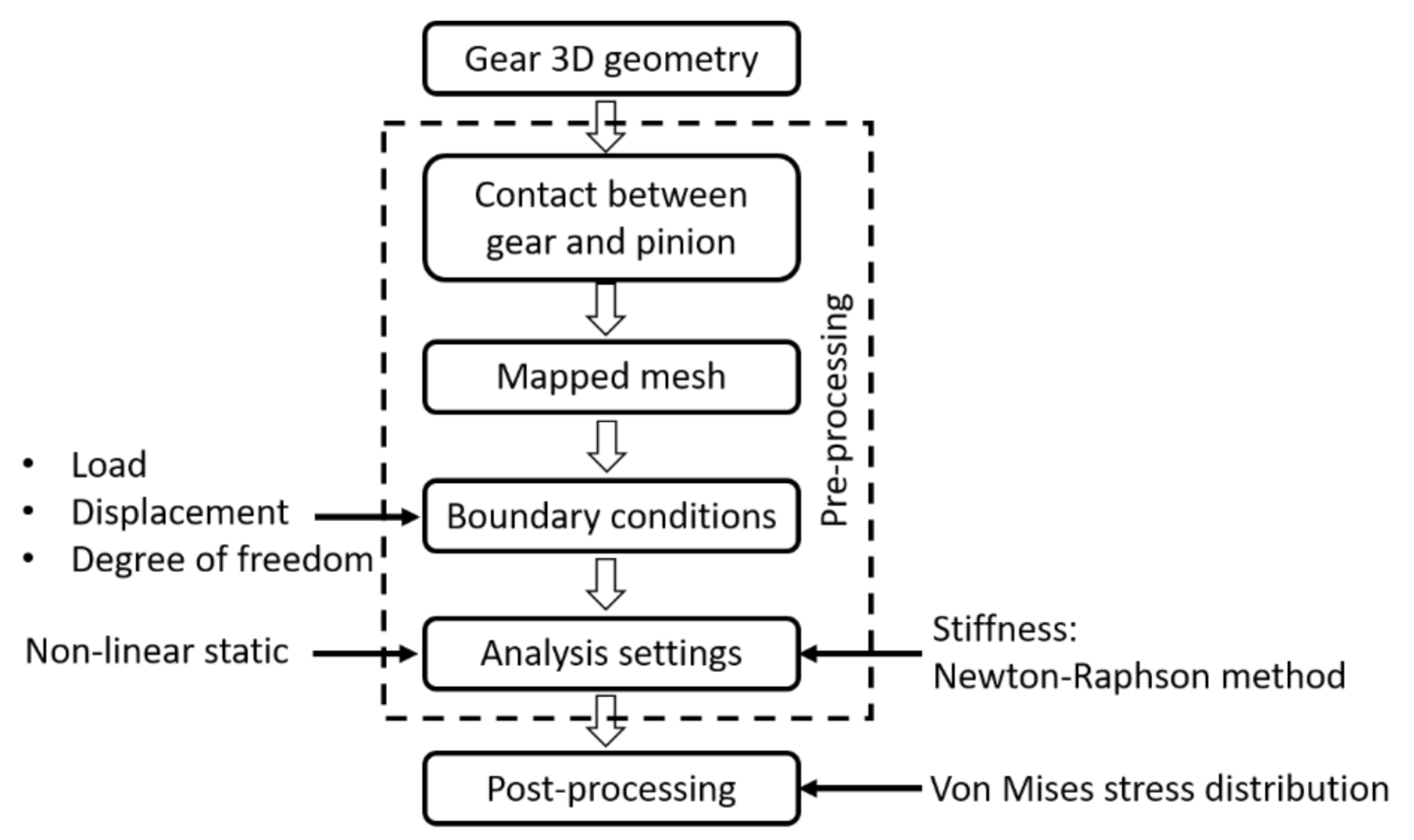
2.2.2. Gear Contact Stress Analysis by FEA Simulation
2.2.3. Gear Contact Stress Analysis with AGMA Theory
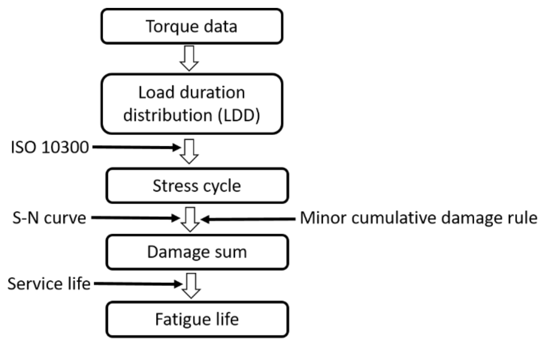
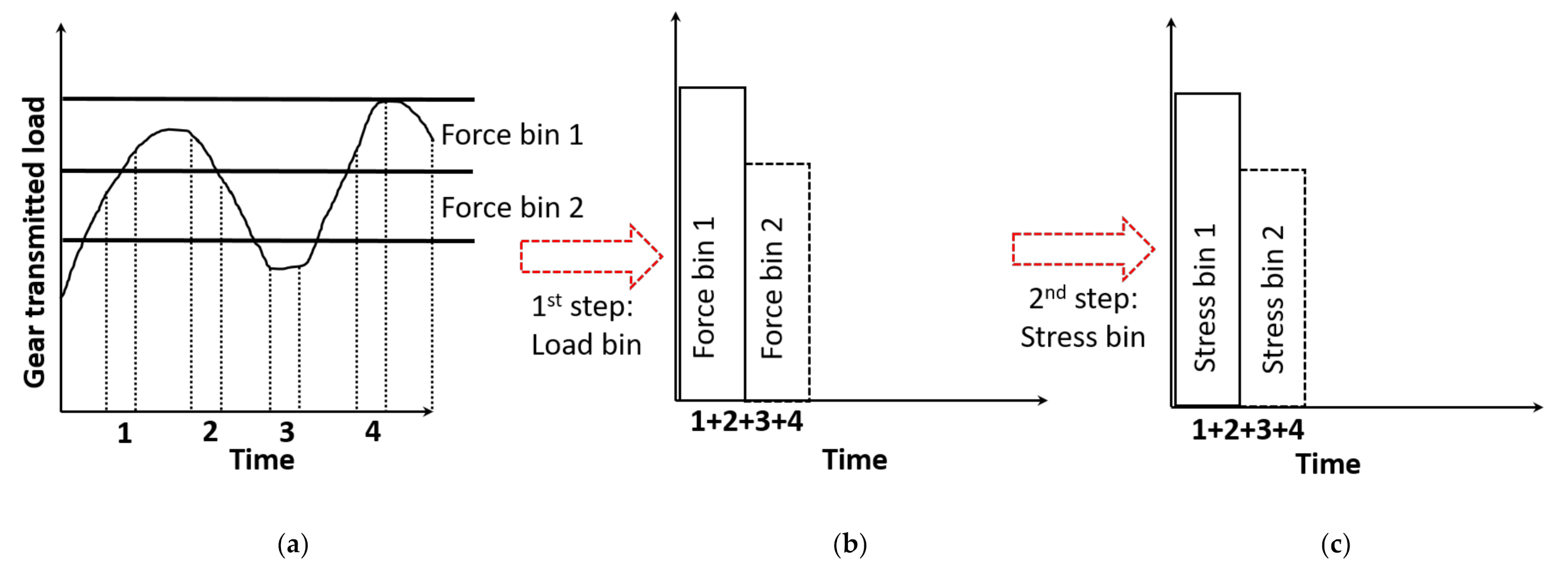
2.3. Fatigue Life Prediction
2.4. Experimental Setup
3. Results and Discussion
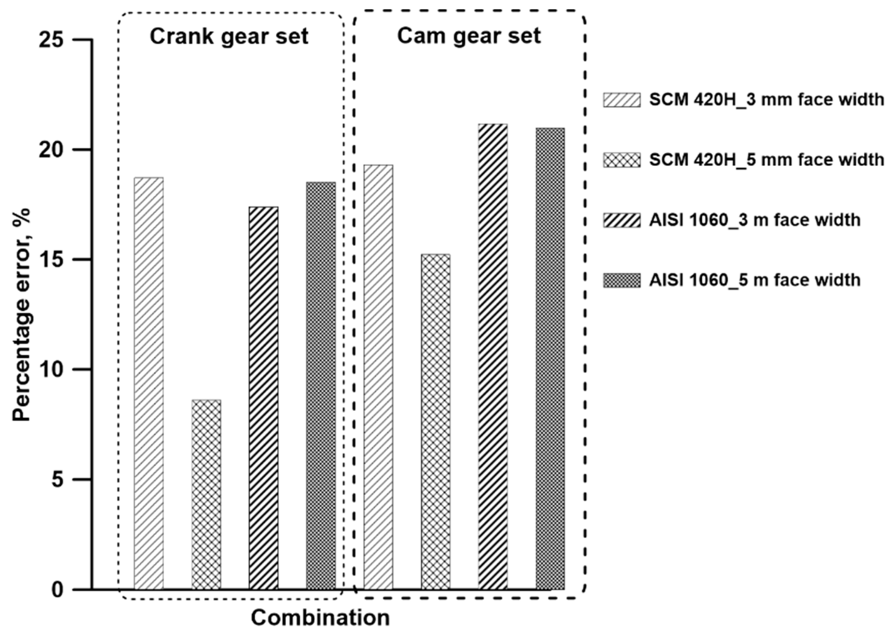
3.1. Appropriate Gear Material and Face Width
3.2. Gear Mechanism Fatigue Life
4. Conclusions
Author Contributions
Funding
Institutional Review Board Statement
Informed Consent Statement
Data Availability Statement
Conflicts of Interest
References
- Surh, Y.J.; Lee, E.; Lee, J.M. Chemoprotective properties of some pungent ingredients present in red pepper and ginger. Mutat. Res. Mol. Mech. Mutagen. 1998, 402, 259–267. [Google Scholar] [CrossRef]
- Maia, A.A.D.; de Morais, L.C. Kinetic parameters of red pepper waste as biomass to solid biofuel. Bioresour. Technol. 2016, 204, 157–163. [Google Scholar] [CrossRef] [PubMed] [Green Version]
- Islam, M.N.; Iqbal, M.Z.; Ali, M.; Chowdhury, M.; Kabir, M.S.N.; Park, T.; Kim, Y.J.; Chung, S.O. Kinematic analysis of a clamp-type picking device for an automatic pepper transplanter. Agriculture 2020, 10, 0627. [Google Scholar] [CrossRef]
- Dihingia, P.C.; Kumar, G.V.P.; Sarma, P.K. Development of a hopper-type planting device for a walk-behind hand-tractor-powered vegetable transplanter. J. Biosyst. Eng. 2016, 41, 21–33. [Google Scholar] [CrossRef] [Green Version]
- Paraforos, D.S.; Griepentrog, H.W.; Vougioukas, S.G. Methodology for designing accelerated structural durability tests on agricultural machinery. Biosyst. Eng. 2016, 149, 24–37. [Google Scholar] [CrossRef]
- Socie, D.; Pompetzki, M. Modeling variability in service loading spectra. J. ASTM Int. 2004, 1, 11561. [Google Scholar] [CrossRef]
- Perozzi, D.; Mattetti, M.; Molari, G.; Sereni, E. Methodology to analyse farm tractor idling time. Biosyst. Eng. 2016, 148, 81–89. [Google Scholar] [CrossRef]
- Margolin, L.G. Damage and failure in a statistical crack model. Appl. Sci. 2020, 10, 8700. [Google Scholar] [CrossRef]
- Lee, Y.S.; Ali, M.; Islam, M.N.; Rasool, K.; Jang, B.E.; Kabir, M.S.N.; Kang, T.K.; Chung, S.O. Theoretical analysis of bending stresses to design a sprocket for transportation part of a chinese cabbage collector. J. Biosyst. Eng. 2020, 45, 85–93. [Google Scholar] [CrossRef]
- Prabhakaran, S.; Ds, B. Stress analysis and effect of misalignment in spur gear stress analysis and effect of misalignment in spur gear. Int. J. Appl. Eng. Res. 2014, 9, 13061–13071. [Google Scholar]
- Li, S. Effect of addendum on contact strength, bending strength and basic performance parameters of a pair of spur gears. Mech. Mach. Theory 2008, 43, 1557–1584. [Google Scholar] [CrossRef]
- Pedrero, J.I.; Pleguezuelos, M.; Muñoz, M. Critical stress and load conditions for pitting calculations of involute spur and helical gear teeth. Mech. Mach. Theory 2011, 46, 425–437. [Google Scholar] [CrossRef]
- Zhang, Y.; Fang, Z. Analysis of tooth contact and load distribution of helical gears with crossed axes. Mech. Mach. Theory 1999, 34, 41–57. [Google Scholar] [CrossRef]
- Arafa, M.H.; Megahed, M.M. Evaluation of spur gear mesh compliance using the finite element method. Proc. Inst. Mech. Eng. Part C J. Mech. Eng. Sci. 1999, 213, 569–579. [Google Scholar] [CrossRef]
- Pimsarn, M.; Kazerounian, K. Efficient evaluation of spur gear tooth mesh load using pseudo-interference stiffness estimation method. Mech. Mach. Theory 2002, 37, 769–786. [Google Scholar] [CrossRef]
- Hwang, S.C.; Lee, J.H.; Lee, D.H.; Han, S.H.; Lee, K.H. Contact stress analysis for a pair of mating gears. Math. Comput. Model. 2013, 57, 40–49. [Google Scholar] [CrossRef]
- Park, S.; Kim, S.; Choi, J.H. Gear fault diagnosis using transmission error and ensemble empirical mode decomposition. Mech. Syst. Signal Process. 2018, 108, 58–72. [Google Scholar] [CrossRef]
- Kim, W.S.; Kim, Y.J.; Baek, S.M.; Moon, S.P.; Lee, N.G.; Kim, Y.S.; Park, S.U.; Choi, Y.; Kim, Y.K.; Choi, I.S. Fatigue life simulation of tractor spiral bevel gear according to major agricultural operations. Appl. Sci. 2020, 10, 8898. [Google Scholar] [CrossRef]
- Berger, C.; Eulitz, K.-G.; Heuler, P.; Kotte, K.L.; Naundorf, H.; Schuetz, W.; Sonsino, C.; Wimmer, A.; Zenner, H. Betriebsfestigkeit in Germany—An overview. Int. J. Fatigue 2002, 24, 603–625. [Google Scholar] [CrossRef]
- Kloth, W.; Stroppel, T. Kräfte, Beanspruchungen und Sicherheiten in den Landmachinen. Z Ver. Dtsch. Ing., 1936, 80, 85–92. [Google Scholar]
- Harral, B.B. The application of a statistical fatigue life prediction method to agricultural equipment. Int. J. Fatigue 1987, 9, 115–118. [Google Scholar] [CrossRef]
- Kim, J.H.; Kim, K.U.; Wu, Y.G. Analysis of transmission load of agricultural tractors. J. Terramechanics 2000, 37, 113–125. [Google Scholar] [CrossRef]
- Graham, J.A.; Berns, D.K.; Olberts, D.R. Cumulative damage used to analyze tractor final drives. Trans. ASAE 1962, 5, 139–146. [Google Scholar] [CrossRef]
- Kim, Y.J.; Chung, S.O.; Choi, C.H. Effects of gear selection of an agricultural tractor on transmission and PTO load during rotary tillage. Soil Tillage Res. 2013, 134, 90–96. [Google Scholar] [CrossRef]
- Lee, D.H.; Kim, Y.J.; Chung, S.O.; Choi, C.H.; Lee, K.H.; Shin, B.S. Analysis of the PTO load of a 75 kW agricultural tractor during rotary tillage and baler operation in Korean upland fields. J. Terramechanics 2015, 60, 75–83. [Google Scholar] [CrossRef]
- Kim, J.H.; Kim, K.U.; Choi, C.W.; Wu, Y.G. Severeness of transmission loads of agricultural tractors. J. Biosyst. Eng. 1998, 23, 417–426. [Google Scholar]
- Mattetti, M.; Molari, G.; Sereni, E. Damage evaluation of driving events for agricultural tractors. Comput. Electron. Agric. 2017, 135, 328–337. [Google Scholar] [CrossRef]
- Bai, J.; Wu, X.; Gao, F.; Li, H. Analysis of powertrain loading dynamic characteristics and the effects on fatigue damage. Appl. Sci. 2017, 7, 1027. [Google Scholar] [CrossRef] [Green Version]
- Al-Tubi, I.S.; Long, H.; Zhang, J.; Shaw, B. Experimental and analytical study of gear micropitting initiation and propagation under varying loading conditions. Wear 2015, 328–329, 8–16. [Google Scholar] [CrossRef] [Green Version]
- Chen, Y.C.; Tsay, C.B. Stress analysis of a helical gear set with localized bearing contact. Finite Elem. Anal. Des. 2002, 38, 707–723. [Google Scholar] [CrossRef]
- Litvin, F.L.; Lian, Q.; Kapelevich, A.L. Asymmetric modified spur gear drives: Reduction of noise, localization of contact, simulation of meshing and stress analysis. Comput. Methods Appl. Mech. Eng. 2000, 188, 363–390. [Google Scholar] [CrossRef]
- Lisle, T.J.; Shaw, B.A.; Frazer, R.C. External spur gear root bending stress: A comparison of ISO 6336:2006, AGMA 2101-D04, ANSYS finite element analysis and strain gauge techniques. Mech. Mach. Theory 2017, 111, 1–9. [Google Scholar] [CrossRef] [Green Version]
- Townsend, D.P.; Coy, J.J.; Zaretsky, E.V. Experimental and analytical load-life relation for AISI 9310 steel spur gears. J. Mech. Des. Trans. ASME 1978, 100, 54–60. [Google Scholar] [CrossRef]
- Hewitt, J. Design and materials selection for power-transmitting gears. Mater. Des. 1992, 13, 230–238. [Google Scholar] [CrossRef]
- Choi, J.C.; Choi, Y. Precision forging of spur gears with inside relief. Int. J. Mach. Tools Manuf. 1999, 39, 1575–1588. [Google Scholar] [CrossRef]
- Litvin, F.L. Gear Geometry and Applied Theory, 3rd ed.; Cambridge University Press: Cambridge, UK, 2004. [Google Scholar]
- Hassan, A.R. Contact stress analysis of spur gear teeth pair. World Acad. Sci. Eng. Technol. 2009, 58, 597–602. [Google Scholar]
- Achari, A.; Sathyanarayana, R.P. Chaitanya, and S.P. A comparison of bending Stress and contact stress of a helical gear as calculated by AGMA standards and FEA. Int. J. Emerg. Technol. Adv. Eng. 2014, 4, 38–43. [Google Scholar]
- Karpat, F.; Ekwaro-Osire, S.; Cavdar, K.; Babalik, F.C. Dynamic analysis of involute spur gears with asymmetric teeth. Int. J. Mech. Sci. 2008, 50, 1598–1610. [Google Scholar] [CrossRef]
- Kadhim, N.A.; Mustafa, M.; Varvani-Farahani, A. Fatigue life prediction of low-alloy steel samples undergoing uniaxial random block loading histories based on different energy-based damage descriptions. Fatigue Fract. Eng. Mater. Struct. 2015, 38, 69–79. [Google Scholar] [CrossRef]
- Nejad, A.R.; Gao, Z.; Moan, T. On long-term fatigue damage and reliability analysis of gears under wind loads in offshore wind turbine drivetrains. Int. J. Fatigue 2014, 61, 116–128. [Google Scholar] [CrossRef] [Green Version]
- Nejad, A.R.; Xing, Y.; Guo, Y.; Keller, J.; Gao, Z.; Moan, T. Effects of floating sun gear in a wind turbine’s planetary gearbox with geometrical imperfections. Wind Energy 2015, 18, 2105–2120. [Google Scholar] [CrossRef] [Green Version]
- Nguyen, H.T.; Chu, Q.T.; Kim, S.E. Fatigue analysis of a pre-fabricated orthotropic steel deck for light-weight vehicles. J. Constr. Steel Res. 2011, 67, 647–655. [Google Scholar] [CrossRef]
- Miner, M.A. Cumulative damage in fatigue. J. Appl. Mech. 1945, 12, 159–164. [Google Scholar]
- Kim, W.S.; Kim, Y.S.; Kim, Y.J.; Choi, C.H.; Inoue, E.; Okayasu, T. Analysis of the load of a transplanter PTO shaft based on the planting distance. J. Fac. Agric. Kyushu Univ. 2018, 63, 97–102. [Google Scholar] [CrossRef]
- Iqbal, M.Z.; Islam, M.N.; Chowdhury, M.; Islam, S.; Park, T.; Kim, Y.J.; Chung, S.O. Working speed analysis of the gear-driven dibbling mechanism of a 2.6 kw walking-type automatic pepper transplanter. Machines 2021, 9, 6. [Google Scholar] [CrossRef]


| Notation | Definition, Unit and Value |
|---|---|
| Material allowable stress, MPa | |
| Velocity factor, integer | |
| Full gear load, MPa | |
| Face width, m | |
| Gear module, m | |
| Lewis factor, integer | |
| Velocity, m/s | |
| Gear diameter, m | |
| Rotational speed, rad/s | |
| Length of the line of action, m | |
| Gear addendum circle radius, m | |
| Gear base circle radius, m | |
| Pinion addendum circle radius, m | |
| Pinion base circle radius, m | |
| Gear radius of the pitch circle, m | |
| Pinion radius of the pitch circle, m | |
| Pressure angle, rad | |
| Base circle, m | |
| Pitch circle, m | |
| Roll angle, rad | |
| The angle of approach, rad | |
| The angle of recess, rad | |
| Positions of the starting points | |
| Positions of the endpoints | |
| Nominal tangential force at mid-face width, N | |
| Torque, Nm | |
| Mean pitch diameter of the gear and pinion, m | |
| Teeth contact stress, MPa | |
| Elastic coefficient, MPa | |
| Overload factor, 1.5 | |
| Dynamic factor, 1 | |
| Size factor, 1 | |
| Load distribution factor, 1 | |
| Geometry factor for pitting resistance | |
| Total number of load cycles | |
| Duration at ith bin, s | |
| Total duration, s | |
| Rotational speed at ith bin, rad/s | |
| Lifespan of transplanter, years | |
| Number of cycles, integer | |
| Damage sum, integer | |
| Number of cycles of measured data at the ith stress level | |
| Number of cycles of the S–N curve at the ith stress level | |
| Predicted fatigue life, h | |
| The service life of the tractor, h | |
| Predicted fatigue life cycles, integer |
| Material | Poisson Ratio | Modulus of Elasticity, MPa | Tensile Strength, MPa | Endurance Limit, MPa |
|---|---|---|---|---|
| Medium-carbon steel (SCM 420H) | 0.30 | 210 | 1158 | 579 |
| High-carbon steel (AISI 1060) | 0.29 | 212 | 1105 | 552.50 |
| Parameter | Specification | |||
|---|---|---|---|---|
| Crank Gear Set | Cam Gear Set | |||
| Gear | Pinion | Gear | Pinion | |
| Number of teeth, integer | 45 | 45 | 30 | 60 |
| Pressure angle, degree (ο) | 20 | 20 | 20 | 20 |
| Pitch circle diameter, mm | 47 | 47 | 32 | 64 |
| Base circle radius, mm | 22 | 22 | 15 | 30 |
| Addendum circle radius, mm | 24 | 24 | 17 | 33 |
| Radius of pitch circle, mm | 23.5 | 23.5 | 16 | 32 |
| Node, integer | 124,342 | 75,457 | 46,855 | 71,831 |
| Element, integer | 83,695 | 49,344 | 27,912 | 42,929 |
| Material | Medium- or high-carbon steel | |||
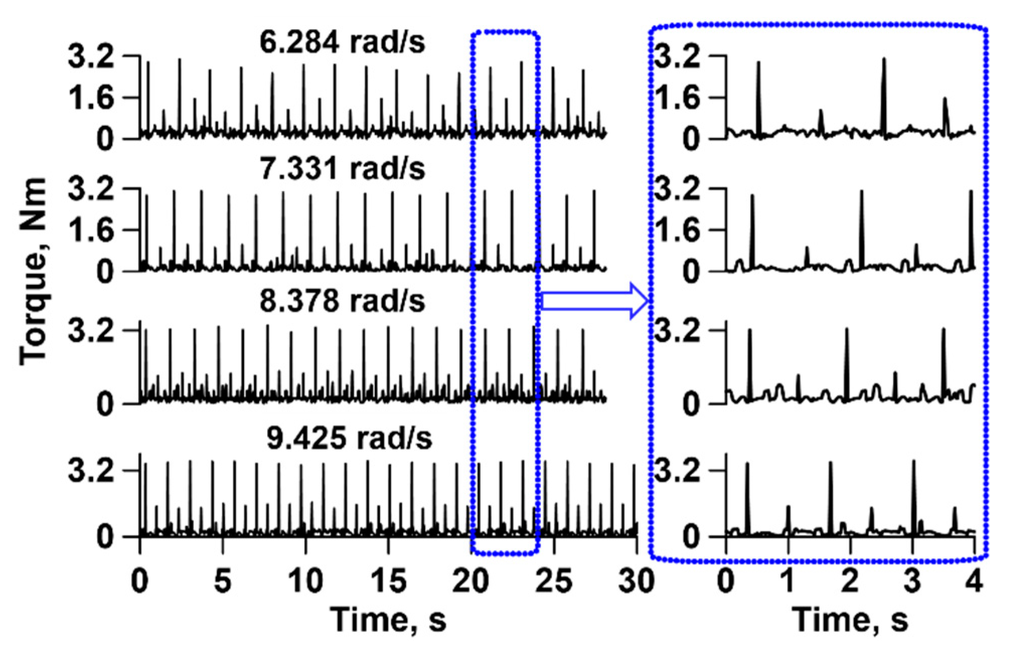
| Operating condition | 2.95 Nm @ 6.284 rad/s | |||
| Parameter | Specification |
|---|---|
| Lifespan | 10 year |
| Annual usage | 25.5 h |
| Operating speed | 6.284, 7.331, 8.378, and 9.425 rad/s |
| Cycle counting method | Load duration distribution |
| Parameter | Specification | |
|---|---|---|
| Electric motor | Rated power, kW | 1.5 @ 366.52 rad/s |
| Rated torque, Nm | 3.5 | |
| Operating speed, rad/s | 6.284, 7.331, 8.378, and 9.425 | |
| Rotational Speed, rad/s | Face Width, mm | |||
|---|---|---|---|---|
| AISI 1060 Steel | SCM 420H Carbon Steel | |||
| Crank Gear | Cam Gear | Crank Gear | Cam Gear | |
| 6.284 | 4.50 | 4.06 | 4.29 | 3.87 |
| 7.331 | 4.56 | 4.10 | 4.36 | 3.92 |
| 8.378 | 4.82 | 4.33 | 4.60 | 4.13 |
| 9.425 | 5.45 | 4.88 | 5.20 | 4.65 |
| Load Type | Case | Roll Angle, rad | Crank Gear Set Maximum Stress, MPa | |||
|---|---|---|---|---|---|---|
| SCM 420H Carbon Steel | AISI 1060 Steel | |||||
| 3 mm Face Width | 5 mm Face Width | 3 mm Face Width | 5 mm Face Width | |||
| Half load | 1 | 0.02 | 137.65 | 177.39 | 149.16 | 203.93 |
| 2 | 0.04 | 808.64 | 451.56 | 853.08 | 523.30 | |
| 3 | 0.06 | 855.48 | 519.96 | 890.97 | 636.33 | |
| Full load | 4 | 0.08 | 890.96 | 576.07 | 885.06 | 671.71 |
| 5 | 0.10 | 804.97 | 613.78 | 837.69 | 665.92 | |
| 6 | 0.12 | 631.63 | 597.10 | 700.32 | 695.02 | |
| 7 | 0.14 | 496.23 | 498.34 | 518.65 | 562.09 | |
| Half load | 8 | 0.16 | 318.29 | 321.68 | 335.30 | 410.71 |
| 9 | 0.18 | 228.34 | 262.58 | 242.62 | 278.18 | |
| 10 | 0.20 | 128.21 | 143.05 | 137.61 | 168.09 | |
| Full load | AGMA (6.284 rad/s) | 724.22 | 560.98 | 731.12 | 566.32 | |
| Load Type | Case | Roll Angle, rad | Cam Gear Set Maximum Stress, MPa | |||
|---|---|---|---|---|---|---|
| SCM 420H Carbon Steel | AISI 1060 Steel | |||||
| 3 mm Face Width | 5 mm Face Width | 3 mm Face Width | 5 mm Face Width | |||
| Half load | 1 | 0.01 | 151.05 | 147.17 | 155.23 | 151.00 |
| 2 | 0.03 | 251.24 | 260.90 | 259.58 | 271.48 | |
| 3 | 0.04 | 575.63 | 504.17 | 630.88 | 580.26 | |
| Full load | 4 | 0.06 | 769.05 | 566.61 | 786.35 | 584.02 |
| 5 | 0.07 | 702.44 | 567.04 | 745.25 | 576.09 | |
| 6 | 0.09 | 710.74 | 522.31 | 701.26 | 607.67 | |
| 7 | 0.10 | 675.44 | 507.65 | 672.49 | 524.94 | |
| Half load | 8 | 0.12 | 396.16 | 456.60 | 405.07 | 466.20 |
| 9 | 0.13 | 265.14 | 291.71 | 283.62 | 303.83 | |
| 10 | 0.15 | 173.74 | 199.77 | 184.79 | 211.27 | |
| Full load | AGMA (6.284 rad/s) | 620.63 | 480.74 | 626.54 | 485.31 | |
| Stress Bin | 9.425 rad/s | 8.378 rad/s | 7.331 rad/s | 6.284 rad/s | ||||
|---|---|---|---|---|---|---|---|---|
| Torque, Nm | Duration, h | Torque, Nm | Duration, h | Torque, Nm | Duration, h | Torque, Nm | Duration, h | |
| 1 | 0.18 | 36,133.50 | 0.21 | 30,982.50 | 0.12 | 176,205 | 0.22 | 175,567.50 |
| 2 | 0.67 | 892.50 | 0.63 | 6273 | 0.40 | 10,710 | 0.55 | 9562.50 |
| 3 | 1.38 | 255 | 1.24 | 280.50 | 0.97 | 2040 | 1.10 | 2550 |
| 4 | 1.45 | 408 | 1.36 | 255 | 1.21 | 255 | 0.00 | 0 |
| 5 | 0.00 | 0.00 | 0.00 | 0 | 0.00 | 0 | 1.64 | 1020 |
| 6 | 3.55 | 535.50 | 3.24 | 459 | 3.02 | 1912.50 | 2.96 | 1020 |
Publisher’s Note: MDPI stays neutral with regard to jurisdictional claims in published maps and institutional affiliations. |
© 2021 by the authors. Licensee MDPI, Basel, Switzerland. This article is an open access article distributed under the terms and conditions of the Creative Commons Attribution (CC BY) license (http://creativecommons.org/licenses/by/4.0/).
Share and Cite
Islam, M.N.; Iqbal, M.Z.; Chowdhury, M.; Ali, M.; Shafik, K.; Kabir, M.S.N.; Lee, D.-H.; Chung, S.-O. Stress and Fatigue Analysis of Picking Device Gears for a 2.6 kW Automatic Pepper Transplanter. Appl. Sci. 2021, 11, 2241. https://doi.org/10.3390/app11052241
Islam MN, Iqbal MZ, Chowdhury M, Ali M, Shafik K, Kabir MSN, Lee D-H, Chung S-O. Stress and Fatigue Analysis of Picking Device Gears for a 2.6 kW Automatic Pepper Transplanter. Applied Sciences. 2021; 11(5):2241. https://doi.org/10.3390/app11052241
Chicago/Turabian StyleIslam, Md Nafiul, Md Zafar Iqbal, Milon Chowdhury, Mohammod Ali, Kiraga Shafik, Md Shaha Nur Kabir, Dae-Hyun Lee, and Sun-Ok Chung. 2021. "Stress and Fatigue Analysis of Picking Device Gears for a 2.6 kW Automatic Pepper Transplanter" Applied Sciences 11, no. 5: 2241. https://doi.org/10.3390/app11052241