Article

Assessment of Structural Dynamic Response and Vehicle-Track Interaction of Precast Slab Track Systems

1
Department of Transportation System Engineering, KRRI School, University of Science and Technology, 217, Gajeong-ro, Yuseong-gu, Daejeon 34113, Korea
2
Korea Railroad Research Institute 176, Cheoldo-bangmulgwan-ro, Uiwang 16105, Gyeonggi-do, Korea
*
Author to whom correspondence should be addressed.
Appl. Sci. 2021, 11(8), 3558; https://doi.org/10.3390/app11083558
Submission received: 11 March 2021 / Revised: 1 April 2021 / Accepted: 13 April 2021 / Published: 15 April 2021
(This article belongs to the Section Civil Engineering)

Abstract

:

Featured Application

Structural Dynamic Responses of Precast Slab Track systems.

Abstract

Recently, precast slab tracks have been used widely in railway applications, especially in conventional urban railway lines. These types of tracks are rapidly constructed and limit interruptions to train operation. However, the problems of dynamic stability when the trains run on the discontinuous type of tracks must be seriously considered. This paper focuses on analyzing the train-track interaction in two types of tracks under the dynamic load by using the numerical analysis program (APATSI) to evaluate the structural response as well as the running safety to precisely understand the load transfer efficiency of precast slab track systems.

1. Introduction

In railway engineering, the ballasted track system with concrete sleeper is the major type that is generally used in conventional lines. However, the biggest drawbacks of this system are insufficient ballast depth and ballast fouling that causes the degradation of the track as well as affecting the drainage capacity of the track [1,2,3]. Moreover, the maintenance cost of the ballasted track is also mentioned as a limitation when operating this system. As a result, it is necessary to improve the track structure as an innovative solution has been offered. Nowadays, with the development of technology, concrete slab track systems are an alternative method that can solve these problems of the ballasted track with their excellent durability under the trainloads created by the high speed or the increasing of the axle load [4]. Although the initial construction cost of concrete track structure is 1.3–1.5 times higher than ballasted track, the Life Cycle Cost evaluation pointed out that it is possible in the long term this cost can be recovered after 11–12 years of operation based on the maintenance costs [5].
There are two types of concrete slab track or ballast-less system: (1) The continuous concrete slab track, which is built with cast-in-situ concrete slabs, and (2) the discrete concrete slab track, which uses precast slabs [6,7,8,9,10]. The previous study pointed out that, although the cast-in-place concrete slab track has been used widely over the world, there are many disadvantages of this type of track such as poor quality of concrete slab, limits on the track installation, and the effects of air pollution that can affect the workers’ health when constructing underground as well as in the tunnel section [11]. In contrast, the precast slab track, which is made in the factory, can prevent these issues. The main requirements of precast slab track are rapid installation, huge bearing capacity (huge train loads and train speed), high quality of concrete slab, safety, and that it is friendly to the environment. This type of track is being developed and applied in many countries. There are a lot of different types of prefabricated slab track systems. Japan has the Shinkansen system [12], where the 5 m length of precast slab panels are mounted on the continuously concrete base. After adjusting the level of the slab, an asphalt cement layer is poured to connect the panels and basements. The CRTS system was developed in China [13,14,15,16,17], this is the most popular method used to install in Chinese high-speed railway line. This ballastless system is composed of a superstructure (rail, fastening system, and slab panel), self-compacting concrete layer, isolator layer, and plate base [18]. Additionally, the Bögl system was installed in Germany [19,20,21]. The precast slab tracks usually consist of three layers the slab panels on the top, the grouting layer, and then the subgrade, as can be seen in Figure 1. When constructing the precast slab track, the rails were mounted on the panels by fastening systems; after that, the whole structure (rail-fastener-panel) was assembled on the concrete base. Finally, the grout was poured between the slab panels and the base after adjusting the upper structures.
In this paper, we changed the grout layer of the precast slab track by the elastic support systems and developed new precast slab track structures. After the design and testing of the structural behaviors in the laboratory, we determined the dynamic behavior of the structure through the numerical analysis program (All-Purpose Analysis of Train Structure Interaction—APATSI), which has been developed by the Korea Railroad Research Institute. We focused on the performance of the structures under the dynamic load to verify the structure deflection. These types of tracks have no dowel bar or steel plate to connect each panel, and the trainload is transmitted and contributed from the rails to the slab panel. Therefore, it is necessary to evaluate the Load Transfer Efficiency of these types of tracks through the structure deflection. The goal of this study is to evaluate the train-track interaction and the structural behaviors under the dynamic load (urban conventional trainset) to understand more accurately the safety of these track systems.

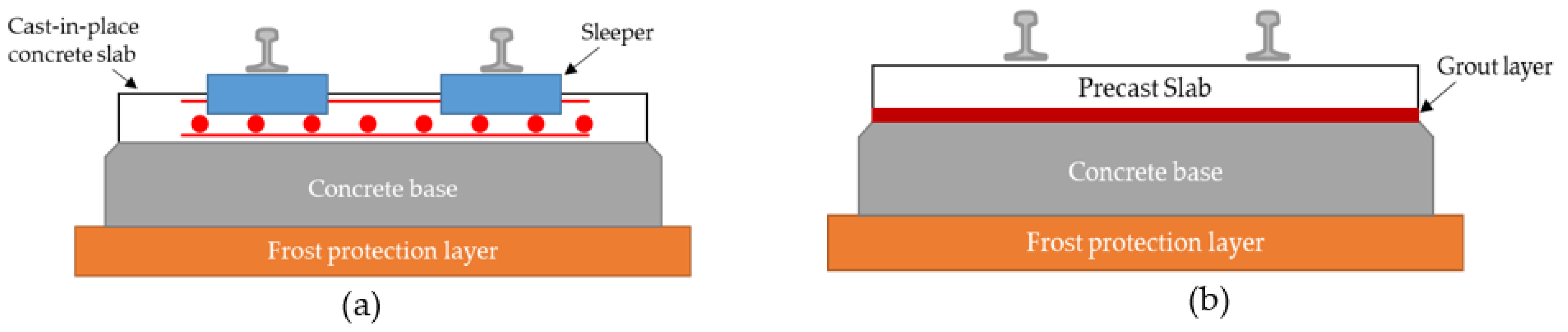
2. Precast Slab Panels

Recently, two new types of precast slab track have been studied and improved to apply to conventional railway lines as shown in Figure 2. In our study, the grouting layer was changed by the elastic support devices, which can rapidly construct the concrete track system. The basic specification of these precast slab panels is listed in Table 1. The most remarkable improvement of these precast slab track systems is that the trainloads will be transmitted between the panels (the distance of panels is 75 mm) by the rails instead of the steel connection joints. This method can reduce the construction cost by 10%, according to the studies of concrete pavements [22].

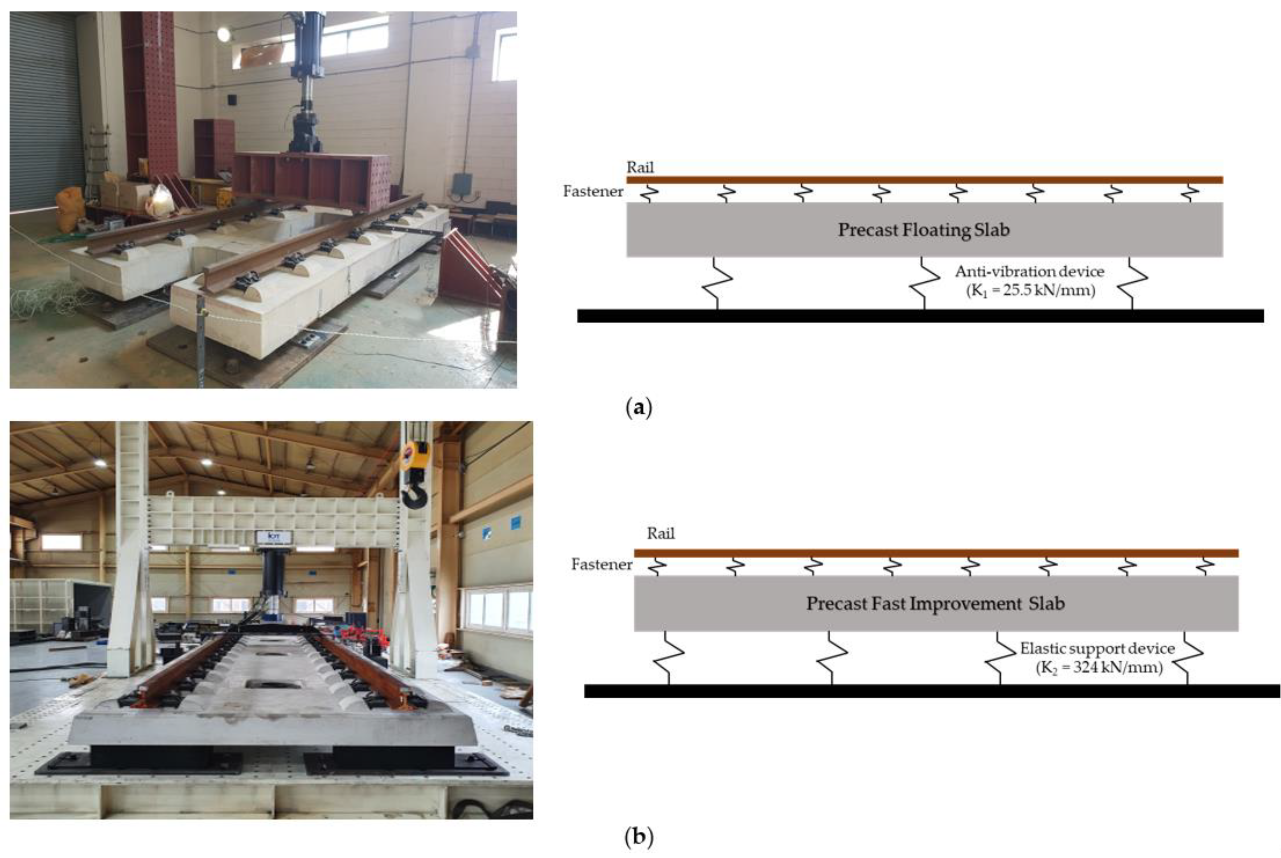
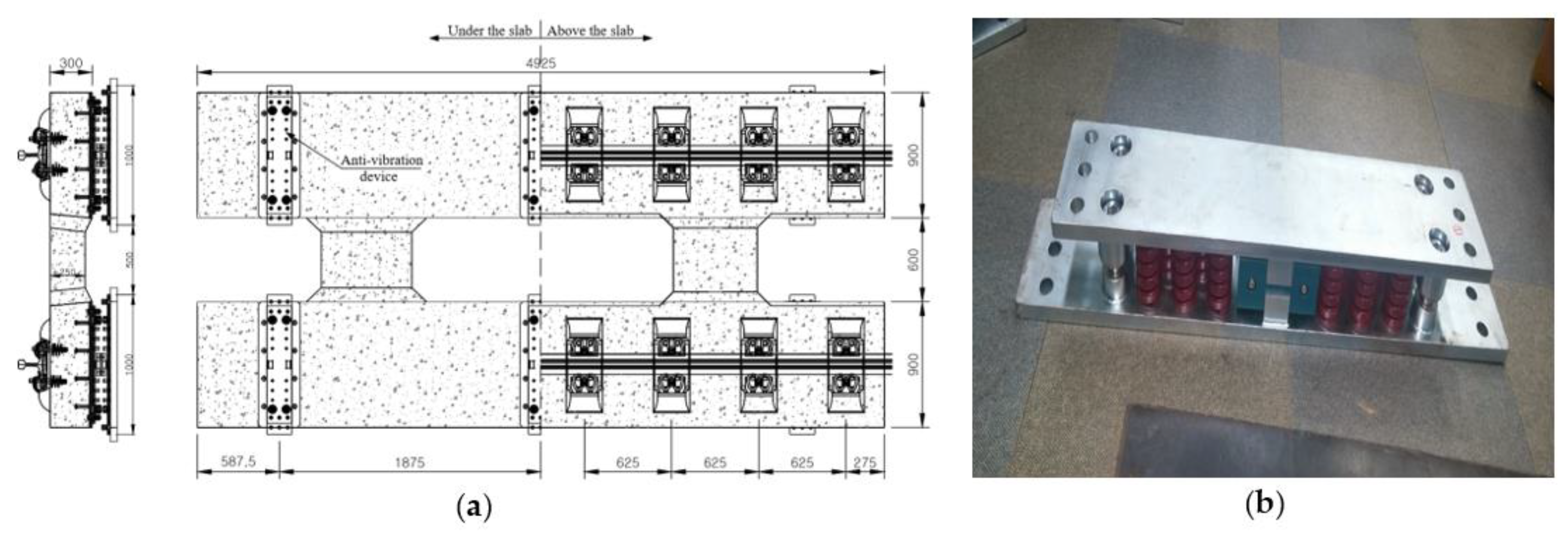
2.1. Precast Slab Track Type I

The Type I slab panel is named “Precast floating slab track,” and it is designed to be used for the urban railway. The main function of this type is to reduce the ground-borne noise and vibration issues generated from the train-track interaction when operating the train, especially in underground and bridge sections of metro lines. This type has the dimensions were 4.925 m (length) × 2.4 m (width) × 0.3 m (thickness). Figure 3a shows the details of this precast floating slab track. The design strength of the slab concrete is 45 MPa. This type of slab was composed of two concrete blocks connected with the crossbeams. Rails were mounted on the slab panel by the fastening device system (Vossloh System 300-1). In the prototype, six coil spring elastic devices (with a vertical stiffness of 22.5 KN/mm) were attached at the bottom of each panel. These devices use the frictional resistance of a wedge-shaped block made of engineering plastic applied to an inclined surface to attenuate vertical vibrations, providing resilience through coil springs arranged horizontally and vertically to insulate vibration. By applying the Mass–Spring–Systems (composed of the rail, fastener, and concrete slab panel) combined with the anti-vibration devices, the floating slab track has become one of the most typical methods to reduce the noise and vibration problems in railway. When constructing the track, the concrete base was adjusted with a fixed height of the track. After that, the panels were transported to the site and assembled sequentially by using the hydraulic jack machine. This type of track can be constructed 10 m per day without interrupting the train operation.

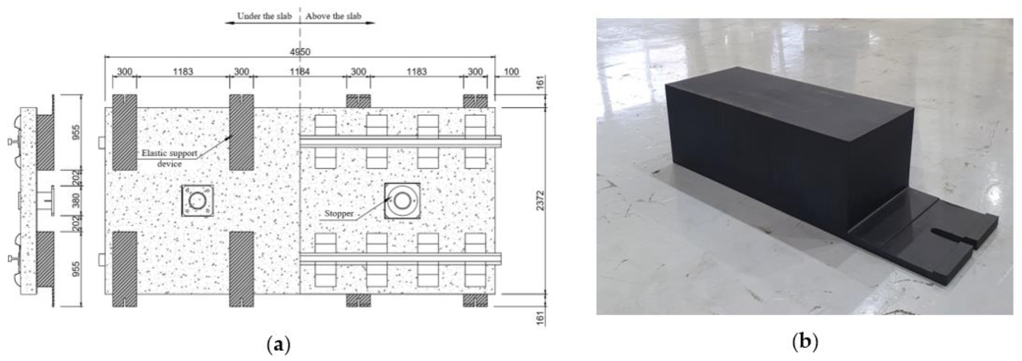
2.2. Precast Slab Track Type II

The main goals of this type of track are to rapidly replace the conventional ballasted track with the concrete track in difficult conditions such as lack of working space and lack of working hours, especially in tunnel sections of urban railway lines. The Precast-Fast Improvement slab Track (P-FIT) can be constructed 20 m per day at nighttime so that the train operation still can work on the next day. This type of slab track has dimensions of 4.950 m (length) × 2.38 m (width) × 0.23 m (thickness). Figure 4a shows the details of this precast slab track. The designed strength of the slab concrete is 45 MPa. Rails were mounted on the slab panel by the fastening device system (Vossloh System 300-1). At the bottom of the panel, 8 elastic devices—rubber type in Figure 4b—were attached to support the lower part of the structure. This elastic device can be manufactured by laminated rubber that meets the standard of fire situations. The Rapid Construction Precast slab track has 2 stoppers in the middle of the panel to resist the horizontal force (centrifugal force) and the longitudinal force (braking force) when the trains are operated.

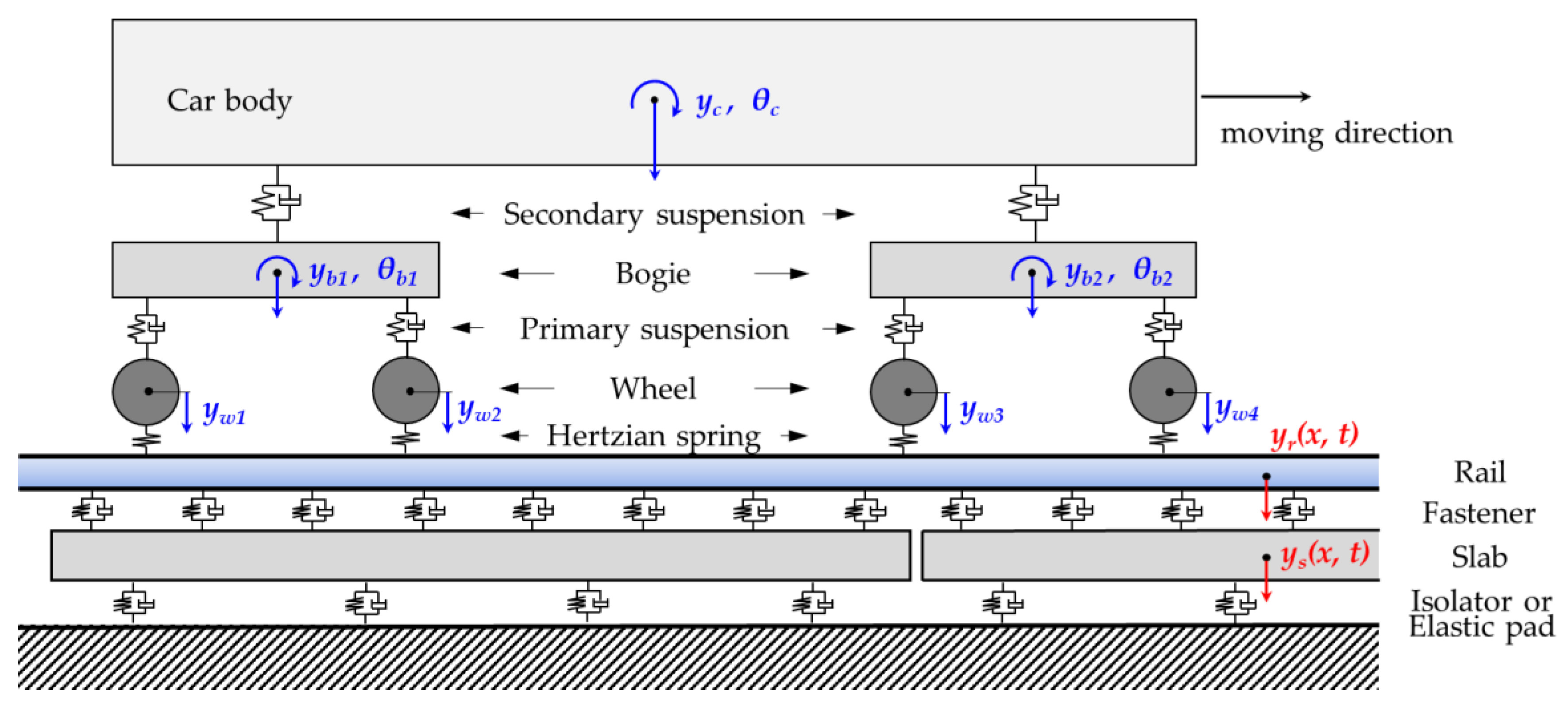
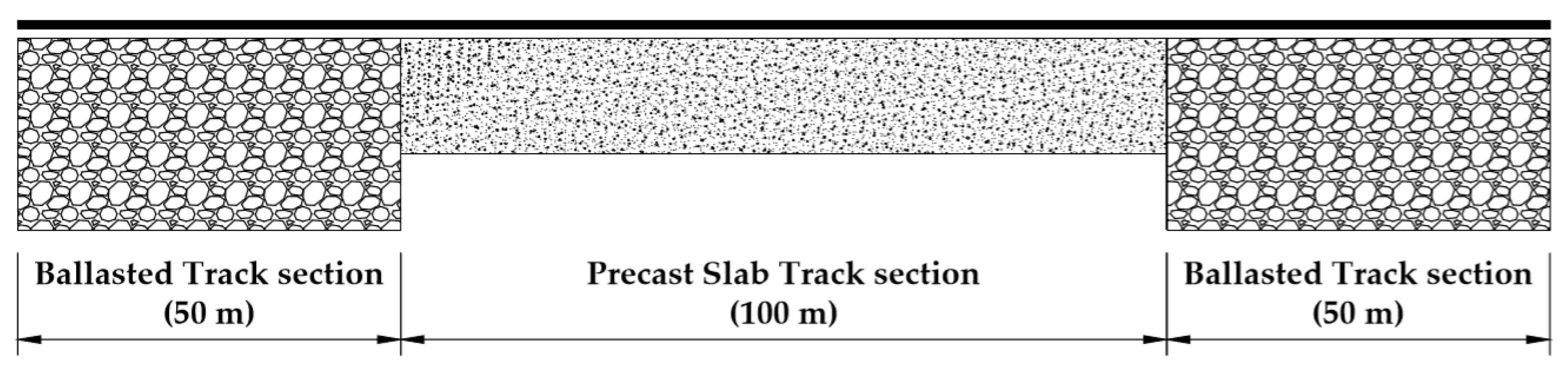
3. Numerical Analysis

The train-track interaction analysis was performed according to the method proposed by Yang et al. [23,24,25] to investigate and compare the performance of the precast floating and rapid track. The vehicle consists of a rigid bodied car body, 2 bogies, and 4 wheels and spring-dampers connecting between them for primary and secondary suspensions, as shown in Figure 5. The track consists of rail and slab that are modeled based on the Timoshenko beam theory for rail and the Euler–Bernoulli theory for slab panel. The rail is considered as the first layer and modeled as the continuous beam element, while the slab track is the second layer and simulated as the discrete supported beam element. The spring-dampers of the fastener are connected the rail and slab, and the slab is supported by vibration isolators. These structures are simulated as the linear spring and damping elements.
The motion equation for the vehicle-track interaction system is presented by following formula:
M Y ¨ +   C Y ˙   +   KY   =   F
Y , the displacement vector of the system can be expressed.
Y   = { Y v Y t } T
Y v = { y c ,   θ v ,   y b 1 ,   θ b 1 ,   y b 2 ,   θ b 2 ,   y w 1 ,   y w 2 ,   y w 3 ,   y w 4 } T
Y t = { y ri ,   θ ri ,   y si ,   θ si } T i = 1   ~   n
where y and θ are vertical and rotational displacement, subscripts v and t mean vehicle and track, and c, b, and w indicate car body, bogie, and wheel, respectively. y ri , θ ri , y si , and θ si are i-th nodal displacements of the FE models, which have n nodes, for rail and slab, respectively. The mass, damping, and stiffness matrices of the system can be induced as
M = [ M v 0 M r 0 M s ] ,   C = [ C v 0 0 0 C r C rs 0 C rs C s ] ,   K = [ K v 0 0 0 K r K rs 0 K rs K s ]
in which system matrices of rail, M r ,   K r , and slab, M s ,   K s , are derived by FE modeling. Subscript rs represents coupled parts between rail and slab by fastener. The force vector F can be written as
F   = { F v F t 0 2 n × 1 } T
F v = { 0 6 × 1   F H 1   F H 2   F H 3   F H 4 } T
F t = i 4 [ Φ ( x ci )   f si +   Φ ( x ci )   F Hi   ]
where Φ ( x ci ) is the location vector of wheel-rail contact, which has values of { φ 1 ( x ci )   φ 2 ( x ci )   φ 3 ( x ci )   φ 4 ( x ci ) } T at the corresponding nodes with the contact location and the others are zero; x ci is local coordinate of i -th wheel-rail contact point in a FE element; and f si is static load of vehicle acting on i -th wheel-rail contact point. F Hi   ( i = 1   ~   4 ) are the contact forces by Hertzian spring between the wheels and rail, and can be obtained as follows [23]. The boundary conditions are simulated by two points. The starting point is from 0 m to the 200 m point of the rail as a first layer.
F Hi = { K H 1 +   α ( x ci ) K H   { y wi   y r ( x ci ) } if   { y wi   y r ( x ci ) } > 0 0 else
where K H is the linearized Hertzian spring coefficient satisfying the following characteristic equation:
α ( x ci ) K H 3 +   K H 2   c H 2   { y wi   y r ( x ci ) } = 0
And α ( ξ c ) is given by:
α ( x ci ) = { x ci ( L x ci ) [ 4   x ci 2 ( L x ci ) 2 + ( x ci L 3   x ci 2 L 2 + L 4 ) ψ s + ψ s 2 ] } 12 EI ( 1 + ψ s )  
where:
ψ s = 12 EI GA r L 2
and EI , G , A r , and L are the flexural stiffness, shear modulus, cross-sectional area of the rail, and element length, respectively. In this paper, the precast slab track systems were composed by the slab panel with a short length (approximately 5-m length per panel) to ensure rapid installation. Moreover, there was a distance (75 mm) between panels without using the dowel bar to join the slabs. Thus, the discontinuous points will occur while operating the train. Besides, the transition zone (ballasted track–slab track) was also considered and modeled in this study. By using the APATSI program, the structural responses, driving safety, and load transfer efficiency of two types of the track were evaluated.
Using the above mathematical model, the train-track interaction analysis was performed while a train moved at 110 km/h. The train we used is an urban trainset, which is being operated in South Korea, and consists of 6 cars with 3 motor cars and 3 passenger cars, as shown in Figure 6. Since the train is symmetric concerning the longitudinal direction, the half models are used, which is summarized in Table 2.
A 200 m length of track was simulated, which is 100 m of ballasted track and 100 m of precast slab track, as shown in Figure 7. The details of structures and track systems were presented in Table 3. Two types of precast slab tracks use the same kinds of the superstructure. The differences are the elastic devices attached at the bottom of each type of slab track and the distance between the devices as shown in Figure 3 and Figure 4.

4. Results and Discussion

With the above specifications of train and track structure, the analysis was calculated by using the finite element program All-Purpose Analysis of Train Structure Interaction (APATSI), which was developed by the Korea Railroad Research Institute. The results of train-track interaction and the structural behaviors are shown as follows.

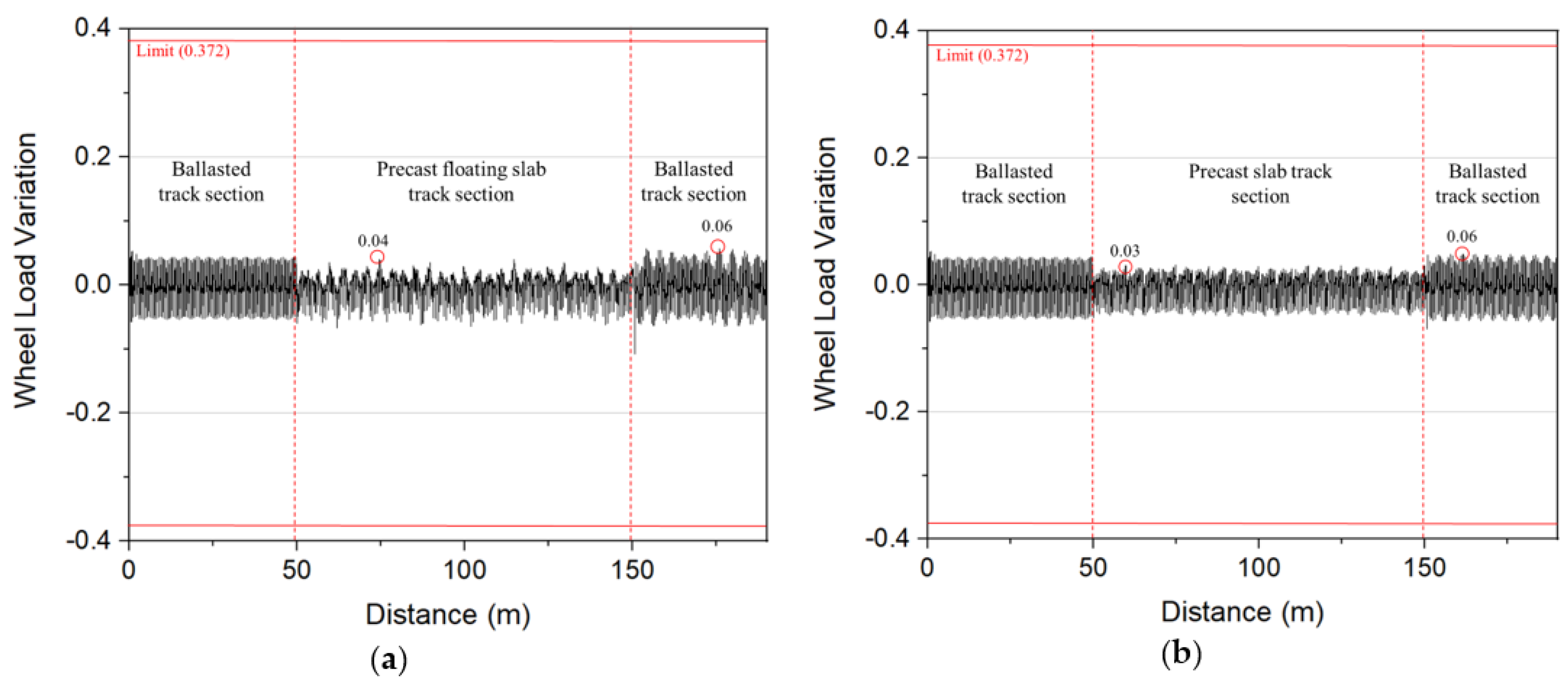
4.1. Wheel Load Variation

The driving safety can be evaluated by predicting the possibility of derailment when operating the train. The derailment ratio and the reduction rate of the wheel are calculated in the following formulas.
K Q / P = Q P = 8 3 α h 1 α v
η = Δ P P 0 = α v
where:
  • KQ/P: Derailment ratio.
  • Q: Lateral force.
  • P: Dynamic wheel weight due to track distortion.
  • αh, αv: Horizontal and vertical accelerations of the vehicle body, respectively.
  • η: Wheel reduction rate.
  • P0, ΔP: Static wheel load and variation in the wheel weight.
In this paper, the criteria for the wheel load variation ratio were used by 0.372 according to Jang and Yang [26], and the rules on safety standard for railroad vehicles by the Korea Ministry of Land, Infrastructure, and Transport and the design standard for railway structures by Japanese Railway Technical Research Institute were used.
In Figure 8, the wheel force variation results are described. The maximum wheel force variation rate in ballasted track was 0.06. Meanwhile, this value of precast slab track Type I and II decreased 33.33% and 50% compared to ballasted track. These results showed that the train runs more stable in the precast slab track sections. The limited rate change of wheel load is 0.372 so that both types of precast slab track acquired the requirement. However, as can be seen in Figure 8, the train operated slightly smoother in the Type II than Type I section. There is a small change in wheel force when the train runs from the precast floating track to the ballasted track at the connection zone. Therefore, it is necessary to increase the rigidity at the transition part when designing the floating slab track.

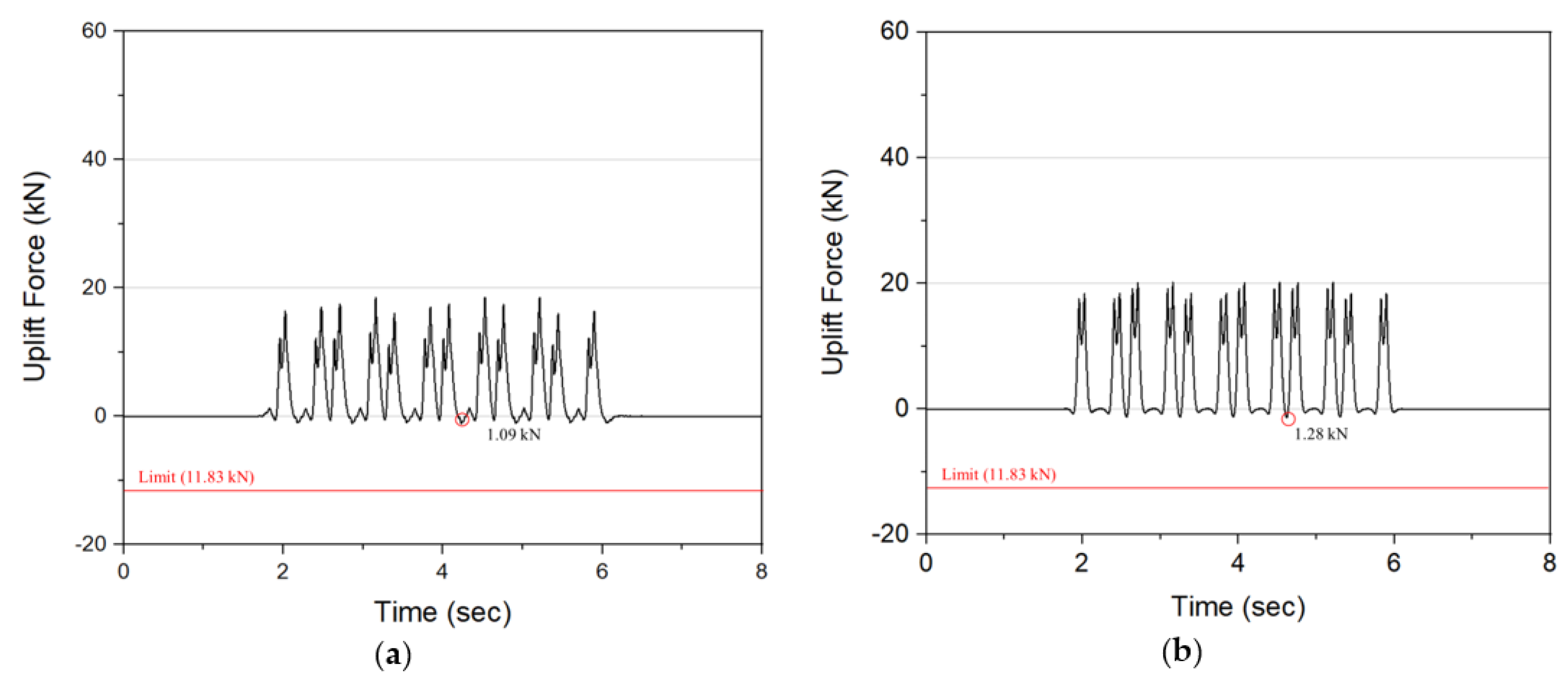
4.2. Rail Uplift Force and Rail Stress

When designing a precast slab track, the performance of components such as fasteners, slabs, and elastic devices can be secured by applying each performance standard or structural design standard. However, even though each component requires performance, if they behave systematically in a combined state, the performance of the system’s usability should be confirmed considering long-term maintenance [26]. In the track system, if the rail stresses and rail uplift forces are huge, the life of the rail and fastener become shortened and the maintenance cost will increase by changing the rail pad. Therefore, it is important to evaluate these problems.
Figure 9 shows the results of rail uplift force when the train runs on the middle panel of both types of track. The rail uplift force must not be greater than the initial clamping force of the rail fastener so that the rail pad cannot move or twist. In these types of precast slab tracks, the Vossloh System 300-1 type of fastener was used to connect rails with the concrete panel. The initial clamping force of this device is 16.9 kN and the allowable force is 70% of this value, equal to 11.83 kN [26]. As can be seen in Figure 9, the rail uplift force of both types of precast slab track met the requirement. The maximum uplift force of Type I was 1.09 kN, while the force of Type II was slightly larger (1.28 kN).
In this paper, the KR-60 rail was mounted on both types of precast slab tracks. The allowable stress of the KR-60 rail is normally 130 MPa [5]. The reference value to analyze the rail stresses is 70% [27] of 130 MPa and equal to 90 MPa. Figure 10 describes the rail bottom stress of precast slab track systems when operating the train.
As can be seen in Figure 10, the rail bottom stress in the precast slab track systems section was larger than ballasted section. The maximum rail bottom stresses occurred at the transition point between ballasted section and precast slab track section. This happened due to the change of supported stiffness when the train runs from the ballast track to the concrete track. The precast slab track Type II has a distance of the elastic devices closer and stiffer than Type I, so the maximum of rail bottom stress of Type II was smaller than Type I.

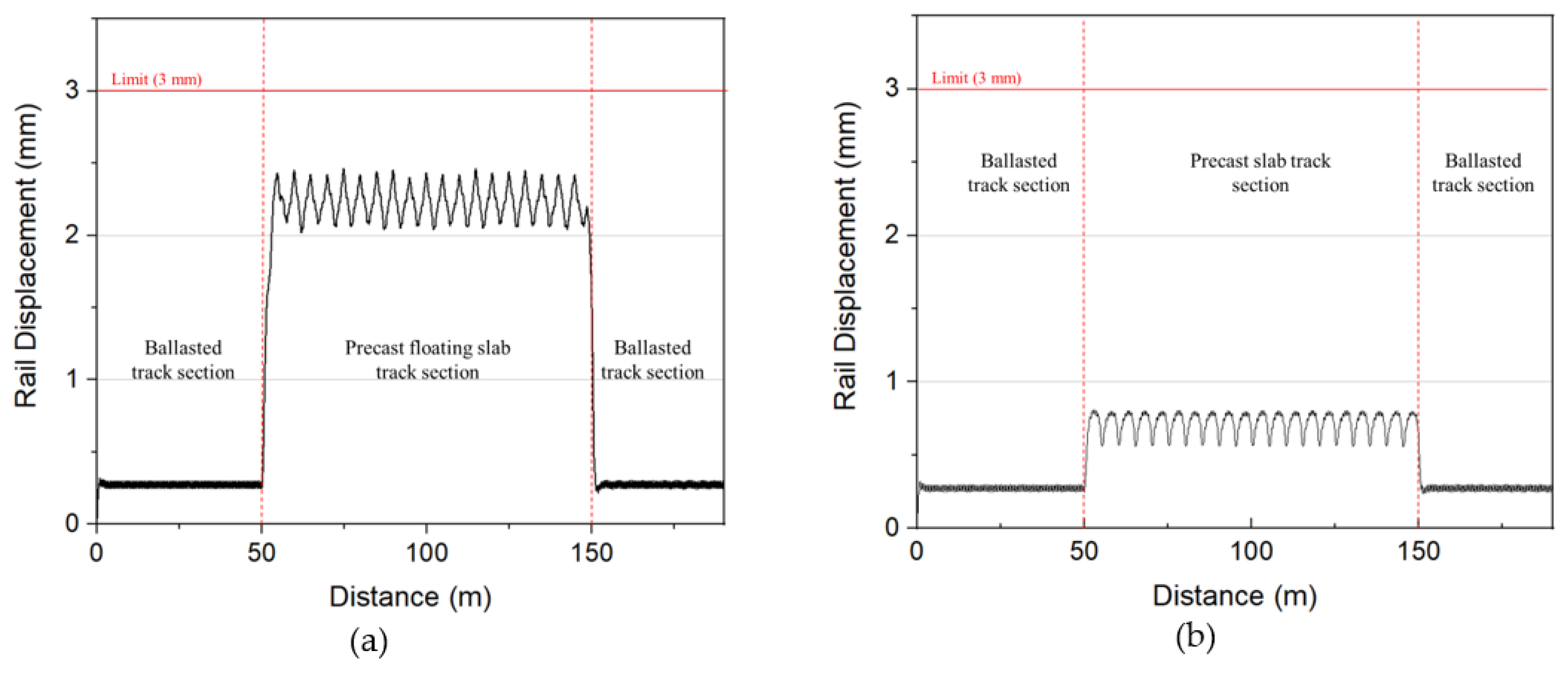
4.3. Rail Relative Displacement

Figure 11 shows the rail relative deflection of the Precast Floating slab track and Precast-Fast Improvement slab Track under the urban railway trains at a speed of 110 km/h. Based on the Japanese standard for railway structure, the relative displacement of rails should not exceed 3 mm to ensure the running safety of the vehicles [28]. In general, the rail displacement of both types of precast slab track met the allowable criteria (under 3 mm). It can be seen in Figure 11a that the rail displacement increased by 2.1 mm when the vehicle runs over the connection from the ballasted track to precast Type I. However, in Figure 11b, at the same part, the rail deflection only raised 0.5 mm. When applying the moving load, the maximum rail displacement of Type I was 3 times higher than Type II. Therefore, the stiffness of the elastic device greatly affected the rail deflection because both types of precast slab track used the same type of fastener and rail pad.

4.4. Load Transfer Efficiency

Both types of precast slab tracks used rail to transmit the wheel load between slab panels with a distance of 75 mm instead of dowel bars or steel joints. This advantage can reduce the initial construction cost of concrete slab track [22]. To evaluate the safety when the train is operating on the track, the relative displacement between panels is particularly important. If a step difference occurs in the rail, the dynamic performance of the train will be affected, such as increasing of car body acceleration as well as high stresses of rail [1]. Therefore, it is necessary to measure the Load Transfer Efficiency (LTE) of the track under the moving load. This characteristic can be calculated by the following formula.
LTE = δ 2 ( δ 1 + δ 2 2 ) = 2 δ 2 δ 1 + δ 2
where:
  • δ1: is the rail displacement at loaded panel (mm).
  • δ2: is the rail displacement at adjacent panel (mm).
The results of LTE are shown in Table 4. According to the results, the step difference, inclination and LTE were calculated from the 1st panel to the 20th panel in both types of the track (equal to the 100-m length of slab track). The rail relative deflection of Track Type I is 4 times larger than Type II in both loaded panels and adjacent panels. The Precast Floating slab track had the rail relative displacements ranging from 2.62 to 2.71 mm at loaded panels and from 2.57 to 2.66 mm at the unloaded ones. These values of the Precast-Fast Improvement slab Track were 0.689 to 0.694 mm at loaded panels and 0.648 to 0.659 mm at the adjacent panels. The reason is the supporting devices of Type I are more elastic than Type II. Meanwhile, the average Load Transfer Efficiency in both types of precast slab track was 98.80% and 97.28%. These results show that they can transfer almost completely the trainload from panel to panel without using any connection joints. Based on the Japanese standard usability for high-speed railway structure, the limit angular rotation values in the vertical direction by riding comfort is 2.5‰, and by running safety is 2.0‰. When the distance of the panel is 75 mm, the maximum rail inclination of Type I is 1.07‰ and Type II is 0.53‰ between the 19th and 20th panels. It means these types of precast slab tracks can secure safety as well as riding comfort when the train passes by.

5. Conclusions

In this paper, the Precast Floating Slab track (type I) and Precast Fast Improvement slab track (type II) were developed and designed as the alternative method to ballasted track. These types of tracks are supported discretely and the gap between each panel (75 mm). Moreover, there is no connection joint or dowel bar to transmit the load from the slabs so the rail will take on the role of transferring the wheel load when operating the trains. Therefore, it is necessary to consider the dynamic performance of the structures as well as the running safety of the precast slab tracks through the train-track interaction. This study focused on analyzing 200 m length combined of these types of precast slab track and ballasted track with conventional metro trainset (designed speed 110 km/h) by using the numerical program All-Purpose Analysis of Train-Substructure Interaction (APATSI). After calculating and comparing the results, these conclusions are summarized as below:
  • The wheel force variation of both types of tracks was almost similar and met the requirement (smaller than the limitation is 0.372). However, when the train runs from the ballasted track to the Precast Floating slab track (Type I), there was a sudden change of wheel load. The reason is the huge difference in elasticity between the ballast layer and the anti-vibration device attached at the bottom of this type of track. Thus, it will be needed to increase the rigidity at the transition zone when designing this section.
  • To ensure comfort when the train running, the rail uplift force of precast slab track systems should not exceed 11.83 kN (which is 70% of the clamping force of fastening systems Vossloh 300-1 system-16.9 kN). The results showed that the maximum rail uplift force of Type II was slightly larger than Type I. In general, these results of both types of tracks satisfied the acceptance criteria and guarantee the riding comfort of the train.
  • Both types of tracks used the same kind of rail (KR 60 type). When applied to the conventional trainset, the rail bottom stress of Type I is 1.24 times larger than Type II, especially at the transition zone between the ballasted track and slab track. The main cause was that Type II had the stiffer elastic devices, and the distance of these devices was closer than Type I. However, the result of stress in both types of the track was smaller than the allowable stress (90 MPa).
  • According to the Japanese standard for displacement limit of structure in railway application, the rail displacement must be smaller than 3 mm. From the results, the maximum rail relative displacement of Type I was 3 times higher than Type II. When the train was operating at the connection zone between ballasted track and slab track, the rail deflection of Type I rose 4.2 times higher than Type II. This means the elasticity of the supporting device has a huge effect on rail displacement.
  • Finally, instead of using steel bars to connect the slab panels, the trainload was transmitted by the KR-60 rail. The step and inclination as well as the load transfer efficiency (LTE) between 20 slab panels were evaluated. As can be seen from the results, the step was smaller than the standard (2 mm), and the maximum inclination of the rail at the 75 mm distance of slabs was 1.07‰ for Type I and 0.53‰ for Type II, which met the requirement of the standard for riding comfort (2.5‰) and running safety (2.0‰) in Japan. The average LTE of Type I and Type II was 98.80% and 97.28%, respectively. Thus, these types of tracks can perfectly transmit the wheel load when the train passes by.

Author Contributions

Conceptualization, L.V.; Data curation, L.V.; Formal analysis, L.V.; Funding acquisition, Y.-S.K.; Methodology, D.-D.J.; Project administration, Y.-S.K.; Software, D.-D.J.; Supervision, Y.-S.K.; Writing—original draft, L.V.; Writing—review & editing, D.-D.J. All authors have read and agreed to the published version of the manuscript.

Funding

This research was supported by a grant from R&D Program (PK2103B1) of the Korea Railroad Research Institute, Korea.

Institutional Review Board Statement

Not applicable.

Informed Consent Statement

Not applicable.

Data Availability Statement

The data presented in this study are available on request from the corresponding author.

Acknowledgments

This research was supported by a grant from R&D Program (PK2103B1) of the Korea Railroad Research Institute, Korea.

Conflicts of Interest

The authors declare no conflict of interest.

References

  1. Vu, L.; Kang, Y.S. Load transfer efficiency based on structural deflection assessment of the precast floating track. Appl. Sci. 2021, 11, 120. [Google Scholar] [CrossRef]
  2. Birhane, F.N.; Choi, Y.T.; Lee, S.J. Development of GPR device and analysis method to detect thickness of ballast layer. J. Korean Soc. Railw. 2020, 23, 269–278. [Google Scholar] [CrossRef]
  3. Koh, T.H.; Shin, M.C. Field tests on Eco-friendly railway precast concrete slab. Appl. Sci. 2020, 10, 4140. [Google Scholar] [CrossRef]
  4. Cho, Y.K.; Kim, S.M. Evaluation of grouting layer vibration of railway precast concrete slab track system. Constr. Build. Mater. 2018, 193, 244–254. [Google Scholar] [CrossRef]
  5. Kang, Y.S.; Lee, C.Y.; Jang, D.D.; Kwon, S.G.; Han, W.J.; Vu, L. Study on structural performance of precast track of discrete panel supporting type for rapid ballast improvement. J. Korean Soc. Hazard Mitig. 2020, 20, 233–244. [Google Scholar] [CrossRef]
  6. Bastin, R. Development of German non-ballasted track forms. Proc. Inst. Civ. Eng. 2006, 159, 25–39. [Google Scholar] [CrossRef]
  7. Mass, G.; Rickes, T.M.; Winter, T. Productivity in rail construction lessons learned from the development of the RHEDA 2000 track construction system. In Proceedings of the Conference: 23rd International Symposium on Automation and Robotics in Construction, Tokyo, Japan, 3–5 October 2006; pp. 246–251. [Google Scholar]
  8. Tsoukantas, S.; Giannakos, K.; Topintzis, T.; Zois, H. System Rheda 2000 from the point of view of a structural engineer–The most modern evolution of superstructure technology in railway projects. In Proceedings of the Conference of Greek Department of Concrete, Alexandroupolis, Greece, 25–27 October 2006. [Google Scholar]
  9. Freudenstein. S. RHEDA 2000®: Ballastless track systems for high-speed rail applications. Int. J. Pavament Eng. 2010, 11, 293–300. [Google Scholar] [CrossRef]
  10. Cho, Y.K.; Kim, S.M.; Chung, W.; Kim, J.C.; Oh, H.J. Effect of steel ratio on behavior of continuously reinforcement concrete railway track under environmental loads. J. Korean Soc. Civ. Eng. 2014, 18, 1688–1695. [Google Scholar]
  11. Jang, S.Y.; Kang, Y.S.; Lee, H.S.; Kim, Y.B.; Lee, J.S. Trial installation and performance evaluation of prefabricated concrete slab track on revenue line. Korean Soc. Railw J. Korean Soc. Railw. 2008 Fall Conf. 2008, 840–845. Available online: https://www.dbpia.co.kr/Journal/articleDetail?nodeId=NODE01084168 (accessed on 1 April 2021).
  12. Ando, K.; Sunaga, M.; Aoki, H.; Haga, O. Development of slab tracks for Hokuriku Shinkansen line. Q. Rep. Railw. Tech. Res. Inst. 2001, 42, 35–41. [Google Scholar] [CrossRef]
  13. Lei, X.; Zhang, B. Analysis of dynamic behavior for slab track of high-speed railway based on vehicle and track elements. J. Transp. Eng. 2011, 137, 227–240. [Google Scholar] [CrossRef]
  14. Sun, L.; Duan, Y.F.; Yang, X. Static response analysis of CRTS III ballastless track structure. J. Railw. Eng. Soc. 2013, 30, 32–39. [Google Scholar]
  15. Dai, F.; Xu, G.; Yang, J.; Liu, X. Dynamic performance of unbonded prestressed steel bar in CRTS I ballastless slab track under train load. In Proceedings of the 4th International Conference on Transportation Engineering, Chengdu, China, 19–20 October 2013; pp. 1765–1770. [Google Scholar]
  16. Ren, J.; Zhao, H.; Li, X.; Deng, S.; Xu, K. Dynamic performances of CRTS III prefabricated slab track with anti-vibration structure in subgrade-tunnel transition section. J. Southwest Jiaotong Univ. 2016, 51, 1047–1054. [Google Scholar]
  17. Ren, J.J.; Zhao, H.W.; Li, X.; Xu, K. Analysis of harmonic response of CRTS III prefabricated slab track with anti-vibration structure. J. Railw. Eng. Soc. 2016, 33, 44–50. [Google Scholar]
  18. Leykauf, G. Prefabricated slabs and frames for non-ballasted track. J. Railw. Transp. 1999, 123, 221–228. [Google Scholar]
  19. 19. Yu. Z.; Xie. Y.; Tian. X. Research on mechanical performance of CRTS III plate-type ballastless track structure under temperature load based on probability statistics. Adv. Civ. Eng. 2019. [CrossRef]
  20. Antlauf, W. Bögl system slab track: Installation on the new Nuremberg–Ingolstadt line. Eisenbahningernieur 2004, 55, 64–67. [Google Scholar]
  21. Antlauf, W. Slab track system FF bögl on the new Nuremberg-Ingolstadt line. ZEV Rail Glassers Ann. 2004, 128, 360–364. [Google Scholar]
  22. Chung, W.S.; Kwon, K.S.; Yang, S.Y. Deflection-based load transfer efficiency of floating slab track. KSCE J. Civ. Eng. 2014, 18, 616–624. [Google Scholar] [CrossRef]
  23. Yang, S.C. Enhancement of the finite-element method for the analysis of vertical train-track interactions. Proc. Inst. Mech. Eng. Part F J. Rail Rapid Transit 2009, 223, 609–620. [Google Scholar] [CrossRef]
  24. Yang, S.C.; Kim, E. Effect on vehicle and track interaction of installation faults in the concrete bearing surface of a direct-fixation track. J. Sound Vib. 2012, 331, 192–212. [Google Scholar] [CrossRef]
  25. Yang, S.C.; Hwang, S.H. Train-track-bridge interaction by coupling direct stiffness method and mode superposition method. ASCE J. Bridge Eng. 2016, 21. [Google Scholar] [CrossRef]
  26. Jang, S.Y.; Yang, S.C. Assessment of train running safety, ride comfort, and track serviceability at transition between floating slab track and conventional concrete track. J. Korean Soc. Railw. 2012, 15, 48–61. [Google Scholar] [CrossRef] [Green Version]
  27. Namura, A.; Matsuo, K.; Miura, S. Introduction of buffers into a transitional track stiffness region. RTRI Rep. 1997, 11, 39–42. (In Japanese) [Google Scholar]
  28. Railway Technology Research Institute (RTRI). Design Standards for Railway Structures and Commentary–Limit for Displacement; Maruzen: Tokyo, Japan, 2012. [Google Scholar]
Figure 1. Concrete slab track systems: (a) Cast-in-place slab track, (b) Precast slab track.
Applsci 11 03558 g001
Figure 2. Precast slab track systems: (a) Type I: Precast Floating Slab Track, (b) Type II: Precast-Fast Improvement slab Track.
Applsci 11 03558 g002
Figure 3. Precast Floating Slab Track (Type I): (a) Detailed structures, (b) Anti-vibration Device.
Applsci 11 03558 g003
Figure 4. Precast-Fast Improvement slab Track (Type II): (a) Detailed structures, (b) Rubber Elastic Support Device.
Applsci 11 03558 g004
Figure 5. Train-track interaction analysis model.
Applsci 11 03558 g005
Figure 6. The urban railway trainset of six cars.
Applsci 11 03558 g006
Figure 7. Track analysis sections.
Applsci 11 03558 g007
Figure 8. Wheel load variation results: (a) Precast Floating Slab Track (Type I), (b) Precast-Fast Improvement slab Track (Type II).
Applsci 11 03558 g008
Figure 9. Rail Uplift Force results: (a) Type I, (b) Type II.
Applsci 11 03558 g009
Figure 10. Rail bottom results: (a) Type I, (b) Type II.
Applsci 11 03558 g010
Figure 11. Rail Relative Displacement results: (a) Type I, (b) Type II.
Applsci 11 03558 g011
Table 1. Specification of specimen.
SpecificationsType IType II
Dimensions (m)4.925 (L) × 2.4 (W) × 0.3 (H)4.950 (L) × 2.38 (W) × 0.23 (H)
Concrete Strength (MPa)4545
Panel Weight (ton)7.67.6
Support Stiffness of Elastic Device (kN/mm)22.5324
Table 2. Specification of trainset (half model).
ItemUnitMotor Car
(M)
Passenger Car
(P)
Car Body
specifications
Car Body Weightton2119
Car Body Mass Moment of Inertiaton-m2791856.5
Weight of Bogieton0.6000.585
Bogie Mass Moment of Inertiaton-m20.7500.400
Weight of Wheelton0.8600.795
Primary
Suspension
Spring CoefficientMN/m10430.511
Damping CoefficientMN·s/m--
Secondary
Suspension
Spring CoefficientMN/m0.1910.176
Damping CoefficientMN·s/m--
LengthBalance Intervalm13.813.8
Distance between Wheelsm2.12.1
Radius of Wheelm0.430.43
Table 3. Specification of track systems (half model).
ParameterUnitType IType II
RailModulus of ElasticitykPa2.1 × 108
Poisson’s Ratio 0.3
Masston/m6.08 × 10−3
Cross Sectionm27.75 × 10−3
2nd moment of cross-sectionm43.06 × 10−5
FastenerBallasted track sectionStiffness CoefficientkN/mm196196
Damping CoefficientkN.sec/m300300
Precast slab track sectionStiffness CoefficientkN/m32,800
(System 300-1)
32,800
(System 300-1)
Damping CoefficientkN-sec/m200200
Slab panelModulus of ElasticitykPa356.8 × 105356.8 × 105
Poisson’s Ratio 0.180.18
Mass per unit lengthton/m0.7720.677
Cross Sectionm20.270.273
Second Moment of sectionm42.025 × 10−31.203 × 10⁻³
Elastic DevicekN/mm22.5 (6ea)324 (8ea)
BallastStiffness CoefficientkN/mm314314
Damping CoefficientkN·s/m300300
Table 4. Load Transfer Efficiency (LTE) of rail between loaded panels and adjacent panels.
PanelsType IType II
Loaded Panel (δ1)Adjacent Panel
2)
Step
(mm)
Incli-Nation (‰)LTE (%)Loaded Panel (δ1)Adjacent Panel
2)
Step
(mm)
Incli-Nation
(‰)
LTE
(%)
1st–2nd 2.622.570.050.6799.040.6890.6570.030.4397.623
2nd–3rd 2.642.580.060.8098.850.6900.6560.030.4597.474
3rd–4th 2.642.580.060.8098.850.6900.6560.030.4597.474
4th–5th 2.652.590.060.8098.850.6910.6570.030.4597.478
5th–6th 2.662.600.060.8098.860.6920.6590.030.4497.557
6th–7th 2.672.610.060.8098.860.6930.6580.030.4797.409
7th–8th 2.672.610.060.8098.860.6930.6580.030.4797.409
8th–9th2.672.600.070.9398.670.6930.6580.030.4797.409
9th–10th 2.672.610.060.8098.860.6940.6570.040.4997.261
10th–11th 2.682.620.060.8098.870.6940.6570.040.4997.261
11th–12th2.692.630.060.8098.870.6940.6560.040.5197.185
12th–13th2.702.630.070.9398.690.6930.6560.040.4997.257
13th–14th2.702.630.070.9398.690.6930.6550.040.5197.181
14th–15th2.702.630.070.9398.690.6930.6540.040.5297.105
15th–16th2.692.620.070.9398.680.6920.6530.040.5297.100
16th–17th 2.692.630.060.8098.870.6900.6510.040.5297.092
17th–18th2.702.620.081.0798.500.6900.6500.040.5397.015
18th–19th2.712.660.050.6799.070.6880.6480.040.5397.006
19th–20th2.702.620.081.0798.500.6880.6480.040.5397.006
Publisher’s Note: MDPI stays neutral with regard to jurisdictional claims in published maps and institutional affiliations.

