Article

Transient Structural Analysis of a Skid Mounted on a Hydrogen Tube Trailer under Shock and Vibration Induced by Road Irregularities

1
Precision Mechanical Process and Control R&D Group, Korea Institute of Industrial Technology, Jinju 52845, Korea
2
Smart Mobility Materials and Components R&D Group, Korea Institute of Industrial Technology, Gwangju 61012, Korea
3
Advanced Energy Materials and Components R&D Group, Korea Institute of Industrial Technology, Busan 46938, Korea
4
Mechanical Components and Materials R&D Group, Korea Institute of Industrial Technology, Daegu 42994, Korea
5
Technical Division, MSC Software Korea, Sungnam 13591, Korea
6
School of Mechanical Engineering, Changwon National University, Changwon 51140, Korea
*
Author to whom correspondence should be addressed.
Appl. Sci. 2021, 11(9), 3779; https://doi.org/10.3390/app11093779
Submission received: 5 April 2021 / Revised: 19 April 2021 / Accepted: 20 April 2021 / Published: 22 April 2021
(This article belongs to the Special Issue Applications on Ultrasonic Wave ‖)

Abstract

:
Due to environmental pollution and depletion of fossil fuels, hydrogen is becoming an increasingly practical, clean and environmentally friendly option for transportation and energy storage among all green alternative energy sources introduced. Hydrogen storage and delivery is expensive because of the lower energy density per unit volume as compared with conventional fossil fuels. Hence, hydrogen is usually stored in a gaseous state and delivered via tube trailers or pipelines. In this study, a transient structural analysis of a skid structure mounted on a hydrogen tube trailer was performed under shock load induced by road irregularities. The dynamics of the driving trailer according to the unevenness of the road surface were obtained through multibody dynamic simulations considering the full car model equipped with 64 hydrogen tubes. The transient structural analysis of the tube skid was performed by considering the resulting acceleration values as constraints. Through the sequential simulations, we evaluated the structural safety of the designed tube skid mounted on a trailer during hydrogen transport.

1. Introduction

Hydrogen energy has a higher energy density than photovoltaic/solar heat, wind power, hydraulic power, geothermal power, and tidal power which are alternative energy sources to solve global warming. It is an energy source that can solve both the energy and environmental problems faced by humanity and is widely used, by modern society, in many areas that need energy. Therefore, many countries are striving to realize hydrogen economies by using hydrogen as its main energy source and initiate eco-friendly policies. According to the Hydrogen Council, the commercialization of hydrogen will be ready in power generation, transportation, building energy, and industrial energy in 2020, and full-scale hydrogen societies will begin around 2030, starting with the transportation sector.
Hydrogen vehicles account for the largest share of hydrogen consumption. As such, hydrogen charging stations need to be expanded along with technologies to store and transport small to medium quantities of hydrogen safely and efficiently to each charging station accordingly. Although hydrogen can be stored and transported in many states, such as gas, liquid, solid, and via liquid organic hydrogen carrier (LOHC), the most common method for supplying hydrogen to charging stations is to use hydrogen tube skid trailers, as shown in Figure 1. In addition, most hydrogen charging infrastructures under operation or construction are also off-site facilities supplied with hydrogen gas by tube trailers.
Technologies that can efficiently and economically store, transport, and support hydrogen stably are the key to hydrogen societies in the future. However, similar to other energy sources, hydrogen has inherent hazards such as leakage, combustion and explosion, reaction, hydrogen erosion, suffocation, and low-temperature risk. Especially in the case of explosions, hydrogen requires higher levels of safety standards, because, although the ignition temperature is higher than that of most hydrocarbons, its ignition energy is very low, and thus is easily ignited by sparks caused by static electricity [1,2]. Therefore, a wide variety of studies have been conducted to improve the safety of hydrogen transport. Han et al. performed a structural analysis of type II compressed natural gas (CNG) storage vessels to determine fatigue resistance under an autofrettage process [3]. In order to determine the most appropriate autofrettage pressure, Son et al. conducted a stress analysis of a type III hydrogen pressure vessel for fuel cell vehicles via finite element analysis. To calculate the stress field accurately, a ply-based composite layer modeling technique was utilized [4]. Marzbanrad et al. evaluated the fatigue lifetime of a composite hydrogen storage vessel based on the unit load method. They compared FEM to experimental results and reported a good agreement between them [5]. In addition, many studies have been conducted on structural analysis and design of composite hydrogen vessels [6].
Since hydrogen pressure vessels are transported by tube trailers, there are several studies in the literature on structural safety and failure analysis under various load conditions. Han and Chang performed a failure analysis of a type III hydrogen pressure vessel under impact loading caused by free fall [7] and under car-to-car collision [8] using the finite element method. In their study, the internal autofrettage pressure was applied to the hydrogen vessel before starting a freefall or car-to-car crash simulation and the geometric details of the vehicles were idealized. Studies on the structural analysis of a skid mounted on a hydrogen tube trailer are not widespread in the literature. Kwak and Kim performed structural vibration and fatigue analysis of a rack module for a CNG pressure vessel under impact load in order to prevent damage to the vessels due to unexpected collision [9]. The results of their analysis were verified with results from a crash test based on the ISO 1496-3 standard. The structural analysis of a tube skid in an arm-roll system for hydrogen transport was studied by Park et al. [10]. Since there was no testing standard, they derived the loading and boundary conditions of the arm-roll system from those of garbage collection vehicles.
When the hydrogen tube trailer is driving on real roads, road surface conditions play an important role in problems related to the interaction of the skid structure with the moving vehicle carrying it. Especially shocks, caused by road irregularities such as potholes, can directly induce mechanical damage to the vehicle and also products. Extensive research has been conducted on the dynamic response of vehicles and products under road irregularities in automotive applications. Kropac and Mucka estimated the effect of obstacles in the road profile on the response of a vehicle [11]. In their study, the obstacles were modeled as bumps and potholes in the form of cosine waves. Imine et al., presented a methodology to estimate the road profile elevation based on sliding mode observers [12]. Kansake et al. modeled the dynamic response of a dump truck tire under haul road surface excitations [13,14]. They generated a random class D road profile according to the ISO 8608 standard. Pesterev et al. introduced an approach for calculating the contact forces between a vehicle and the ground due to a pothole [15,16]. In the field of food transportation, Zeevroek et al. implemented a discrete element method (DEM) for modeling products to quantify shock damage during the passage of a truck over a bump [17]. In their two-stage simulation, the dynamic response of the vehicle body was predicted from a two-dimensional model of a truck, and then the dynamic response of the food product was calculated by using DEM.
Many studies have been conducted to analyze dynamic responses of a full-car model considering suspension, steering, and maneuvers by utilizing the commercial multibody dynamics software MSC Adams. Zhao et al. performed a multibody dynamics simulation of a truck to design taper-leaf and multi-leaf suspensions by using Adams/Car [18]. Xiu-qin et al., constructed a multibody vehicle dynamic model of a truck including suspension, tires, braking, engine, steering, and frame by using Adams/Car to analyze the performance of an anti-lock braking systems [19]. In the case of a bus, Prado et al. described procedures for modeling and validation using Adams/Car [20]. However, studies on the transient response of hydrogen tube trailers with a skid structure are not widespread in the literature.
This study conducted a transient structural analysis of a skid structure mounted on a hydrogen tube trailer under shock load induced by road irregularities. The dynamics of the driving trailer according to the unevenness of the road surface were obtained through driving simulations by considering the steering system and damping characteristics of the vehicle’s suspension. The following four road environments were considered: a flat road and three road irregularities that included pothole, short-, and long-wave courses. The transient structural analysis of the tube skid was performed taking the resulting acceleration values into account as constraints. Through the sequential simulations, we evaluated the structural safety of the designed tube skid mounted on a trailer during hydrogen transport.

2. Driving Simulation

2.1. Driving Simulation Procedure

In this study, a simulation was performed to evaluate the safety of a skid structure loaded with hydrogen tubes, when driving a truck trailer. First, the acceleration value according to the road surface condition was calculated when driving at a speed of 80 km/h using a multibody dynamics software MSC Adams/Car Truck [21]. Using the results of the three-axis acceleration according to time, the transient structural analysis software ANSYS Mechanical (ANSYS Inc., Canonsburg, PA, USA) was used to calculate the deformation and the von Mises stress of the skid [22].

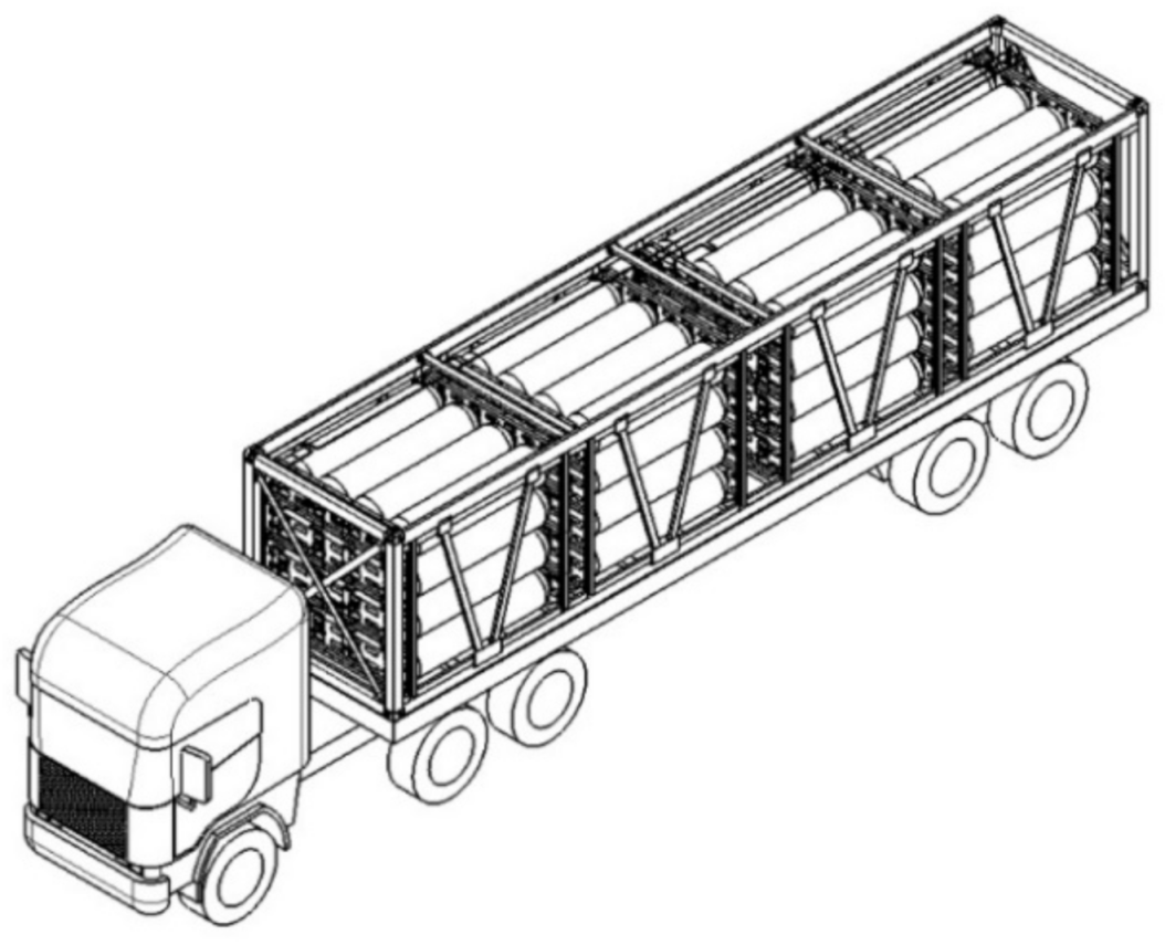
2.2. Hydrogen Tube Trailer Modeling

To perform the driving simulation of a hydrogen tube trailer, we constructed a full car model with a suspension system, steering system, and powertrain (driving shaft, wheels, and tires). The truck tractor shown in Figure 2 consists of the front suspension (leaf spring and cab suspension), rear suspension (tandem drive axle, drive wheel, and tires), powertrain, and steering. The truck trailer in Figure 2 includes a trailer suspension (trailer axle, trailer wheel, and tire), and a trailer body (tube skid trailer). The suspension and steering systems of the hydrogen tube trailer are typically used in common commercial trucks and the corresponding templates in MSC/Car Truck are utilized to describe them. The tube skid trailer was modeled as a flexible body to calculate the acceleration received by the structure during driving.
The model is composed of a vehicle (trailer) and a container loaded with skids by referring to the specifications of an actual in Table 1 to improve the accuracy.
The entire skid structure is made of ASTM A36 steel. The container-type skid structure is designed and manufactured according to ISO/TC 104 and Convention for Safe Containers (CSC) certification. As shown in Figure 3a, the container is a box-type structure (length 12,196 mm, width 2436 mm, and height 2591 mm) with V-shaped reinforcements for each section on the left and right sides of the longitudinal direction and X-shaped reinforcements in the front and back. The base frame is composed of rectangular tube-type bottom side rails and cross members which are welded together as sub-assembly and the roof frame is joined by three roof bows, a fixed frame, and a corner reinforcement plate. The skid structure is loaded with 64 hydrogen tubes and a pressure control valve and pipeline to transport compressed hydrogen. The partitions that hold the hydrogen tubes are composed of 4 extruded plates assembled with bolts, and two partitions are paired to fix the front and rear adapters of the tubes through a holder.
The hydrogen tubes are classified into Type 1 to Type 4 depending on the material, composition, and strength. Type 1 and 2 containers can store up to 150~300 bar, and Type 3 and 4 containers can store up to 350~700 bar. The hydrogen tubes loaded on the skid, in this study, were capable of storing and charging 700 bar using a Type 4 container.
As shown in Figure 3b, the modeling process was simplified by removing the pipelines and valves to facilitate the analysis process. All 64 hydrogen tubes were also removed to implement a method of applying the load to each bracket. The mesh quality was also improved by removing the rounded edge of each pipe that forms the skid structure.
The FE model used a 10-node tetrahedral element with a 25 mm size to perform the mesh. The total number of elements is 177,790 and the number of nodes is 633,825. The number of degrees of freedom is 1,901,475. The transient structural analysis according to dynamic load (acceleration) was carried out using an implicit time integration scheme. It took about 12 h of analysis time based on i7 Intel® CPU (3.8 GHz) 4 core (Intel Corp., Santa Clara, CA, USA) for each driving course.

2.3. Boundary and Hydrogen Tube Loading Conditions

Since the loading configuration of the skid structure on a trailer is a significant factor in the transfer of load, vibration, and shock, the constraints were implemented for the corner fitting areas on the 4 lower corners in the same way they are actually loaded. The boundary and loading conditions are shown in Figure 4. Figure 4 shows where the weight is applied, which is in the direction of gravity on the lower holder where the front and rear adapters of the hydrogen tube are fixed.
In terms of the hydrogen tubes that were removed to simplify the modeling process, in this study, we used a method of applying the weight of 16 hydrogen tubes (3520 kg) to the center of each section, as shown in Figure 5.

2.4. Driving Road Condition

The driving road conditions of the trailer were divided into 4 different driving courses. As shown in Figure 6, the driving courses included a flat course which had a normal flat road surface, a pothole course which had a depression in the road surface, and wave courses that drastically fluctuated due to different left and right ride heights. The wave courses were divided into a short- and long-wave courses according to the length of the wave. The road profiles represent scenarios in which the vehicle is traveling either on or off-road when a tire engages a pothole or bumps [23,24,25]. The driving simulations were performed on each course at 80 km/h speed.

3. Driving Simulation Results

3.1. Acceleration Results under Driving Simulation

In terms of the driving simulation results, in this study, we calculated the acceleration by the speed on each driving course. The acceleration was calculated at the corner fitting of the 4 lower corners where the vibration of the vehicle body is transmitted to the skid structure under boundary conditions. Figure 7 shows the name, driving direction, and the direction of acceleration of each measuring point corner.
The difference in the results of each axial acceleration calculated in the corner fitting areas (front right, front left, rear right, rear left) was within 2%. Figure 8 shows the results of acceleration over time at the rear left position of Figure 7.
Figure 8 shows the magnitude of acceleration at the rear left corner fitting when driving at a speed of 80 km/h on each course. The pothole course showed the greatest acceleration, where the acceleration in the Z-axis (height) direction was significantly larger than that of the other directions. In the short-wave course, the acceleration value in the Y-axis (width) direction increased significantly due to momentary left and right fluctuations by the trailer. In the long-wave course, the acceleration in the Y-axis (width) direction was stable and the magnitude of acceleration in the Z-axis (height) direction was also slow due to constant left and right fluctuations.

3.2. Structure Analysis Results Using Three-Axis Acceleration Values

In this study, a driving simulation was performed to evaluate the safety of a trailer skid structure loaded with a hydrogen tube against shock and vibration loads during driving according to road conditions. Three-axis acceleration values over time were calculated in four road conditions. For the driving simulation, the entire vehicle structure was used, and for the structural analysis, only the trailer structure was used.
For the structural analysis, the corner fitting regions of the structure were constrained. Regarding the load conditions, the weight of the hydrogen tube was implemented as shown in Figure 5 using the point mass, and the acceleration received by the structure during driving was input as shown in Figure 8.
Figure 9 and Figure 10 show the maximum deformation and von Mises stress results according to time.
The maximum deformation result shows a similar trend to the acceleration graph in Figure 8. In particular, in the case of the pothole course, the maximum deformation occurred at 3.05 mm, and the location was the front X-shaped reinforcements. For the short-wave and long-wave courses, the maximum deformations were 1.18 mm and 0.77 mm, respectively. The maximum deformation occurred in the same front X-shaped reinforcements as the pothole course, as shown in Figure 11. In the case of the flat course, the maximum deformation was 0.003 mm.
The value of maximum von Mises stress is related to the magnitude of the acceleration, but influenced more by the acceleration period (the time interval between the positive and negative peaks). On the one hand, in the case of the pothole course, the maximum acceleration was ±30 g, and the maximum von Mises stress obtained was 160.46 MPa. On the other hand, in the case of the short-wave course, the maximum von Mises stress obtained was 210.83 MPa, despite a maximum acceleration of ±10 g. In the case of the long-wave course with a maximum acceleration similar to the short-wave course, the maximum von Mises stress obtained was 52.10 MPa. This means that the maximum von Mises stress was highly correlated with the acceleration period. The period of the acceleration waveform in the short-wave course in Figure 8c was the shortest. The maximum von Mises stress occurred in the lower reinforcement U-beam fixing the bulkheads that loaded the hydrogen tubes, as shown in Figure 12. The maximum von Mises stress obtained on the flat course was 0.42 MPa.
The material of the skid was ASTM A36 steel, and the yield strength and ultimate tensile strength were 250 MPa and 400 MPa, respectively [26]. Table 2 summarizes the maximum von Mises stresses and material properties (yield and ultimate tensile strength) according to the road surface condition as a safety factor. The safety factors as compared with yield strength are all higher than 1 for the four driving road conditions. In general, only static loads are considered in a structural analysis at the design stage. However, there are no rules for dynamic loads. Thus, the reliability of the structure for further field tests was able to be secured, since the skid structure behaves within the elastic region when subjected to dynamic loads.

4. Conclusions

In general, only static loads are considered in a structural analysis at the design stage. The document in the Compressed Gas Association (CGA) TB-25: Design Considerations for Tube Trailers presents the static loading considerations. This document contains design criteria for mounting tubes to tube adapters and skid structures to withstand the total load, including tubes and adapters. In this study, in order to increase the reliability of the skid structure, the integrity of the structure was evaluated by considering the dynamic load received when driving on a special durable road. The dynamics of the driving trailer according to the irregularities of the road surface were obtained through multibody dynamic simulations considering the full car model equipped with 64 hydrogen tubes. The driving road conditions of the trailer were divided into four different driving courses, i.e., flat, pothole, short wave, and long wave. The road conditions utilized in this study were modeled using the special endurance roads of the actual driving test site (Korea Automobile Testing & Research Institute) specifications. Although there are various road conditions, the three road conditions considered in this study are most common on roads and have a significant influence on the integrity of a skid structure. The flat road was simulated as a reference to verify the trailer analysis model.
The transient structural analysis of the skid was performed by considering the resulting acceleration values at the corners of the skid as constraints. According to the comparison of the stress analysis results, we can conclude that the maximum von Mises stress is highly correlated with the acceleration period. It is considered that the sequential simulation process presented in this study could be widely applied to the structural safety assessment of a tube skid mounted on a trailer for hydrogen transportation in the early stage of design.

Author Contributions

Conceptualization, S.K. and H.-L.J.; methodology, S.K. and J.K.; software, H.K. (Hwanjin Kim), B.K., and K.C.; validation, S.K. and H.-L.J.; formal analysis, S.K.; investigation, S.K., J.J., and H.K. (Hwanjin Kim); resources, S.K. and B.K.; data curation, H.K. (Hwanjin Kim) and K.C.; writing—original draft preparation, S.K.; writing—review and editing, S.K. and H.-L.J.; visualization, S.K.; supervision, H.-L.J.; project administration, H.K. (Hyoungchan Kim); funding acquisition, H.-L.J. All authors have read and agreed to the published version of the manuscript.

Funding

This work was supported by the Technology Innovation Program (no. 20003058, Development of Hydrogen Gas Charging system for decreasing by half of FCEV Bus charging time and increasing two times of Hydrogen gas Tube Trailer transport capacity) funded by the Ministry of Trade, Industry and Energy (MOTIE, Korea).

Institutional Review Board Statement

Not applicable.

Informed Consent Statement

Not applicable.

Data Availability Statement

Not applicable.

Conflicts of Interest

The authors declare no conflict of interest.

References

  1. Moradi, R.; Groth, K.M. Hydrogen storage and delivery: Review of the state of the art technologies and risk and reliability analysis. Int. J. Hydrog. Energy 2019, 44, 12254–12269. [Google Scholar] [CrossRef]
  2. Gerboni, R.; Salvador, E. Hydrogen transportation systems: Elements of risk analysis. Energy 2009, 34, 2223–2229. [Google Scholar] [CrossRef]
  3. Han, S.M.; Hwang, B.C.; Kim, H.Y.; Kim, C. Analysis of the Autofrettage Effect in Improving the Fatigue Resistance of Automotive CNG Storage Vessels. Int. J. Precis. Eng. Manuf. 2009, 10, 15–21. [Google Scholar] [CrossRef]
  4. Son, D.S.; Hong, J.H.; Chang, S.H. Determination of the autofrettage pressure and estimation of material failures of a Type III hydrogen pressure vessel by using finite element analysis. Int. J. Hydrog. Energy 2012, 37, 12771–12781. [Google Scholar] [CrossRef]
  5. Marzbanrad, J.; Paykani, A.; Afkar, A.; Ghajar, M. Finite element analysis of composite high-pressure hydrogen storage vessels. J. Mater. Environ. Sci. 2013, 4, 63–74. [Google Scholar]
  6. Liu, P.F.; Chu, J.K.; Hou, S.J.; Xu, P.; Zheng, J.Y. Numerical simulation and optimal design for composite high-pressure hydrogen storage vessel: A review. Renew. Sustain. Energy Rev. 2012, 16, 1817–1827. [Google Scholar] [CrossRef]
  7. Han, M.G.; Chang, S.H. Failure analysis of a Type III hydrogen pressure vessel under impact loading induced by free fall. Compos. Struct. 2015, 127, 288–297. [Google Scholar] [CrossRef]
  8. Han, M.G.; Chang, S.H. Evaluation of structural integrity of Type-III hydrogen pressure vessel under low-velocity car-to-car collision using finite element analysis. Compos. Struct. 2016, 148, 198–206. [Google Scholar] [CrossRef]
  9. Kwak, H.S.; Kim, C. Structure integrity of rack module for compressed natural gas (CNG) pressure vessel—under automotive collision and vibration. J. Mech. Sci. Technol. 2016, 30, 5073–5081. [Google Scholar] [CrossRef]
  10. Park, E.J.; Nam, C.H.; Choi, S.J.; Kim, I.S.; Hwang, J.H. Structural Analysis of Skid for Hydrogen Transport with Arm-roll System. J. Korean Soc. Automot. Eng. 2019, 947–952. [Google Scholar]
  11. Kropáč, O.; Múčka, P. Effect of obstacles in the road profile on the dynamic response of a vehicle. Proc. Inst. Mech. Eng. Part D J. Automob. Eng. 2008, 222, 353–370. [Google Scholar] [CrossRef]
  12. Imine, H.; Delanne, Y.; M’sirdi, N.K. Road profile input estimation in vehicle dynamics simulation. Veh. Syst. Dyn. 2006, 44, 285–303. [Google Scholar] [CrossRef]
  13. Kansake, B.A.; Frimpong, S. Analytical modelling of dump truck tire dynamic response to haul road surface excitations. Int. J. Min. Reclam. Environ. 2020, 34, 1–18. [Google Scholar] [CrossRef]
  14. Kansake, B.A.; Frimpong, S.; Ali, D. Multi-body dynamic modelling of ultra-large dump truck-haul road interactions towards haul road design integrity. Int. J. Min. Reclam. Environ. 2020, 34, 649–671. [Google Scholar] [CrossRef]
  15. Pesterev, A.V.; Bergman, L.A.; Tan, C.A. A novel approach to the calculation of pothole-induced contact forces in MDOF vehicle models. J. Sound Vib. 2004, 275, 127–149. [Google Scholar] [CrossRef]
  16. Pesterev, A.V.; Bergman, L.A.; Tan, C.A. Pothole-induced contact forces in a simple vehicle model. J. Sound Vib. 2002, 256, 565–572. [Google Scholar] [CrossRef]
  17. Van Zeebroeck, M.; Lombaert, G.; Dintwa, E.; Ramon, H.; Degrande, G.; Tijskens, E. The simulation of the impact damage to fruit during the passage of a truck over a speed bump by means of the discrete element method. Biosyst. Eng. 2008, 101, 58–68. [Google Scholar] [CrossRef]
  18. Zhao, L.; Zhang, Y.; Yu, Y.; Zhou, C.; Li, X.; Li, H. Truck Handling Stability Simulation and Comparison of Taper-Leaf and Multi-Leaf Spring Suspensions with the Same Vertical Stiffness. Appl. Sci. 2020, 10, 1293. [Google Scholar] [CrossRef] [Green Version]
  19. Zhang, X.-Q.; Yang, B.; Yang, C.; Xu, G.-N. Research on ABS of multi-axle truck based on ADAMS/Car and Matlab/Simulink. Procedia Eng. 2012, 37, 120–124. [Google Scholar]
  20. Prado, M.; Cunha, R.; Neto, Á.; Costa, A.; D’Elboux, J.E. Bus handling validation and analysis using ADAMS/Car. In Proceedings of the 16th European ADAMS User Conference, Berchtesgaden, Germany, 14–15 November 2001. [Google Scholar]
  21. MSC. MSC Adams/Car Truck Help Document; MSC: San Diego, CA, USA, 2015; Available online: https://simcompanion.mscsoftware.com/infocenter/index?page=content&id=DOC10831&cat=1VMO50&actp=LIST (accessed on 18 January 2021).
  22. ANSYS Inc. ANSYS Mechanical User’s Guide Version 17.1; ANSYS Inc.: Canonsburg, PA, USA, 2016. [Google Scholar]
  23. Choi, S.; Park, J.; Jeon, K.; Yoo, Y.; Choi, G.; Park, T. A study on durability performance estimation for development of chassis corner module. Trans. Korean Soc. Automot. Eng. 2006, 14, 159–166. [Google Scholar]
  24. Chen, D.; Shahidi, B.; Stuhec, U.; Song, Y.; Chang, Y.P.; Palmer, T. Correlation of Explicit Finite Element Road Load Calculations for Vehicle Durability Simulations (No. 2006-01-1980); SAE Technical Paper; SAE International: Warrendale, PA, USA, 2006. [Google Scholar]
  25. Farrahi, G.H.; Khalaj, A. Estimation of fatigue damage caused by actual roads and maneuvers on proving ground. J. Achiev. Mater. Manuf. Eng. 2006, 14, 90–96. [Google Scholar]
  26. Troina, G.S.; Cunha, M.L.; Pinto, V.T.; Rocha, L.A.O.; Dos Santos, E.D.; Fragassa, C.; Isoldi, L.A. Computational Modeling and Design Constructal Theory Applied to the Geometric Optimization of Thin Steel Plates with Stiffeners Subjected to Uniform Transverse Load. Metals 2020, 10, 220. [Google Scholar] [CrossRef] [Green Version]
Figure 1. Hydrogen transport truck with tube skid trailer.
Applsci 11 03779 g001
Figure 2. Full car model of the hydrogen tube truck.
Applsci 11 03779 g002
Figure 3. Simplified tube skid design and dimensional information, (a) Skid with hydrogen tubes; (b) skid without hydrogen tubes.
Applsci 11 03779 g003
Figure 4. Boundary and loading conditions.
Applsci 11 03779 g004
Figure 5. Hydrogen tube weight condition using equivalent load. (a) Front view; (b) side view.
Applsci 11 03779 g005
Figure 6. Shape by driving course. (a) Flat course; (b) pothole course; (c) short-wave course; (d) long-wave course.
Applsci 11 03779 g006
Figure 7. Acceleration calculation points and driving direction.
Applsci 11 03779 g007
Figure 8. Acceleration calculation results according to time. (a) Flat course; (b) pothole course; (c) short-wave course; (d) long-wave course.
Applsci 11 03779 g008
Figure 9. Maximum deformation results according to time. (a) Flat course; (b) pothole course; (c) short-wave course; (d) long-wave course.
Applsci 11 03779 g009
Figure 10. The results for maximum von Mises stress according to time. (a) Flat course; (b) pothole course; (c) short-wave course; (d) long-wave course.
Applsci 11 03779 g010
Figure 11. Maximum deformation result under pothole course.
Applsci 11 03779 g011
Figure 12. Maximum deformation result under pothole course.
Applsci 11 03779 g012
Table 1. Main specification of the tube skid trailer.
Specification
Weight of truck tractor (kg)4000
Maximum payload (kg)27,000
Length (mm)12,915
Width (mm)2480
Height (mm)1470
Wheelbase (mm)10,100
Track (tread) (mm)1840
Tire type12R22.5-16PR(D)
Table 2. Safety factors according to the driving course.
Driving CourseMaximum Von Mises StressSafety Factor Compared to Yield StrengthSafety Factor Compared to
Ultimate Tensile Strength
Flat course0.42 MPa595.24952.38
Pothole course160.46 MPa1.562.49
Short-wave course210.83 MPa1.191.90
Long-wave course52.10 MPa4.807.68
Publisher’s Note: MDPI stays neutral with regard to jurisdictional claims in published maps and institutional affiliations.

