
Material Removal Model for Lapping Process Based on Spiral Groove Density


Abstract
:1. Introduction
2. Materials and Methods
2.1. Definition of Groove Density
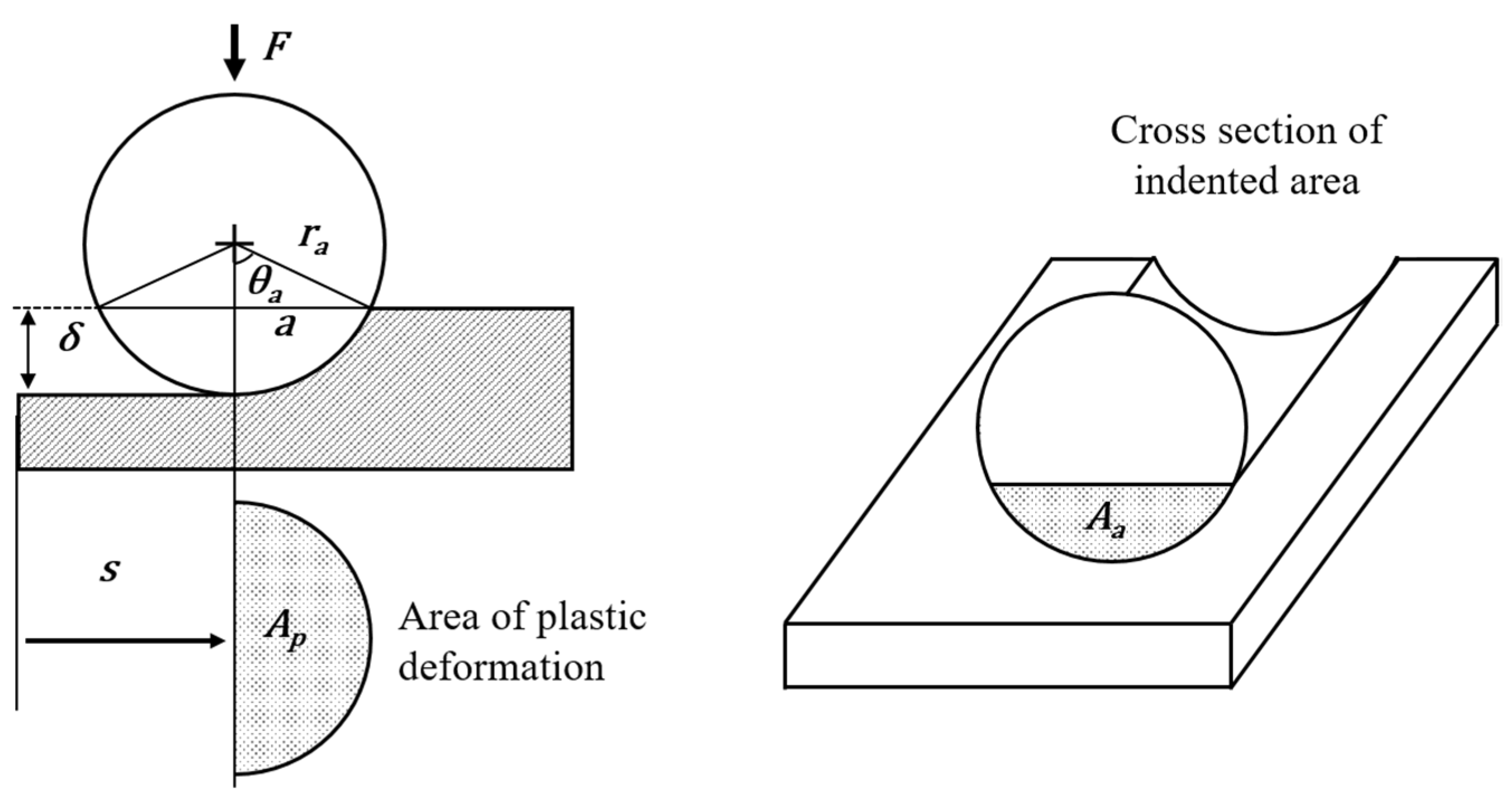
2.2. Material Removal Model according to Indentation Theory
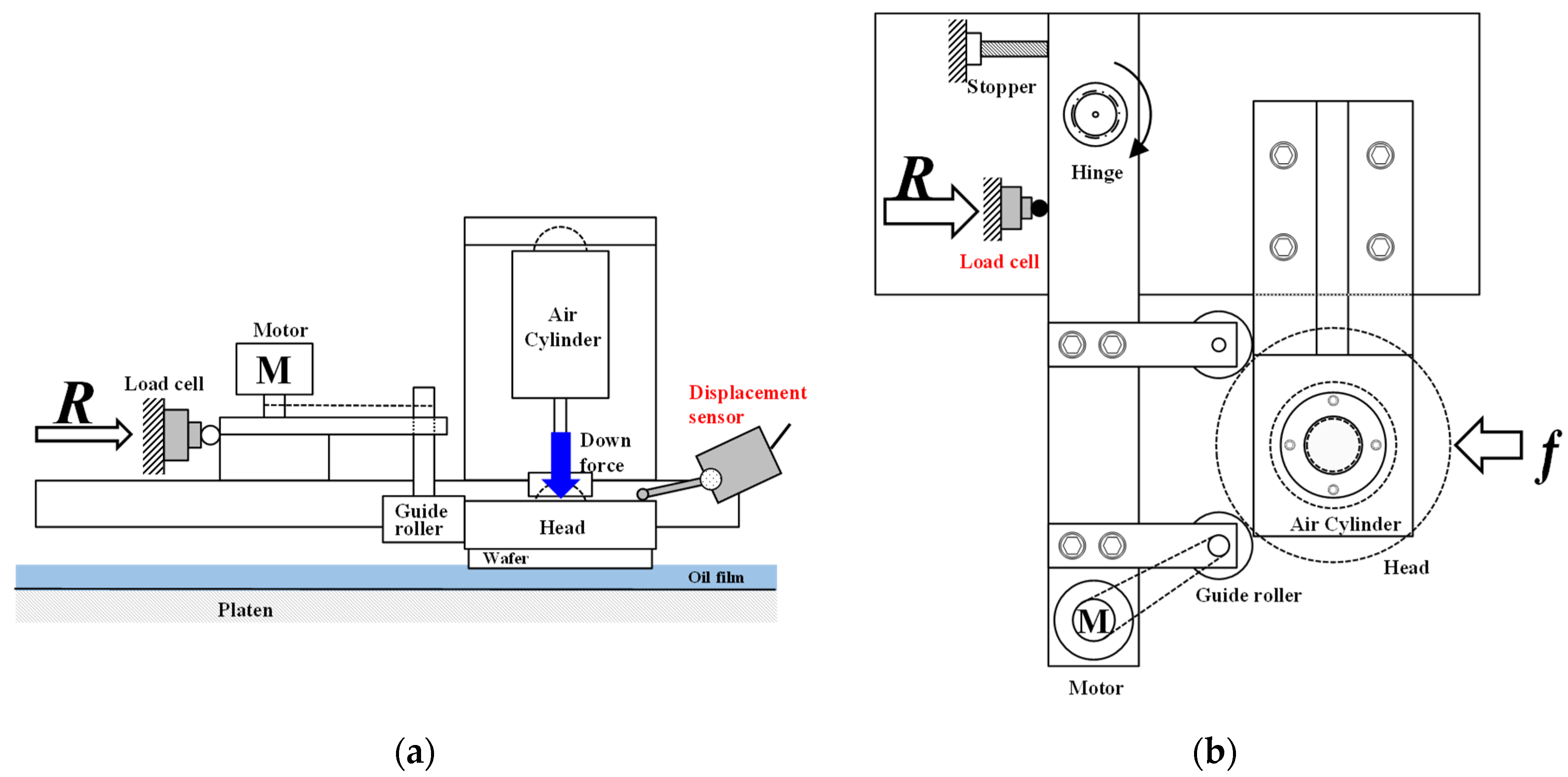
2.3. Experimental Equipment and Conditions
3. Experimental Results
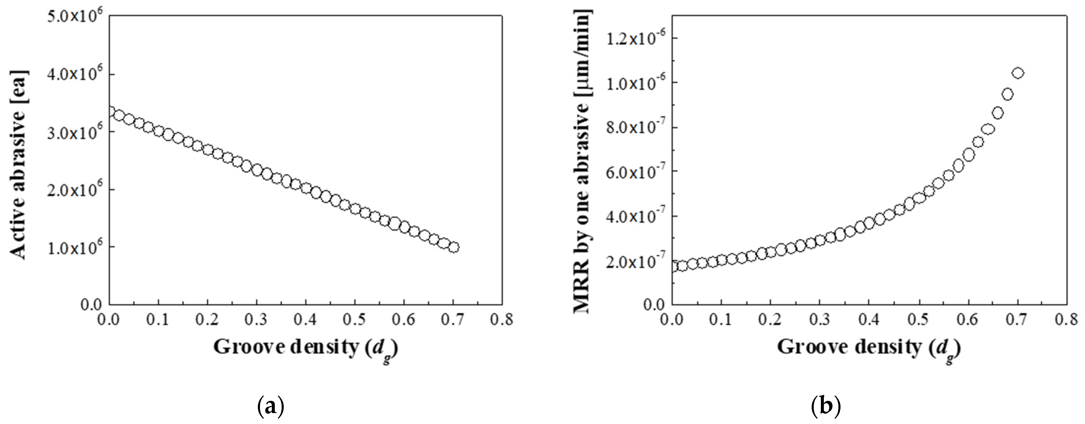
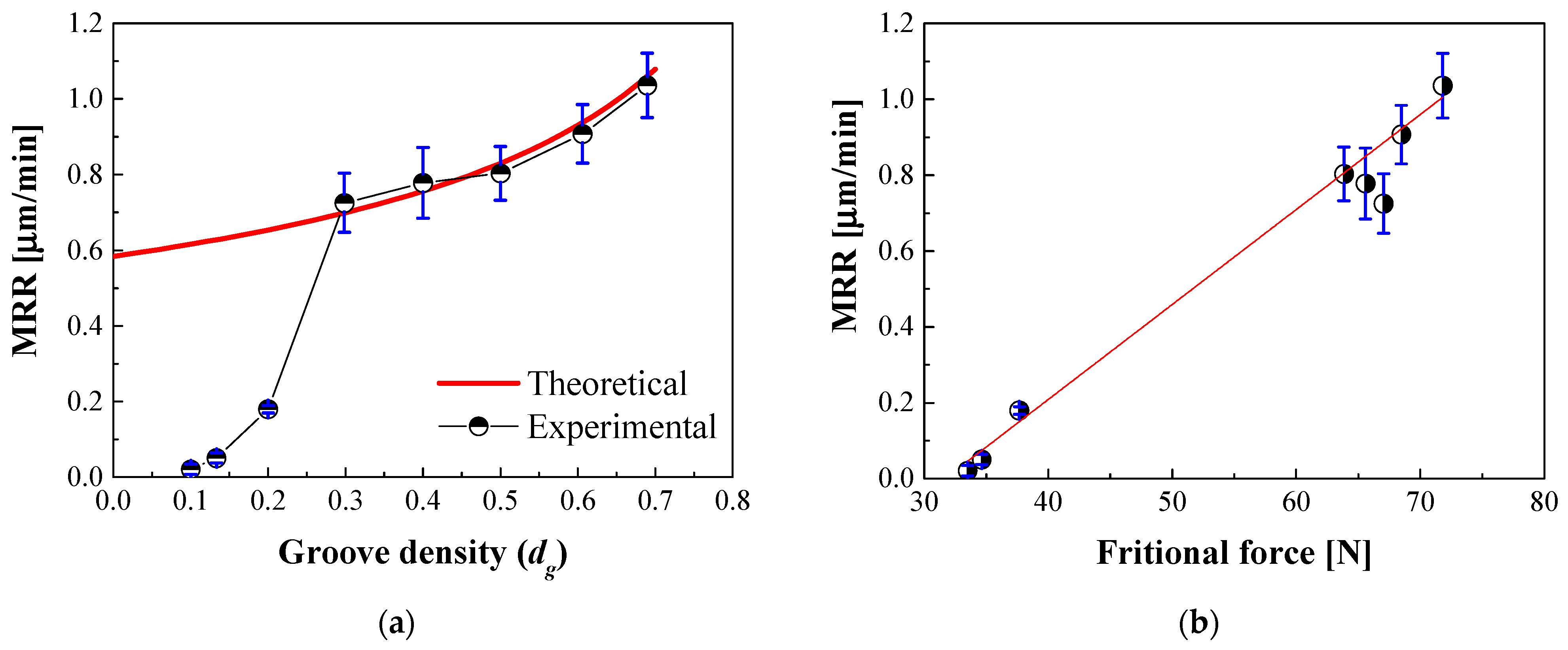
3.1. Material Removal Rate
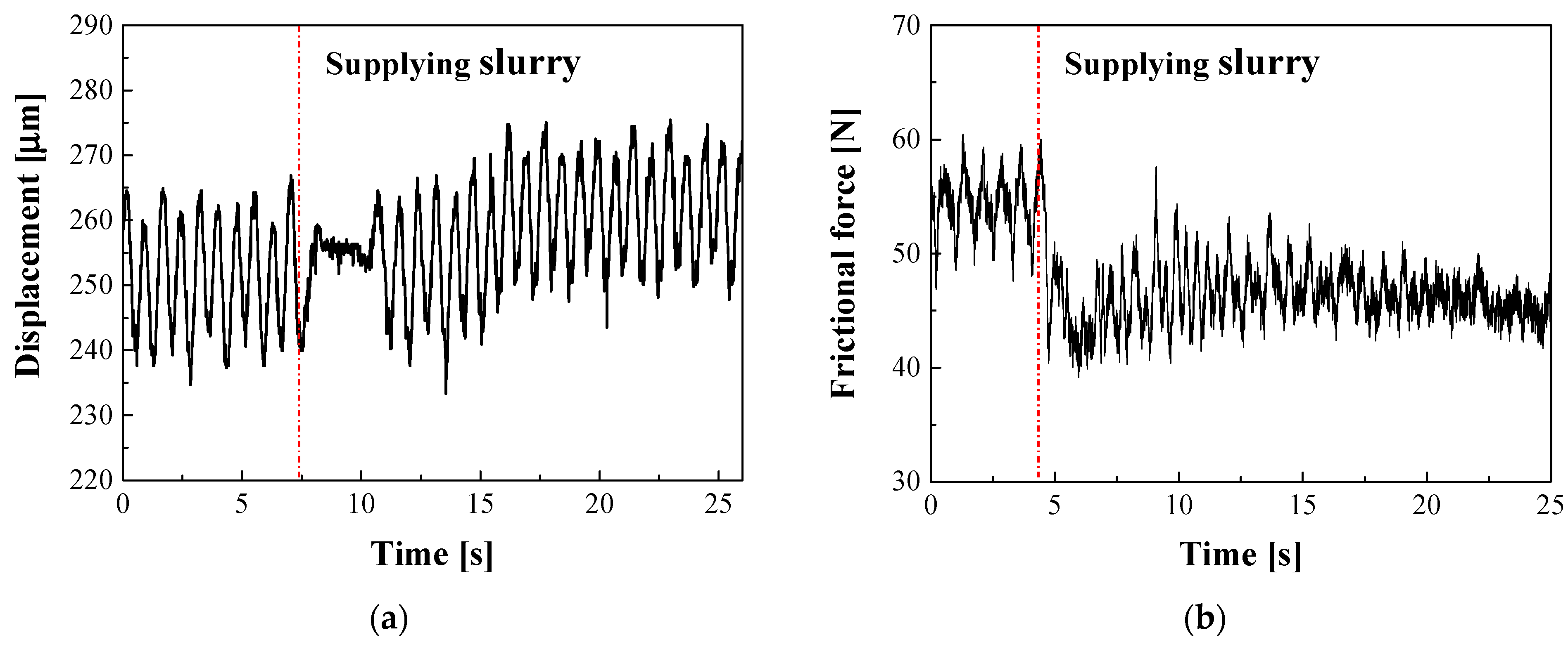
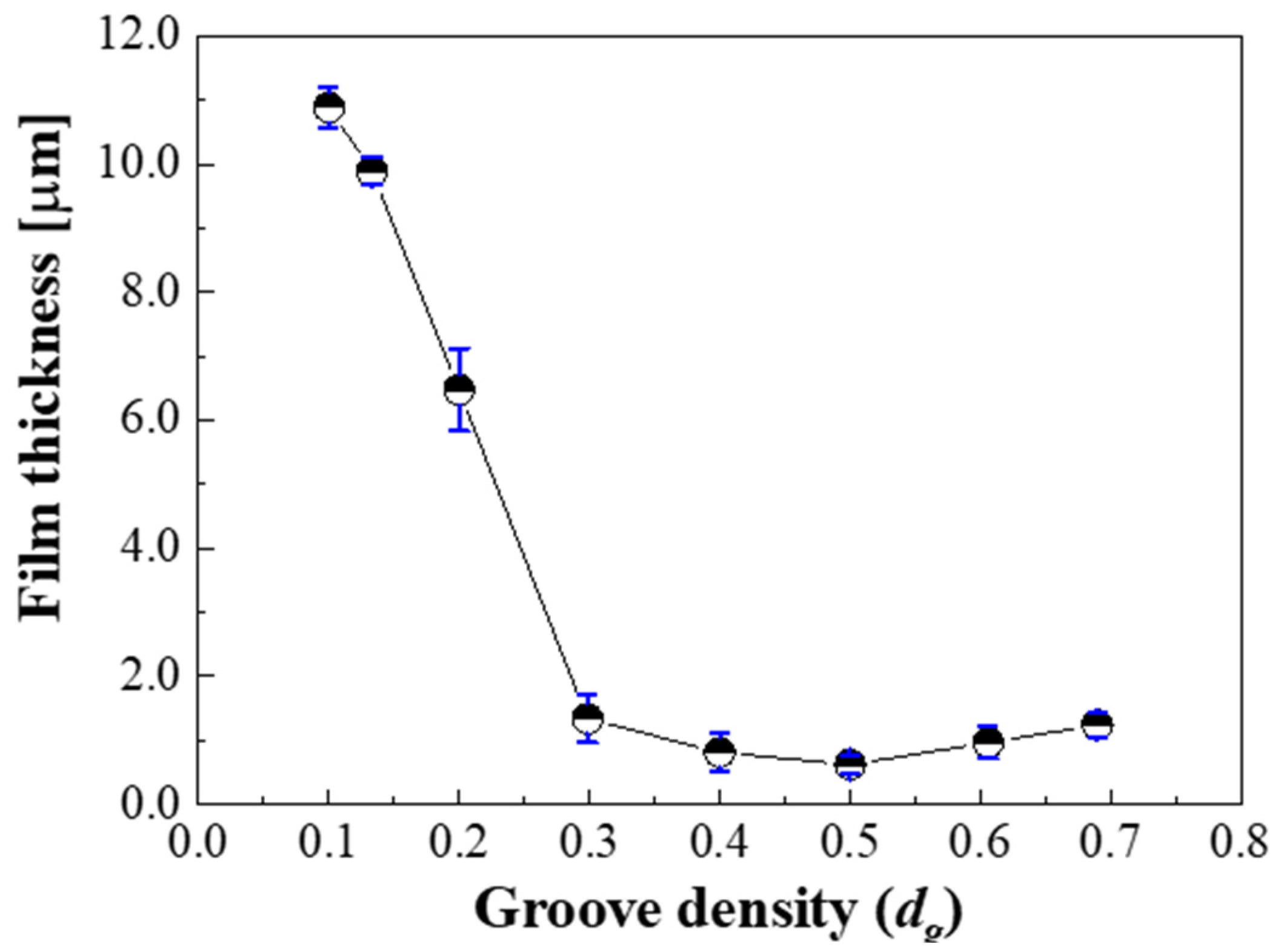
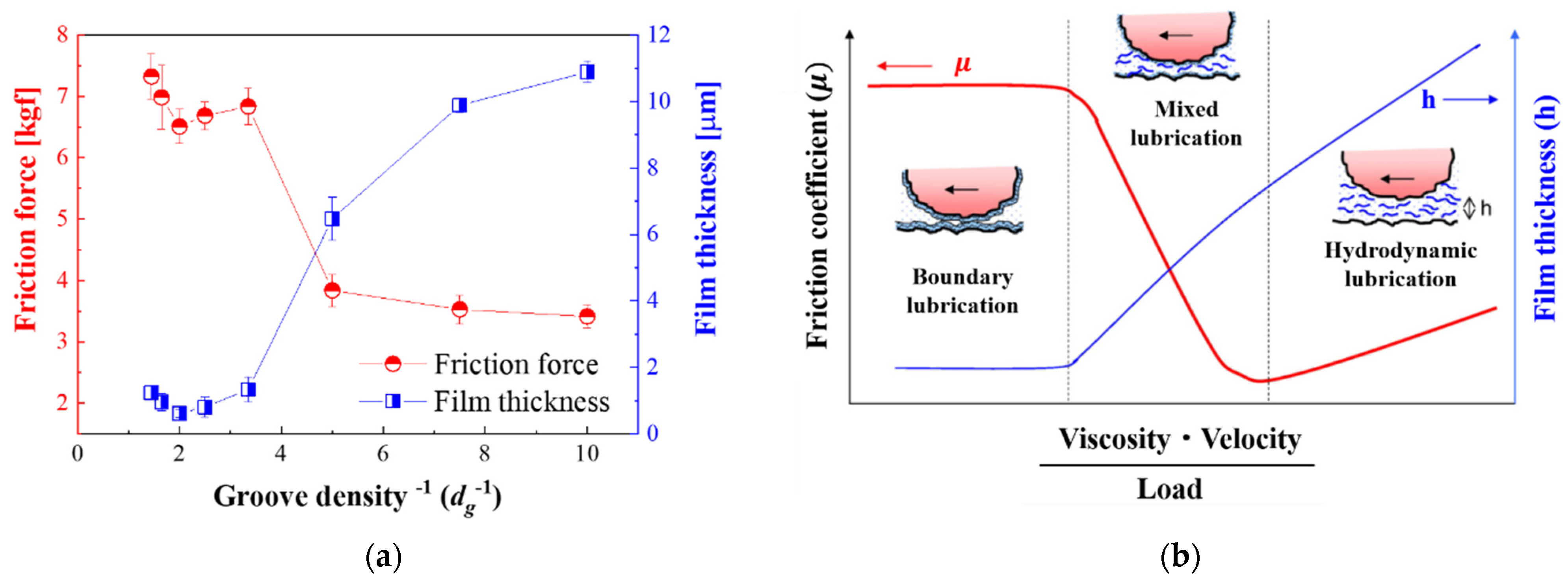
3.2. Oil Film Thickness and Frictional Force
4. Modified Material Removal Model
4.1. Solid–Solid Contact Theory
4.2. Material Removal Model Considering Oil Film Thickness
5. Conclusions
Author Contributions
Funding
Institutional Review Board Statement
Informed Consent Statement
Data Availability Statement
Conflicts of Interest
References
- Fang, H.S.; Zhang, Q.J.; Tian, J.; Wang, S.; Ma, R.H. Study of internal radiation with solute inclusions during Czochralski sapphire crystal growth. Int. J. Heat Mass Tran. 2014, 79, 783–789. [Google Scholar] [CrossRef]
- Tsai, M.Y.; Li, K.Y.; Ji, S.Y. Novel abrasive-impregnated pads and diamond plates for the grinding and lapping of single-crystal silicon carbide wafers. Appl. Sci. 2021, 11, 1783. [Google Scholar] [CrossRef]
- Jeong, S.; Jeong, K.; Choi, J.; Jeong, H. Analysis of correlation between pad temperature and asperity angle in chemical mechanical planarization. Appl. Sci. 2021, 11, 1507. [Google Scholar] [CrossRef]
- Li, Z.C.; Pei, Z.J.; Funkenbusch, P.D. Machining processes for sapphire wafers: A literature review. Proc. Inst. Mech. Eng. Part B J. Eng. Manuf. 2011, 225, 975–989. [Google Scholar] [CrossRef]
- Chen, C.C.A.; Li, J.C.; Liao, W.C.; Ciou, Y.J.; Chen, C.C. Dynamic pad surface metrology monitoring by swing-arm chromatic confocal system. Appl. Sci. 2021, 11, 179. [Google Scholar] [CrossRef]
- Su, J.X.; Liu, X.L.; Zhang, Z.Q.; Liu, Z.X. Influence of lapping parameters on 6H-SiC crystal substrate (0001) C surface based on diamond particle. Adv. Mater. Res. 2012, 565, 237–242. [Google Scholar] [CrossRef]
- Jo, H.; Lee, D.S.; Jeong, S.H.; Lee, H.S.; Jeong, H.D. Hybrid CMP slurry supply system using ionization and atomization. Appl. Sci. 2021, 11, 2217. [Google Scholar] [CrossRef]
- Touge, M.; Matsuo, T. Removal rate and surface roughness in high-precision lapping of Mn-Zn ferrite. CIRP Ann. 1996, 45, 307–310. [Google Scholar] [CrossRef]
- Fang, C.; Liu, C.; Zhao, Z.; Lin, Y.; Hu, Z.; Xu, X. Study on geometrical patterns of textured fixed-abrasive pads in sapphire lapping based on trajectory analysis. Prec. Eng. 2018, 53, 169–178. [Google Scholar] [CrossRef]
- Cho, B.J.; Kim, H.M.; Manivannan, R.; Moon, D.J.; Park, J.G. On the mechanism of material removal by fixed abrasive lapping of various glass substrates. Wear 2013, 302, 1334–1339. [Google Scholar] [CrossRef]
- Chang, Y.P.; Hashimura, M.; Dornfeld, D.A. An investigation of material removal mechanisms in lapping with grain size transition. J. Manuf. Sci. Eng. 2000, 122, 413–419. [Google Scholar] [CrossRef]
- Yuan, J.L.; Zhao, P.; Ruan, J.; Cao, Z.X.; Zhao, W.H.; Xing, T. Lapping and polishing process for obtaining super-smooth surfaces of quartz crystal. J. Mat. Proc. Tech. 2003, 138, 116–119. [Google Scholar] [CrossRef]
- Chen, C.C.A.; Tseng, C.H.; Tu, W.K. Friction force analysis on diamond lapping of sapphire wafers. Adv. Mat. Res. 2013, 797, 461–468. [Google Scholar]
- Tanaka, H.; Chiba, H.; Yoshikawa, T.; Iwatsuka, K.; Maeda, Y. Mechanical characterization of lapping plate materials in diamond charging process. Adv. Mat. Res. 2010, 126, 17–22. [Google Scholar] [CrossRef]
- Shi, F.G.; Zhao, B. Modeling of chemical-mechanical polishing with soft pads. Appl. Phys. A Mat. Sci. Proc. 1997, 67, 249–252. [Google Scholar] [CrossRef]
- Tseng, W.T.; Wang, Y.L. Re-examination of pressure and speed dependences of removal rate during chemical-mechanical polishing processes. J. Electrochem. Soc. 1997, 144, L15–L17. [Google Scholar] [CrossRef]
- Wei, C.C.; Horng, J.H.; Lee, A.C.; Lin, J.F. Analyses and experimental confirmation of removal performance of silicon oxide film in the chemical–mechanical polishing (CMP) process with pattern geometry of concentric groove pads. Wear 2011, 270, 172–180. [Google Scholar] [CrossRef]
- Guo, Y.; Lee, H.; Lee, Y.; Jeong, H. Effect of pad groove geometry on material removal characteristics in chemical mechanical polishing. Int. J. Prec. Eng. Manuf. 2012, 13, 303–306. [Google Scholar] [CrossRef]
- Rosales-Yeomans, D.; Lee, H.; Suzuki, T.; Philipossian, A. Effect of concentric slanted pad groove patterns flow during chemical mechanical planarization. Thin Solid Films 2012, 520, 2224–2232. [Google Scholar] [CrossRef]
- Kim, C.; Lee, G.J.; Rhee, C. Deaggregation and ultradispersion of detonation nanodiamonds in polar solvent using physicochemical treatments. J. Korean Powd. Met. Inst. 2013, 20, 479–486. [Google Scholar] [CrossRef] [Green Version]
- Yu, T.K.; Yu, C.C.; Orlowski, M. A statistical polishing pad model for chemical-mechanical polishing. In Proceedings of the IEEE International Electron Devices Meeting, Washington, DC, USA, 5–8 December 1993; pp. 865–868. [Google Scholar]
- Lee, H.; Kim, M.; Jeong, H. Effect of non-spherical colloidal silica particles on removal rate in oxide CMP. IJPEM 2015, 16, 2611–2616. [Google Scholar] [CrossRef]
- Das, B. Vicker’s hardness concept in the light of Vicker’s impression. Int. J. Rock Mech. Min. Sci. Geomech. Abstr. 1974, 11, 85–89. [Google Scholar] [CrossRef]
- Lu, J.; Rogers, C.; Manno, V.P.; Philipossian, A.; Anjur, S.; Moinpour, M. Measurements of slurry film thickness and wafer drag during CMP. J. Electrochem. Soc. 2004, 151, G241–G247. [Google Scholar] [CrossRef]
- Dwyer-Joyce, R.S.; Reddyhoff, T.; Zhu, J. Ultrasonic measurement for film thickness and solid contact in elastohydrodynamic lubrication. J. Tribo. 2011, 133, 031501. [Google Scholar] [CrossRef] [Green Version]
- Park, K.; Jung, J.; Lee, H.; Seo, H.; Jeong, S.; Lee, S.; Jeong, H. The effect of pad groove density on CMP characteristics. J. Korean Soc. Prec. Eng. 2005, 22, 27–33. [Google Scholar]
- Coles, J.M.; Chang, D.P.; Zauscher, S. Molecular mechanisms of aqueous boundary lubrication by mucinous glycoproteins. Curr. Opin. Colloid Interface Sci. 2010, 15, 406–416. [Google Scholar] [CrossRef]
- Kim, H.J. A Study on the Interfacial Characteristics and Its Effect on Material Removal in CMP. Ph.D. Thesis, Pusan National University, Busan, Korea, 2003. [Google Scholar]
- Greenwood, J.A.; Williamson, J.B.P. Contact of nominally flat surfaces. Proc. Math. Phys. Eng. Sci. 1966, 295, 300–319. [Google Scholar]
- Seok, J.; Sukam, C.P.; Kim, A.T.; Tichy, J.A.; Cale, T.S. Multiscale material removal modeling of chemical mechanical polishing. Wear 2003, 254, 307–320. [Google Scholar] [CrossRef]
- Qin, K.; Moudgil, B.; Park, C.W. A chemical mechanical polishing model incorporating both the chemical and mechanical effects. Thin Solid Films 2004, 446, 277–286. [Google Scholar] [CrossRef]
- Evans, C.J.; Paul, E.; Dornfeld, D.; Lucca, D.A.; Byrne, G.; Tricard, M.; Mullany, B.A. Material removal mechanisms in lapping and polishing. CIRP Ann. Manuf. Technol. 2003, 52, 611–633. [Google Scholar] [CrossRef] [Green Version]
- Thakurta, D.G.; Borst, C.L.; Schwendeman, D.W.; Gutmann, R.J.; Gill, W.N. Three-dimensional chemical mechanical planarization slurry flow model based on lubrication theory. J. Electrochem. Soc. 2001, 148, G207–G214. [Google Scholar] [CrossRef]
- Lee, T.; Jeong, H.; Lee, S.; Kim, D.; Kim, H. Effect of the lapping platen groove density on the characteristics of microabrasive-based lapping. Micromachines 2020, 11, 775. [Google Scholar] [CrossRef] [PubMed]


| Parameter | Condition | ||||||||
|---|---|---|---|---|---|---|---|---|---|
| Wafer | Sapphire, Φ100 mm | ||||||||
| Lapping plate | Copper resin, Φ300 mm | ||||||||
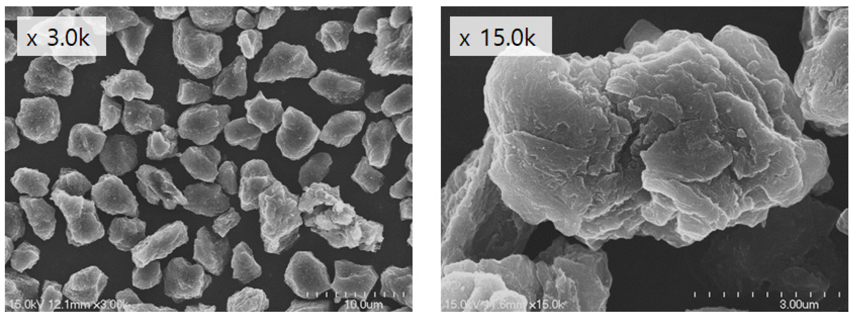
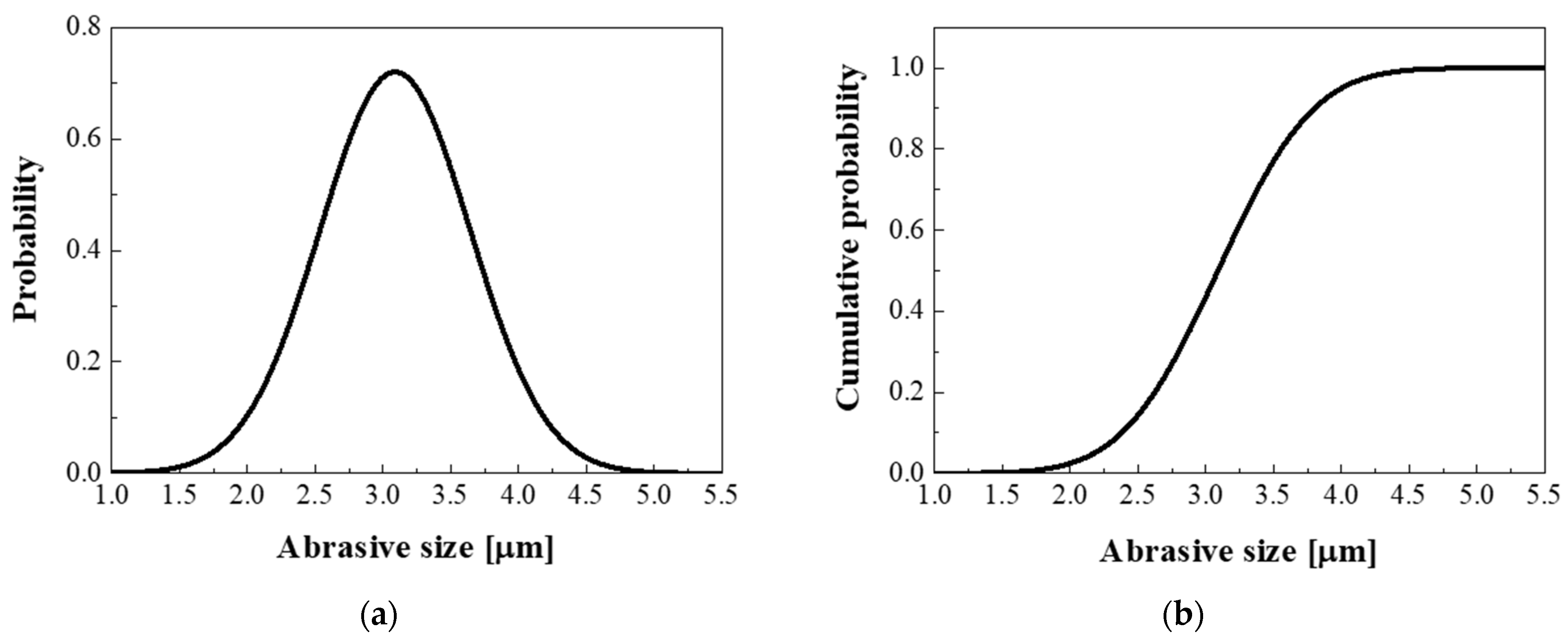
| Slurry | Polycrystalline diamond, average size 3.1 μm | ||||||||
| Flow rate | 4 mL/min | ||||||||
| Pressure | 400 gf/cm2 | ||||||||
| Velocity | 80 rpm | ||||||||
| Groove | Depth | 1.0 mm | |||||||
| Width | 2.0 mm | ||||||||
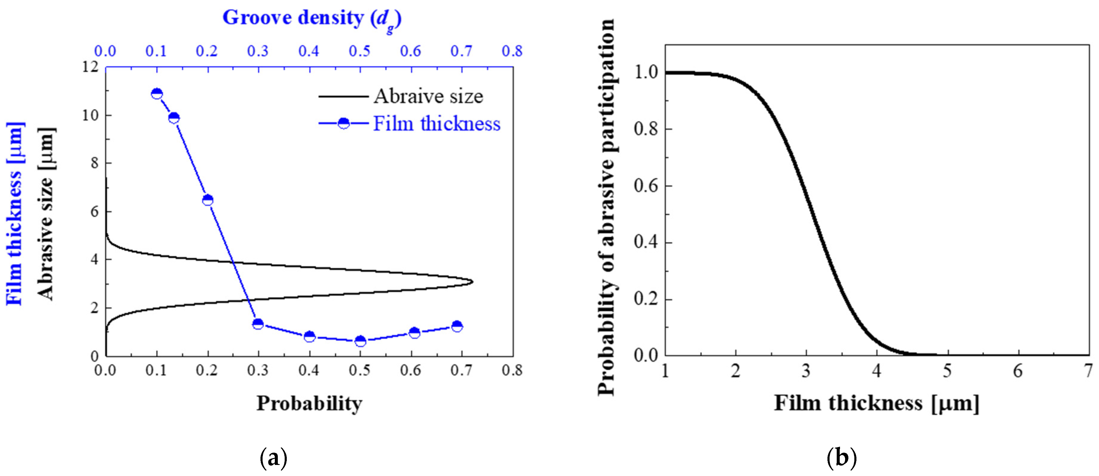
| Pitch [mm] | 20.0 | 15.0 | 10.0 | 6.7 | 5.0 | 4.0 | 3.3 | 2.9 | |
| Density (dg) | 0.10 | 0.13 | 0.20 | 0.30 | 0.40 | 0.50 | 0.61 | 0.69 | |
Publisher’s Note: MDPI stays neutral with regard to jurisdictional claims in published maps and institutional affiliations. |
© 2021 by the authors. Licensee MDPI, Basel, Switzerland. This article is an open access article distributed under the terms and conditions of the Creative Commons Attribution (CC BY) license (https://creativecommons.org/licenses/by/4.0/).
Share and Cite
Lee, T.; Jeong, H.; Lee, S.; Cho, H.; Kim, D.; Kim, H. Material Removal Model for Lapping Process Based on Spiral Groove Density. Appl. Sci. 2021, 11, 3950. https://doi.org/10.3390/app11093950
Lee T, Jeong H, Lee S, Cho H, Kim D, Kim H. Material Removal Model for Lapping Process Based on Spiral Groove Density. Applied Sciences. 2021; 11(9):3950. https://doi.org/10.3390/app11093950
Chicago/Turabian StyleLee, Taekyung, Haedo Jeong, Sangjik Lee, Hanchul Cho, Doyeon Kim, and Hyoungjae Kim. 2021. "Material Removal Model for Lapping Process Based on Spiral Groove Density" Applied Sciences 11, no. 9: 3950. https://doi.org/10.3390/app11093950