Article

Processing and Evaluation of a Carbon Fiber Reinforced Composite Bar Using a Closed Impregnation Pultrusion System with Improved Production Speed

1
Research Institute of Clean Manufacturing System, Korea Institute of Industrial Technology (KITECH), Cheonan 31056, Korea
2
School of Mechanical Engineering, Korea University of Technology and Education (KOREATECH), Cheonan 31253, Korea
*
Authors to whom correspondence should be addressed.
Appl. Sci. 2022, 12(10), 4906; https://doi.org/10.3390/app12104906
Submission received: 31 March 2022 / Revised: 7 May 2022 / Accepted: 11 May 2022 / Published: 12 May 2022

Abstract

:
In this paper, an epoxy resin-based carbon fiber reinforced composite (CFRP) bar pultrusion system using a closed impregnation device which has various advantages in process compared to traditional open bath type pultrusion system was developed, and the fiber impregnation system was improved through the analysis of resin properties for the high-speed production of CFRP bars used to support the mother glass in the display transfer cassettes. To improve the fiber feeder system, fiber guides were switched from perforated plates to roller guides for spreading fibers, which allowed the input fibers to be widened and flattened while reducing the fiber thickness. Additionally, the correlation between resin viscosity and impregnation speed were analyzed to evaluate the resulting mechanical properties at different pultrusion speeds and temperatures. A CFRP bar was produced with resin injection at room temperature and a pultrusion rate of 400 mm/min and compared to a CFRP bar produced with fiber spreading, a resin injection temperature of 40 °C, and a pultrusion rate of 600 mm/min; the latter with a 50% improved production rate showed improvements in mechanical properties, including the cross-sectional void by 98.7%, surface roughness by 75.5%, deflection by 34.9%, and bending strength by 70%.

1. Introduction

Carbon fiber is approximately 70% lighter, ten times stronger, and three times more elastic than iron, with superior durability, impact resistance, heat resistance, and wear resistance [1,2,3,4]. Carbon fiber reinforced polymer (CFRP) composites can reduce the weight of products and provide high stiffness; thus, their demand has been increasing in various industries, such as transportation vehicle parts, leisure sports products, semiconductor and display manufacturing processes, and more [5,6,7,8,9,10,11]. Among the composite molding methods that involve carbon fibers, pultrusion is the optimal process technology that can continuously produce CFRP of a uniform and simple cross-sectional shape and achieve a high automation rate with low investment costs [12,13,14]. In pultrusion, carbon fibers are stretched out while being impregnated with a mixed resin and hardener and are cured at both room temperature and high temperature to produce CFRP products [15].
Generally, the pultrusion processes that are most widely found in industry involve an open bath impregnation system, in which an open-top bath is completely filled with a mixed resin and hardener, and fibers are fed into the bath tank for impregnation with the resin [16,17]. The advantage of this open bath method is that a simple impregnation system can be used but the disadvantage is that management of the mixed solution is difficult. Particularly, whereas the variables in the impregnation stage of the pultrusion process include temperature, humidity, discharge rate, and more, the viscosity of the resin varies with temperature, and the resin properties also depend on exposure time to the external environment since penetration of impurities affects the curing time. Because the resin cannot be monitored during the composite production process, there may be defects that cause the final product to vary from the initial product, and it is difficult to analyze the causes of these defects during production. In addition, since the resin is exposed to the atmosphere, problems resulting from its volatility and toxicity should be carefully considered in terms of the safety of the working environment [18].
To address the disadvantages of the open impregnation device, a pultrusion system using a closed impregnation device was designed and fabricated in-house. In the fabricated system, the resin and hardener are stored separately inside the tank, and the temperature and humidity of the stored resin are managed. In addition, the system is economical because the temperature and amount of the discharged resin can be controlled to meet requirements. The resin is discharged in a sealed space, which eliminates the risk of toxic gas exposure and provides a comfortable work environment for operators. The entire system is fabricated such that it can be controlled with sensors, and the functionality and process of each step can be analyzed, enabling production for various applications with a variety of resins.
This study aims to improve the fiber impregnation system by using a closed impregnation device for pultrusion developed with in-house technology and ultimately produce high-quality CFRP with an improved speed by producing CFRP bars at various process parameters and analyzing their void fraction, surface roughness, and bending strength.

2. Materials and Methods

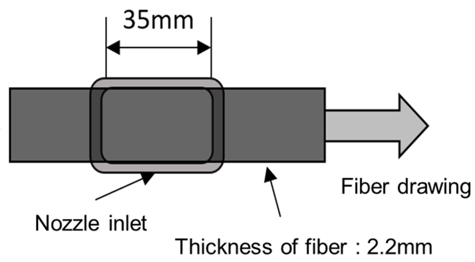
2.1. CFRP Bar Pultrusion System Using Closed Impregnation Device

To overcome the disadvantages of the open bath impregnation method, in which an impregnation tank exposed to the atmosphere is completely filled with a resin while fibers are passed through for impregnation, a closed impregnation method was used in this study. The process was improved because a specific amount of resin we designed was discharged into a closed mold which was sealed from the atmosphere. Figure 1 shows the pultrusion system using the closed impregnation device, which consists of the equipment monitoring system, resin management and discharge system, mixing head, closed impregnation device, curing device, pultrusion device, and cutting device. Unlike the conventional open bath method, there are separate tanks to manage the epoxy resin and hardener, and a stirrer is installed inside the tanks to mix the resin and hardener evenly. The temperature of each tank is managed and maintained by a control system. Furthermore, a flow rate system with precise control was designed and applied to discharge the resin at an accurate mixing ratio.
For the resin, a bisphenol-A type epoxy resin and a polyamine-based hardener with good workability from its low room-temperature viscosity were used. Using a mixing head injector, the equivalent weight of resin is mixed with the hardener and discharged into the impregnation device. Depending on the situation, the ratio between the resin and hardener can be adjusted in real time while preventing the external release of toxic gases and allowing the efficient consumption of the solution. In the closed impregnation device, the resin was injected into each of the four sides of specimen through a nozzle in the out-of-plane direction of the fibers for impregnation, and the inside of the mold was connected to a vacuum pump to maintain the vacuum. The resin injection pressure was designed to be controlled by a monitoring system (Figure 2a).
As shown in Figure 2b, the curing mold was placed right next to the impregnation device, and the insulation material was installed between the two so that they could be maintained at different temperatures. The curing mold was designed to manage the temperature profile with ten rod heaters in the machined holes located in upper and lower molds and five temperature sensors. Additionally, a cutter was placed at the end of the system to produce CFRP bars in the desired size. The CFRP bars were cured while passing through the curing mold of 140 °C at a constant speed, and in all cases, the post curing process was carried out at 45 °C for 40 min in the convection oven. The cross-sectional dimension of the CFRP bars prepared in this study is 40 mm wide, 10 mm high, and 2 mm thick.

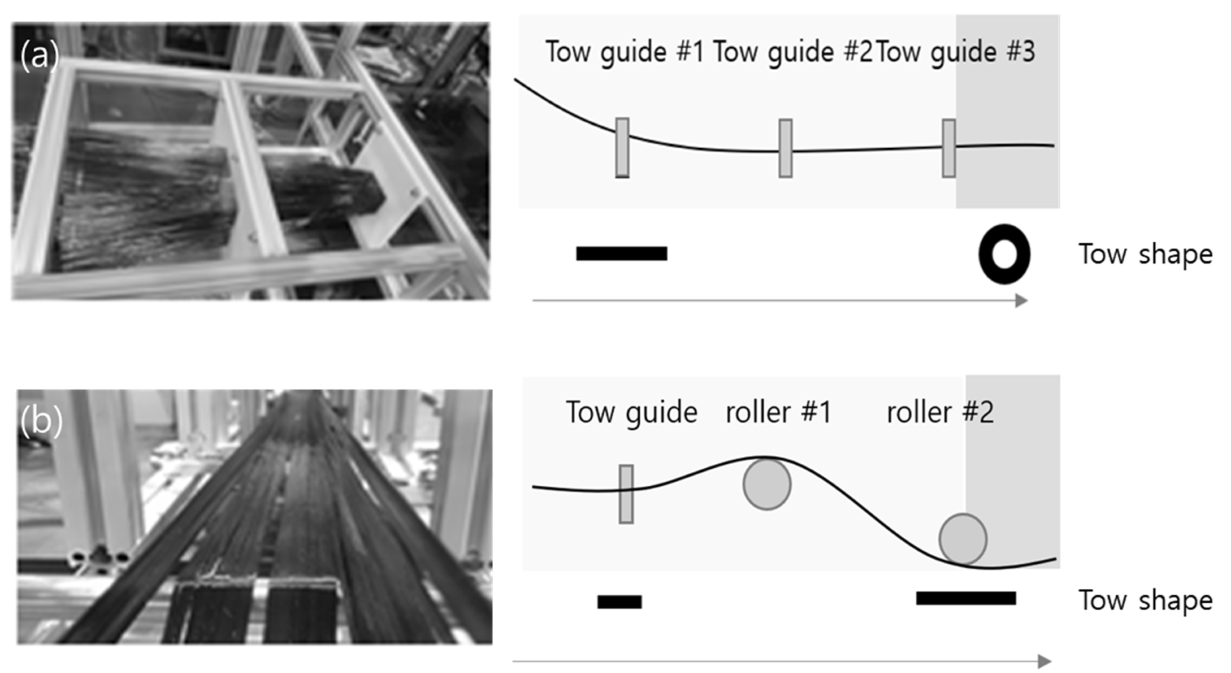
2.2. Improvement of Fiber Feeder System through Spreading

Approximately 126 strands of 24K tows are required to produce CFRP bars with a hollow rectangular cross-section of 40 × 10 × 2 mm. The arrangement of initially fed fibers is critical for forming this shape since bars cannot be produced in the desired shape with an uneven tow arrangement. An uneven fiber arrangement may produce a cross-section that is too thick on one side or bars with a rough surface. Dry fiber spreading is a method of widening and flattening fiber bundles by mechanically spreading them with several geometric rolls before the resin impregnation. This method employs either cylinder pins or a combination of geometric rolls, such as oval, angular, and cylinder. In the case of using only cylinder pins, previous studies show that the cylinder distance and height are variables of the fiber spreading [19,20,21]. S.D.R. Wilson identified that, as fibers were passed through cylinder rolls, the width of the fibers was dictated by the following relationship:
w = ( 12 A H ) 1 / 3
where w is the width of fibers, A is the cross-sectional area of fiber tows, and H is the height difference between fins [20].
In the conventional fiber feeder system with three guide parts, which prioritizes only the arrangement of the fibers, fibers are rolled up into a circular cross-section shape at the final guide, as shown in Figure 3a. Since the circular cross-section shape results in an uneven surface of CFRP bar, this system was improved by the following arrangement: the first guide holds the fibers, and the second and third roller guides spread the fibers while maintaining their arrangement, as shown in Figure 3b. The width of the 24K tow fibers is 7 mm, and roller guides are installed at intervals of 50 mm. Based on Equation (1), roller guides that were theoretically capable of spreading fibers from a width of 7 mm up to 34.7 mm were fabricated to maintain a constant surface evenness of the fibers entering the impregnation device.

2.3. Characterization Method

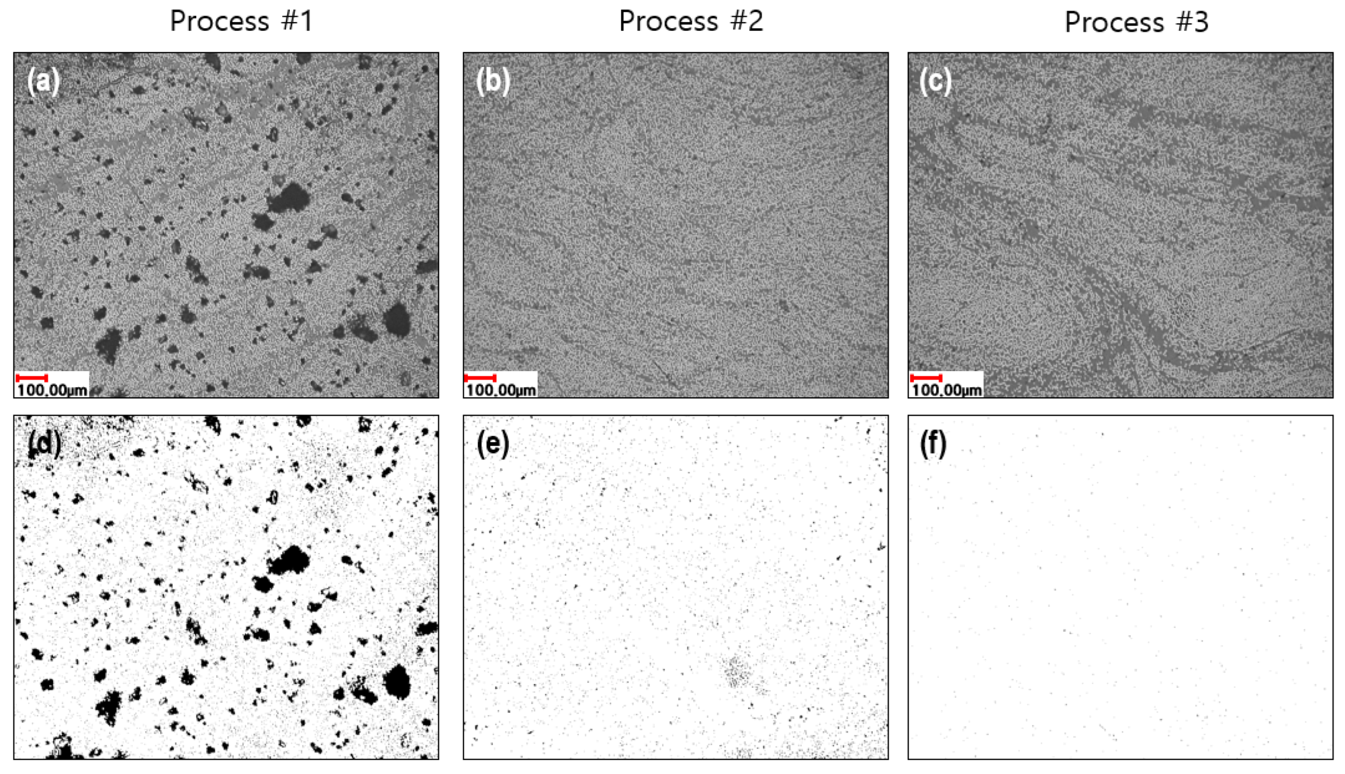
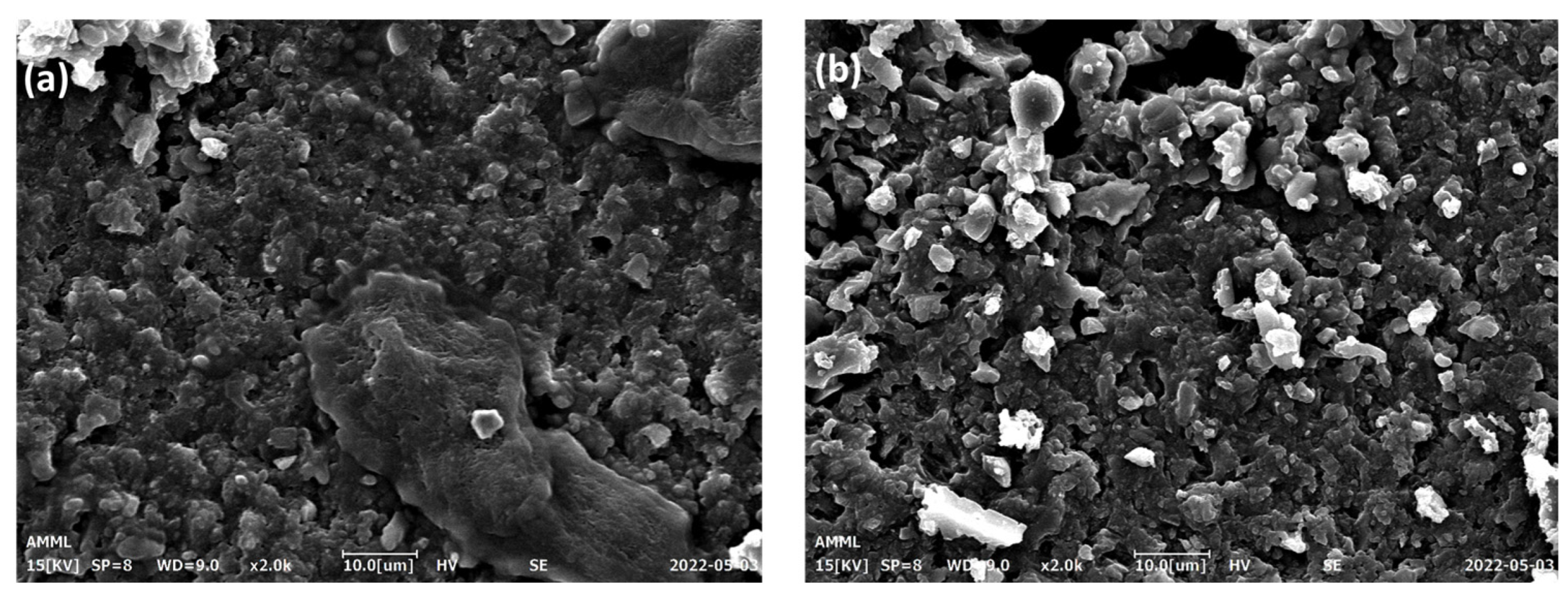
2.3.1. Void Fraction Analysis

Samples were prepared by polishing the cross-section of the CFRP bars produced in each process through pultrusion using the closed impregnation device. For void measurement with cross-sectional images, VK-X200 (Keyence Co., Ltd., Osaka, Japan) was used to acquire optical images, and the ImageJ program was used to analyze the images. In addition, a scanning electron microscope (SEM, EM-30N, Coxem Corp., Daejeon, Korea) was used for more precise measurement.

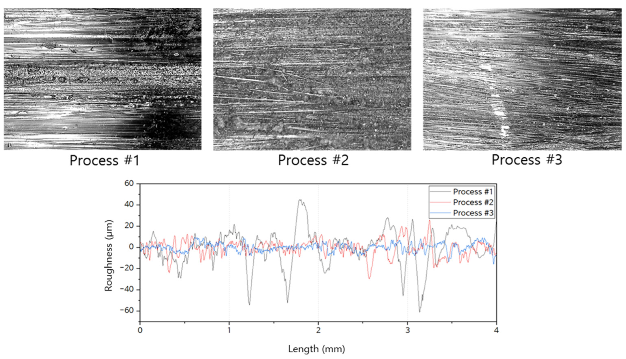
2.3.2. Measurement of Surface Roughness

Since the surface quality of CFRP is directly related to performance such as texture, quality, lifespan, and mechanical efficiency, it is important to evaluate the surface roughness of CFRP bars. The surface roughness of each specimen was measured by SJ-210 profilometer according to the ISO 1997 standard for arithmetic mean roughness, and the equipment was set to an R curve, Gaussian filter, and five measurement intervals. CFRP bars produced through pultrusion are arranged only in the longitudinal direction, so the surface roughness in the transverse direction which is expected to be rougher than longitudinal direction roughness was measured and used for the surface analysis of the bars.

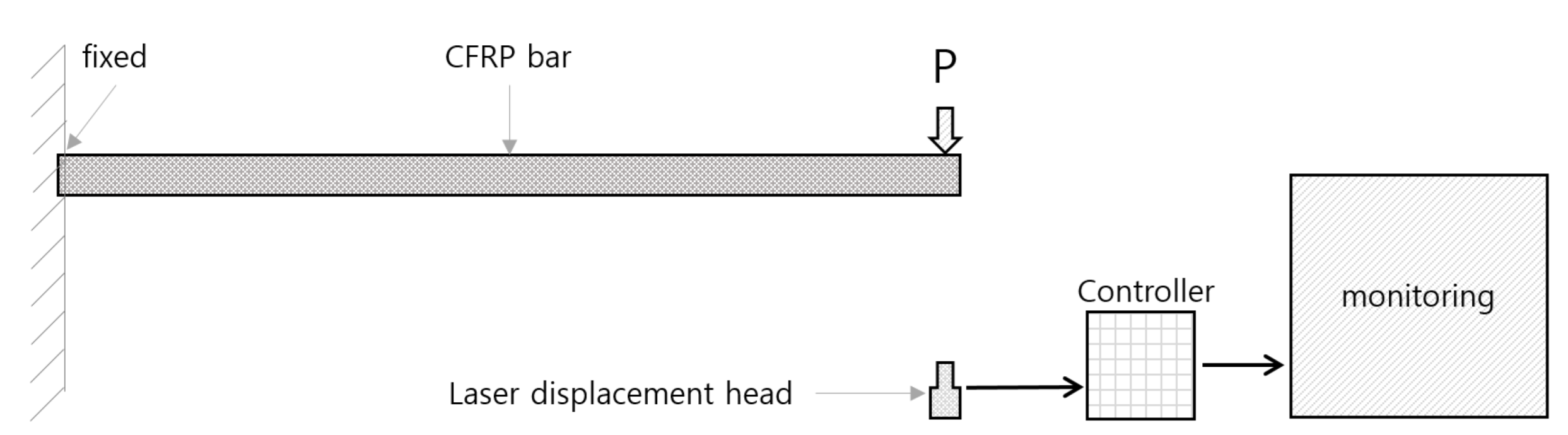
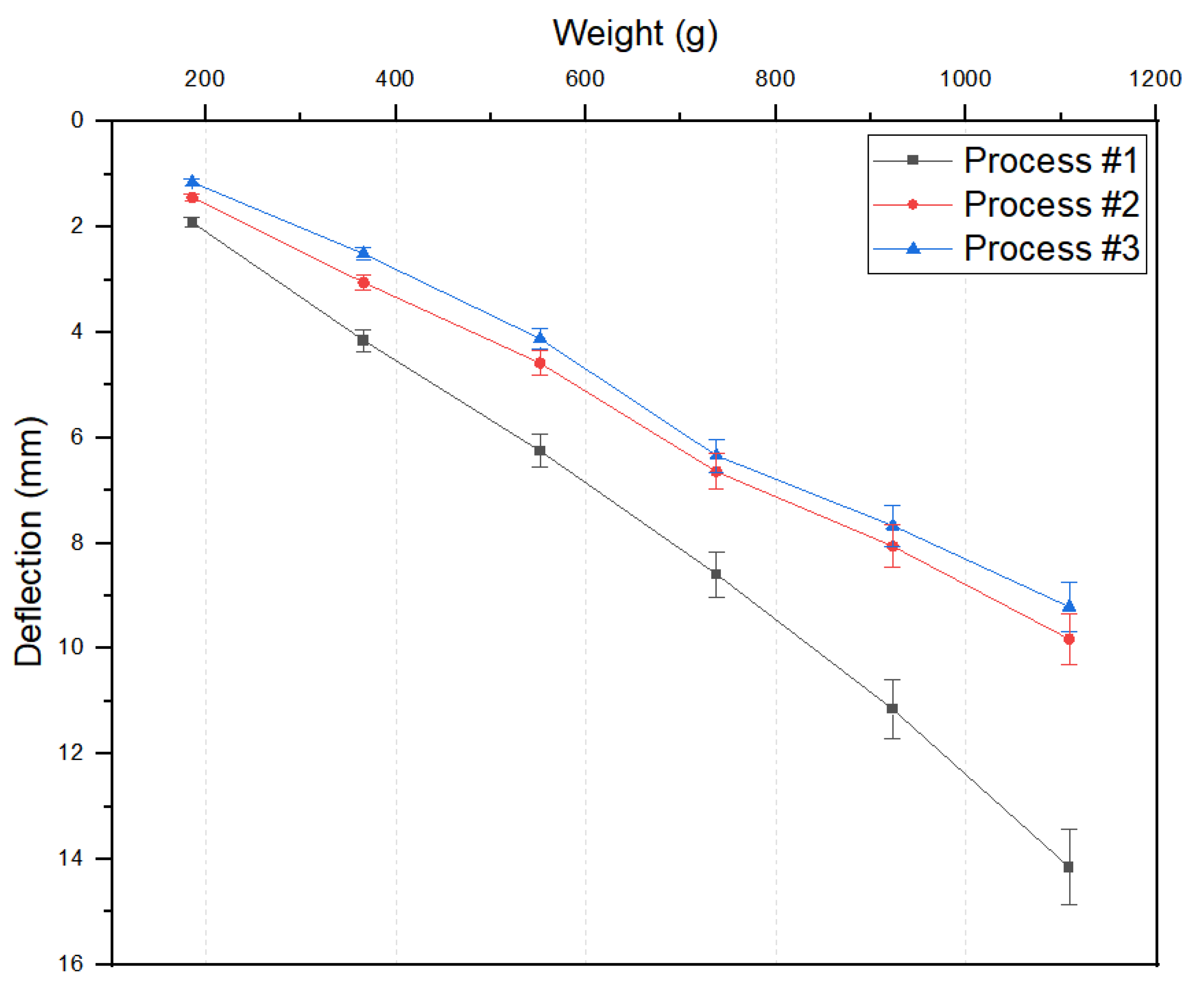
2.3.3. Cantilever Test and Three-Point Bending Test

As shown in Figure 4, one end of the cantilever was fixed in a test bench exclusively prepared for testing CFRP bars, whereas a weight was placed on the free end to apply a vertical load, and the deflection of the CFRP bars was measured using an LK-GD500 controller and LK-30 laser head (Keyence Co., Osaka, Japan). The samples used in the cantilever test were rectangular hollow shape (800 mm × 40 mm × 10 mm) with a thickness of 2 mm. In addition, a three-point bending strength test was performed in accordance with KS B 0804. Samples were prepared at 7 mm in width, 2 mm in thickness, and 25 mm in length, and the bending strength was measured by using cylindrical support with a radius, r, of 10 mm or greater, and applying a downward force from the top.

3. Results

3.1. Measurement of Resin Viscosity and Impregnation Behavior

To understand the effect of the resin injection temperature on viscosity, the viscosities of the resin, hardener, and mixed resin were measured using the LV2 spindle of the DV-II + Pro viscometer (Brookfield Co., Ltd., Sydney, Australia) depending on injection temperature, and the optimal resin injection temperature was determined to achieve the desired viscosity range (Table 1). In addition, Darcy’s law can be used to predict the rate at which the resin is impregnated between fibers. The relationship between the unsaturated permeability of fibers and the variables, such as the viscosity of the resin used, impregnation distance, time, and fiber volume fraction, was investigated by C. H. Park and P. Krawczak with the following equation [22]:
K u n s a t = l f 2 ( t ) 2 t μ · ( 1 V f ) P i n
where Kunsat is the unsaturated permeability of fibers, μ is the resin viscosity, lf(t) is the impregnation distance, t is the impregnation time, Vf is the volume fraction, and Pin is the injection pressure. The above equation can be used to predict the rate at which the resin is impregnated into dry-state fibers inside the closed impregnation system. Since the fibers are pultruded at a constant speed and the inlet length of the impregnation nozzle is 35 mm, as shown in Figure 5, the resin should be sufficiently impregnated in the fibers at the given speed, or within the given impregnation time, even if the pultrusion speed is increased. In this impregnation system, the thickness of the fibers that should be impregnated is approximately 2.2 mm, which is 10% thicker than the final bars produced with the fiber volume fraction of 60%. Therefore, the process time was predicted based on the permeability of the fiber with a volume fraction of 55%. Through this analysis, it is possible to specify the required resin viscosity or the required process temperature according to the given pultrusion speed. Additionally, for experimental accuracy, the temperature of the resin storage tank as well as that of the pipe were controlled to maintain a constant temperature during the resin discharge and impregnation.
To predict the impregnation speed, the out-of-plane fiber permeability depending on the fiber volume content was based on the experimental result reported by David Becker et al., who used a similar fiber type, resin injection pressure, and fiber volume fraction. In this study, when the fiber volume fraction was 50%, the out-of-plane fiber permeability was measured to be 1.13 × 10⁻¹² [23].
Since the impregnation time is determined by the above-mentioned unsaturated permeability in the out-of-plane direction, the length of resin inlet, and the pultrusion speed, the impregnation time at a given pultrusion speed was substituted into Equation (2) to calculate the resin viscosity required for the impregnation thickness of 2.2 mm, as shown in Table 2 below.
The required viscosity of the mixed resin was found to decrease as the pultrusion speed increased, and a mixed resin viscosity of 368 mPa·s or lower was necessary to impregnate the fibers with a thickness of 2.2 mm at the improved speed of 600 mm/min. As shown in Table 1, the viscosity of the mixed resin was 220.4 mPa·s at 40 °C, and therefore, it appears that the resin can be sufficiently impregnated in the fibers at a pultrusion speed of 600 mm/min if the temperature of the closed impregnation system is maintained at 40 °C. Figure 6 shows the changes in the viscosity depending on the temperature and the changes in the required viscosity depending on the pultrusion speed. The resin viscosity required for sufficient impregnation at the pultrusion speeds of 400 and 600 mm/min was identified and used to set the process temperature.

3.2. Evaluation of CFRP Bar by Different Process Parameters

CFRP products were produced through pultrusion using the closed impregnation device with the resin temperature, pultrusion speed, and applicability of fiber spreading as process variables, and various physical properties were evaluated by collecting samples from the same location in each process. The pultrusion speed of 400 mm/min in Process #1 with the resin injected at room temperature was increased to 600 mm/min for Processes #2 and #3 to examine the effect of improving the process by spreading the fibers and increasing the impregnation temperature (Table 3). Particularly, only the impregnation temperature was varied in Processes #2 and #3 to experimentally confirm the viscosity analysis results in Section 3.1.

3.2.1. Void Fraction

As shown in Figure 7, cross-section images measured by optical microscope are shown in (a) to (c), and void fraction analysis images are shown in (d) to (f) for each process. In the void fraction analysis images, the black portion indicates the void in the overall area. The void fraction relative to the entire imaged area of the CFRP bar produced in Process #1 was found to be 9.595%, and it was significantly reduced in Processes #2 and #3 at 1.408% and 0.122%, respectively, which could be attributed to the effective fiber impregnation. In addition, for precise comparison of processes #2 and #3, the cross-section of each specimen was measured by SEM, and the results are shown in Figure 8. Unlike Figure 8a, Figure 8b shows the void around the fibers due to the poor impregnation.

3.2.2. Surface Roughness

Figure 9 and Table 4 show the result of measuring the surface roughness of the CFRP bar produced in each process. The maximum transverse Ra measurement for the CFRP bars produced in processes #1, #2, and #3 was 12.78, 5.90, and 3.13 μm, respectively, indicating that the surface roughness was improved by 53.8% and 75.5% in processes #2 and #3 compared to process #1. Moreover, compared to process #2, the surface roughness was improved by 47% in process #1. These results were consistent with the impregnation behavior in Section 3.2.1, and showed that the surface unevenness of the fibers was smaller in processes #2 and #3 due to the effect of fiber spreading compared to Process #1 without fiber spreading.

3.2.3. Bending Properties

Table 5 and Figure 10 show the cantilever test results, illustrating the deflection level as a function of the weight in each process. The result indicated that the deflection in processes #2 and #3 was improved by 30.6% and 34.9%, respectively, compared to process #1, exhibiting the same trend as the previous results. In addition, a three-point bending strength test was performed. In each case, the maximum bending strength was measured and shown in Table 6. The bending test results indicated that the bending strength in processes #2 and #3 was improved by 132% and 180%, respectively, compared to process #1.

4. Conclusions

In this study, CFRP bar pultrusion process conditions were improved using a closed impregnation device, and the void fraction, surface roughness, deflection characteristics, and bending strength of the produced CFRP bars were evaluated. CFRP bars were produced and evaluated under three processes of different resin impregnation temperatures (20 °C, 30 °C, and 40 °C), pultrusion speeds (400 and 600 mm/min), and with and without the fiber spreading process. The possibility of manufacturing CFRP bars at a higher pultrusion speed by increasing the impregnation temperature and spreading fibers was confirmed by comparing Processes #2 and #3 to Process #1. In addition, the effect of increasing the impregnation temperature, as analyzed in Section 3.1, was confirmed by comparing Processes #2 and #3. The evaluation results for each process are summarized in Table 7.
The lower the void fraction, surface roughness, and deflection, and the higher the bending strength, the higher the quality of the CFRP bar with effective impregnation. Throughout the evaluations, processes #2 and #3 achieved effective resin impregnation in the fibers due to increased impregnation temperature and the effect of fiber spreading, and the resulting CFRP bars were of a higher quality compared to process #1. In particular, for the surface of CFRP bars to be even, not only does the resin have to be well impregnated in the fibers but also the deviation in thickness of the fed fibers must be small. Therefore, the noticeable improvement in processes #2 and #3 compared to process #1 in the surface roughness evaluation appears to be the result of the effect of fiber spreading in addition to the increased impregnation temperature. Furthermore, the comparison between processes #2 and #3 verified the effect of the impregnation temperature. Based on the initial analysis result, the viscosity of the mixed resin must be 368 mPa·s or less for complete impregnation at a pultrusion speed of 600 mm/min, but the viscosity of the mixed resin at 30 °C was higher at 466 mPa·s, which resulted in a CFRP bar with a relatively lower quality compared to the result at 40 °C. This indicates that the impregnation temperature is directly related to the degree of resin impregnation in pultrusion, greatly affecting the quality of the final product. Since the CFRP bars produced in this study are used as a component for supporting the display mother glass in cassettes, the deflection and bending strength of the bars are the most important values among the physical properties, meanwhile, the pultrusion speed is imperative for reducing production costs. As a result, CFRP bars with enhanced deflection and bending strength by up to 34.9% and 70%, respectively, were produced by improving the process variables, and at the same time, the pultrusion speed was increased by approximately 50% from the typical speed of 300–400 to 600 mm/min.

Author Contributions

Conceptualization, B.K. and C.L.; methodology, B.K.; validation, B.K., C.L. and H.-M.Y.; formal analysis, S.-M.K.; investigation, S.-M.K. and H.-M.Y.; resources, H.-M.Y.; data curation, B.K.; writing—original draft preparation, B.K.; writing—review and editing, B.K., S.-M.K. and H.-M.Y.; visualization, B.K.; supervision, S.-M.K. and H.-M.Y.; project administration, S.-M.K. and H.-M.Y.; funding acquisition, H.-M.Y. All authors have read and agreed to the published version of the manuscript.

Funding

This paper was supported by Education and Research promotion program of KOREATECH in 2021, the National Research Foundation of Korea (NRF) grant funded by the Korea government (MSIT) (No. NRF-2021R1G1A1006606) and “Regional Innovation Strategy (RIS)” through the National Research Foundation of Korea (NRF) funded by the Ministry of Education (MOE) (2021RIS-004).

Data Availability Statement

Not applicable.

Conflicts of Interest

The authors declare no conflict of interest.

References

  1. Krenkel, W. Carbon Fiber Reinforced CMC for High-Performance Structures. Int. J. Appl. Ceram. Technol. 2004, 1, 188–200. [Google Scholar] [CrossRef]
  2. Gohardani, O.; Elola, M.C.; Elizetxea, C. Potential and prospective implementation of carbon nanotubes on next generation aircraft and space vehicles: A review of current and expected applications in aerospace sciences. Prog. Aerosp. Sci. 2014, 70, 42–68. [Google Scholar] [CrossRef]
  3. Hsissou, R.; Seghiri, R.; Benzekri, Z.; Hilali, M.; Rafik, M.; Elharfi, A. Polymer composite materials: A comprehensive review. Compos. Struct. 2021, 262, 113640. [Google Scholar] [CrossRef]
  4. Mallick, P.K. Advanced materials for automotive applications: An overview. Adv. Mater. Automot. Eng. 2012, 5–27. [Google Scholar] [CrossRef]
  5. Stewart, R. Carbon fibre composites poised for dramatic growth. Reinf. Plast. 2009, 53, 16–21. [Google Scholar] [CrossRef]
  6. Forintos, N.; Czigany, T. Multifunctional application of carbon fiber reinforced polymer composites: Electrical properties of the reinforcing carbon fibers—A short review. Compos. Part B Eng. 2019, 162, 331–343. [Google Scholar] [CrossRef]
  7. Witik, R.A.; Teuscher, R.; Michaud, V.; Ludwig, C.; Månson, J.-A.E. Carbon fibre reinforced composite waste: An environmental assessment of recycling, energy recovery and landfilling. Compos. Part A Appl. Sci. Manuf. 2013, 49, 89–99. [Google Scholar] [CrossRef]
  8. Friedrich, K.; Almajid, A.A. Manufacturing Aspects of Advanced Polymer Composites for Automotive Applications. Appl. Compos. Mater. 2013, 20, 107–128. [Google Scholar] [CrossRef]
  9. Jang, B.Z. Advanced Polymer Composites: Principles and Applications; ASM International: Materials Park, OH, USA, 1994. [Google Scholar]
  10. Zhang, J.; Chevali, V.S.; Wang, H.; Wang, C.-H. Current status of carbon fibre and carbon fibre composites recycling. Compos. Part B Eng. 2020, 193, 108053. [Google Scholar] [CrossRef]
  11. Qureshi, J. A Review of Fibre Reinforced Polymer Structures. Fibers 2022, 10, 27. [Google Scholar] [CrossRef]
  12. Liu, T.Q.; Xing, L.; Peng, F. A comprehensive review on mechanical properties of pultruded FRP composites subjected to long-term environmental effects. Compos. Part B Eng. 2020, 191, 107958. [Google Scholar] [CrossRef]
  13. Khan, L.A.; Mehmood, A.H. Cost-effective composites manufacturing processes for automotive applications. Lightweight Compos. Struct. Transp. 2016, 93–119. [Google Scholar] [CrossRef]
  14. Joshi, S.C. The pultrusion process for polymer matrix composites. Manuf. Tech. Polym. Matrix Compos. (PMCs) 2012, 381–413. [Google Scholar] [CrossRef]
  15. Arrabiyeh, P.A.; May, D.; Eckrich, M.; Dlugaj, A.M. An overview on current manufacturing technologies: Processing continuous rovings impregnated with thermoset resin. Polym. Compos. 2021, 42, 5630–5655. [Google Scholar] [CrossRef]
  16. Voorakaranam, S.; Joseph, B.; Kardos, J.L. Modeling and Control of an Injection Pultrusion Process. J. Compos. Mater. 1999, 33, 1173–1204. [Google Scholar] [CrossRef]
  17. Irfan, M.S.; Shotton-Gale, N.; Paget, M.A.; Machavaram, V.R.; Leek, C.; Wootton, S.; Hudson, M.; Helsmans, S.; Bogonez, F.N.; Pandita, S.D.; et al. A modified pultrusion process. J. Compos. Mater. 2016, 51, 1925–1941. [Google Scholar] [CrossRef] [Green Version]
  18. Strauß, S.; Senz, A.; Ellinger, J. Comparison of the Processing of Epoxy Resins in Pultrusion with Open Bath Impregnation and Closed-Injection Pultrusion. J. Compos. Sci. 2019, 3, 87. [Google Scholar] [CrossRef] [Green Version]
  19. Irfan, M.S.; Machavaram, V.R.; Mahendran, R.S.; Shotton-Gale, N.; Wait, C.F.; Paget, M.A.; Hudson, M.; Fernando, G.F. Lateral spreading of a fiber bundle via mechanical means. J. Compos. Mater. 2012, 46, 311–330. [Google Scholar] [CrossRef]
  20. Wilson, S.D.R. Lateral spreading of fibre tows. J. Eng. Math. 1997, 32, 19–26. [Google Scholar] [CrossRef]
  21. Roh, J.U.; Woo, I.L. Continuous fiber tow spreading technologies and its applications. Compos. Res. 2013, 26, 155–159. [Google Scholar] [CrossRef]
  22. Park, C.H.; Krawczak, P. Unsaturated and Saturated Permeabilities of Fiber Reinforcement: Critics and Suggestions. Front. Mater. 2015, 2, 38. [Google Scholar] [CrossRef] [Green Version]
  23. Becker, D.; Grössing, H.; Konstantopoulos, S.; Fauster, E.; Mitschang, P.; Schledjewski, R. An evaluation of the reproducibility of ultrasonic sensor-based out-of-plane permeability measurements: A benchmarking study. Adv. Manuf. Polym. Compos. Sci. 2016, 2, 34–45. [Google Scholar] [CrossRef] [Green Version]
Figure 1. Comparison of (a) open bath and (b) closed impregnation method.
Applsci 12 04906 g001
Figure 2. (a) Closed impregnation system and (b) final curing mold of the system.
Applsci 12 04906 g002
Figure 3. (a) Before and (b) after adding fiber spreading.
Applsci 12 04906 g003
Figure 4. Cantilever test of a CFRP bar.
Applsci 12 04906 g004
Figure 5. Resin injection part of the impregnation system.
Applsci 12 04906 g005
Figure 6. Resin viscosity at different temperatures and resin viscosity required at a specific pultrusion speed.
Applsci 12 04906 g006
Figure 7. Cross-section image observed by optical microscope for process (a) #1, (b), #2, and (c) #3 and void fraction analysis for process (d) #1, (e), #2, and (f) #3.
Applsci 12 04906 g007
Figure 8. Cross-section image observed by scanning electron microscope for processes (a) #2 and (b) #3.
Applsci 12 04906 g008
Figure 9. Surface images (top) and surface roughness curve in the transverse direction (bottom) of the CFRP bar produced in each process.
Applsci 12 04906 g009
Figure 10. Cantilever test results.
Applsci 12 04906 g010
Table 1. Viscosity change of resin, hardener, and mixed resin at different temperatures.
Temp.Resin (mPa·s)Hardener (mPa·s)Mixed (mPa·s)
202949.0319.41186.0
30830.8198.2465.9
40353.9100.8220.4
50159.576.3115.4
6091.555.897.1
7065.742.184.5
8047.831.3-
Table 2. Viscosity of the resin required for full impregnation with different pultrusion speeds.
Pultrusion Speed
(mm/min)
Impregnation Thickness
(mm)
Impregnation Time
(s)
Viscosity
(mPa·s)
4002.25.25552.0
5002.24.2441.6
6002.23.5368.0
Table 3. Parameters for each process.
ProcessImpregnation Temperature
(°C)
Pultrusion Speed
(mm/min)
Fiber
Spreading
Yes/No
Curing
Temperature
(°C)
Process #120400No140 or higher
Process #230600Yes140 or higher
Process #340600Yes140 or higher
Table 4. Surface roughness (Ra) in each process.
No.Process #1
(μm)
Process #2
(μm)
Process #3
(μm)
18.275.693.13
27.945.902.86
312.785.753.05
410.494.562.35
59.114.493.06
Max12.78 (1.97)5.90 0.69)3.13 (0.32)
Table 5. Deflection as a function of the weight of the CFRP bar produced in each process.
No.Weight (g)Process #1
Deflection (mm)
Process #2
Deflection (mm)
Process #3
Deflection (mm)
11901.911.441.15
23704.153.052.51
35606.254.584.12
47408.596.646.34
592011.158.067.67
6110014.159.829.21
Table 6. Bending strength of the CFRP bar produced in each process case.
No.Process #1 (MPa)Process #2 (MPa)Process #3 (MPa)
115.520.132.2
223.824.436.1
318.725.224.2
419.932.528.2
516.823.240.0
Average19.0 (3.2)25.1 (4.6)32.2 (6.2)
Table 7. Summary of physical property evaluation results.
No.Void
(%)
Surface Roughness
(μm)
Deflection
(mm)
Bending Strength
(MPa)
Process #19.59512.7814.1519.0
Process #21.4085.99.8225.1
Process #30.1223.139.2132.2
Process #2
Improvement
85.3%53.8%30.6%32%
Process #3
Improvement
98.7%75.5%34.9%70%
Publisher’s Note: MDPI stays neutral with regard to jurisdictional claims in published maps and institutional affiliations.

