1. Introduction
Other papers have studied vibrations that are rotating but perpendicular to the axis, as paper [
1,
2], these aims at rotating machinery dynamics, the paper [
3] aims at rotating unbalanced mass of the propeller system, and this is similar to the asymmetric force of a Gatling weapon. The paper [
4,
5,
6] mainly deals with some unbalanced masses, and it is still moving. Others have studied the rotor vibrations [
7,
8], but the lack of component motion, and find their characteristics and better serve the motherland.
Many people study structural vibration such as a horizontal bar. If the axis is the x-axis, the force is perpendicular to the x-axis [
6,
9]. This paper [
9] studies this kind of mechanism, which is a motor but only fixed at one end. It belongs to the unilateral motor, which is different from the common motor at both ends. In addition, there is only one tube under the force, and a mass moves along the x-axis. The rotary tube weapon studied in this paper uses a single shaft motor to drive the barrel assembly to rotate through the reducer to realize high-speed shooting. The vibration model caused by its rotation can refer to the above literature.
There is also a kind of research on rotors [
10,
11], but the rotor is supported on both sides. The paper [
10] treats nonlinear dynamic analysis of a lightweight flexible rotor-disk-bearing system with geometric eccentricity and mass unbalance. A large deflection model has been derived to represent a nonlinear flexible rotor-bearing system to study the bifurcation, stability, and route to chaos. The paper [
11] treats novel methodology for a stochastic representation of non-linear dynamics problems. Application for estimating the stochastic non-linear responses in rotor dynamics.
Based on the above research theory, combined with the high-speed rotation characteristics of the barrel assembly of the barrel machine gun and the movement characteristics of the projectile in the bore, this paper puts forward the prestressed modal analysis and Optimization Research of the cantilever supported rotor based on the unbalanced force and moving mass, so as to reduce the displacement disturbance of the barrel in the X direction and Y direction during the shooting process of the barrel machine gun and improve the shooting accuracy.
2. M134 Gatling Gun
The vibration of the Gatling rotation axis is consistent with its axis, such as a rotor just with a cantilever. A Gatling gun will play a major role in short-range air defense and antimissile combat. The U.S. Army model is called the M134 Gatling gun [
12,
13,
14,
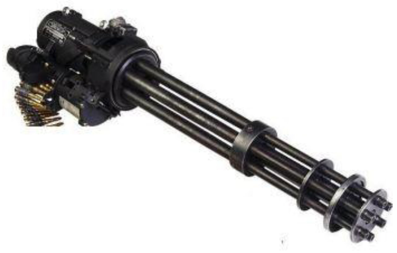
15]. The M134 machine gun is a 6-barrel aircraft gun developed by General Electric Company of the United States. It is mainly equipped on helicopters and can also be used as a vehicle weapon for mechanized infantry. It is to kill and assemble living targets and air defense. The M134 Gatling gun is composed of several barrels arranged in a ring, as
Figure 1.
In this paper, the critical speed model of high-speed rotating system is established, and the critical speed is determined through finite element modal analysis to determine the rigid/flexible state of barrel components in different speed regions; based on trajectory theory and unbalanced rotor theory, the barrel vibration model considering projectile weight and acceleration is established, and the muzzle is determined through the prestressed modal analysis of cantilever supported rotor under unbalanced force and moving mass Firing accuracy of vibrating counter rotating tube machine gun.
Each barrel rotates rapidly around the rotation center axis and reaches the stationary firing position in turn. Although the high-speed rotating barrel will increase the firing dispersion due to the centrifugal force, high firing speed and strong firepower can make up for the lack of accuracy, which makes M134 a very effective weapon to kill the living targets of the group.
The barrel and machine support of the Gatling, reference paper [
16] M134 imitation barrels and body frame. Since the barrel rotates at high speed, the solution of vibration characteristics of a Gatling gun is very complicated, as shown in
Figure 2.
When the front and rear diameters
D1 and
D2 of the Gatling weapon are not equal, the
is equal to,
when the front and rear diameters
D1 and
D2 of the Gatling weapon are equal, the angle
s equal 0.
Coriolis force
is showing as:
Substituting the angle, it is convenient to calculate:
If t is equal to 0, then the Coriolis force and the moment will be equal to 0.
According to the internal ballistic equation, the
p-value can be determined:
The pressure
and velocity
are obtained separately as shown in
Figure 3:
When the 7.62 × 51 mm NATO cartridge moves in the barrel, under the joint action of gunpowder gas and rifling, the projectile moves linearly along the barrel axis on the one hand and rotates on the other hand. At this time, there is a certain force on the bullet and barrel. From Equations (5)–(8), the rifling guide side will give the bullet a driving edge force N and give the barrel’s lateral force and axis force. As shown in
Figure 4 and
Figure 5, the OZ axis is parallel to the barrel axis, and the Z axis direction is the bullet movement direction. N is driving edge force N, fN is friction force. The lateral force on the barrel is
F1 and the axial force is
F2.
The circumferential torque is:
The lateral force of the barrel is:
The axis force of the barrel is:
when:
is the number of rifling elements, from
Table 1,
;
is the warhead radius;
is the driving force;
f is the friction coefficient, and the friction coefficient between metals, generally, it varies from 0.16 to 0.20,
f = 0.18.
The pressure of internal propellant gas belongs to the impact type of external force. The force on each rifling
and the force on each rifling
are shown in
Figure 8.
3. Theoretical Model
Depending on the hypothesis of the Bernoulli-Euler beam theory [
7,
17,
18,
19,
20,
21,
22], the tube vibration function with moving force and moving mass was solved [
10,
23,
24,
25]. Therefore, two theories are used, and the first is the ballistic theory, the second is the unbalanced rotor theory.
The vertical deformation of the barrel axis is represented by
y1, and the longitudinal deformation of the barrel axis is represented by
y2, as shown
Figure 5, The vibration equation of the barrel considering the weight and acceleration of the projectile is:
where:
is the elastic modulus of the material;
is the moment of inertia of the cross-section of a cage-like structure;
is the viscous damping coefficient;
is the vertical deformation of the axis;
is the longitudinal deformation;
is the resultant displacement.
is the material density;
is the cross-sectional area of the barrel;
and
are constants under the simplification of uniform section;
is the mass of the projectile;
is the axial force of barrel from muzzle to tail,
is the moving speed of the projectile;
is the acceleration of gravity;
is the travel of the bullet from interior ballistic calculation;
is the additional term of an external force acting on the barrel after considering the inertial effect of the bullet, and
is the Dirac function.
Similar to as
Figure 9, the calculation formula of
is as follows:
where:
is the moment of the barrel connector and 6 barrels,
is the mass of the bullet,
n is the number of the bullet. After calculation, its internal ballistic time is only 1.2 ms. The practical firing rate of M134 is 2000 rpm, that is,
n = 1;
The bullet goes through an unbalanced force, under the action of the unbalanced force, the rotor will produce vibration. At high speed, even a small mass eccentricity will produce a larger centrifugal force. The data are obtained from their modeling, and some are obtained from relevant literature [
13,
14,
15,
17].
The gun has an rpm from 300 to 6000, and the time interval is 200 ms to 10 ms. By the time the second bullet was started, the first bullet was already out of the gun. There is no interaction between the first and second bullet. In addition, two bullets do not appear in the barrels at the same time. The Gatling gun rotation rate is at
Table 2.
According to the size of each part, the solid is drawn by 3D software, and then imported into the finite element software, which is divided by hexahedral mesh, and the calculated model is obtained.
During the rotation of the barrel group continuously driven by the motor, the bullet moves along the barrel from back to front, which will cause the vibration caused by the additional mass. In addition, it is also a recognition that the bullet causes the additional vibration of the barrel assembly due to the unbalanced mass. Therefore, it is better that the lighter mass of the bullet and which will not affect the barrel assembly.
The above formula shows that once there is , the acceleration will change, which aggravates the change of and aggravates the speed fluctuation.
Simultaneously, there is a discovery that there is no distinction of the energy but the speed.
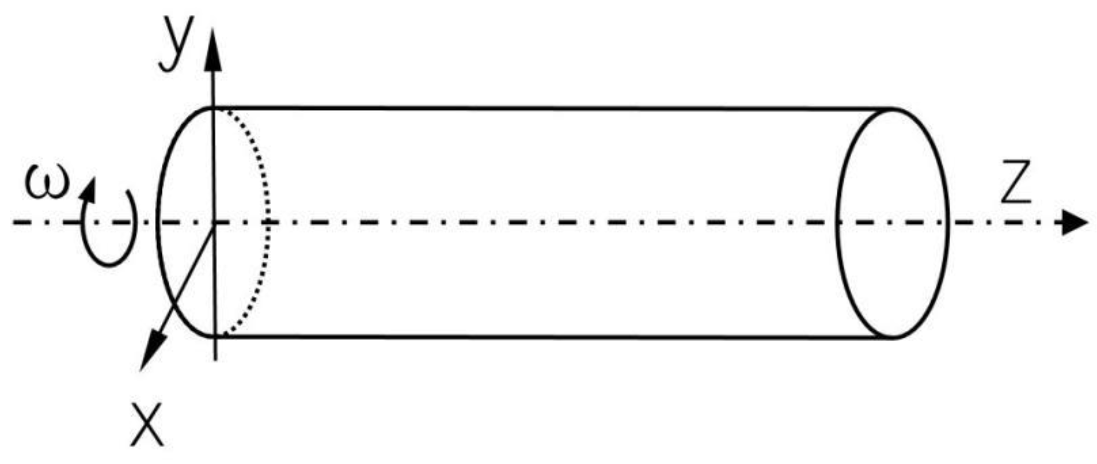
4. Distinction between Rigidity and Flexibility of Cantilever Rotor
The cantilever rotor was studied, and the axis coincides with the cantilever beam, the XY plane is connected with other structures, and the structure rotates around the Z axis, as
Figure 10. It calls a rotary squirrel cage cantilever [
3].
Hence, it is necessary to study the influence of the bullet launching process of Gatling weapon, especially the force and moment are caused when the bullet moves in the barrel. If the practical firing rate is 2000 rpm, then the rotation rate is 34.9 rad/s.
In the rotating system, the mass center of each micro section of the rotor can not be strictly on the rotating axis. Therefore, when the rotor rotates, there will be lateral interference, and it will cause strong vibration of the system at some speed. In this case, the speed is the critical speed [
26,
27].
The purpose of understanding the critical speed is to try to make the compressor’s working speed avoid the critical speed, to avoid resonance. Generally, the rated working speed n of the centrifugal compressor shaft is either lower than the first critical speed of the rotor, or between the first critical speed .
Let’s give it a modal analysis, add it some rotation velocity of 34.9 rad/s, it gives me some results, let us see that it is a component: a rigid or flexible component comes from at a certain speed.
This is the Campbell diagram for the M134 Gatling gun, as
Figure 11.
From
Figure 11, critical speed
= 8.0248 rad/s, from the
Table 2, Gatling gun rpm is 300–500, this M134 is rigid rotor; and for others, rpm is 1000–6000, the M134 is the flexible rotor. M134 usually works under a flexible barrel. With or without rotation rate, the M134 Gatling gun has the first 8 frequencies, as shown in
Table 3 below:
However, under the action of tension force, the structural stiffness will increase and the frequency will increase. On the contrary, under the action of compression force, the structural stiffness will decrease and the frequency will decrease. This prestress is a compression force.
5. Result Simulation
As we research the force of the rotary cantilever structure, it has to be researched in the ANSYS workbench. If the practical firing rate is 2000 rpm, then the rotation rate is 34.9 rad/s.
It is from the original parameters, such as elastic modulus E which is 2 × 10
11 Pa. maximum results are similar to
Figure 13,
Figure 14,
Figure 15 and
Figure 16. In the plane perpendicular to the barrel axis, this deformation data is very small, and the data is very large in the root of the barrel. Additionally, in the simulation, add the bullet’s x displacement as
Figure 15 and the force on the bullet’s as
Figure 16, which is as
Figure 8.
6. Optimization of the Cantilever Rotor System
6.1. Increase the Elastic Modulus of Barrel Material
The elastic modulus of the barrel material is at elastic modulus E which is 2 × 10
11 Pa. Let the elastic modulus by 10% of the upper and lower, the upper elastic modulus is 2.2 × 10
11 Pa and the lower elastic modulus is 1.8 × 10
11 Pa. In addition, the maximum of X and Y is shown in
Figure 17 and
Figure 18.
And the maximum of X and Y is shown in
Table 4.
The reductions are as follows:
Therefore, with the increasing of the elastic modulus, the barrel deformation of X and Y decreases, reaching nearly 20%. The larger the E value of steel, the smaller the muzzle deformation.
6.2. Simulation by Changing the Position of the Second Enclosure
The second enclosure of M134 is 225 mm to the body parts of the Gatling gun, and the L value is 225 mm. We change the L value of the second enclosure, its L value is 200 mm or 250 mm. The second enclosure is closer to the weapon body if L is equal to 200 mm. In addition, the second enclosure is farther away from the weapon body if L is equal to 250 mm. The L is shown in
Figure 19.
6.2.1. The Weapon Frequency from L
The frequency from the L changes is from the Ansys Workbench, the frequency is the list in
Table 5.
From
Table 5, the M134 can not fire at 1000 rpm, because this is close to the fundamental frequency.
Figure 21.
Frequency of L which value is 200 mm.
Figure 21.
Frequency of L which value is 200 mm.
Else if L value is 250 mm, which is as
Figure 22.
Figure 22.
Frequency of L which value is 250 mm.
Figure 22.
Frequency of L which value is 250 mm.
By comparing the three schemes, we can see how appropriate the M134 is designed and far away from the firing frequency.
6.2.2. The Barrel Deformation Closest to rpm
From
Figure 23,
Figure 24 and
Figure 25, we can see that the frequency close to the launch frequency, the L value is 225 mm, which can only be regarded as the medium level. After all, the muzzle has a 1.5 mm offset, which is only about 1 mm offset from the 250 mm muzzle. Compared with 200 mm, the muzzle has an offset of nearly 6 mm.
6.3. Simulation of Changing the Cross-Sectional Area
That is not possible, because the cross-sectional area must be accurate. It is about 10% at most. Since it is a military product, it must be strictly required. If it reduces the effect by 10%, as shown in
Figure 26.
And the maximum of X and Y is shown in
Table 6.
From
Table 6, with
Table 1, so the barrel is only 801.6 mm, and the original x result is 0.0060 mm, and 0.0108 mm in the Y direction, the new gun X direction is 0.0045 mm and Y direction is 0.0085 mm in. Now it is equivalent to the 600 m target, then the X offset of the original gun
x0 is 4.49 mm, the Y offset
y0 is 7.49 mm, and the X offset of the new gun X
j is 3.37 mm and the Y offset Y
j is 6.36 mm. Let’s calculate as follows Equation (21):
By reducing the cross-sectional area by 10%, a good result as Equation (21) can be achieved. The deformation of X and Y is smaller, but there are other components in it. If they can’t be put down, they still have to be the same size as before [
28].
7. Test and Data
We used the same number of barrels and the same configuration of the front structure of the barrel to shoot. Simulating shooting with 2000 rpm, and place the target 2000 m away. The shot image is shown in
Figure 27.
Record the target center and the center position of the two shooting methods, and shown in
Figure 28 below, the unit X and Y is meter. The absolute value decreases the range of R60 m.
8. Conclusions
After studying the M134 cantilever rotor, the following conclusions are obtained:
- (1)
If the M134 Gatling gun rpm is 300–500, this M134 rotor is rigid, and for others, rpm is 1000–6000, the M134 rotor is the flexible rotor. It’s still a good way to distinguish weapons according to the rpm. With the rpm of 3000, the barrels are neither twisted nor skewed, but stretched along the axis of the barrel, which is very beneficial to shooting, with the fourth frequency of 51.76 Hz. The best shooting is 300–500 for low-frequency shooting and 3000 for high-frequency shooting.
- (2)
The increase of the elastic modulus is helpful to reduce the displacement of the barrel. Improve shooting accuracy according to the reduced vibration. The barrel deformation can be increased from 1.8 × 10¹¹ to 2.2 × 10¹¹. The X and Y directions of the muzzle can be reduced by 18%. The absolute value decreases the range of R60 cm from 2000 m away.
- (3)
It is not by changing the cross-sectional area, although there are some good results, there are some other military products in it, the other reason is that the dimensions are fixed.
- (4)
With the 3000 rpm, the barrels are neither twisted nor skewed, but stretched along the axis of the barrel, which is very beneficial to shooting, with the fourth-frequency of 51.76 Hz, the Gatling gun shoots at 3105.6 rpm (51.76 × 60). 3000 rpm is correct and reasonable.


