
Active Deformation Patterns in the Northern Birjand Mountains of the Sistan Suture Zone, Iran


 and
and 
Abstract
:1. Introduction
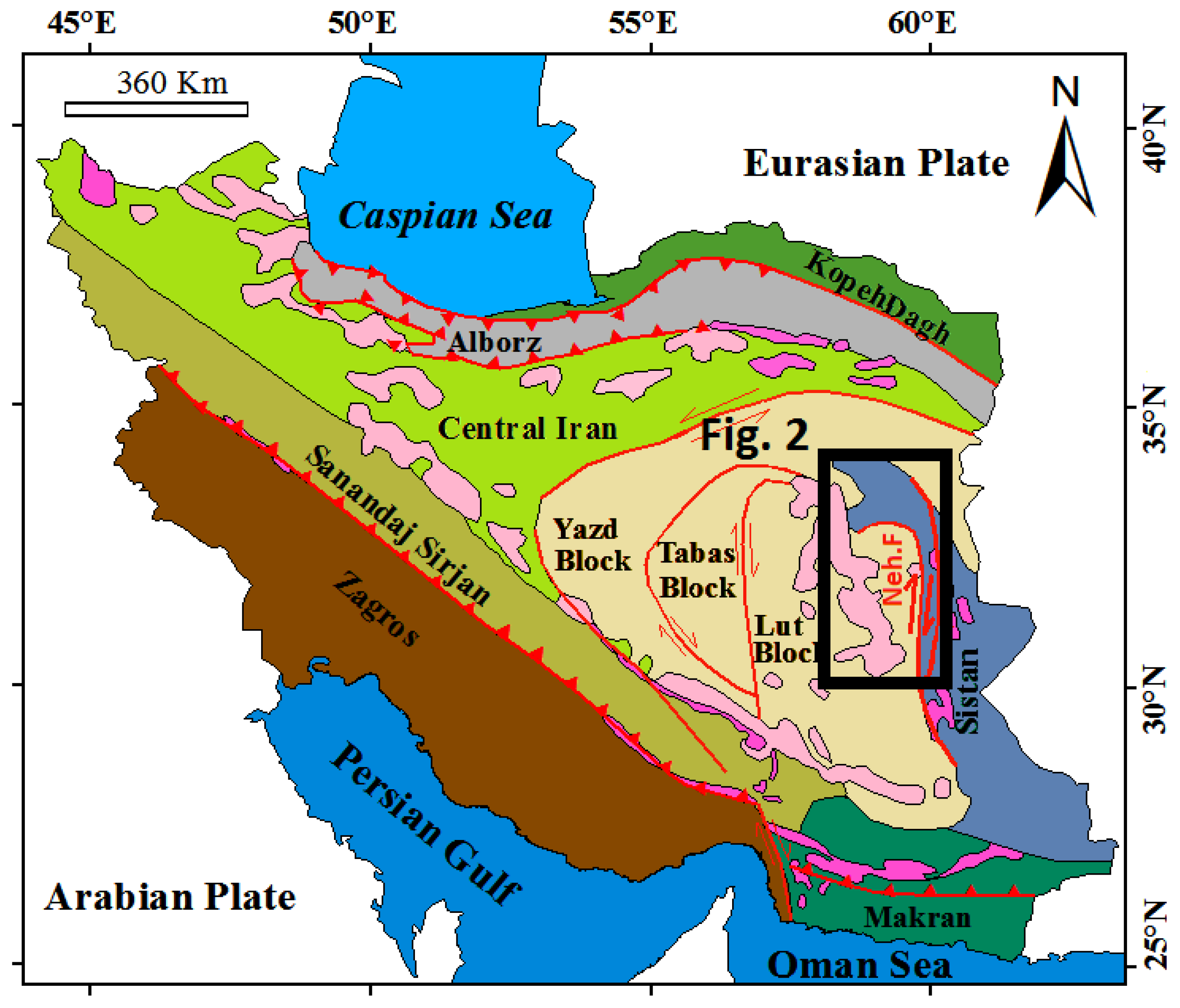
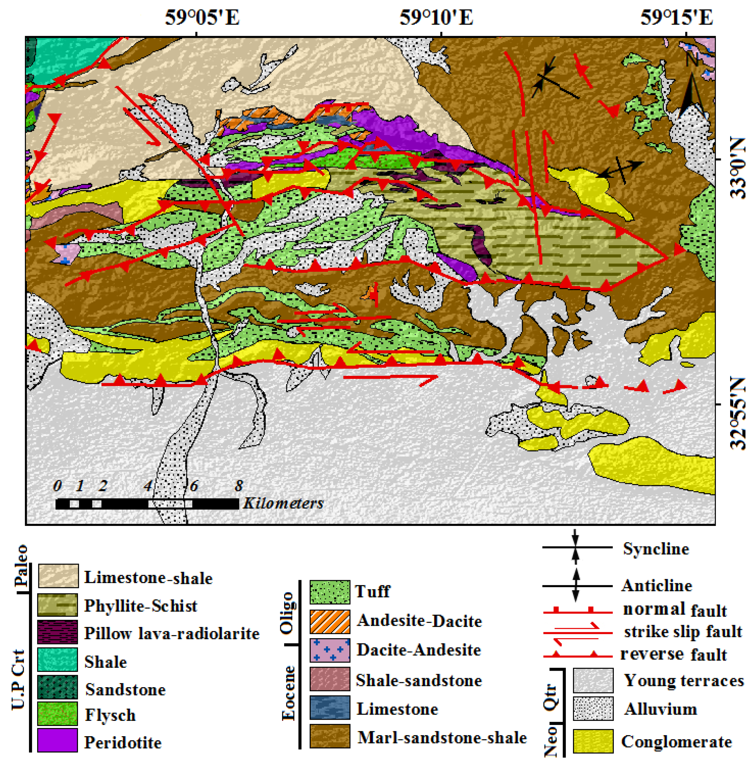
2. Tectonic and Geological Setting
3. Material and Methods
4. Results
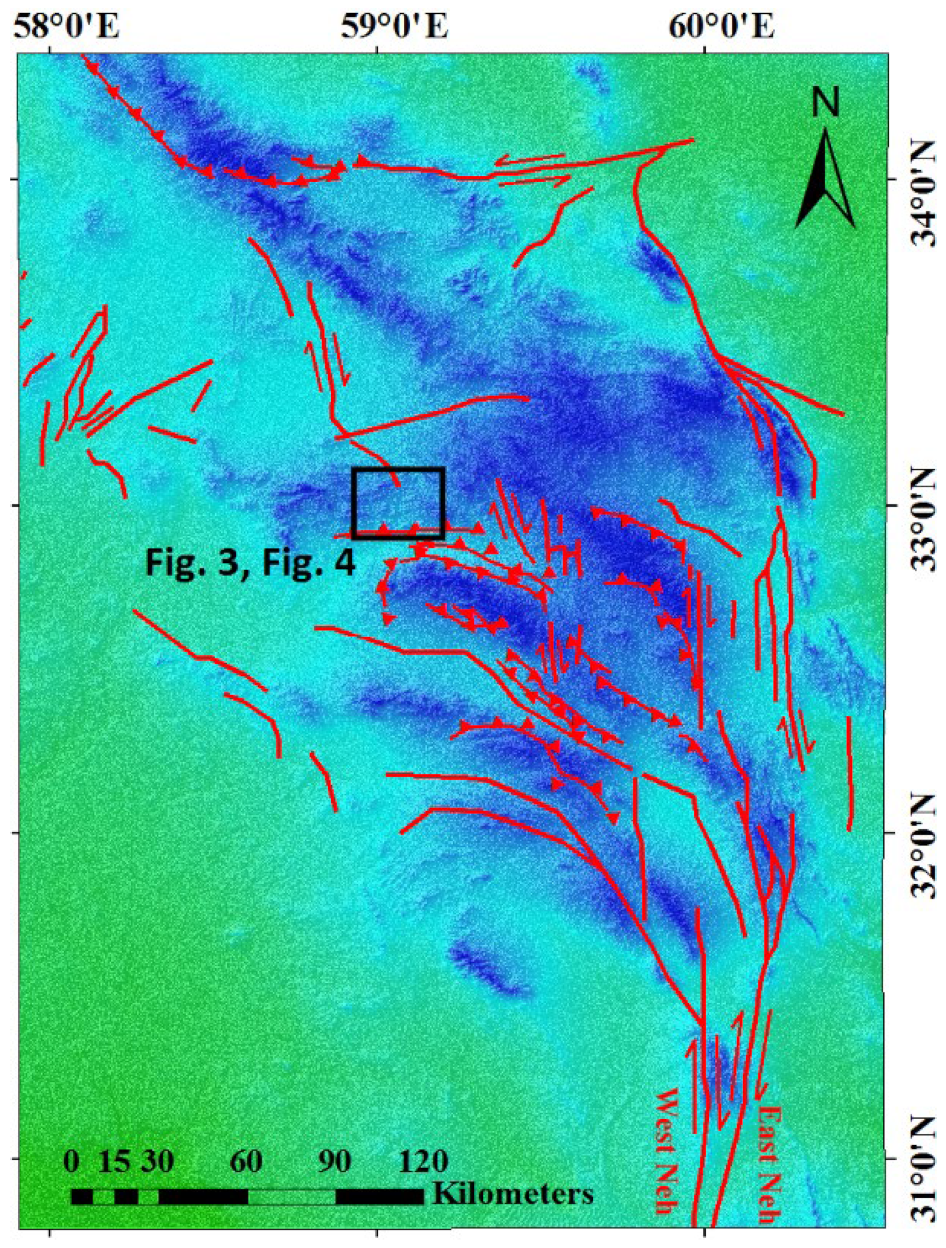
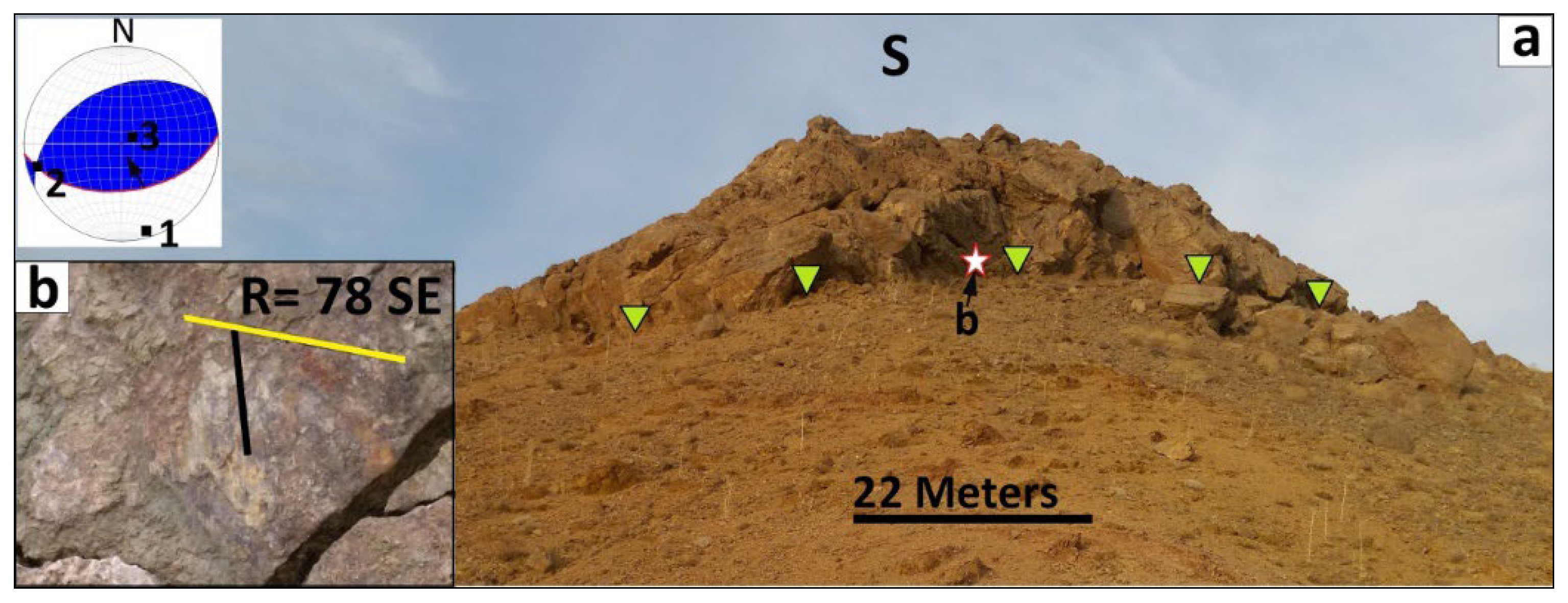
4.1. The Nehbandan Fault System
4.1.1. F1 Fault
4.1.2. F2 Fault
4.1.3. F3 Fault
4.1.4. F4 Fault
4.1.5. F5 Fault
4.1.6. F6 Fault
4.1.7. F7 Fault
5. Discussion
6. Conclusions
Author Contributions
Funding
Institutional Review Board Statement
Informed Consent Statement
Data Availability Statement
Acknowledgments
Conflicts of Interest
References
- Jackson, J. Partitioning of strike-slip and convergent motion between Eurasia and Arabia in eastern Turkey and the Caucasus. J. Geophys. Res. Solid Earth 1992, 97, 12471–12479. [Google Scholar] [CrossRef]
- Ghanbarian, M.A.; Yassaghi, A.; Derakhshani, R. Detecting a sinistral transpressional deformation belt in the Zagros. Geosciences 2021, 11, 226. [Google Scholar] [CrossRef]
- Berberian, M.; King, G. Towards a paleogeography and tectonic evolution of Iran. Can. J. Earth Sci. 1981, 18, 210–265. [Google Scholar] [CrossRef]
- Meyer, B.; Le Dortz, K. Strike-slip kinematics in central and eastern Iran: Estimating fault slip-rates averaged over the Holocene. Tectonics 2007, 26, 1–20. [Google Scholar] [CrossRef]
- Tirrul, R.; Bell, I.; Griffis, R.; Camp, V. The Sistan suture zone of eastern Iran. Geol. Soc. Am. Bull. 1983, 94, 134–150. [Google Scholar] [CrossRef]
- Jackson, J.; McKenzie, D. Active tectonics of the Alpine—Himalayan Belt between western Turkey and Pakistan. Geophys. J. Int. 1984, 77, 185–264. [Google Scholar] [CrossRef]
- Walker, R.; Khatib, M. Active faulting in the Birjand region of NE Iran. Tectonics 2006, 25, 1–17. [Google Scholar] [CrossRef]
- Şengör, A.; Altıner, D.; Cin, A.; Ustaömer, T.; Hsü, K. Origin and assembly of the Tethyside orogenic collage at the expense of Gondwana Land. Geol. Soc. Lond. Spec. Publ. 1988, 37, 119–181. [Google Scholar] [CrossRef]
- Samimi, S.; Gholami, E.; Khatib, M.; Madanipour, S.; Lisker, F. Transpression and exhumation of granitoid plutons along the northern part of the Nehbandan fault system in the sistan suture zone, Eastern Iran. Geotectonics 2020, 54, 130–144. [Google Scholar] [CrossRef]
- Comijany, N.A.; Khatib, M.M.; Gholami, E.; Shabestari, G.M.; Zarrinkoub, M.H. Estimation of shortening and vergence in northern part of Sistan Suture Zone for determination of kinematic convergent vectors. J. Adv. Appl. Geol. 2019, 9, 232–255. [Google Scholar] [CrossRef]
- Mousavi, Z.; Walpersdorf, A.; Walker, R.; Tavakoli, F.; Pathier, E.; Nankali, H.; Nilfouroushan, F.; Djamour, Y. Global Positioning System constraints on the active tectonics of NE Iran and the South Caspian region. Earth Planet. Sci. Lett. 2013, 377, 287–298. [Google Scholar] [CrossRef]
- Baniadam, F.; Shabanian, E.; Bellier, O. The kinematics of the Dasht-e Bayaz earthquake fault during Pliocene-Quaternary: Implications for the tectonics of eastern Central Iran. Tectonophysics 2019, 772, 228218. [Google Scholar] [CrossRef]
- Taghipour, K.; Khatib, M.M.; Heyhat, M.; Shabanian, E.; Vaezihir, A. Evidence for distributed active strike-slip faulting in NW Iran: The Maragheh and Salmas fault zones. Tectonophysics 2018, 742, 15–33. [Google Scholar] [CrossRef]
- Ezati, M.; Gholami, E. Neotectonics of the Central Kopeh Dagh drainage basins, NE Iran. Arab. J. Geosci. 2022, 15, 992. [Google Scholar] [CrossRef]
- Ezati, M.; Agh-Atabai, M. Estimating rate of tectonic activity in central Kopeh dagh using morphometric indices. J. Tethys 2014, 2, 314–326. [Google Scholar]
- Bhattacharyya, K.; Dwivedi, H.V.; Das, J.P.; Damania, S. Structural geometry, microstructural and strain analyses of L-tectonites from Paleoproterozoic orthogneiss: Insights into local transport-parallel constrictional strain in the Sikkim Himalayan fold thrust belt. J. Asian Earth Sci. 2015, 107, 212–231. [Google Scholar] [CrossRef]
- Vera, E.R.; Mescua, J.; Folguera, A.; Becker, T.; Sagripanti, L.; Fennell, L.; Orts, D.; Ramos, V.A. Evolution of the Chos Malal and Agrio fold and thrust belts, Andes of Neuquén: Insights from structural analysis and apatite fission track dating. J. S. Am. Earth Sci. 2015, 64, 418–433. [Google Scholar] [CrossRef]
- Ghanbarian, M.A.; Derakhshani, R. The folds and faults kinematic association in Zagros. Sci. Rep. 2022, 12, 8350. [Google Scholar] [CrossRef]
- Yassaghi, A.; Madanipour, S. Influence of a transverse basement fault on along-strike variations in the geometry of an inverted normal fault: Case study of the Mosha Fault, Central Alborz Range, Iran. J. Struct. Geol. 2008, 30, 1507–1519. [Google Scholar] [CrossRef]
- Bose, S.; Das, A.; Samantaray, S.; Banerjee, S.; Gupta, S. Late tectonic reorientation of lineaments and fabrics in the northern Eastern Ghats Province, India: Evaluating the role of the Mahanadi Shear Zone. J. Asian Earth Sci. 2020, 201, 104071. [Google Scholar] [CrossRef]
- Shi, G.; Shen, C.; Zattin, M.; Wang, H.; Yang, C.; Liang, C. Late Cretaceous-Cenozoic exhumation of the Helanshan Mt. Range, western Ordos fold-thrust belt, China: Insights from structural and apatite fission track analyses. J. Asian Earth Sci. 2019, 176, 196–208. [Google Scholar] [CrossRef]
- Zebari, M.; Balling, P.; Grützner, C.; Navabpour, P.; Witte, J.; Ustaszewski, K. Structural style of the NW Zagros Mountains and the role of basement thrusting for its Mountain Front Flexure, Kurdistan Region of Iraq. J. Struct. Geol. 2020, 141, 104206. [Google Scholar] [CrossRef]
- Ezati, M.; Gholami, E.; Mousavi, S.M. Paleostress regime reconstruction based on brittle structure analysis in the Shekarab Mountain, Eastern Iran. Arab. J. Geosci. 2020, 13, 1232. [Google Scholar] [CrossRef]
- Ezati, M.; Gholami, E.; Mousavi, S.M. Tectonic activity level evaluation using geomorphic indices in the Shekarab Mountains, Eastern Iran. Arab. J. Geosci. 2021, 14, 385. [Google Scholar] [CrossRef]
- Camp, V.; Griffis, R. Character, genesis and tectonic setting of igneous rocks in the Sistan suture zone, eastern Iran. Lithos 1982, 15, 221–239. [Google Scholar] [CrossRef]
- Rashidi, A.; Abbassi, M.-R.; Nilfouroushan, F.; Shafiei, S.; Derakhshani, R.; Nemati, M. Morphotectonic and earthquake data analysis of interactional faults in Sabzevaran Area, SE Iran. J. Struct. Geol. 2020, 139, 104147. [Google Scholar] [CrossRef]
- Rashidi, A.; Kianimehr, H.; Shafieibafti, S.; Mehrabi, A.; Derakhshani, R. Active faults in the west of the Lut block (Central Iran). Geophys. Res. 2021, 22, 70–84. [Google Scholar] [CrossRef]
- Freund, R. Rotation of strike slip faults in Sistan, southeast Iran. J. Geol. 1970, 78, 188–200. [Google Scholar] [CrossRef]
- Rashidi, A.; Khatib, M.M.; Derakhshani, R. Structural Characteristics and Formation Mechanism of the Earth Fissures as a Geohazard in Birjand, Iran. Appl. Sci. 2022, 12, 4144. [Google Scholar] [CrossRef]
- Khatib, M. Structural Analysis of Southern Birjand Mountains. Ph.D. Thesis, Shahid Beheshti University, Tehran, Iran, 1998. [Google Scholar]
- Rashidi, A.; Khatib, M.M.; Nilfouroushan, F.; Derakhshani, R.; Mousavi, S.M.; Kianimehr, H.; Djamour, Y. Strain rate and stress fields in the West and South Lut block, Iran: Insights from the inversion of focal mechanism and geodetic data. Tectonophysics 2019, 766, 94–114. [Google Scholar] [CrossRef]
- Rashidi, A.; Derakhshani, R. Strain and Moment-Rates from GPS and Seismological Data in Northern Iran: Implications for an Evaluation of Stress Trajectories and Probabilistic Fault Rupture Hazard. Remote Sens. 2022, 14, 2219. [Google Scholar] [CrossRef]
- Allmendinger, R.W. FaultKin 8 Program. Available online: https://www.rickallmendinger.net/ (accessed on 12 February 2022).
- Berberian, M.; Yeats, R.S. Patterns of historical earthquake rupture in the Iranian Plateau. Bull. Seismol. Soc. Am. 1999, 89, 120–139. [Google Scholar]


| Fault Name | Geometric Position | Slicken Line Position | Fault Mechanism |
|---|---|---|---|
| F1 | N90E, 50S | S88E, 70 | Reverse with a dextral component |
| F2 | N84E, 50S | S28E, 48 | Reverse with a dextral component |
| F3 | N90E, 60N | N21E, 58 | Reverse with a sinistral component |
| F4 | N85E, 40N | N2E, 39 | Reverse with a sinistral component |
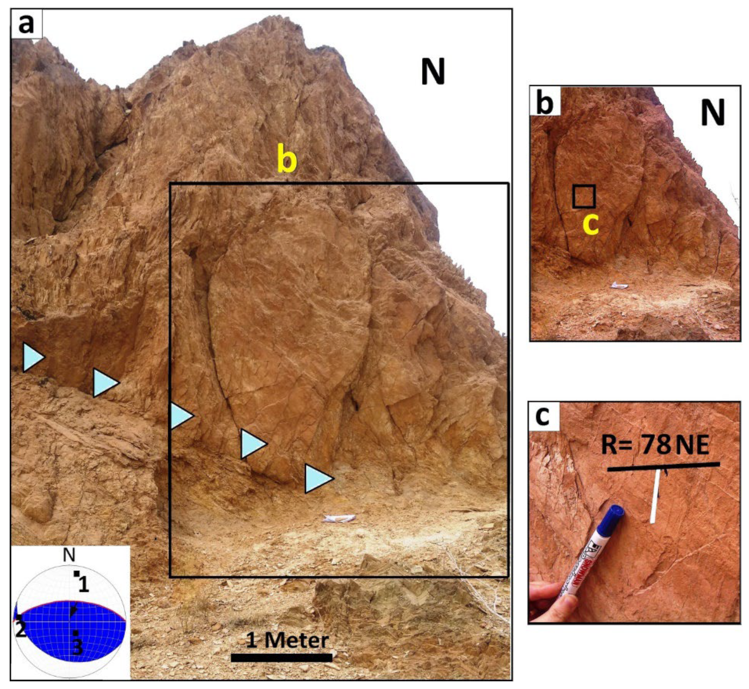
| F5 | N10W, 50NE | N4W, 8 | Sinistral with a normal component |
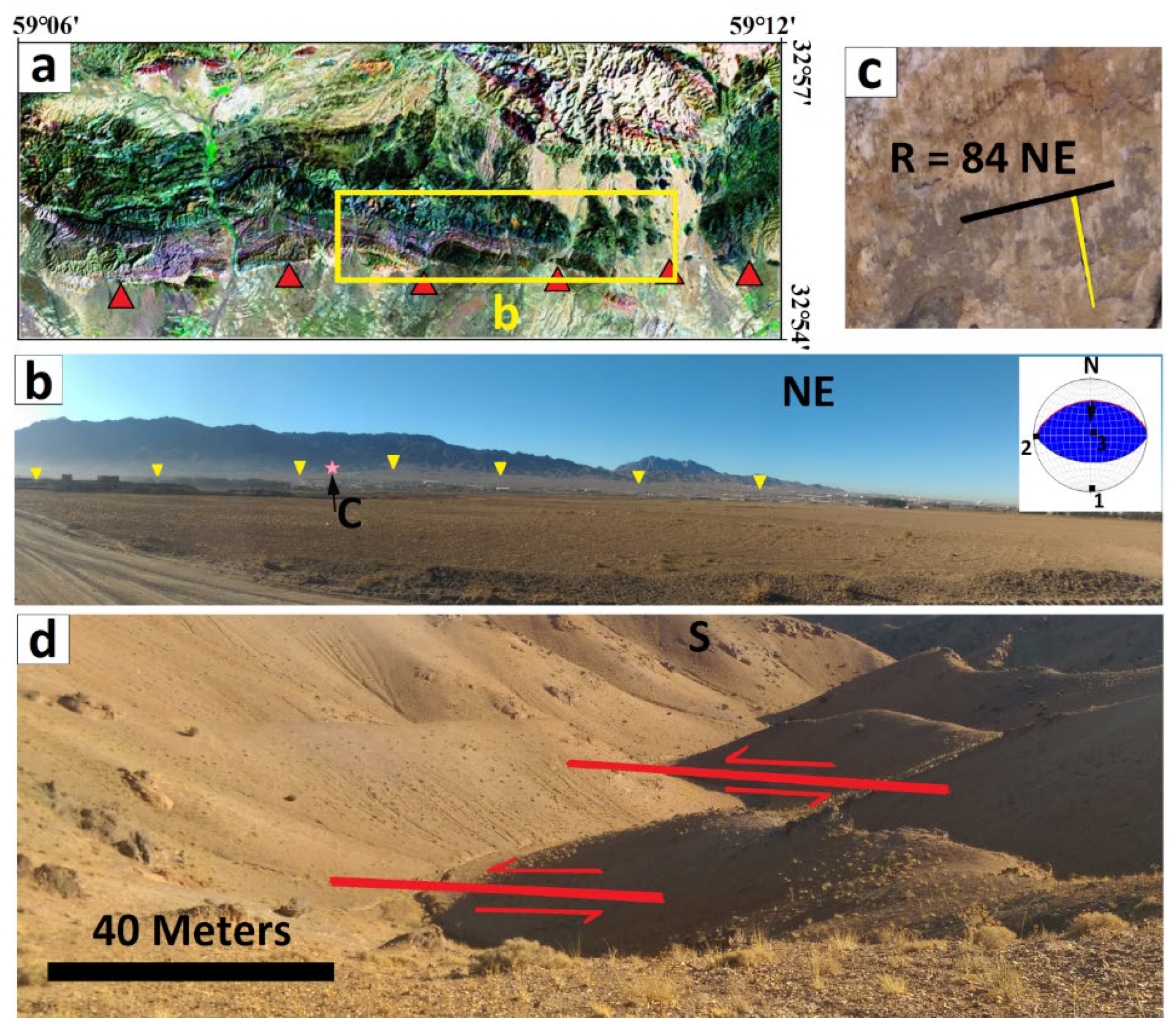
| F6 | N60W, 78SW | N76W, 19 | Sinistral with a reverse component |
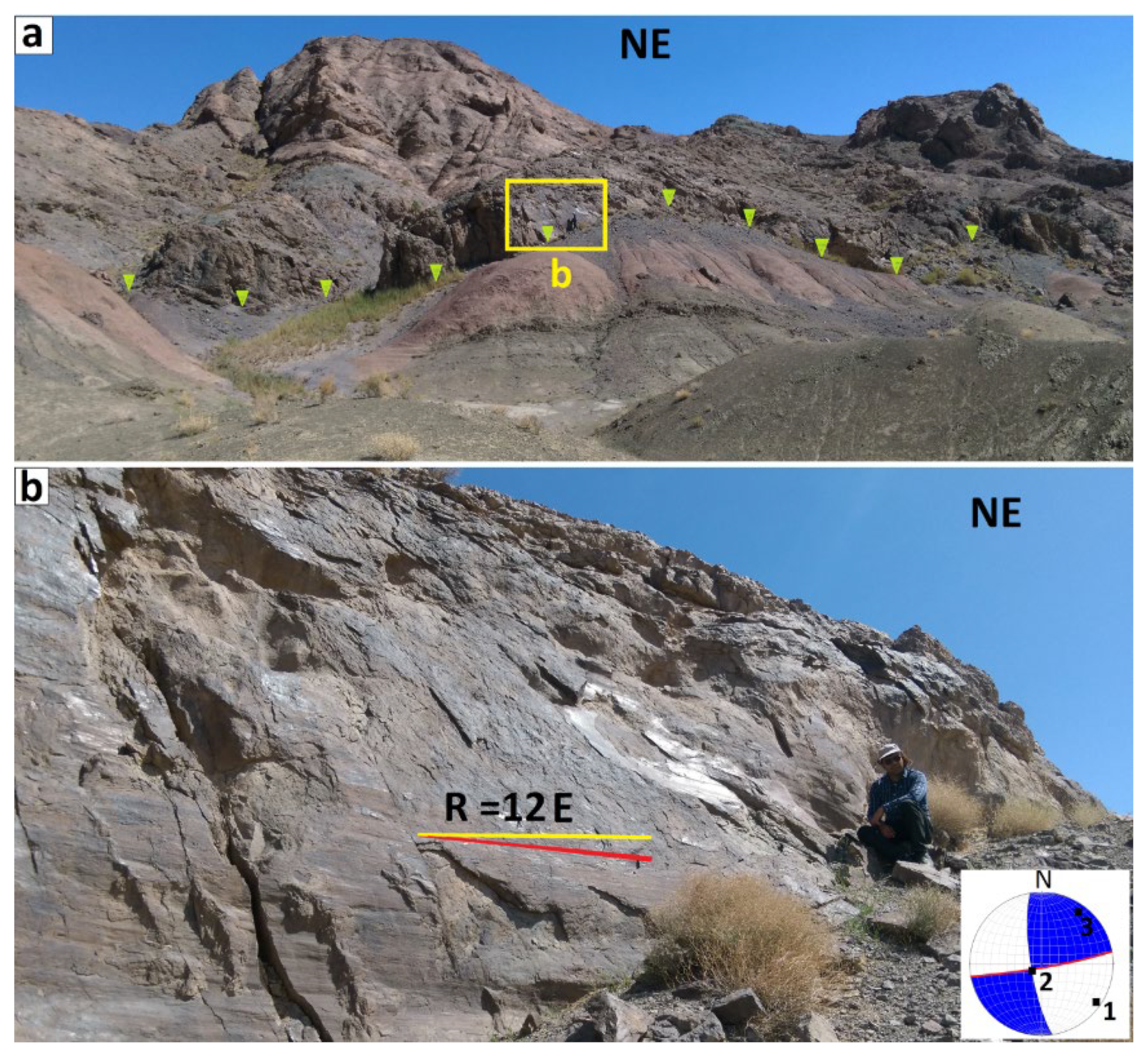
| F7 | N80E, 86SE | N80E, 11 | Dextral with a reverse component |
Publisher’s Note: MDPI stays neutral with regard to jurisdictional claims in published maps and institutional affiliations. |
© 2022 by the authors. Licensee MDPI, Basel, Switzerland. This article is an open access article distributed under the terms and conditions of the Creative Commons Attribution (CC BY) license (https://creativecommons.org/licenses/by/4.0/).
Share and Cite
Ezati, M.; Gholami, E.; Mousavi, S.M.; Rashidi, A.; Derakhshani, R. Active Deformation Patterns in the Northern Birjand Mountains of the Sistan Suture Zone, Iran. Appl. Sci. 2022, 12, 6625. https://doi.org/10.3390/app12136625
Ezati M, Gholami E, Mousavi SM, Rashidi A, Derakhshani R. Active Deformation Patterns in the Northern Birjand Mountains of the Sistan Suture Zone, Iran. Applied Sciences. 2022; 12(13):6625. https://doi.org/10.3390/app12136625
Chicago/Turabian StyleEzati, Maryam, Ebrahim Gholami, Seyed Morteza Mousavi, Ahmad Rashidi, and Reza Derakhshani. 2022. "Active Deformation Patterns in the Northern Birjand Mountains of the Sistan Suture Zone, Iran" Applied Sciences 12, no. 13: 6625. https://doi.org/10.3390/app12136625
APA StyleEzati, M., Gholami, E., Mousavi, S. M., Rashidi, A., & Derakhshani, R. (2022). Active Deformation Patterns in the Northern Birjand Mountains of the Sistan Suture Zone, Iran. Applied Sciences, 12(13), 6625. https://doi.org/10.3390/app12136625