Article

Active Deformation Patterns in the Northern Birjand Mountains of the Sistan Suture Zone, Iran

1
Department of Geology, University of Birjand, Birjand 97174-34765, Iran
2
Department of Seismotectonics, International Institute of Earthquake Engineering and Seismology, Tehran 19537-14453, Iran
3
Department of Geology, Shahid Bahonar University of Kerman, Kerman 76169-13439, Iran
4
Department of Earth Sciences, Utrecht University, 3584 CB Utrecht, The Netherlands
*
Author to whom correspondence should be addressed.
Appl. Sci. 2022, 12(13), 6625; https://doi.org/10.3390/app12136625
Submission received: 7 June 2022 / Revised: 23 June 2022 / Accepted: 27 June 2022 / Published: 30 June 2022
(This article belongs to the Special Issue Geotechnical Engineering Hazards)

Abstract

:
In this paper, faults, one of the most important causes of geohazards, were investigated from a kinematic and geometric viewpoint in the northern part of the Sistan suture zone (SSZ), which serves as the boundary between the Afghan and Lut blocks. Furthermore, field evidence was analyzed in order to assess the structural type and deformation mechanism of the research area. In the northern Birjand mountain range, several ~E–W striking faults cut through geological units; geometric and kinematic analyses of these faults indicate that almost all faults have main reverse components, which reveals the existing compressional stress in the study area. The northern Birjand mountain range is characterized by four main reverse faults with ~E–W striking: F1–F4. The F1 and F2 reverse faults have southward dips, while the F3 and F4 reverse faults have northward dips. Moreover, the lengths of the F1, F2, F3, and F4 faults are 31, 17, 8, and 38 km, respectively. These faults, with reverse components that have interactive relationships with each other, form high relief structures. The study area’s main reverse faults, including F1 to F4, are extensions of the Nehbandan fault system, while their kinematics and geometry in the northern Birjand mountain range point to an N–S pop-up structure.

1. Introduction

Iran is situated in a tectonic convergence zone between the Eurasian and Arabian plates in the north and south, respectively. This convergence is mostly accommodated by the Alborz Mountains, the Zagros Mountains, and the Makran zone [1,2]. Iran, on the other hand, has a complex tectonic evolution associated with the Tethys history [3]. The closure of several Neo-Tethys oceanic domains in the late Cretaceous and early Tertiary can be seen by the formation of the SSZ, Nain Baft, and Sabzevar sutures [4]. The SSZ is located adjacent to the eastern Iranian border with Afghanistan and Pakistan [5]. The northward movement of Iran in relation to Afghanistan induces several right-lateral strike-slip faults on the edge of Lut [6,7]. The SSZ, which is overprinted by the Nehbandan fault at the eastern limit of the Lut block, is an accretionary prism of the Sistan Ocean between the Afghan and Lut blocks [8,9,10]. The western edge of the Lut block includes a number of N–S faults, including the Nayband, Sabzevaran, and Gowk faults, which are affected by the Arabia–Eurasia continental plate collision [11]. A number of significant seismic events in the SSZ occurred by strike-slip faults and their splays, which also play an important role in the current morphology of the area [12]. Iran’s predominant tectonic mode has shifted to strike-slip from compressional since the Pliocene [13]. As shown in Figure 1, the study area, including the Nehbandan faults branches, is located in the N–S Sistan suture zone. Detailed field surveys have not yet documented the northern Birjand mountain range in the Sistan suture zone in terms of its geometric kinematics. Moreover, in this research, the structural style of the study area was investigated using geometric–kinematic analysis. This methodology has been found to be useful in places such as northeast Iran [14,15]; the Himalayan fold-thrust belt [16]; the Andes [17]; the Zagros mountain range [18], the Mosha fault in the Central Alborz range, Iran [19]; NE Ghats Province, India [20], the western Ordos fold-thrust belt, China [21]; the NW Zagros Mountains, Kurdistan Region, Iraq [22]; and Shekarab Mountain in eastern Iran [23,24].

2. Tectonic and Geological Setting

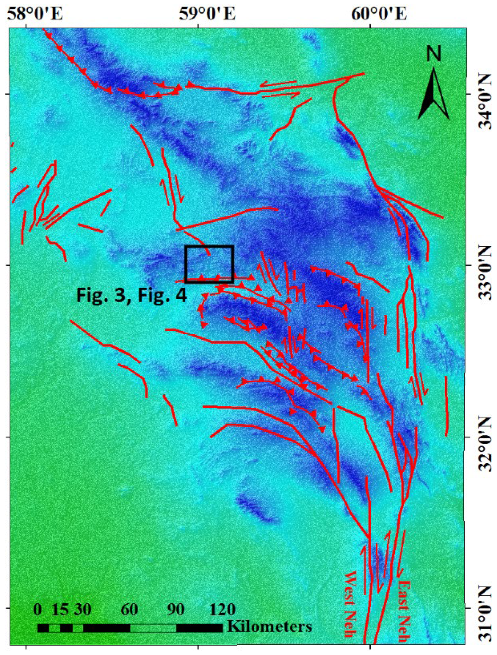
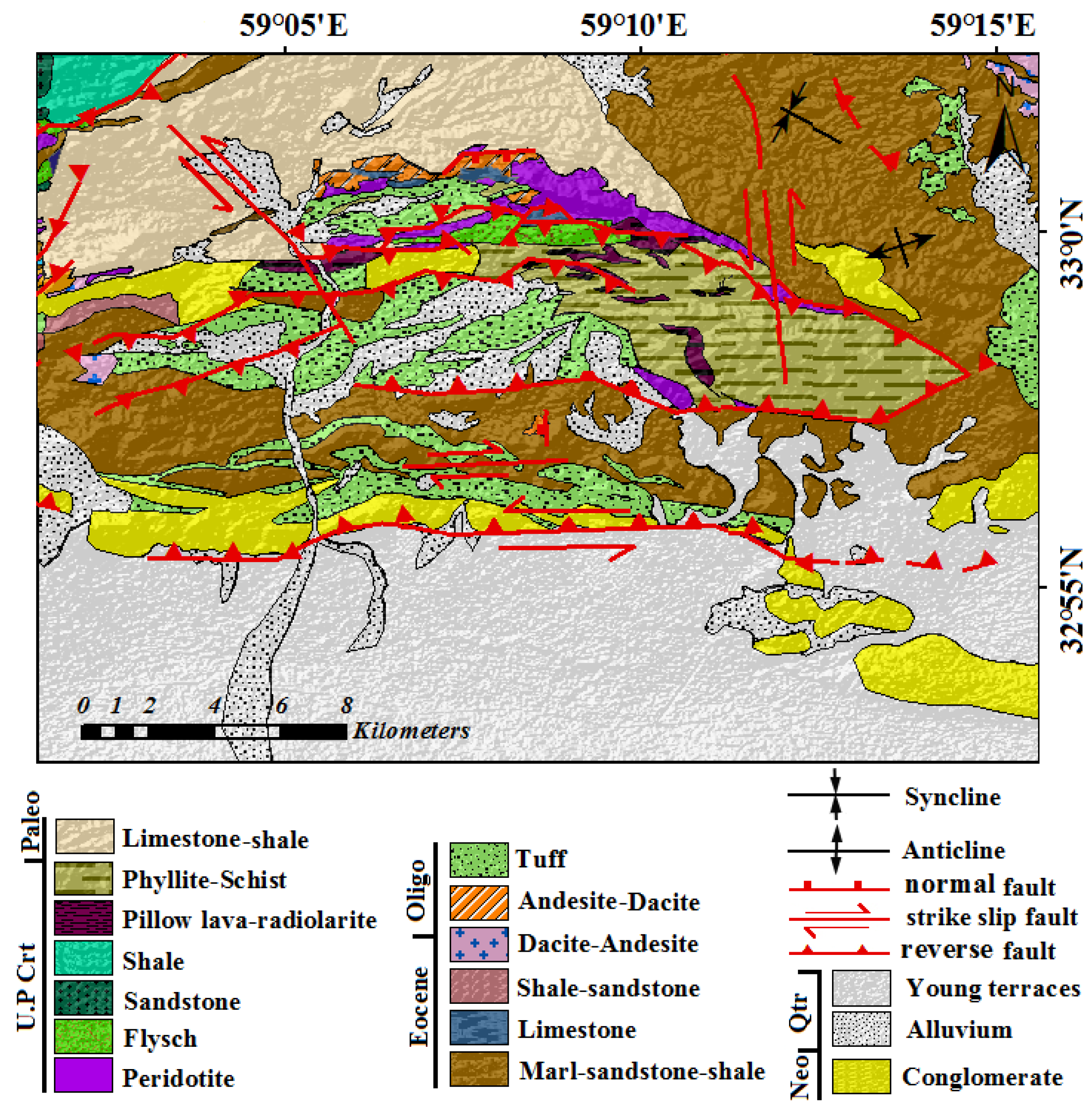
The Sistan suture zone, which has been defined by a deformed accretionary prism since the early Cretaceous, has a rather complex history that includes rifting, subductions, ophiolite emplacement, continental collision, and uplift, as well as at least three phases of Cenozoic deformation, which has resulted in its current state [8,25]. Several strike-slip faults bordering the Lut block accommodate the N–S right-lateral component of the shear between the Afghan and Lut blocks [4,26,27], resulting in a right-lateral shear with the N–NNE movement of Iran with respect to the stable Afghan block. Major N–S right-lateral strike-slip faulting dominates this zone, along with some E–W left-lateral strike-slip faults and some NW–SE reverse faults [28]. The region of Birjand is relatively elevated, with a series of roughly east–west linear mountain ranges that expose Late Cretaceous to Eocene ophiolite rocks of the SSZ, which are predominantly affected by shear zones [7,29]. The N–S trending Nehbandan strike-slip fault has sub-branches in its southern and northern terminals that are mainly reverse faults with an E–W trend [30]. Nearly all of the faults in the northern Birjand mountain range are reverse faults with a strike-slip component, according to geometric and kinematic analyses of identified faults (Table 1, Figure 2 and Figure 3). The main lithologies of the study area are ophiolite, phyllite, flysch, tuff, limestone, and young terraces (Figure 4).

3. Material and Methods

The spatial orientation of fault planes and associated slicken lines were measured as the fault kinematic data (Figure 3, Table 1). In addition, the digital elevation model (DEM), fieldwork, satellite images, and geological maps were used to study the structural style as well as the lithological information in the northern Birjand mountain range. To analyze the fault mechanisms, the kinematics and geometry of the faults were investigated using slicken lines. In order to conduct kinematic and structural analyses of the study area, the tilting and offset of the rock units and the orientation of the main fault planes were measured. The directions of principal stress, including sigma 1, sigma 2, and sigma 3, were determined using the kinematic axes method including P (shortening) and T (extension). The P and T axes correspond to the directions of the principal stress of sigma 1 and sigma 3, respectively [31,32]; we used this most robust method using FaultKin 8 software [33]. In order to reconstruct the tectonic history that led to the deformation of the northern Birjand mountain range, we analyzed the data collected from various sites and suggest a tectonic model to understand the structural style of the study area.

4. Results

To define the mechanisms of faults, it is necessary to comprehend their surface traces and kinematic/geometric properties. This section describes the fault patterns in order to comprehend the deformational patterns associated with the faults in the study area. This study collected brittle structures, including the spatial orientation of the fault planes and the associated slicken lines, from seven major faults. On the structural map, the faults and data collection sites are indicated. In order to determine the structural style and kinematic of the northern Birjand mountain range, we first attempted to analyze the brittle tectonic data collected from various sites. The Nehbandan fault system consists of the West Neh and East Neh, which run parallel to one another. The thrust splays of the Nehbandan fault system formed the northern Birjand mountain range (Figure 2). The main reverse faults of the northern Birjand mountain range, F1 to F4, are the continuation of the Nehbandan fault system. We characterized the kinematic–geometric relationships, displacement direction, the stress that exists in the intersection zones, and the angle between the intersecting lines in the northern Birjand mountain range. Therefore, using these parameters, we present the relationships between the structural zones and faults in the study area. In a two-dimensional view, some faults have no interaction with other faults (e.g., the F4 fault). Some exposed faults in the northern Birjand mountain range are characterized by their segmentations. For example, the east–west faults, such as F1 and F3, are composed of linked segments. The main reverse faults of the northern Birjand mountain range have nearly east–west strikes. The structural evidence for active faulting is described in the following sections.

4.1. The Nehbandan Fault System

Nehbandan fault, which delimits the boundary between the SSZ in the east and the Lut Block in the west (Figure 1), is approximately 400 km long and consists of multiple faults [34], including East Neh and West Neh on the western side of the SSZ (Figure 2) and the F1, F2, F3, and F4 reverse faults in the northern Birjand mountain range. Some reverse splays of the Nehbandan fault system have been located in the northern Birjand mountain range; F1, F2, F3, and F4 are the main reverse faults in the study area, which are reverse splays of the Nehbandan fault.

4.1.1. F1 Fault

The F1 fault, the northern reverse fault with ~E–W strike, is approximately 31 km long. This fault has uplifted upper Cretaceous rocks (Figure 5), which are the oldest exposed rocks in the study region. The fault plane with an attitude of N90° E, 50° S and a slicken line with 71 SE rakes is a reverse fault with a minor dextral component.

4.1.2. F2 Fault

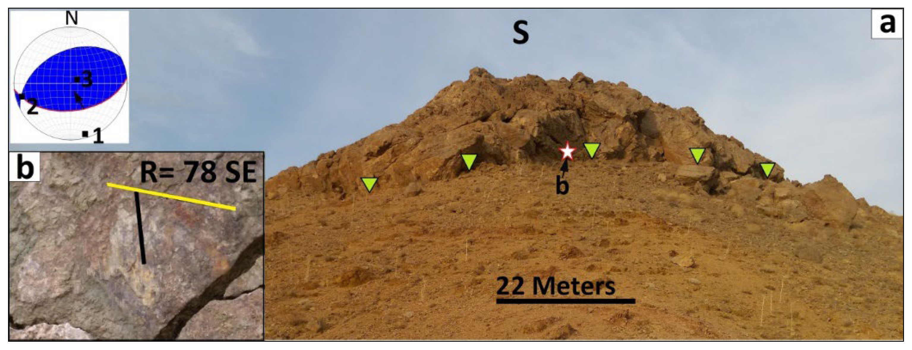
The F2 fault, a reverse fault with a minor dextral component, is approximately 13 km in length and trends E–W. This fault is responsible for the movement of upper Cretaceous, Eocene, and Oligocene rocks (Figure 6). Fault F2 thrusted the Eocene–Oligocene units over the upper Cretaceous units. The geometric position of this fault is N84° E, 50° S, and its slicken line shows a 78° SE rake.

4.1.3. F3 Fault

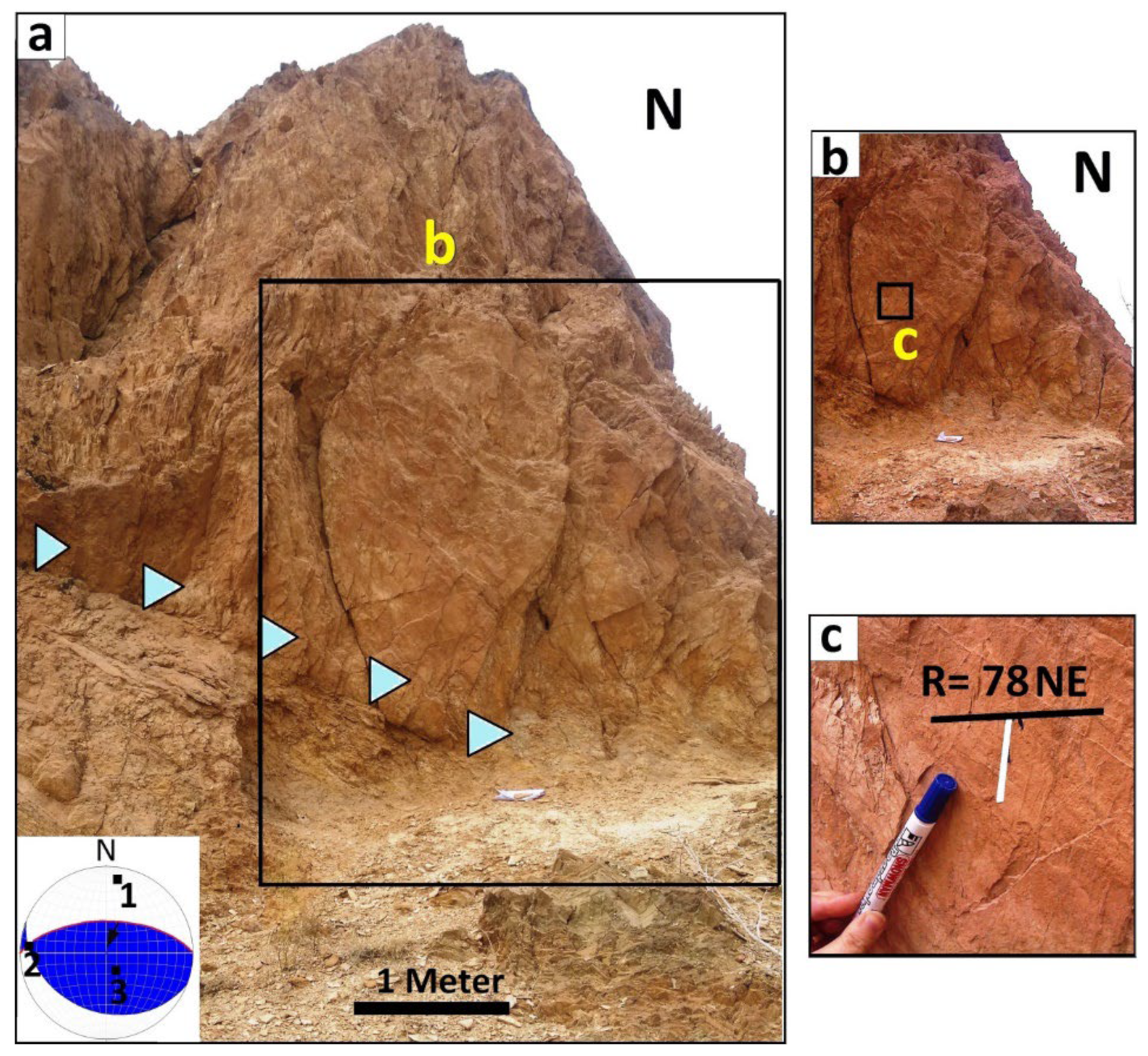
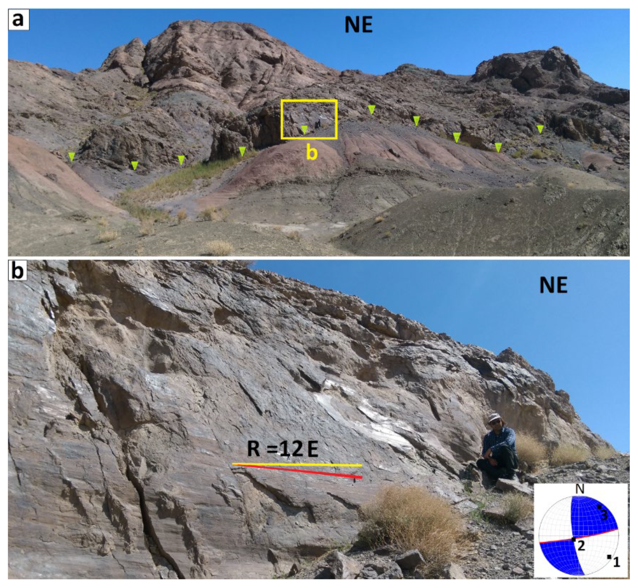
The approximately 8 km-long F3 fault, with an attitude of N90° E, 50° S and a slicken line with a rake of 78° NE, is a reverse fault with a minor left-lateral component (Figure 7), while the phyllite–schist units are elevated as a result of its activity. Along this fault, upper Cretaceous rock units were thrust over the Eocene rock units; thus, the juxtaposition of older and younger rock units indicates that this fault moved in reverse.

4.1.4. F4 Fault

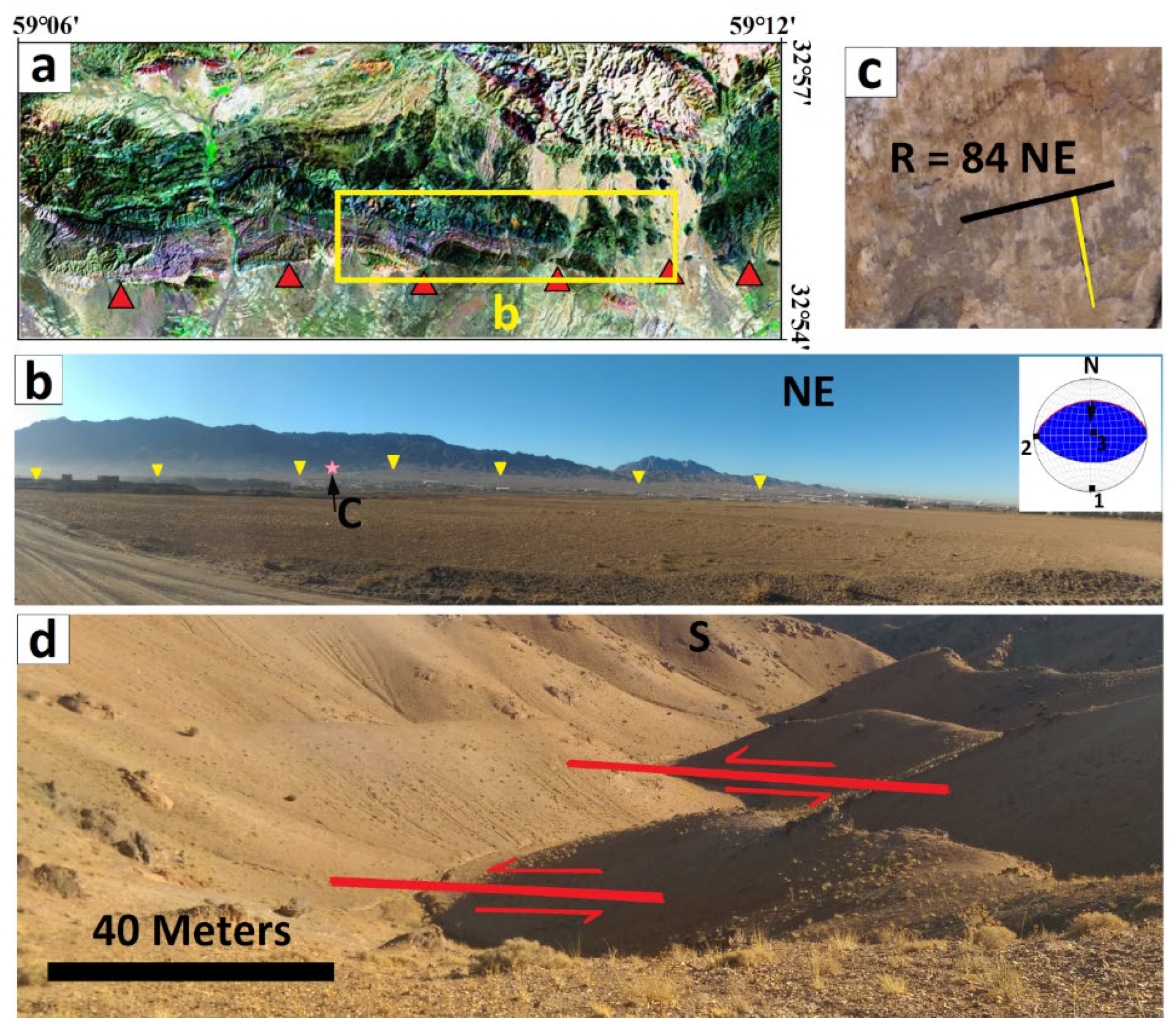
The satellite image and digital elevation model (DEM) reveal a system of folds along the F4 fault in the southern margin of the northern Birjand mountain range. Figure 8b depicts the western portion of the F4 fault, the southernmost fault in the study area. The F4 fault is about 38 km in length and is a reverse fault with a sinistral component fault that trends ~E–W; this fault is responsible for the uplift of the Neogean sediments (Figure 8). Moreover, the F4 fault has cut and moved the Pliocene–Quaternary sediments. Along this active fault, rivers and Quaternary offsets deflect nearly 40 m (Figure 8d). The river offsets and the overlying of older units on younger units indicate reverse and sinistral movements along this fault.

4.1.5. F5 Fault

The F5 fault has a length of approximately 11 km, is sinistral with a normal component fault, and trends ~NW–SE; this fault has displaced the F1 fault (Figure 3). The cumulative offset along this fault in the upper Cretaceous and Eocene units is approximately 0.5 km.

4.1.6. F6 Fault

The approximately 9 km-long F6 is a sinistral fault with a reverse component trending NW–SE. The cumulative displacement along the F6 fault is approximately 1 km. In addition, this fault has cut and displaced the F1 and F2 faults, as well as Quaternary units, indicating its activity (Figure 3).

4.1.7. F7 Fault

The F7 fault has a length of ~4.5 km with ~E–W trending; according to the field observations, the mechanism of this fault is dextral with a reverse component (Figure 9). The F7 fault has cut ~35 m of the Eocene and Oligocene rock units and caused fold displacement in the study area.

5. Discussion

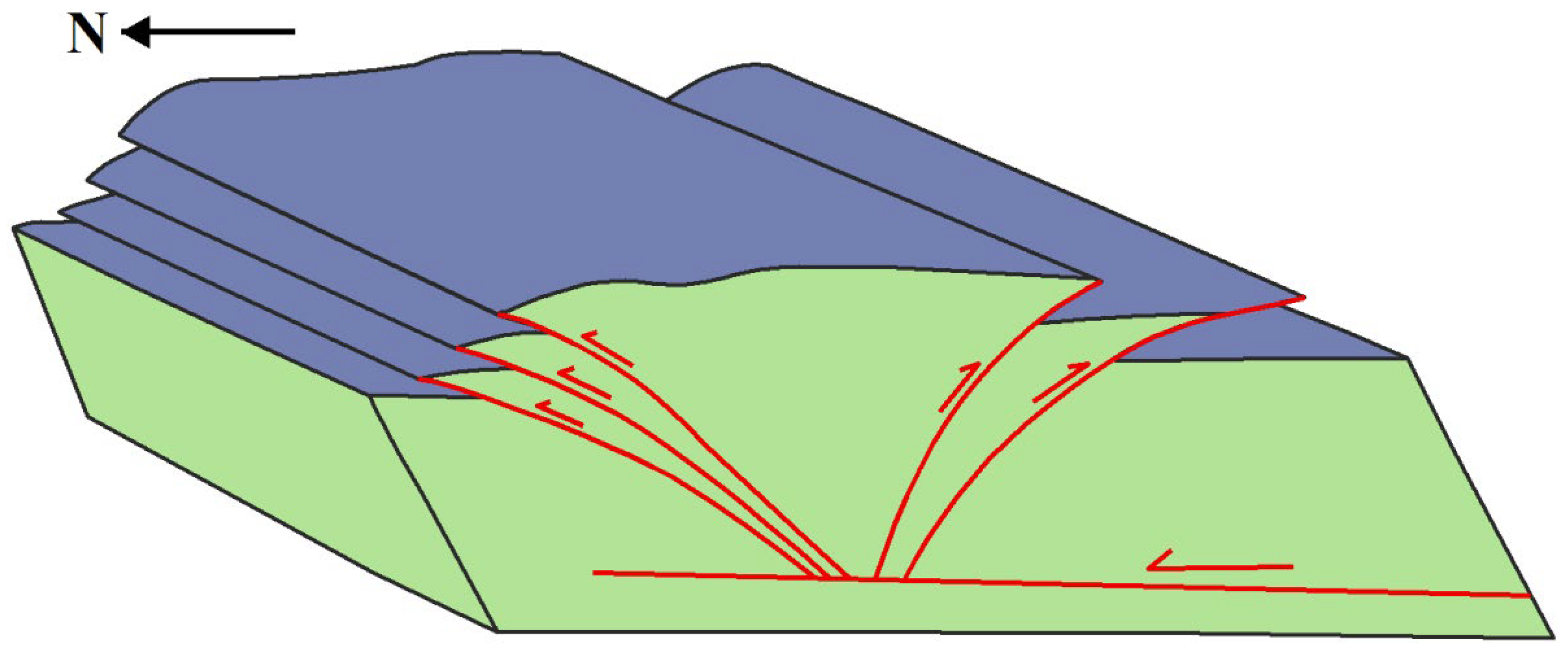
The geometric, kinematic, and topological relationships between faults in the northern Birjand mountain range were determined, with a focus on how these faults have formed geologic structures. The structural style and mechanism of the study area were investigated using field evidence. On the basis of their geometric relationships and kinematics, our research provides a framework for analyzing interacting faults. The Nehbandan fault system has sub-branches in the northern and southern terminals; the northern terminals of the Nehbandan fault are reverse faults with ~WNW–ESE striking (Figure 2). In the northern Birjand mountain range, several east–west trending faults cut through geological units (Figure 3); field evidence indicates high tectonic activity associated with these fault systems. Geometric and kinematic analyses of faults show that some planes of these fault zones have reverse components, which reveal the existence of compressional stress in the study area. In this research, the northern Birjand mountain range was characterized by four main reverse fault planes with nearly E–W striking: the F1, F2, F3, and F4 faults with lengths of 31 km, 17 km, 8 km, and 38 km, respectively. Furthermore, the F1 and F2 reverse fault planes have southward dips, and the F3 and F4 reverse fault planes have northward dips (Table 1). Most uplift in the area is related to the F1 and F3 fault planes, and it can be seen in the field observations and DEM images where these faults connect to the Nehbandan fault system (Figure 4). The F1 fault cut the Upper Cretaceous to Oligocene rock units, the F2 and F3 faults moved the Upper Cretaceous to Quaternary rock units, the F4 fault cut and cut the Neogene and Quaternary rock units, the F5 fault displaced the Upper Cretaceous to Eocene rock units, and the F6 fault displaced the Upper Cretaceous to Quaternary rock units. Moreover, these main reverse fault planes are cut by minor left-lateral strike-slip faults. A review of the faults in the northern Birjand mountain range implies that these reverse fault planes join with the Nehbandan fault system, which is an N–S strike-slip fault. In other words, reverse faults such as F1, F2, F3, and F4 are the continuation and splays of the Nehbandan fault system. The relationships between these faults are relay interactions; these faults with reverse components created high relief structures in the northern Birjand mountain range. The pop-up structure in the N–S direction is suggested, considering the mechanisms and geometry of the faults in the northern Birjand mountain range (Figure 10). Our proposed model for the study area suggests that the NW–SE main branches of the Nehbandan fault system are the source of reverse events on some fault planes in the northern Birjand mountain range.

6. Conclusions

In the northern Birjand mountain range, several nearly east–west striking faults cut through all of the geological units. In this research, we described fault patterns for understanding deformational patterns related to the faults, and we characterized the geometric-kinematic relationships, the displacement direction, and the angles between intersection faults in the study area. According to the findings of this study, the northern Birjand mountain range is characterized by four main fault zones: the F1, F2, F3, and F4 fault zones from north to south, respectively. These four reverse faults, which are preceded by the Nehbandan fault system, were displaced by two main strike-slip faults. Apart from the left-lateral strike-slip planes within the fault zone, structural evidence, such as uplifting, folding, and offset of the rock units on the reverse planes of these fault zones, indicates high tectonic activity. Moreover, these main reverse faults with different dip directions created high relief structures in the study area. The kinematics and geometrics of the reverse planes of the fault zones in the northern Birjand mountain range in the north–south direction suggest a pop-up structure.

Author Contributions

Conceptualization, E.G. and S.M.M.; Data curation, S.M.M.; Formal analysis, M.E.; Funding acquisition, A.R.; Investigation, M.E.; Methodology, M.E. and A.R.; Project administration, E.G. and S.M.M.; Resources, R.D.; Software, M.E.; Supervision, E.G. and S.M.M.; Validation, A.R. and R.D.; Visualization, E.G. and A.R.; Writing—original draft, M.E., E.G., S.M.M. and A.R.; Writing—review & editing, M.E., A.R. and R.D. All authors have read and agreed to the published version of the manuscript.

Funding

This research received no external funding.

Institutional Review Board Statement

Not applicable.

Informed Consent Statement

Not applicable.

Data Availability Statement

Data is contained within the article.

Acknowledgments

This research was conducted in collaboration with the University of Birjand (Iran), the International Institute of Earthquake Engineering and Seismology (Iran), Shahid Bahonar University of Kerman (Iran), and Utrecht University (Netherlands). We appreciate their active participation in this investigation.

Conflicts of Interest

The authors declare no conflict of interest.

References

  1. Jackson, J. Partitioning of strike-slip and convergent motion between Eurasia and Arabia in eastern Turkey and the Caucasus. J. Geophys. Res. Solid Earth 1992, 97, 12471–12479. [Google Scholar] [CrossRef]
  2. Ghanbarian, M.A.; Yassaghi, A.; Derakhshani, R. Detecting a sinistral transpressional deformation belt in the Zagros. Geosciences 2021, 11, 226. [Google Scholar] [CrossRef]
  3. Berberian, M.; King, G. Towards a paleogeography and tectonic evolution of Iran. Can. J. Earth Sci. 1981, 18, 210–265. [Google Scholar] [CrossRef]
  4. Meyer, B.; Le Dortz, K. Strike-slip kinematics in central and eastern Iran: Estimating fault slip-rates averaged over the Holocene. Tectonics 2007, 26, 1–20. [Google Scholar] [CrossRef]
  5. Tirrul, R.; Bell, I.; Griffis, R.; Camp, V. The Sistan suture zone of eastern Iran. Geol. Soc. Am. Bull. 1983, 94, 134–150. [Google Scholar] [CrossRef]
  6. Jackson, J.; McKenzie, D. Active tectonics of the Alpine—Himalayan Belt between western Turkey and Pakistan. Geophys. J. Int. 1984, 77, 185–264. [Google Scholar] [CrossRef]
  7. Walker, R.; Khatib, M. Active faulting in the Birjand region of NE Iran. Tectonics 2006, 25, 1–17. [Google Scholar] [CrossRef]
  8. Şengör, A.; Altıner, D.; Cin, A.; Ustaömer, T.; Hsü, K. Origin and assembly of the Tethyside orogenic collage at the expense of Gondwana Land. Geol. Soc. Lond. Spec. Publ. 1988, 37, 119–181. [Google Scholar] [CrossRef]
  9. Samimi, S.; Gholami, E.; Khatib, M.; Madanipour, S.; Lisker, F. Transpression and exhumation of granitoid plutons along the northern part of the Nehbandan fault system in the sistan suture zone, Eastern Iran. Geotectonics 2020, 54, 130–144. [Google Scholar] [CrossRef]
  10. Comijany, N.A.; Khatib, M.M.; Gholami, E.; Shabestari, G.M.; Zarrinkoub, M.H. Estimation of shortening and vergence in northern part of Sistan Suture Zone for determination of kinematic convergent vectors. J. Adv. Appl. Geol. 2019, 9, 232–255. [Google Scholar] [CrossRef]
  11. Mousavi, Z.; Walpersdorf, A.; Walker, R.; Tavakoli, F.; Pathier, E.; Nankali, H.; Nilfouroushan, F.; Djamour, Y. Global Positioning System constraints on the active tectonics of NE Iran and the South Caspian region. Earth Planet. Sci. Lett. 2013, 377, 287–298. [Google Scholar] [CrossRef]
  12. Baniadam, F.; Shabanian, E.; Bellier, O. The kinematics of the Dasht-e Bayaz earthquake fault during Pliocene-Quaternary: Implications for the tectonics of eastern Central Iran. Tectonophysics 2019, 772, 228218. [Google Scholar] [CrossRef]
  13. Taghipour, K.; Khatib, M.M.; Heyhat, M.; Shabanian, E.; Vaezihir, A. Evidence for distributed active strike-slip faulting in NW Iran: The Maragheh and Salmas fault zones. Tectonophysics 2018, 742, 15–33. [Google Scholar] [CrossRef]
  14. Ezati, M.; Gholami, E. Neotectonics of the Central Kopeh Dagh drainage basins, NE Iran. Arab. J. Geosci. 2022, 15, 992. [Google Scholar] [CrossRef]
  15. Ezati, M.; Agh-Atabai, M. Estimating rate of tectonic activity in central Kopeh dagh using morphometric indices. J. Tethys 2014, 2, 314–326. [Google Scholar]
  16. Bhattacharyya, K.; Dwivedi, H.V.; Das, J.P.; Damania, S. Structural geometry, microstructural and strain analyses of L-tectonites from Paleoproterozoic orthogneiss: Insights into local transport-parallel constrictional strain in the Sikkim Himalayan fold thrust belt. J. Asian Earth Sci. 2015, 107, 212–231. [Google Scholar] [CrossRef]
  17. Vera, E.R.; Mescua, J.; Folguera, A.; Becker, T.; Sagripanti, L.; Fennell, L.; Orts, D.; Ramos, V.A. Evolution of the Chos Malal and Agrio fold and thrust belts, Andes of Neuquén: Insights from structural analysis and apatite fission track dating. J. S. Am. Earth Sci. 2015, 64, 418–433. [Google Scholar] [CrossRef]
  18. Ghanbarian, M.A.; Derakhshani, R. The folds and faults kinematic association in Zagros. Sci. Rep. 2022, 12, 8350. [Google Scholar] [CrossRef]
  19. Yassaghi, A.; Madanipour, S. Influence of a transverse basement fault on along-strike variations in the geometry of an inverted normal fault: Case study of the Mosha Fault, Central Alborz Range, Iran. J. Struct. Geol. 2008, 30, 1507–1519. [Google Scholar] [CrossRef]
  20. Bose, S.; Das, A.; Samantaray, S.; Banerjee, S.; Gupta, S. Late tectonic reorientation of lineaments and fabrics in the northern Eastern Ghats Province, India: Evaluating the role of the Mahanadi Shear Zone. J. Asian Earth Sci. 2020, 201, 104071. [Google Scholar] [CrossRef]
  21. Shi, G.; Shen, C.; Zattin, M.; Wang, H.; Yang, C.; Liang, C. Late Cretaceous-Cenozoic exhumation of the Helanshan Mt. Range, western Ordos fold-thrust belt, China: Insights from structural and apatite fission track analyses. J. Asian Earth Sci. 2019, 176, 196–208. [Google Scholar] [CrossRef]
  22. Zebari, M.; Balling, P.; Grützner, C.; Navabpour, P.; Witte, J.; Ustaszewski, K. Structural style of the NW Zagros Mountains and the role of basement thrusting for its Mountain Front Flexure, Kurdistan Region of Iraq. J. Struct. Geol. 2020, 141, 104206. [Google Scholar] [CrossRef]
  23. Ezati, M.; Gholami, E.; Mousavi, S.M. Paleostress regime reconstruction based on brittle structure analysis in the Shekarab Mountain, Eastern Iran. Arab. J. Geosci. 2020, 13, 1232. [Google Scholar] [CrossRef]
  24. Ezati, M.; Gholami, E.; Mousavi, S.M. Tectonic activity level evaluation using geomorphic indices in the Shekarab Mountains, Eastern Iran. Arab. J. Geosci. 2021, 14, 385. [Google Scholar] [CrossRef]
  25. Camp, V.; Griffis, R. Character, genesis and tectonic setting of igneous rocks in the Sistan suture zone, eastern Iran. Lithos 1982, 15, 221–239. [Google Scholar] [CrossRef]
  26. Rashidi, A.; Abbassi, M.-R.; Nilfouroushan, F.; Shafiei, S.; Derakhshani, R.; Nemati, M. Morphotectonic and earthquake data analysis of interactional faults in Sabzevaran Area, SE Iran. J. Struct. Geol. 2020, 139, 104147. [Google Scholar] [CrossRef]
  27. Rashidi, A.; Kianimehr, H.; Shafieibafti, S.; Mehrabi, A.; Derakhshani, R. Active faults in the west of the Lut block (Central Iran). Geophys. Res. 2021, 22, 70–84. [Google Scholar] [CrossRef]
  28. Freund, R. Rotation of strike slip faults in Sistan, southeast Iran. J. Geol. 1970, 78, 188–200. [Google Scholar] [CrossRef]
  29. Rashidi, A.; Khatib, M.M.; Derakhshani, R. Structural Characteristics and Formation Mechanism of the Earth Fissures as a Geohazard in Birjand, Iran. Appl. Sci. 2022, 12, 4144. [Google Scholar] [CrossRef]
  30. Khatib, M. Structural Analysis of Southern Birjand Mountains. Ph.D. Thesis, Shahid Beheshti University, Tehran, Iran, 1998. [Google Scholar]
  31. Rashidi, A.; Khatib, M.M.; Nilfouroushan, F.; Derakhshani, R.; Mousavi, S.M.; Kianimehr, H.; Djamour, Y. Strain rate and stress fields in the West and South Lut block, Iran: Insights from the inversion of focal mechanism and geodetic data. Tectonophysics 2019, 766, 94–114. [Google Scholar] [CrossRef]
  32. Rashidi, A.; Derakhshani, R. Strain and Moment-Rates from GPS and Seismological Data in Northern Iran: Implications for an Evaluation of Stress Trajectories and Probabilistic Fault Rupture Hazard. Remote Sens. 2022, 14, 2219. [Google Scholar] [CrossRef]
  33. Allmendinger, R.W. FaultKin 8 Program. Available online: https://www.rickallmendinger.net/ (accessed on 12 February 2022).
  34. Berberian, M.; Yeats, R.S. Patterns of historical earthquake rupture in the Iranian Plateau. Bull. Seismol. Soc. Am. 1999, 89, 120–139. [Google Scholar]
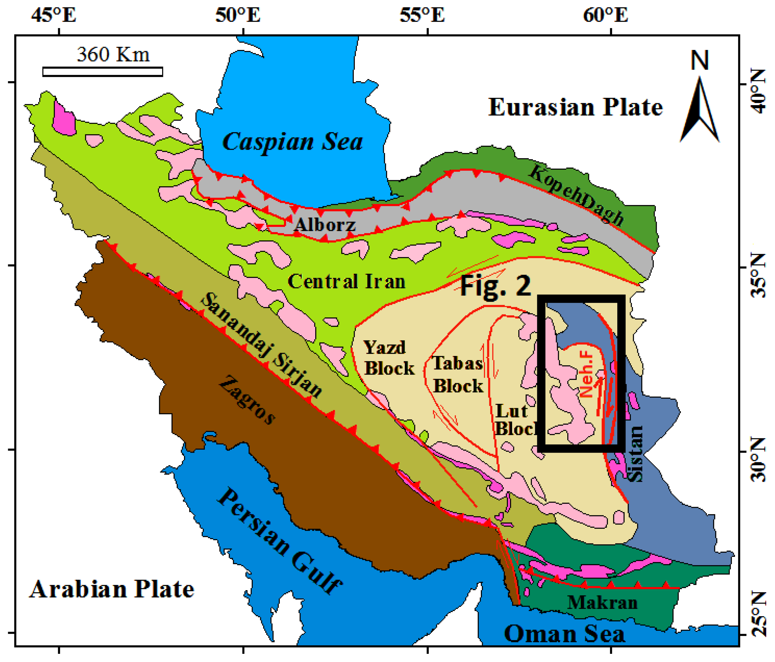
Figure 1. The structural zones of Iran. The black rectangle shows the area where the study took place (Neh. F = Nehbandan fault).
Applsci 12 06625 g001
Figure 2. Structural map of eastern Iran (Sistan suture zone) on a shaded relief map, Neh = Nehbandan fault.
Applsci 12 06625 g002
Figure 3. Digital elevation model structural map of the tectonic features. The orientation of the principal stress axes associated with faults is represented by stereonets.
Applsci 12 06625 g003
Figure 4. Geological map of the northern Birjand mountain range.
Applsci 12 06625 g004
Figure 5. (a) Trace of the reverse, dextral component of the F1 fault (shown by triangles); (b) slicken line on the minor fault (the location is shown by the star). In the stereonet, the numbers 1, 2, and 3 represent the orientation of the principal stress axes, and the arrow in the stereonet indicates the direction of movement of the hanging wall.
Applsci 12 06625 g005
Figure 6. (a) Field photo of F2 fault trace (shown by triangles) that is reverse with a dextral strike-slip mechanism; (b) slicken line on the minor fault (the location is shown by the star). Numbers 1, 2, and 3 in the stereonet denote the orientation of the principal stress axes; the arrow in the stereonet indicates the movement direction of the hanging wall.
Applsci 12 06625 g006
Figure 7. (a) Field photo illustrating the uplift in phyllite rocks by F3 fault (shown by triangles); (b) the trace of F3 fault with a closer view, which is a reverse fault with a sinistral component; (c) slicken line on the minor fault in part. Numbers 1, 2, and 3 in the stereonet denote the orientation of the principal stress axes; the arrow in the stereonet indicates the movement direction of the hanging wall.
Applsci 12 06625 g007
Figure 8. (a) Trace of F4 fault which is a reverse fault with a sinistral strike-slip component on the satellite image (shown by triangles); (b) field photo illustrating the uplift in Neogean sediments by F4 fault; (c) slicken line on the minor fault (the location is shown by a star); numbers 1, 2, and 3 in the stereonet denote the orientation of the principal stress axes; (d) nearly 40 m offset and tilting of rivers along the fault, arrow in the stereonet indicates the movement direction of hanging wall.
Applsci 12 06625 g008
Figure 9. (a) Field photo of F7 fault with dextral mechanism, the trace is shown by triangles; (b) slicken line on the minor fault. In the stereonet, the numbers 1, 2, and 3 represent the orientation of the principal axes of stress.
Applsci 12 06625 g009
Figure 10. A schematic model of the pop-up structure for the study area in the north–south direction.
Applsci 12 06625 g010
Table 1. The kinematic and geometric location of faults identified in the study region.
Fault
Name
Geometric
Position
Slicken Line
Position
Fault
Mechanism
F1N90E, 50SS88E, 70Reverse with a dextral component
F2N84E, 50SS28E, 48Reverse with a dextral component
F3N90E, 60NN21E, 58Reverse with a sinistral component
F4N85E, 40NN2E, 39Reverse with a sinistral component
F5N10W, 50NEN4W, 8Sinistral with a normal component
F6N60W, 78SWN76W, 19Sinistral with a reverse component
F7N80E, 86SEN80E, 11Dextral with a reverse component
Publisher’s Note: MDPI stays neutral with regard to jurisdictional claims in published maps and institutional affiliations.