Abstract
This paper presents a high-precision transfer system of time and RF frequency via the fiber optic link based on secure encryption. On the basis of the two-way time transfer of optical fiber, a security strategy composed of an SM2 encryption algorithm is introduced, which can resist the security risk of time information being tampered with. The experimental results show that the developed picosecond-precision fiber-optic time transfer equipment can ensure high stability while realizing the encryption function. Time synchronization stability in terms of time deviation (TDEV) of 1 PPS can reach around 10.7 ps at 1 s and 7.1 ps at 10 s averaging time. The stability of the 10 MHz frequency can reach around 4.7 × 10⁻¹² at 1 s and 1.1 × 10⁻¹² at 10 s averaging time. There is no significant difference in time transfer accuracy, compared with unencrypted conditions. Furthermore, this paper realizes a ring time transfer network via a 150 km fiber-optic link with three nodes using three devices. The TDEV of 1PPS can reach around 20.8 ps at 1s averaging time. This paper provides a reference to establish a high-precision, safe, and stable time synchronization fiber network in the future.
1. Introduction
With the rapid development of modern atomic clock technology, the uncertainty of the strontium atomic clock can reach 10−18 magnitude and the stability can reach 10−19 magnitude [1,2,3,4]. In order not to deteriorate the performance of high-precision time–frequency standards, a more precise time–frequency transfer technique is needed [5,6]. The existing time transfer system includes a network, global navigation satellite systems (GNSS), optical fiber, and other schemes [7,8]. Network timing is the most common application, but the synchronization level is in the microsecond level, which cannot meet the needs of high-precision time users. Although GNSS can be used across continents, the synchronization accuracy is only at the nanosecond. The synchronization precision of the optical fiber can reach the picosecond level, and it also has the advantages of a stable transmission medium and anti-electromagnetic interference [9]. Time transfer via optical fiber is one of the most accurate timing technologies at present [10,11]. It is also an important research direction of high-precision time transfer technology, and many scientific research institutions around the world have carried out research and testing in this field. In 2009, the Swedish SP Institute achieved a long-term average result of optical timing with less than 1 ns for over a 560 km optical link [12]. The time synchronization accuracy of PLA University of Science and Technology was less than 500 ps at 125 km [13]. In 2013, The long-term stability was less than 20 ps in the 540 km fiber link test at Paris Observatory, France [14]. In 2014, Tsinghua University achieved a peak-to-peak time synchronization of less than 100 ps over an 80 km field fiber link [15]. In 2020, the National Time Service Center completed the optical fiber time transfer test on the 1085 km field optical fiber link. Additionally, the time synchronization stability was about 5.4 ps/40,000 s [16]. In 2021, the time synchronization system of two-way time-division multiplexing on the same fiber and same wave transmission was used on a field optical fiber link with a length of about 60 km and stability of less than 16 ps/s and 7 ps/10,000 s in Shanghai Jiaotong University [17].
National security departments reported that attacks and theft of secrets in the field of key information infrastructure occur from time to time. Although optical fiber has the advantages of a stable transmission medium and anti-electromagnetic interference, the developing optical fiber timing technology also faces certain information security challenges, such as attacks, deception, etc. Some technologies of time transfer via optical fiber rely on the transmission of physical signals, but they also require a certain amount of information transmission, for example, the transmission of information such as the real-time measurement of the time delay between the time source and the user. A method of transferring time information is to use the WDM technique [18]. The improved IRIG-B time code carries the IRIG code information, as well as the delay difference information [19]. Two-way time transfer via optical fiber also needs to transfer the time difference between two optical fiber links, which can complete the calculation and compensation of the time difference between the clock of two sites [20]. These methods have the risk of being cracked and attacked. It will inevitably affect the control of time delay if the information is tampered with. This will be an unavoidable problem for the wide application of optical fiber time synchronization systems in the future. However, there is relatively little research in this area at present.
Based on this security risk, in order to prevent the attacker from tampering with the link transmission delay information, this paper introduces the asymmetric encryption SM2 algorithm [21] to form a security strategy on the basis of two-way time transfer via an optical fiber scheme. The time delay data of the optical fiber are safely protected to resist the hidden danger that the information is tampered with. After testing, the developed two-way time transfer via optical fiber equipment realizes the encryption function, in addition to ensuring the accuracy of optical fiber time transfer. The measured stability of time transfer is less than 10.7 ps at 1 s and 7.1 ps at 10 s. The stability of frequency 10 MHz is less than 4.7 × 10⁻¹² at 1 s and 1.1 × 10⁻¹² at 10 s. At the same time, this paper uses three devices to build a ring timing network, which can demonstrate the networked optical fiber time cascade transmission system. The standard deviation of time synchronization measured by the ring timing network is 3.1 × 10⁻¹¹, and the TDEV is 2.1 × 10⁻¹¹ at 1 s, which can ensure the safety of the system while the system still has high accuracy.
2. Methods
2.1. Basic Principle of Safety Optical Fiber Time Transfer Equipment
The optical fiber time transfer equipment developed in this paper is based on the two-way time transfer method [22] using optical fiber. This method can overcome the asymmetry of the transmission link. The basic principle is that the pulse signal, frequency signal, and time information of a clock source from a local site are sent to a remote site. The remote site also needs to send pulse signal, frequency signal, and time information to the local site while receiving the time–frequency signal sent by the opposite site. By measuring the time difference between the pulse signals sent by the local and remote sites, the clock difference between the two sites is calculated. The clock difference is used to adjust the phase of the remote site equipment based on the local site equipment, which can realize the time synchronization of the two sites. Before the time information is transmitted from the local to the remote site, the time difference information measured by the time interval counter (TIC) of the local site is encrypted, while the decryption comparison is completed at the remote site. This can realize a secure optical fiber time transmission scheme, as shown in Figure 1. Tx stands for the laser transmitter, and Rx stands for the optical receiver of small form-factor pluggable (SFP). TIC stands for measuring the signals at both sides of the link using time interval counters. λ1 is the wavelength of the fiber forward propagation. Additionally, λ2 is the wavelength of the fiber backward propagation.
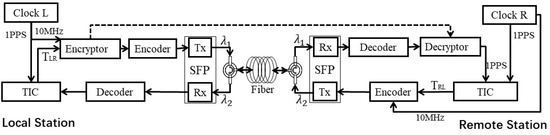
Figure 1.
Schematic diagram of a safety optical fiber time transfer.
The time difference information measured by the TIC of the local site is encrypted. One way the encrypted information is sent to the remote site is via the external sending unit. Additionally, the other way is modulated to Tx of the SFP laser at the local site through intensity modulation, which is connected to the optical fiber through the circulator. The encrypted information transmits to the remote site equipment via the optical fiber. The encrypted information is received using Rx of SFP and decoded through a decoder at the remote site. Then, the data of the optical fiber link are decrypted and compared with the data received by the external unit with a decryption unit and the main control unit. If the data are the same, the clock difference is calculated and synchronized by using Formula (3). The remote site equipment transfers 1 PPS and 10 MHz signals, along with , to the local site equipment using the same optical fiber through the circulator. The local site equipment uses an ultra-high precision TIC to measure the 1 PPS signal from the remote site and the local reference 1 PPS signal to obtain the result , as shown in Formula (1). The remote site compares the 1 PPS signal from the local site with the 1 PPS signal held by the remote site to obtain data , as shown in Formula (2).
where and are, respectively, two-way time comparison results measured by the local site and the remote site equipment. and are time-delay values at the local- and remote-site-sending units of the equipment. are time-delay values of the receiving unit at the local and remote sites, respectively. are, respectively, the time transfer delay of the signal from the local to the remote site and from the remote to the local site in the optical fiber link.are calibration in advance. is the time difference value between the local and remote sites by the system. The remote site calculates and compensates according to Formula (3), so as to realize the synchronization between the remote and the local site.
At present, the data are plaintext measured via the TIC unit in some optical fiber time transfer systems. Thus, there is a risk that an attacker can tamper with it. The remote site will receive the wrong data if the information is tampered with. An error will occur in the time transfer if compensation for the time difference is implemented. For example, if the comparison data at the local site are added with a time offset of 10 ns, the time signal output at the remote side will have a leading offset of 5 ns. The error is difficult to find and prevent independently through the remote site, which will bring security risks to the related applications of time service.
The plaintext is usually used for information exchange in optical fiber time transfer technology. In this paper, security protection encryption was carried out for data to avoid the situation in which plaintext is tampered with. Firstly, an experiment using single optical fiber safety time transfer equipment was completed. Then, a network system of time synchronization was built by using three safety time synchronization devices and a ring timing scheme. The three safe time synchronization nodes were linked through an optical fiber link. Lastly, the local and remote sites were configured with encryption and decryption units to form a safe optical fiber safe time transfer system for realizing the safe networking of the whole optical fiber time synchronization network. There was no significant difference in time and frequency transfer accuracy compared with those of the unencrypted case.
2.2. Basic Principle of Encryption Method
There are a variety of encryption algorithms. In this study, many encryption algorithms were investigated. The SM2 algorithm was selected to verify the feasibility of the encryption algorithm. However, the encryption algorithm is not limited to this. The SM2 algorithm is a reliable, small amount calculation encryption algorithm, which can be combined with optical fiber time transfer characteristics. The public key of the SM2 algorithm can be used to encrypt, and the private key can be used to decrypt. Moreover, the public key is public, and the secret key is kept by the user. Compared with the traditional symmetric encryption algorithm, the SM2 algorithm does not need to synchronize the secret key through a reliable channel in advance. The longer the key length, the harder it is to crack.
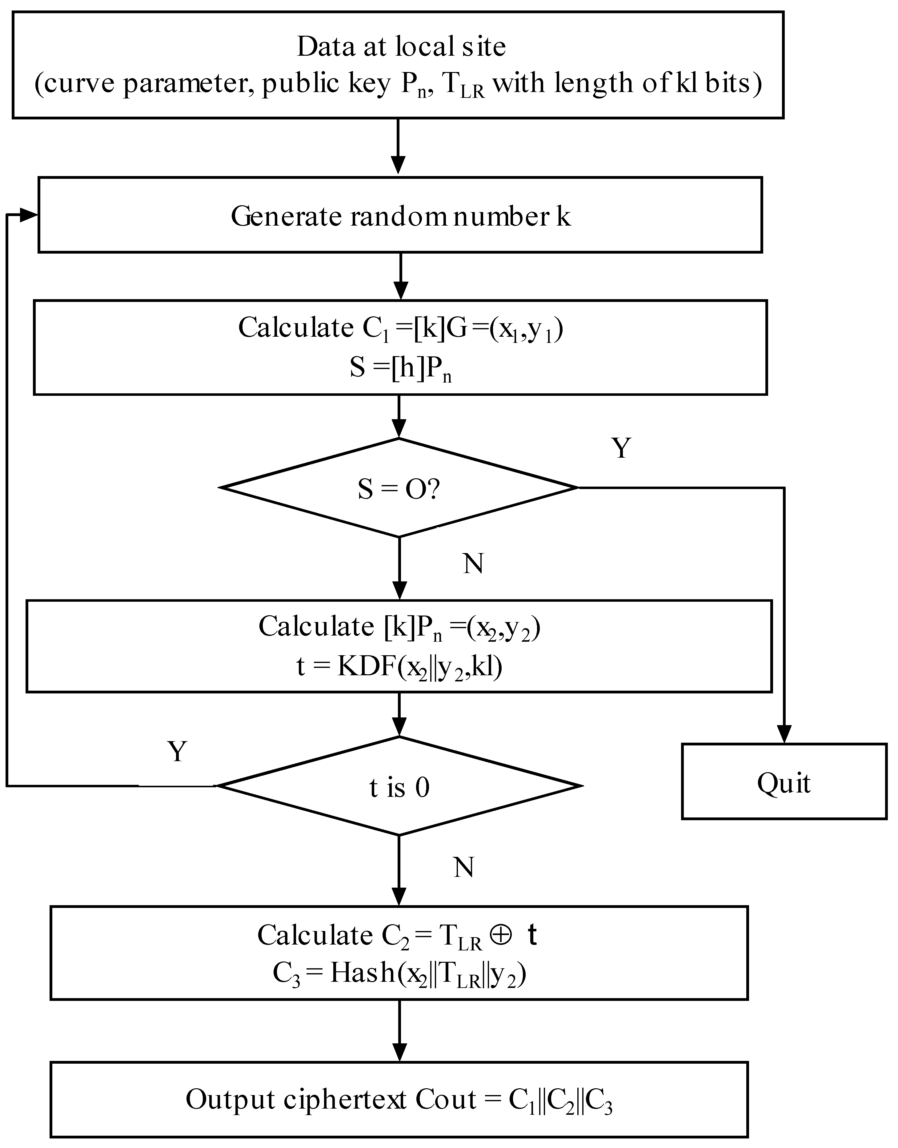
The time difference information of the optical fiber time transfer to the remote site by the local site of safety is . kl is the data length of the. The plaintext is executed to encrypt following the operation step at the local site. Firstly, the SM2 encryption algorithm generates a random number K. Then, the elliptic curve point (x1, y1) is obtained by performing a point doubling operation on K. At the same time, the elliptic curve point S is obtained by using the public key to perform the point doubling operation. If S is an infinite point, an alarm is given and quit. If S is not a point at infinity, the elliptic curve point (x2, y2) is obtained by performing a point doubling operation using the public key. A value of t is obtained by operating that coordinate value with the key derived function (KDF). If the value of t is all 0, the step of generating the random number k is performed again. If t is not 0, the value C2 will be calculated by the time difference value and t based on XOR operation. The value C3 is computed through the cryptographic Hash () function. The ciphertext C_out is obtained by C1, C2, and C3. The flowchart of the encryption algorithm is shown in Figure 2.
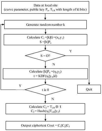
Figure 2.
SM2 encryption algorithm.
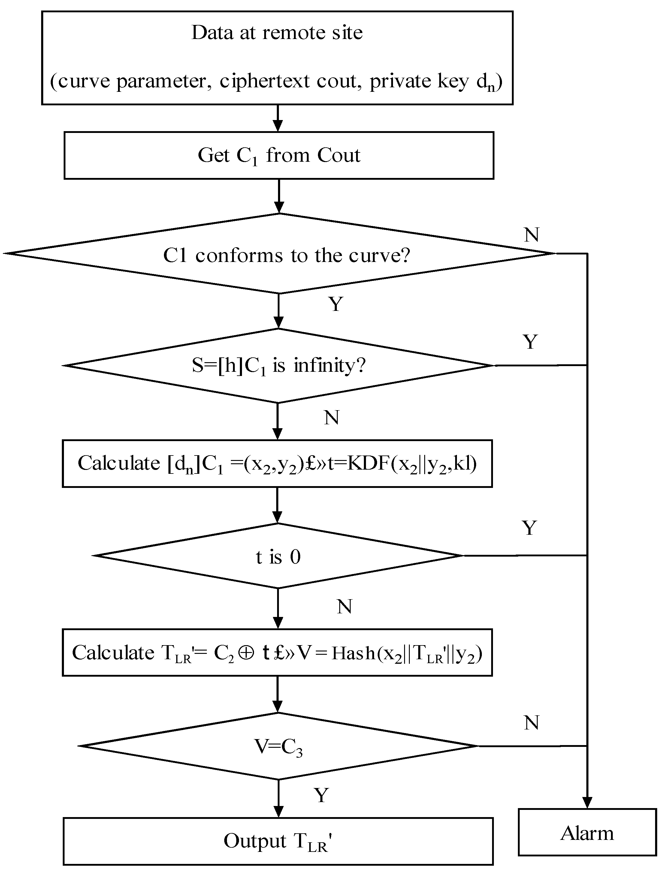
After the encryption process is completed, the information is transmitted and decrypted to the secure optical fiber time transfer equipment at the remote site. The decryption algorithm flow is shown in Figure 3. In order to decrypt the ciphertext Cout, the following steps should be performed as a remote side decryption unit.

Figure 3.
SM2 decryption algorithm.
First, the string C1 is taken out from Cout. Additionally, C1 is used to verify whether it conforms to the elliptic curve equation. If not, it sends an alarm and exits. If it conforms, the curve point S is computed using C1. After the calculation is completed, S is judged as to whether it is an infinite point. If S is an infinite point, an alarm is given, and the system exits. If S is not a point at infinity, then C1 is used to calculate the coordinate point (x2, y2). Additionally, it calculates that coordinate point by using KDF to obtain the string t. If the bit string t is all 0, it sends an alarm and exits. If not, the corresponding value C2 is obtained from Cout. TLR′ is obtained by performing XOR operation on C2 and t. Finally, a cryptographic hash function is used to compute the value of V. The C3 is taken from Cout. If V is equal to C3, the desired plaintext TLR′ is output.
As shown in Table 1, the SM2 algorithm has advantages in both security and speed performance. The 256-bit SM2 password strength is equivalent to the 3072-bit RSA password strength. The security period is 2040 years. Stronger keys take longer to crack. They also take longer to encrypt and decrypt between devices. Therefore, in this study, we chose the encryption algorithm with the key strength of 256 of the SM2 algorithm. While ensuring the security of the system, it can quickly complete the process of information encryption or decryption and the task of transfer.

Table 1.
The table of key strength values.
The experiment was completed on a calibrated local unencrypted device to obtain the time interval measurement data . It changed the data to zero. Then, the zero value was sent to the remote device to complete the time synchronization test. It was found that the time at the remote site existed /2 of the lead offset.
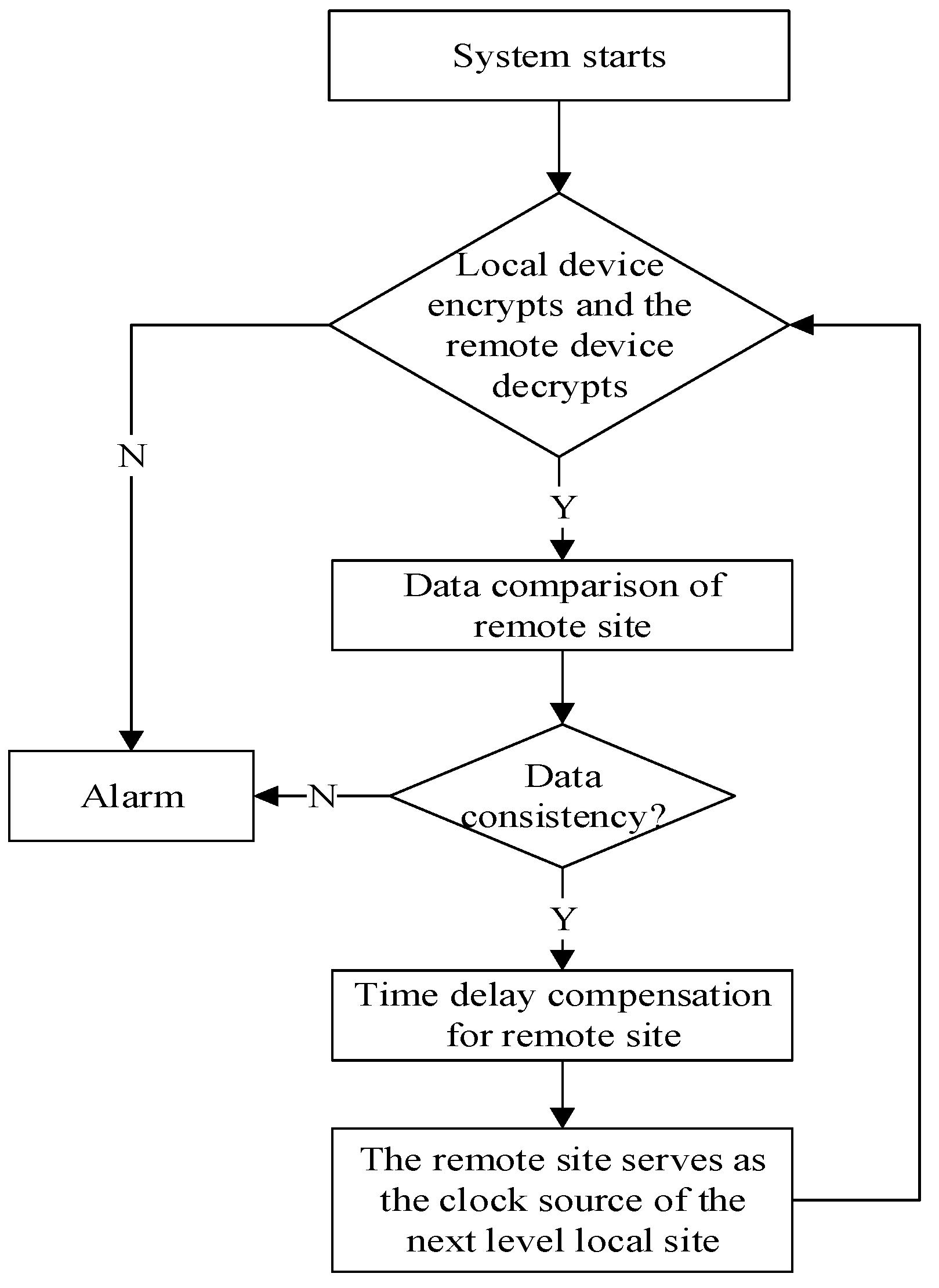
The optical time transfer link before encryption can complete the time synchronization function independently. However, an attacker can tamper with the plaintext of the intuitive time-delayed data. In this paper, the optical fiber security time transfer equipment with an encryption unit was used in the experiment. The data transmitted to the remote site were ciphertext, which is not easy to tamper with. In order to verify the feasibility of the algorithm in this paper, by means of external injection, the data encrypted by the SM2 algorithm were transmitted to the decryption unit of the remote site. Through the external connection line, the security optical fiber time transfer equipment of the local site is connected with the remote site. After the normal operation of the encryption and decryption units, the secure optical time transfer system can perform time delay compensation to achieve synchronization. If the optical fiber link is disconnected or the data are not the same, the transmission system defaults to an external attack. At this time, the security optical fiber time transfer equipment fails synchronously. The equipment cannot complete the compensation function of the optical fiber link. At this time, the alarm function is enabled. Security personnel performs a security check of the link and the device. The alarm flow of abnormal operation of safety equipment is shown in Figure 4.
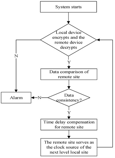
Figure 4.
Flowchart of alarm for optical fiber time transmission safety equipment.
3. Experiment
3.1. Experiment and Analysis of Single Safety Optical Fiber Timing Equipment
In this study, the SM2 algorithm was used to generate a pair of keys. A public key is distributed to the local site device, while a private key is distributed to the remote site device. Then, the data of the fiber-optic time transfer system are encrypted. Additionally, the data are sent to the remote site for decryption through the externally injected link. The decrypted data are compared with the time difference data transmitted to the remote site via the optical fiber link. If the data are the same, the time synchronization of the system is completed according to Formula (3). Finally, we used an evaluation device SR620 to test the performance of the synchronization. As long as the private key of the user at the remote site is not leaking, it is difficult for a third party to decrypt the content information even if it intercepts the ciphertext.
The experiments were performed on a safety optical fiber system based on standard small form-factor pluggable (SFP) optical transceivers. The single-mode SFPs were operated at the wavelength of about 1550 nm. The local safety device and the remote safety device were connected by using two SFPs with high stability but different wavelengths linked to an optical circulator. In this study, two adjacent channels C42 and C43 were selected. The wavelength of the C42 channel was 1543.730 nm, and the wavelength of the C43 channel was 1542.956 nm. Additionally, the transmission rate was 1.25 Gb/s. The 1PPS signal and 10 MHz signal input by the clock source and the time interval information were encrypted and encoded using the local site equipment. Then, they were modulated to the local SFP by means of intensity modulation. After the laser was connected to the local circulator, the data were sent to the safety equipment at the remote site through 50 km of optical fiber. At that same time, the security device at the remote site passed through the circulator, connected to a photodetector. The photodetector detected the signal from the local terminal. The remote site converted and divided the signal into two paths. A 10 MHz carrier signal was obtained through a carrier recovery module. The signal was purified through a phase-locked loop (PLL) to be used as a clock source of a time-keeping module in the safety equipment at the remote site. At the same time, the purified and stable 1PPS time signal was output. The other path demodulated the 1PPS signal and the encrypted information transmitted from the local site. The encrypted information was decrypted using a decryption unit. Two channels of 1PPS signals were calculated via the TIC module to obtain TRL. The decrypted data were calculated via the operation control unit by using Formula (3) to obtain a comparison result. Additionally, time-delay compensation was performed using the delay phase control unit. In this way, the system realized the two-way time transfer of the optical fiber link. Additionally, the remote site output a synchronous 1 PPS signal and a 10 MHz signal.
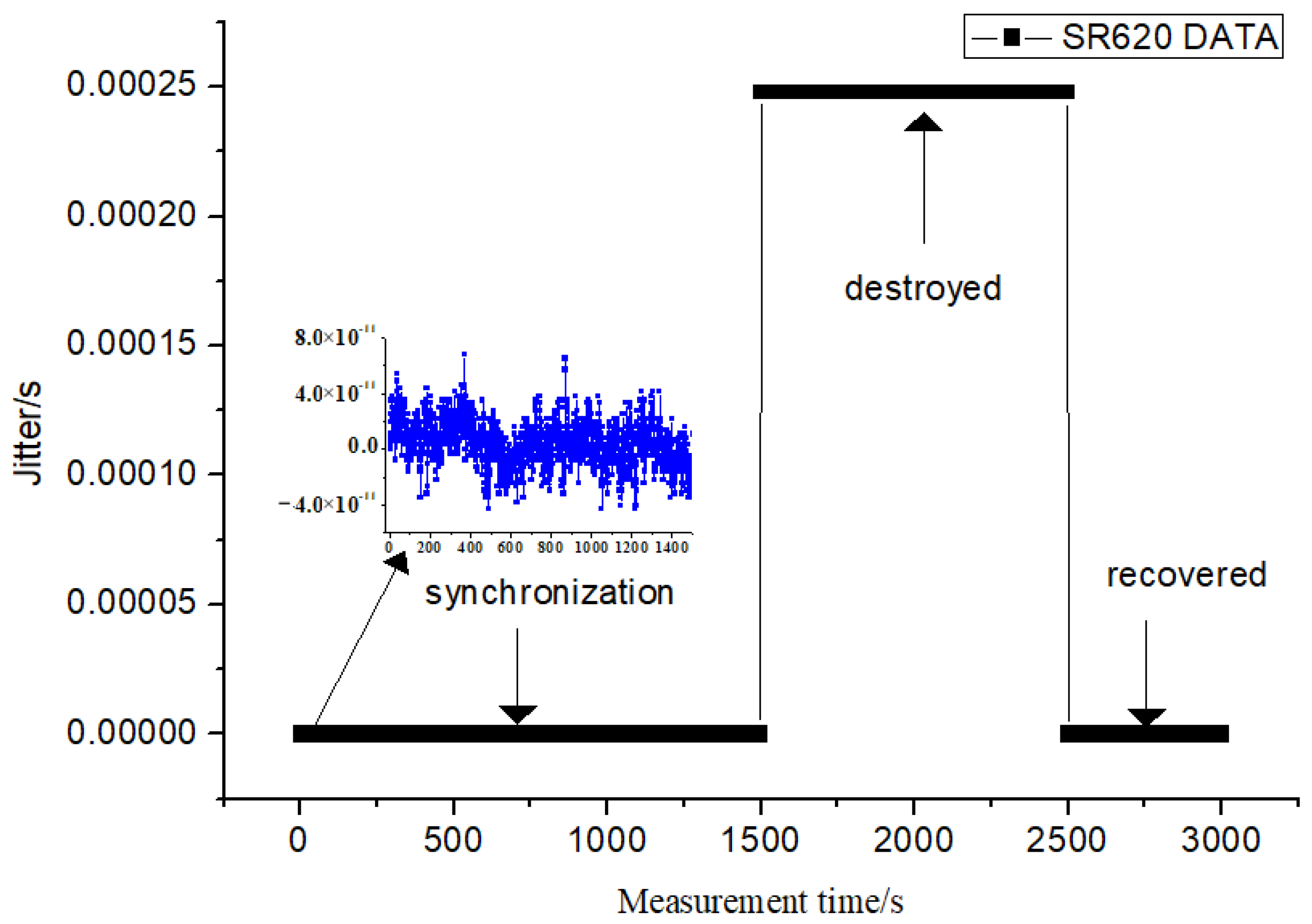
In order to verify the feasibility of the algorithm, we used an external injection to transfer the data encrypted by the SM2 algorithm to the decryption unit of the remote security device through the external connection line. The decrypted data were compared with the data transfer through the optical fiber link. If the decrypted data were consistent, the time synchronization was completed. A time interval counter SR620 was used to collect data. It can observe the synchronization effect of the optical fiber time transfer system before and after the security encryption unit is destroyed. Once ciphertext is tampered with, the device immediately finds it and sends an alarm. The data for a total of 3000 s were collected, as shown in Figure 5. During the safe operation of 1500 s, the data of SR620 were observed. It was found that the peak-to-peak value of time synchronization was within 100 ps. The ciphertext data were tampered with, and it was found that the synchronization was invalid. After 1000 s of keeping and collecting, the delay of the optical fiber link was not compensated. Additionally, the time difference collected using the SR620 was about 250 µs. Lastly, the time synchronization was restored when the tampered part was repaired. Additionally, the normal operation acquisition was observed again for 500 s.

Figure 5.
Comparison of system synchronization of before and after the encryption was damaged.
3.2. Experimental Test
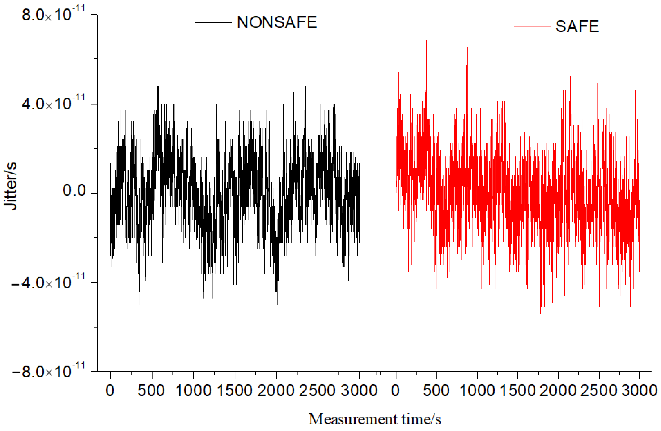
In the experiment, the time stability of the equipment before and after encryption was compared. A single secure optical time transfer device was verified via a 50 km optical fiber link. The data before and after the use of the encryption SM2 algorithm were collected. The synchronization effects and TDEVs of a single secure device and a single non-encrypted device are shown in Figure 6 and Figure 7.
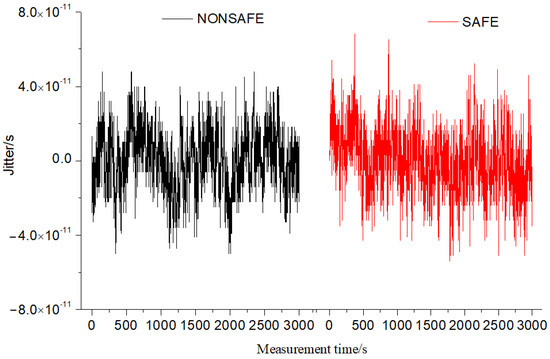
Figure 6.
Comparison of delay jitter data of single equipment.
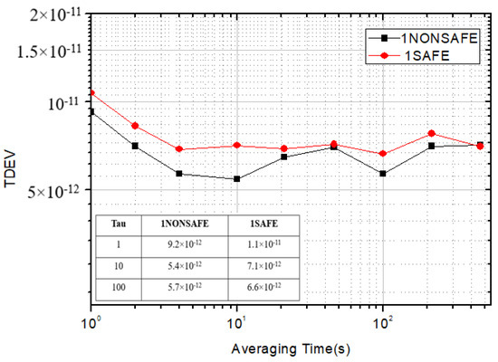
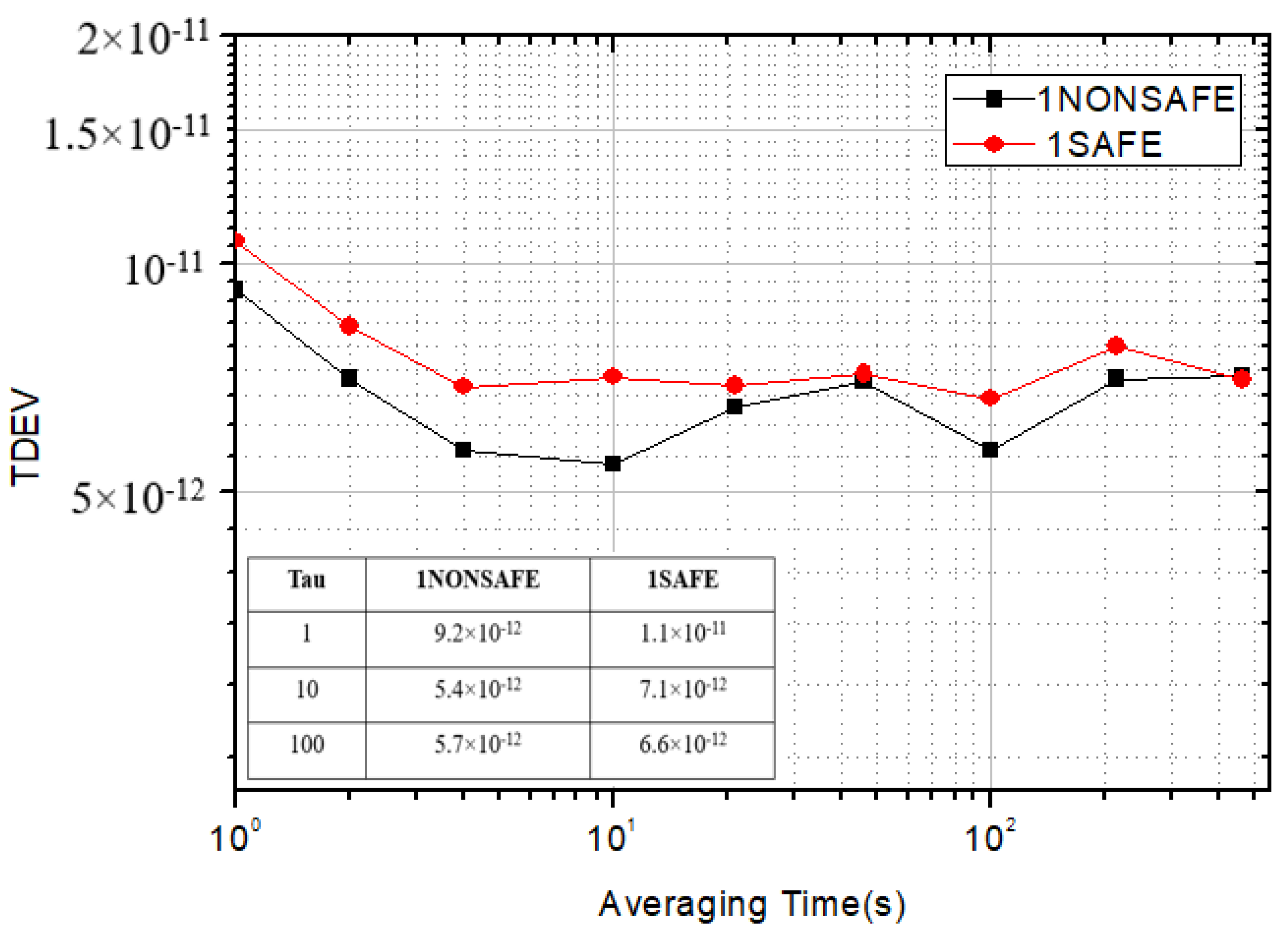
Figure 7.
TDEV comparison chart of single equipment.
3.3. Result and Discussion
As shown in Figure 7, data were acquired on a single optical fiber time transfer device by sampling for 3000 s. Before the security encryption scheme, the standard deviation of a single optical fiber time transfer system was 1.1 × 10⁻¹¹. The peak-to-peak value of jitter was 104 ps. Additionally, the stability TDEV was 9.2 × 10⁻¹² at 1 s. After introducing the security encryption scheme, the standard deviation of a single device was 1.7 × 10⁻¹¹. The peak-to-peak value of jitter was 120 ps, and the stability TDEV was 10.7 × 10⁻¹² at 1 s. According to the test data, it was found that there was no significant difference in indicators when the security encryption method was introduced into a single device to ensure system security. A single secure optical time transfer system was validated on a 50 km optical link, and the encryption algorithm data were collected, as shown in Table 2. Before encryption, the plaintext data of the link delay from the local to the remote site through 50 km optical fiber were 249,746,186 ps. The 256-bit SM2 algorithm was used to encrypt the public key and the generated random number K to obtain the ciphertext C_out. After being encoded and modulated to the laser, it was sent to the remote site equipment through the optical fiber link. After decoding, the remote device used the corresponding private key to decrypt. It was found that the data after encryption were the same as those with plaintext before encryption. According to the calculation results of the algorithm test, the encryption time was about 130 µs. Additionally, the decryption time was about 150 µs.
Table 2.
Encryption and decryption data table via 50 km optical fiber link.
4. Cascade Experiment
4.1. Basic Principle of Ring Network Test
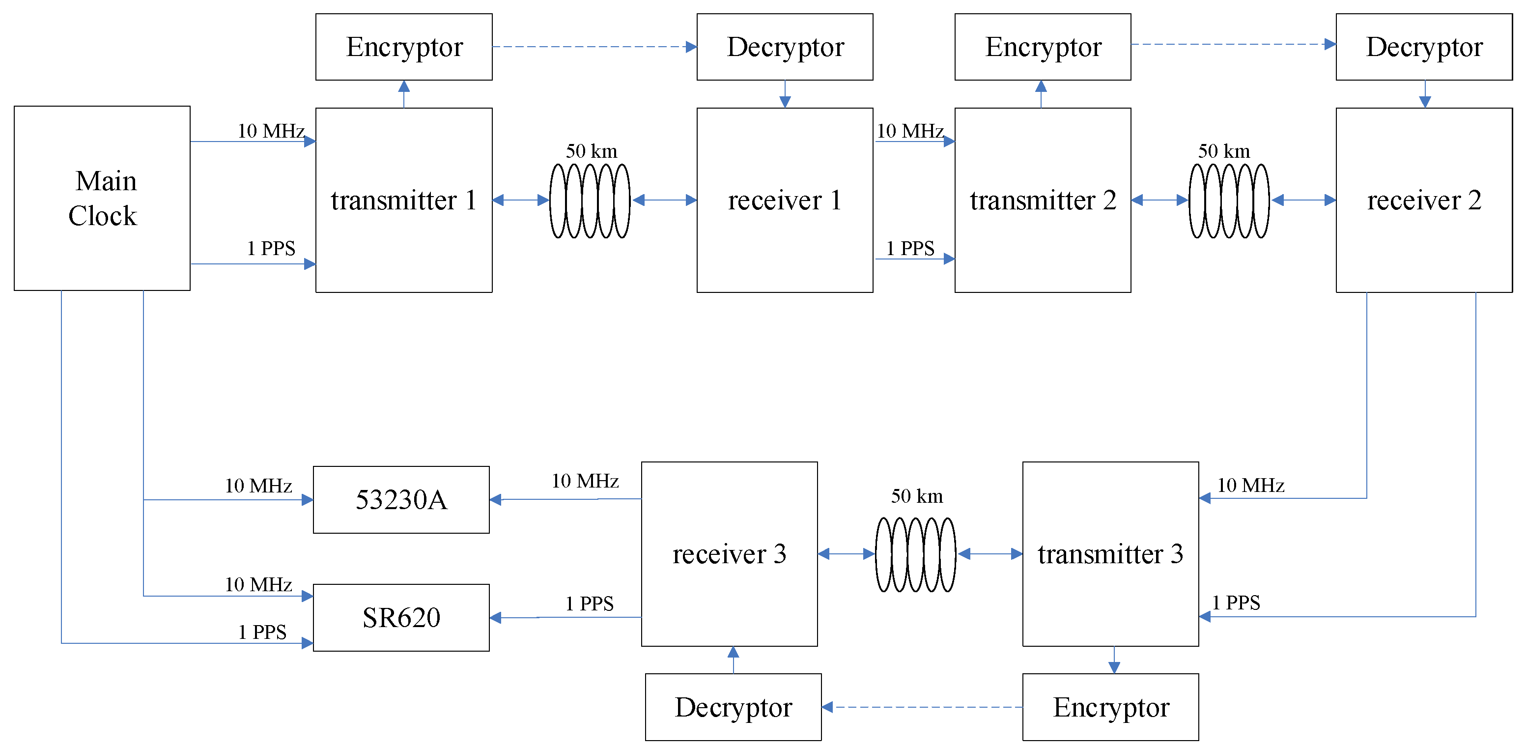
There are various ways to connect the links of an optical fiber time transfer system. Dense wavelength division multiplexing (DWDM) technology is widely used in most of the existing schemes. The advantage of this technology is that it can reduce the total number of required optical fibers and save optical fiber resources under a given information transmission capacity. For the long-distance optical fiber time synchronization system, the cascaded mode can also be used. The advantage of cascading is that the noise of the optical fiber link is not accumulated. The cascade receiver of the remote site can take out the time synchronization signal, which can be used directly by the next site of optical fiber time transfer local terminal equipment. The disadvantage is that the error introduced by the compensation mechanism in the cascade process will accumulate. Three nodes were chosen for this article. On the 150 km optical fiber link composed of three 50 km optical fibers, the secure optical fiber ring time service network was completed by using three encrypted secure time transfer devices.
According to the same encryption mode as a single device, a security encryption cascade test was carried out on the ring network. The optical fiber time transfer system encrypted the information of TIC at the first local site via the encryptor. After decryption at the first remote site, the receiver received the decrypted data from the external link and compared them with the data transmitted via the optical fiber. If the data were the same, the optical fiber time synchronization of the first cascade system was completed by using Formula (3). Finally, the time synchronization of the whole optical fiber cascaded system was completed by using three equipment units in the same way, as shown in Figure 8.
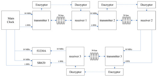
Figure 8.
A ring time transfer network via a 150 km fiber optic link with three nodes.
4.2. Result and Discussion
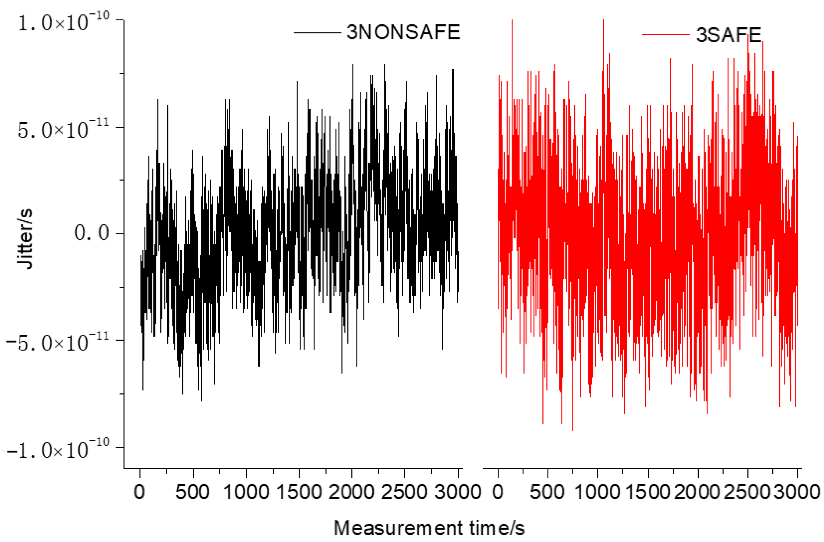
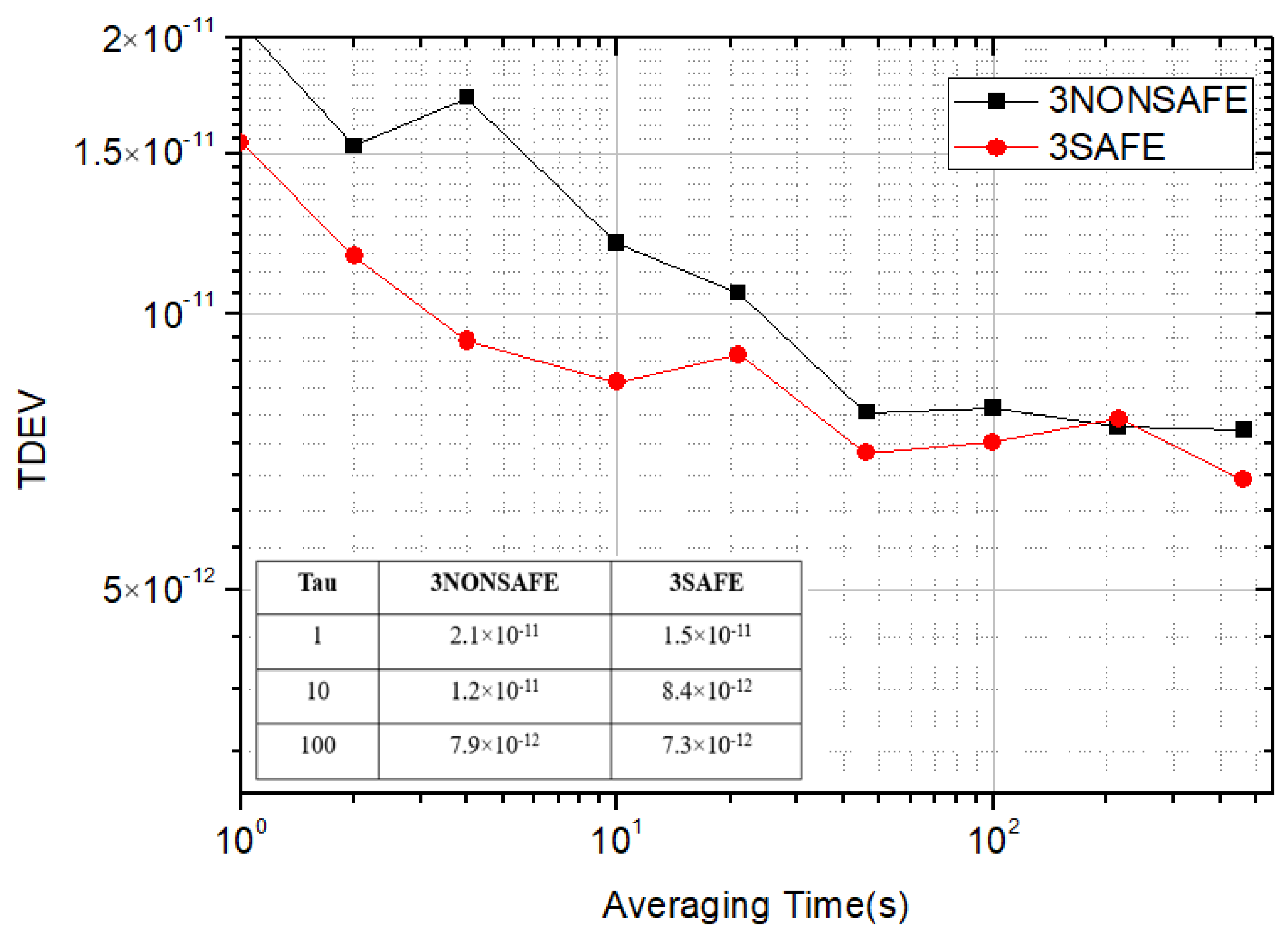
As shown in Figure 9 and Figure 10, the experimental analysis was carried out by sampling for 3000 s. Before the introduction of the security encryption scheme, the standard deviation of the time synchronization of the ring system composed of three devices was 2.6 × 10⁻¹¹, the peak-to-peak value of jitter was 157 ps, and the TDEV was 15.4 × 10⁻¹² at 1 s. With the introduction of the security encryption scheme, the measured standard deviation of time synchronization of the ring system was 3.1 × 10⁻¹¹, the peak-to-peak value of jitter was 193 ps, and the TDEV was 2.1 × 10⁻¹¹ at 1 s. After the security encryption scheme was introduced into the ring system composed of three cascaded devices, there was no significant difference in stability while ensuring the security of the system.

Figure 9.
Comparison of jitter using three safe and non-safe equipment.
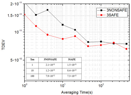
Figure 10.
Comparison of TDEV using three devices.
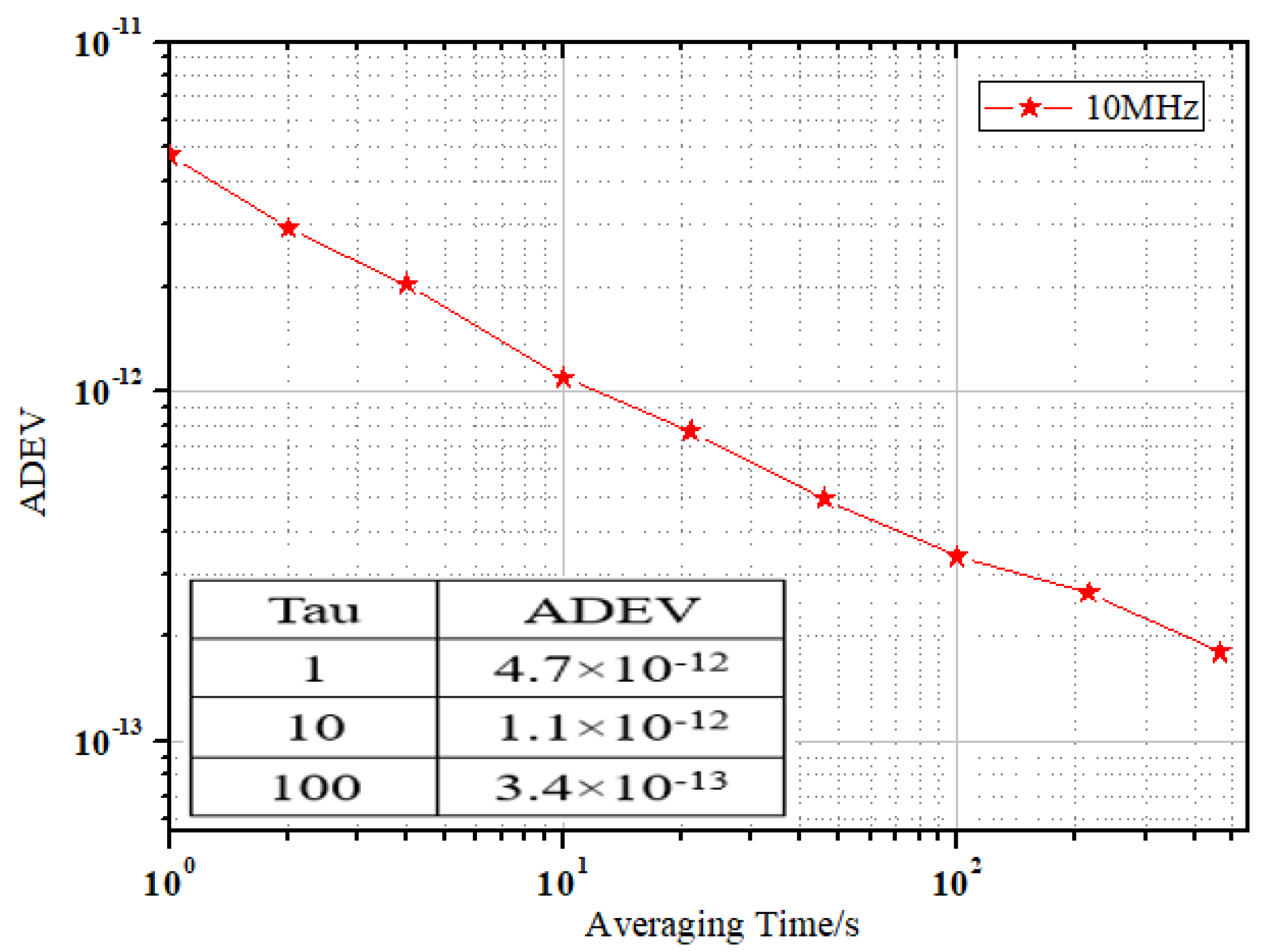
As shown in Figure 11, the 10 MHz frequency stability transferred by a single device and multiple devices in cascade was the same. As the analog phase-locked loop was used in the development of the equipment, the stability of the cascade equipment was not affected by the change in the program and the improvement of the encryption algorithm.
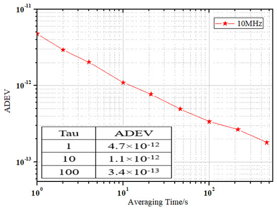
Figure 11.
Diagram of ADEV in 10 MHz.
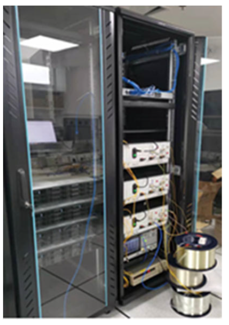
Figure 12 shows the physical connection diagram of the three devices for a ring network cascade test. In this experiment, the physical test of one, two, and three cascades was completed before and after adding the security encryption function. The stability of TDEV was tested on a 150 km optical fiber link composed of three 50 km, as shown in Table 3. The TDEV increased by about 1/ when the N time transfer devices were cascaded. With the increase in cascaded devices and fiber link length, the change in the signal-to-noise ratio (SNR) would lead to the deterioration of the TDEV of the system.
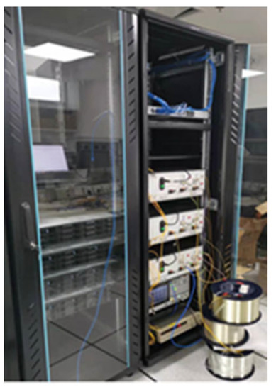
Figure 12.
Cascade experiment of ring network using three equipment.
Table 3.
Comparison of TDEV at 1 s averaging time with cascade equipment.
The reason for the deterioration of the encrypted device compared with the unencrypted device may be the introduction of the SM2 security encryption algorithm, as the data lengths of ciphertext and plaintext were inconsistent. In addition, there were time delays in the process of data serial-to-parallel conversion in encryption and decryption functions and transfer. Many factors together caused the accuracy of a single security timing device to decline. However, the overall indicators did not significantly deteriorate.
5. Conclusions
After the encryption function was introduced into the self-developed secure optical fiber time transfer equipment, it had little impact on the stability of the system. Additionally, the stability of the optical fiber time transfer system is still higher than GNSS and other systems. The secure high-precision optical fiber time transfer method in this paper strengthens the security protection of time information, which is a very necessary and promising line of research.
The next step is to carry out a secure and high-precision optical fiber time transfer network experiment on the field optical fiber link. The system will be optimized in terms of the TIC unit to improve the time transfer accuracy. Furthermore, the DWDM scheme will replace the cascade mode for experimental verification. Last but not least, we will explore a more secure quantum encryption mechanism to enhance the construction of a secure optical fiber time transfer network, which can further strengthen the security of the time service system.
Author Contributions
Conceptualization, X.G.; formal analysis, W.K.; Investigation, B.L.; project administration, T.L. and R.D.; resources, S.Z.; software, X.G.; supervision, T.L.; validation, Y.Q.; writing—original draft, X.G.; writing—review & editing, X.G. and T.L. All authors have read and agreed to the published version of the manuscript.
Funding
This research was funded by the National Natural Science Foundation of China (Grant Nos. 12033007, 61875205, 91836301, 12103058, and 61801458) and the Key Research and Development Plan of Guangdong Province (Grant No. 2018B030325001).
Institutional Review Board Statement
Not applicable.
Informed Consent Statement
Informed consent was obtained from all subjects involved in the study.
Data Availability Statement
The C programs and case analysis data used to support the findings of this study are available from the corresponding author upon request.
Conflicts of Interest
The authors declare no conflict of interest.
References
- Campbell, S.L.; Hutson, R.B.; Marti, G.E.; Goban, A.; Oppong, N.D.; McNally, R.L.; Sonderhouse, L.; Robinson, J.M.; Zhang, W.; Bloom, B.J.; et al. A Fermi-degenerate three-dimensional optical lattice clock. Science 2017, 358, 90–94. [Google Scholar] [CrossRef] [PubMed] [Green Version]
- Takano, T.; Takamoto, M.; Ushijima, I.; Ohmae, N.; Akatsuka, T.; Yamaguchi, A.; Kuroishi, Y.; Munekane, H.; Miyahara, Y.K.H.M.B.; Katori, H. Geopotential measurements with synchronously linked optical lattice clocks. Nat. Photonics 2016, 10, 662–666. [Google Scholar] [CrossRef]
- Kolkowitz, S.; Pikovski, I.; Langellier, N.; Lukin, M.D.; Walsworth, R.L.; Ye, J. Gravitational wave detection with optical lattice atomic clocks. Phys. Rev. D 2016, 94, 124043. [Google Scholar] [CrossRef] [Green Version]
- McGrew, W.F.; Zhang, X.; Fasano, R.J.; Schäffer, S.A.; Beloy, K.; Nicolodi, D.; Brown, R.; Hinkley, N.; Milani, G.; Schioppo, M.; et al. Atomic clock performance enabling geodesy below the centimetre level. Nature 2018, 564, 87–90. [Google Scholar] [CrossRef] [PubMed] [Green Version]
- Krehlik, P.; Sliwczyński, L.; Buczek, L.; KolOdziej, J.; Lipiński, M. Ultrastable long-distance fibre-optic time transfer: Active compensation over a wide range of delays. Metrologia 2015, 52, 82–88. [Google Scholar] [CrossRef]
- Śliwczyński, Ł.; Krehlik, P.; Czubla, A.; Buczek, Ł.; Lipinski, M. Dissemination of time and RF frequency via a stabilized fibre optic link over a distance of 420 km. Metrologia 2013, 50, 133. [Google Scholar] [CrossRef]
- Ebenhag, S.C.; Jaldehag, K.; Jarlemark, P.; Hedekvist, P.O.; Emardson, R.; Löthberg, P. Time transfer using an asynchronous computer network: Results from a 500 km baseline experiment. In Proceedings of the 39th Annual Precise Time and Time Interval Meeting, Long Beach, CA, USA, 27–29 November 2007; Volume 11, pp. 27–29. [Google Scholar]
- Zhang, H.; Dong, S.W.; Yuan, H.B.; Wu, W.J. Analysis of the performance of SDR TWSTFT. J. Time Freq. 2007, 42, 284. [Google Scholar]
- Wang, B.; Gao, C.; Chen, W.L.; Miao, J.; Wang, L.J. Precise and continuous time and frequency synchronisation at the 5×10⁻¹⁹ accuracy level. Sci. Rep. 2012, 2, 556. [Google Scholar] [CrossRef]
- Chen, F.X.; Zhao, K.; Zhou, X.; Liu, T.; Zhang, S.G. High-precision long-haul fiber-optic time transfer between multi stations. Chin. J. Phys. 2017, 66, 33–41. [Google Scholar]
- Liu, J.; Deng, X.; Zhang, X.; Zang, Q.; Wang, D.; Jiao, D.D.; Gao, J.; Wang, D.; Zhou, Q.; Liu, T.; et al. Progress of fiber-based optical frequency transfer in NTSC. J. Time Freq. 2021, 4, 231–243. [Google Scholar]
- Ebenhag, S.C.; Hedekvist, P.O.; Jarlemark, P.; Emardson, R.; Jaldehag, K.; Rieck, C.; Löthberg, P. Measurements and error sources in time transfer using asynchronous fiber network. IEEE Trans. Instrum. Meas. 2010, 59, 1918–1924. [Google Scholar] [CrossRef]
- Cui, L.; Yuan, M.; Li, Z.; He, J. Implementation of fault-tolerance WSN time synchronization algorithm for coal mine. J. PLA Univ. Sci. Technol. 2015, 23, 284–292. [Google Scholar]
- Olivier, L.; Amale, K.; Paul, E.P.; Daniele, R.; Joseph, A.; Christian, C.; Anne, A.K.; Giorigo, S. Simultaneous remote transfer of accurate timing and optical frequency over a public fiber network. Appl. Phys. B 2013, 110, 3–6. [Google Scholar]
- Gao, C.; Wang, B.; Bai, Y.; Miao, J.; Zhu, J.; Zhu, X.; Li, T.C.; Wang, L.J. Fiber Based Time and Frequency Synchronization System. Sci. Technol. Herald 2014, 32, 41–46. [Google Scholar]
- Chen, F.X.; Zhao, K.; Li, B.; Liu, B.; Guo, X.X.; Kong, W.C.; Chen, G.C.; Guo, B.L.; Liu, T.; Zhang, S.G. High-precision dual-wavelength Time Transfer via a 1085 km telecommunication fiber link. Chin. J. Phys. 2021, 70, 69–78. [Google Scholar]
- Chen, Z.F.; Zuo, F.X.; Hu, L.; Jin, Y.; Chen, J.P.; Wu, G.L. Time Synchronization System Based on Bidirectional Time-Division Multiplexing Transmission over Single Fiber with Same Wavelength. Chin. J. Lasers 2021, 48, 6. [Google Scholar]
- Qi, Z.; Quan, H.; Zhao, K.; Zhang, X.; Xue, W.; Chen, F.; Zhao, W.; Liu, T.; Dong, R.; Zhang, S. High-precision time-frequency signal simultaneous transfer system via a wdm-based fiber link. Photonics 2021, 8, 325. [Google Scholar]
- Wu, G.L.; Chen, J.P. Ultra-long haul high-precison fiber-optic two way time transfer. Sci. Technol. Herald 2016, 34, 99. [Google Scholar]
- Chen, D.; Xu, J.N.; Li, Z.Z.; Jiang, S.; He, H.Y.; Liang, Y.F. Advancement in Time Synchronization Technology Using Bi-Contrast Methods in Optical Fiber. Laser Optoelectron. Prog. 2020, 57, 9. [Google Scholar]
- Wang, T.F.; Zhang, H.F.; Xu, S. Security analysis and countermeasures for software implementation of SM2 algorithm. Appl. Res. Comput. 2021, 38, 2811–2815. [Google Scholar]
- Huang, H.; Wu, G.; Hu, L.; Chen, J. Influence of temperature on the precision of bidirectional TDM based fiber-optic time transfer. Acta Opt. Sin. 2015, 35, 105–111. [Google Scholar] [CrossRef]

Publisher’s Note: MDPI stays neutral with regard to jurisdictional claims in published maps and institutional affiliations. |
© 2022 by the authors. Licensee MDPI, Basel, Switzerland. This article is an open access article distributed under the terms and conditions of the Creative Commons Attribution (CC BY) license (https://creativecommons.org/licenses/by/4.0/).