Article

Problem-Oriented Modelling for Biomedical Engineering Systems

1
Institute of Civil Engineering, Warsaw University of Life Sciences—SGGW, 166 Nowoursynowska St., 02-787 Warsaw, Poland
2
Department of Transport Technologies, Lviv Polytechnic National University, 12 Stepana Bandery St., 79000 Lviv, Ukraine
3
Department of Mechanical and Energy, Lviv National Agrarian University, 1 Volodymyra Velykoho St., 30831 Dubliany, Ukraine
4
Department of Mechanical, Mykolayiv National Agrarian University, 17 Ukraine Krylova St., 54040 Mykolayiv, Ukraine
5
Institute of Environmental Engineering, Warsaw University of Life Sciences—SGGW, Nowoursynowska 159 St., 02-776 Warsaw, Poland
6
SGGW Water Centre, Warsaw University of Life Sciences—SGGW, 166 Nowoursynowska St., 02-787 Warsaw, Poland
*
Author to whom correspondence should be addressed.
Appl. Sci. 2022, 12(15), 7466; https://doi.org/10.3390/app12157466
Submission received: 15 June 2022 / Revised: 21 July 2022 / Accepted: 22 July 2022 / Published: 25 July 2022

Abstract

:
Technical system (TS) models are widely used for setting and solving problems for the improvement of biomedical engineering systems beyond simple parameter optimisation. They mostly focus on system elements, the change or replacement of which can provide significant technical and economic benefits. The natures of TS models and their methods of construction vary, but they all share several common features: a functional approach, a focus on the conflicting demands put on the particular elements of a system or their interactions, and the construction of models that assume the significance of those conflicts. Thus, modelling aims to visualise conflicts in a way that facilitates the setting and solving of tasks that lead to their elimination. Such modelling can be termed problem-oriented. Results of the analysis of problem-oriented models proposed by different authors have shown that they model the structure of problem functions or the structure of the TS fragments responsible for such functions. A graphic representation of these models allows for the comparison and identification of opportunities for further development and aggregation. In this paper, the joint application of several known and proposed models is suggested for efficient forecasting of biomedical engineering systems and their modernisation.

1. Introduction

The most common method used by engineers to solve problems is the trial-and-error method; unfortunately, this method often proves to be ineffective. The engineer’s problem is a task that cannot be solved by traditional methods and techniques. The science of inventive creation is understood as a methodology of searching for creative solutions for defined problems by stimulating and supporting creative thinking in various fields, allowing for the discovery of the most effective method or the best solution for a given creative problem. The effectiveness of this method results from a multifaceted planned search for a solution, directing the thinking process while increasing the probability of finding a highly qualitative solution. Determining the ideal end result allows for the elimination of the disadvantages of the actual technical system and the preservation of its advantages. The process avoids the creation of new complications or the introduction of new disadvantages. All these features are especially important if the technical system is related to the safety and lives of animals or people. The most commonly used methods for creative problem solving are well-established, such as: brainstorming [1] with different variants, the Delphi method [2], morphological analysis [3] or synectics [4], but also more modern methods such as: QAM or QC-story [5] or 8D methodology [6]. Numerous publications that present practical applications in various fields draw attention to the constantly modified and improved theory of inventive problem solving (TRIZ) by Altshuller. The results of TRIZ method implementations prove it to be highly effective for solving technical [7,8], organizational [9] and social [10,11] problems.
The combined trimming method (a tool for problem analysis and solving by TRIZ) and bio-inspired designing (BID) was used in [12], where the feasibility and effectiveness of the proposed method was verified by redesigning a steel tape armoring machine. Another example of combining TRIZ tools with other inventive problem solving methods is presented in [13], where the application of the combined use of TRIZ and Eco-compass to present a performance increase in certain environmental parameters, thus promoting sustainable innovation. This method could be helpful in solving the problems described in [14,15,16,17].
The range of problem-solving methods is relatively wide and many of them can be universal, so there is no strict division of methods according to their application in technology.
Regarding human safety and life, application of the TRIZ method in the conceptual design of walking crutches is presented in [18]. In [19], the design process of an ankle orthosis system using the tools of the Invention Problem Solving Theory is described. The design of an interventional surgery robot based on the TRIZ theory was presented in [20]. TRIZ was also used in the development of an exoskeleton for sarcopenia to assist elderly people who require assistance in performing daily activities [21]. TRIZ has also been helpful in developing an effective external defibrillator solution for patients at risk of sudden cardiac arrest (SCA), in whom invasive internal defibrillator implantation surgery is not possible [22]. An analysis of the frequency and methods by which TRIZ has been used to develop creative solutions to healthcare sector problems, along with the evidence of its effectiveness in practice, is described in [23,24,25].
In general, biomedical engineering systems (BMS) can be understood as technical systems (TS) based on advances in technical science and technology for the practical solution of medical and veterinary problems. The human-centred nature of BMS projects makes them more difficult to construct, yet easier to implement. On one hand, this facilitates the attraction of investors and promotes cooperation during the research and development phases. On the other hand, because human beings are integral parts of BMS design objects, the level of complexity of the design tasks is extremely high and naturally increases in the course of BMS development. As the complexity of of a specific project’s tasks to be solved increases, and the time for development decreases, the need for an effective unified apparatus for setting and solving problems concerning the improvement and development of new BMS systems becomes increasingly evident. This seems impossible without the development of specialised models and procedures for modelling such systems and their subsequent problems. The methods for constructing these models and the natures of the models themselves vary, but they all share several common features: a functional approach, a focus on the conflicting demands put on the particular elements of a system or their interactions, and the construction of models that assume the significance of those conflicts. Thus, modelling aims to visualise conflicts in a way that facilitates the setting and solving of tasks that lead to their elimination. Such modelling is termed conflict- or problem-oriented, and the models developed under this approach prove to be problem-oriented models. Results of the analysis of problem-oriented models proposed by different authors have shown that these models appear to model the structure of problem functions or the structure of fragments of TS responsible for such functions. A graphic representation of these models allows for their comparison, and can help identify opportunities for further development and aggregation. As a result, new modifications of these models have been developed. The joint application of several known and proposed models is suggested for efficient bioengineering system forecast and modernization, because the creation of competitive bioengineering systems (BMS) is impossible without effective methods of setting and solving the structural synthesis problems of such systems. The effectiveness of these methods, the degree of their algorithmizing, and their suitability for automation directly depend on the availability and correctness of technical system (TS) structural synthesis models.
To set and solve the problems of TS improvement beyond parameter optimization, different TS models or their fragments are widely used. As a result, it is possible to focus on the characteristics or elements of the system, the change or replacement of which can provide significant technical and economic benefits. The methods for constructing these models and the natures of the models themselves vary, but all the models have several common features:
  • Their development is based on a functional approach, in which each structural element of the system is chiefly treated as a carrier or an object with a certain function (action).
  • Every function is defined in terms of its carrier (which creates the action), its object (to which the carrier’s action is directed), the action itself, and the conditions of the action’s realization.
  • In general, the system structure is represented by a function tree (tree function graph—TFG), the branches of which are actions, and the nodes being their carriers and objects.
  • Functions, the realisation of which does not provide the required quality parameters of the system, are called problem functions.
  • It is assumed that the imperfection and interrelation of individual interactions within the TFG results in conflicting requirements for particular TFG branches and nodes, the assuring of which needs either the finding of the optimal trade-off between certain parameters or a reconfiguration of the graph.
  • Functions, the realisation of which should meet contradictory demands to system parameters, elements, or their interactions, are called conflicting, and the conflicts (contradictions) of demands themselves are considered to be the main source of improvement and development of TS when exhausting the optimization potential.
  • TS and task models are built considering the significance of these conflicts. Since the purpose of modelling is directly related to the identification and solving of conflict problems or situations, it is appropriate to classify models with the above features into a separate category of problem-oriented models (Table 1).
As is evident from Table 1, problem-oriented models appear to be models of the structure of problem functions or the structure of fragments of TS associated with these functions. Although almost all of these models are claimed by their authors as absolutely original, we consider them all to be developments of elementary models of problem functions in one direction or another.
Analysis of the dynamics of model emergence suggests that problem-oriented modelling develops in the following directions:
  • Introducing additional elements into the model for expanding the field of search.
  • Eefining the axiomatics of the model, i.e., the essential elements and the relationships between them and their representations, in order to clarify the search directions.
  • Aggregation of different types of models in order to combine their advantages.
  • Combination of models and problem-solving tools.
The aim of this study is to analyse the existing models for setting and solving heuristic structural synthesis problems and to identify opportunities for the universalisation and specialisation of particular models by aggregating current research results.
In order to compare these models and identify opportunities for further aggregation, we applied a graphic representation of the models using isomorphic transformations to maximise the visibility of common elements and parts of the graphs.

2. Background

2.1. Substance-Field Model (SF)

The substance-field model (SF) is a model in the form of a minimal workable technical system consisting of two substance elements (S1—tool, function carrier and S2—function object) and their mutual interactions, specified to the physical nature of a corresponding field (F) [26,27,28,37]. The method for modelling the system or its parts as a single SF or an SF network is called SF analysis (SFA).
A graphic presentation of the model is a triangle with vertices corresponding to the model components (S1, S2, and F) and edges representing the links between the components (Figure 1). The graphic symbols (different types of arrows), which represent interactions between the different components of an SF model, are shown in Table 2.
From the perspective of the problem-oriented approach, the actual object of SF modelling is the problem function or functions. In fact, the model is a graphic representation of an unsatisfactory interaction between two elements, or a set of interactions between them, with at least one of them being undesirable. The following functions may be considered to be problem functions: a missing useful function; a harmful (undesirable) function, the occurrence of which accompanies the effective realisation of a useful function under given conditions; and an ineffective useful function, whose realisation quality indicators cannot be improved under the existing conditions within the limits of a known technical solution. SFA provides rules for problem setting and solving, which present ways of transforming the generic SFs into useful effective SFs by adding new elements or eliminating existing elements [26,27,28]. These rules are organised and specified according to the generic SF form and the terms of useful function realisation in a system of standards for engineering problem solving [26,28,29,31,38].

2.2. Physical Contradiction (PhC)

The PhC model [27,28,31] reflects the situation that emerges when a certain attribute of a material object must have two different values at the same time to provide a required result. The attribute can be a physical parameter, aggregate state, location, etc. This is a structural model of a conflict problem in the form of a more or less formalised description of incompatible requirements to the value of a certain property of a certain element (problem): an element must have a certain value of a property (state A) to satisfy one quality criterion (to perform one necessary useful function) and not have it (state A) to satisfy another criterion (to perform another necessary useful function or to ensure that a harmful one does not occur). The problem property can be defined as a parameter, aggregate state, location description, etc. Such a model a priori contains conflicting functions, a problem element, involved in both conflicting functions, and inconsistent requirements for the parameter of that element to be met in order to realise the conflicting functions. In such modelling, the problem-solving tool is the technique of eliminating physical and technical contradictions.
Since SF is the graphic representation of a problem function, i.e., of the conflicting function, which has been assumed to be undesirable, each model in the form of a physical contradiction can be associated with at least one SF model. The substance-field model in fact corresponds to the PhC ‘half’ that contains an undesirable function: the performance of a useful function in state A is accompanied by the occurrence of an undesirable action on the object of the useful function or its instrument (combined harmful SF) or on a third element (harmful SF). In the case of state A, there are no harmful effects, but the useful action is not implemented at all or is poorly implemented (ineffective SF). Analysis of the variations of SF models given in 76 standards for technical problem solving [38] allowed for the confirmation of this correspondence [42] for cases in which the composition of the substance participants of conflicting functions were identical.

2.3. Function Model (FM) and Functional Analysis Diagram (FA)

The FM is a model reflecting the structure of functional relationships (i.e., functions, actions) between the components of the System and its Super system [31]. Functions are characterised by: category (useful, harmful, neutral), quality of performance (insufficient, excessive), cost level (insignificant, acceptable and unacceptable), and cost of corresponding components. The graphic representation of FM is the FA diagram (Functional Analysis Diagram).
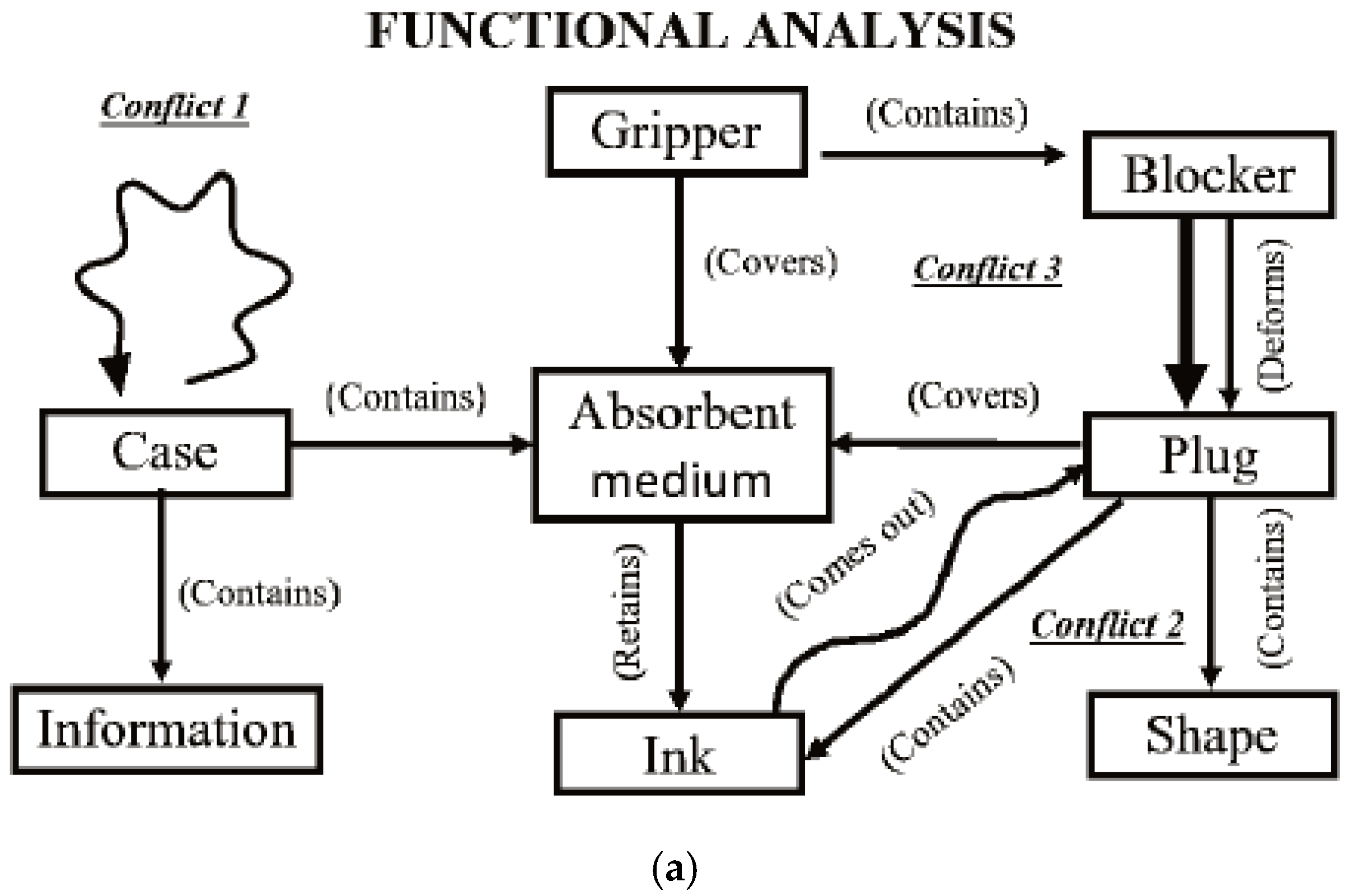
The FA Diagram is an oriented graph with vertices corresponding to system components and edges reflecting their mutual interactions [31,32]. Arrows point to the action direction. In some versions of the model, the edge pattern reflects the action character (useful or harmful) and the level of performance (sufficient, insufficient, excessive) in the notation of the Substance-Field Analysis (Table 2). Use of the SFA notation allows for the visualization of the existing conflicts, the combination of the modelling process with the problem setting process, the selection of a potential tool for solving the problem, and the solving of the problem by applying the SFA or PhC/TC tools. The function rank (index), value and cost can be specified for the purpose of VE (value engineering).

2.4. ‘Nested’ Function Model and Extended ‘Nested’ Function Model

The ‘Nested’ Function Model and the Extended ‘Nested’ Function Model [30] are representations of the functional model within a multiscreen approach. As every system is a part of a super system and itself consists of subsystems, which are composed of lower-level subsystems, etc., the Function Models can be built on different levels and linked throughout the ‘system tree’. This enables a detailed analysis of complex systems, starting from a high System-level and going down to an arbitrarily detailed Sub-Sub-(…)-System level.
The level at which function models are built determines the level of problem solution (disruptive or incremental), and the range and scope of changes within the system and its environment. Modelling higher-level interactions in cases where the investigated product itself is only one of the many components, and where the product might be subject to trimming or other Super system changes, provides an opportunity to reformulate the main function of the system according to the consumer demands identified at a higher structural level. Thus, other problems can be identified and solved, and a more efficient result can be achieved.
The Extended ‘Nested’ Function Model expands the ‘Nested’ Function Model by using the time axis of the multiscreen approach. Constructing the Function Model of previous (past) versions of the System with the respective Sub- and Super-systems allows for assess to the methods by which the system evolved in the past, making the identification of applicable Trends of Engineering Systems evolution possible. Applying these trends enables the forecasting of the probable future state (functional model) of the system with the best MPV and the identification of not only current, but also upcoming conflicts.
To conclude, all variants of functional models and the multiscreen model are tools for setting conflict problems, and are compatible with the optimisation and heuristic methods for solving them.

2.5. Causal Loop Diagram (CLD)

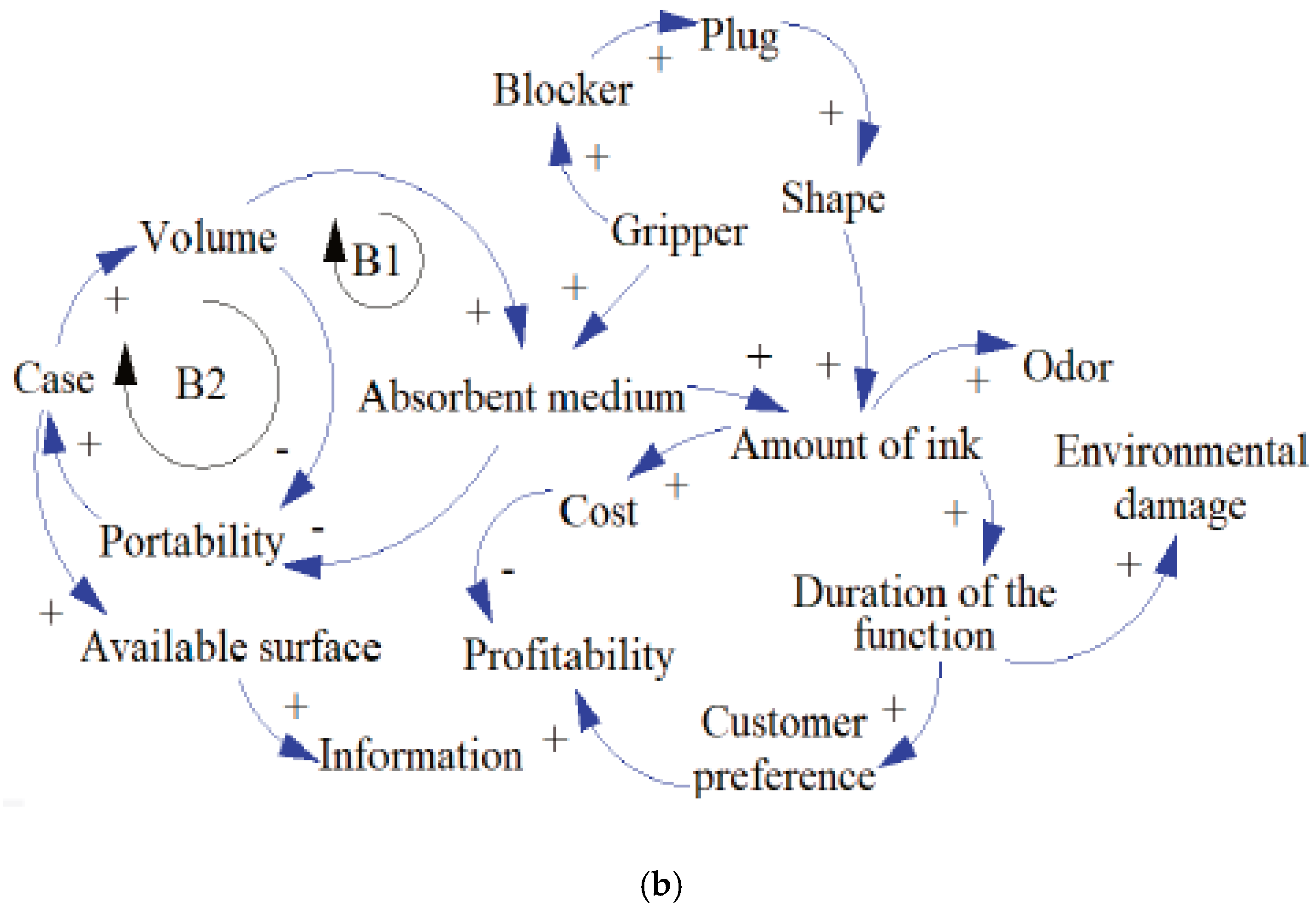
The Causal Loop Diagram (CLD) [32] in its simplest form is also an oriented graph, but, unlike FAD, the vertices of the graph represent not only the interacting components of the system, but also its main quality parameters and the function parameters providing these parameters. Thus, the edges reflect both the interactions of the components, and the impact of the components and the function parameters on the quality parameters. An edge arrow represents the causal link between the variables (component or parameter) that it connects. A link has a polarity, which denotes the type of influence, either positive or negative (Figure 2b).
The use of signs in a relation gives the possibility for identifying existing problems and provides an opportunity to outline ways of solving the problem (to create problem solving paths). Variables are classified as those that change over time and those that remain constant throughout the model. Identification of the polarities reveals the cohesion of variables. Once the variables are related, it is possible to identify the feedback (positive) and balancing (negative) loops that are in charge of appropriate feeding and stabilising of the system. Common and different features of FA and CLD can be recognised in Figure 2.

2.6. Tool-Object-Product Model (TOP Model)

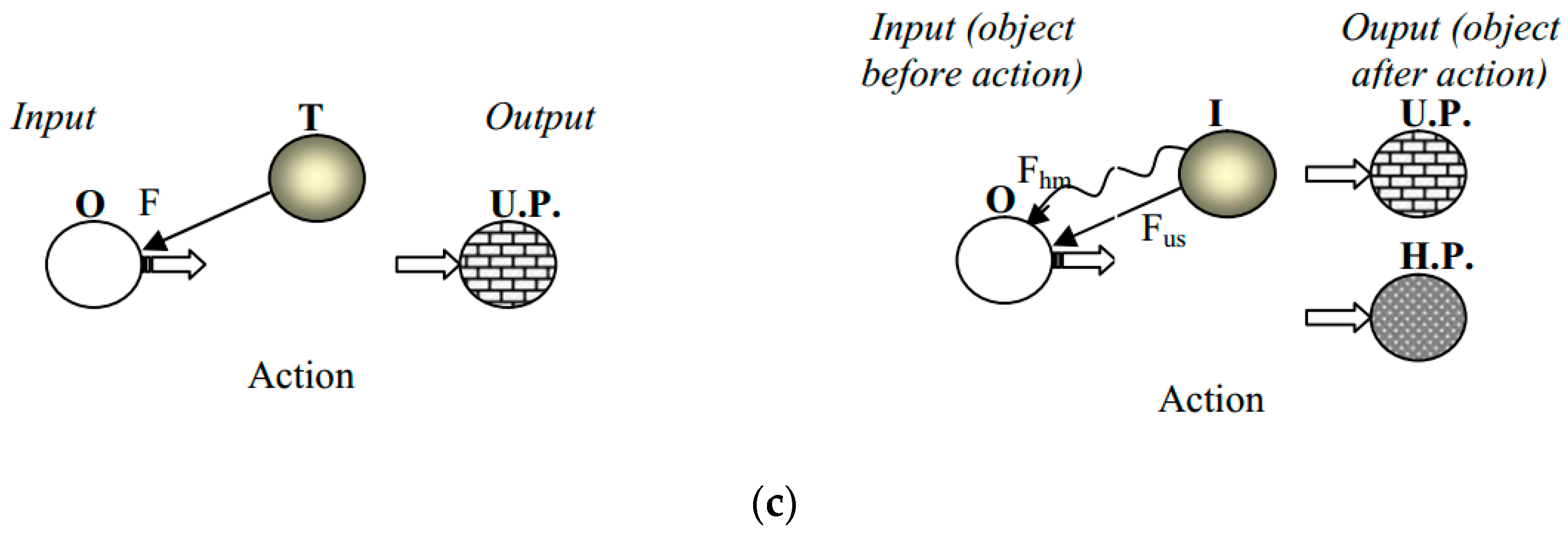
The Tool-Object-Product (TOP) [33,34] model is a graphic model of the problem shown as a combination of the action tool, action object, and action product in the form of a transformed action object. The useful action of tool T on object O realised via field (F) results in the transformation of object O into a useful product (U.P.). The action is denoted by an arrow, while the transformation is denoted by a double arrow (Figure 3a).
If a necessary useful action (Fus) that transforms object O into a useful product (U.P.) is accompanied by an undesirable impact (Fhm) on object O, thus producing a harmful product (H.P.) (Figure 3b) or a worsened level of another system function, one is faced with a conflict problem or problems to be solved.
An isomorphic graphic representation of the TOP model in a more traditional form for functional models is shown below (Figure 3c).
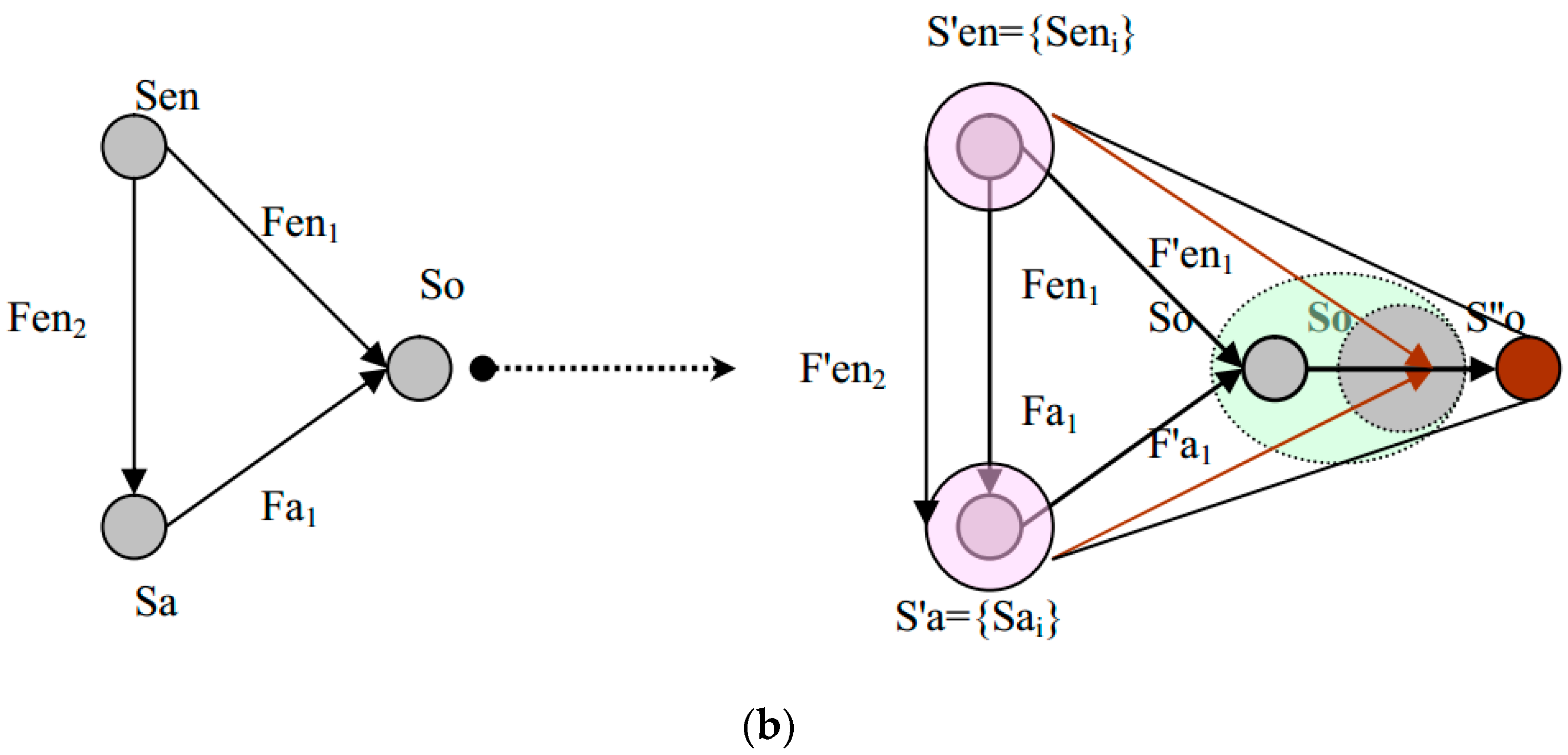
Comparison of Figure 1 and Figure 3c indicates that the TOP model is just an extension of the combined SF model including the results of useful and harmful interactions (Figure 4).
Figure 4 shows that the TOP model is a combined SF model, subdivided into two different SFs—a useful effective and a harmful one, with two additional elements—the results of useful and harmful interactions. Thus, the object of an action (product) is represented twice in the model—before it has been acted upon by the tool and after the action. The advantage of this representation is the extension of the solution search beyond the transformation of the tool-product interaction (for example, the search for ways to destroy the already formed harmful product); in turn, the disadvantage is the limitation caused by conflicts, in which both conflictive functions are realised by the same substance participants. Cases with, for example, different objects of useful and harmful functions, etc., are not considered. The construction of a coherent tree of TOP models of a TS part allows for the creation of an O2-A-R diagram (Object-Action-Object-Result-Diagram) [44] of the TS and for the identification of alternative problems, which, when solved, would provides the same useful result.

2.7. Triad Models

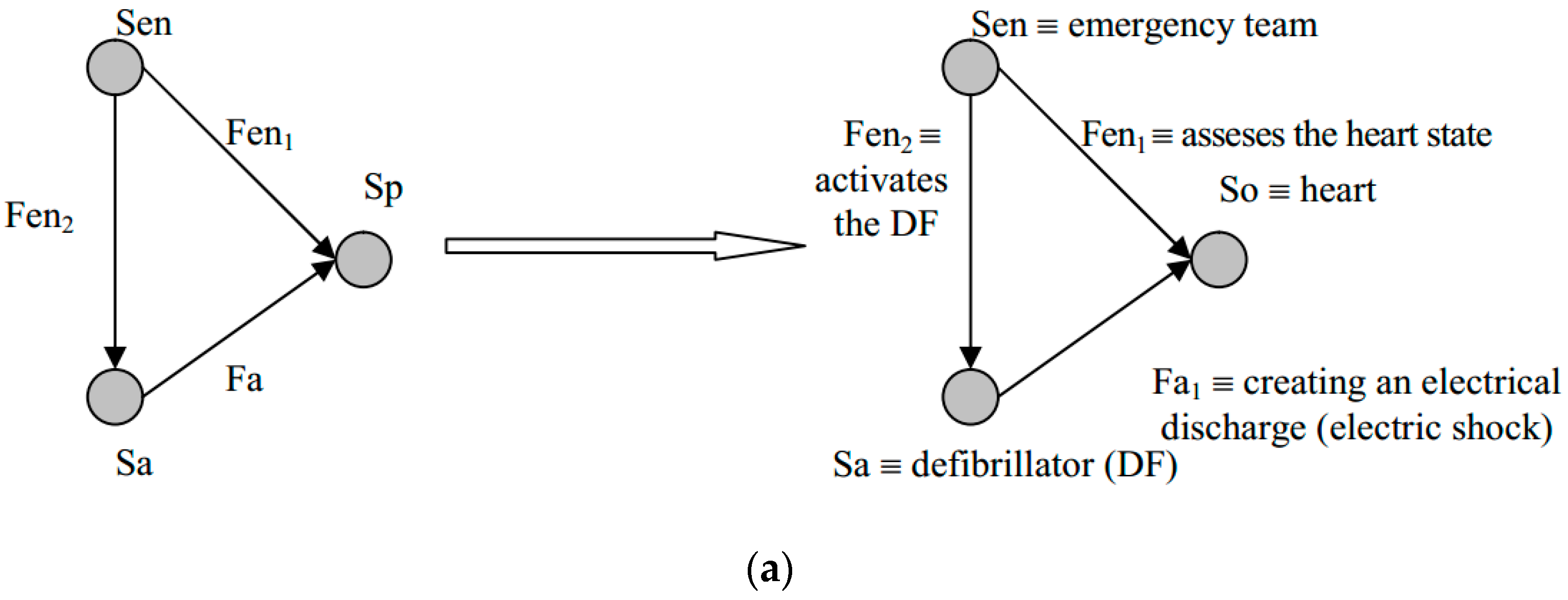
Triad models [35,45] are graphic representations of the interactions between three elements: a passive object (Sp≡S0, the object of the useful effect produced by the two other triad elements) and two active elements, one of which is the carrier of the main useful action (Sa, active object) that provides the main system function, and the other, the so called ‘enabling element’ (Sen, enabling object), which ensures that the useful action is performed in an appropriate way at an appropriate time. According to [35], removal of any of these elements from the system without rearranging the functional relationships makes the system non-viable. In triad modelling, the Triad + Pruning algorithm is a problem-setting and problem-solving tool [35,45].
An example of the triad model for the ‘defibrillator’ technical system is shown in Figure 5a.
Analysis of the proposed problem-oriented models and the effectiveness of their application suggests that the triad modelling method [35,42,45], which has been successfully applied for several years by the American firm BioFutures Incorporated, seems to be the most appropriate for setting and solving conflict problems of BMS design. As we have shown in [42], the triad model can be further improved by stepwise aggregation of two other problem-oriented models (the SF model and the TOP model) into the triad model, combined with the system transformation operator [42] and 9S operator [29,34]. Thus, any of the substantial elements of the triad are regarded as representatives of a certain class of objects, which allows for simultaneous consideration of two passive functions—the main and the basic, and for significant extension of the options of system improvement and development by morphological search of alternative triad elements within the boundaries of a certain class of objects. The model obtained as a result of imposing the system operator on the aggregated TOP Triad model contains two triads ‘nested’ into one another, therefore we have proposed to call it a ‘bi-triad model’ [42]. A variant of such model for defibrillator TS is presented below (Figure 5b).
The bi-triad representation of the TC allows for the expansion of the set of elements—candidates for removal in the ‘Triad + Pruning’ algorithm, and for the identification of new strategic directions for TC evolution.

3. Proposed Expanded Triad Model

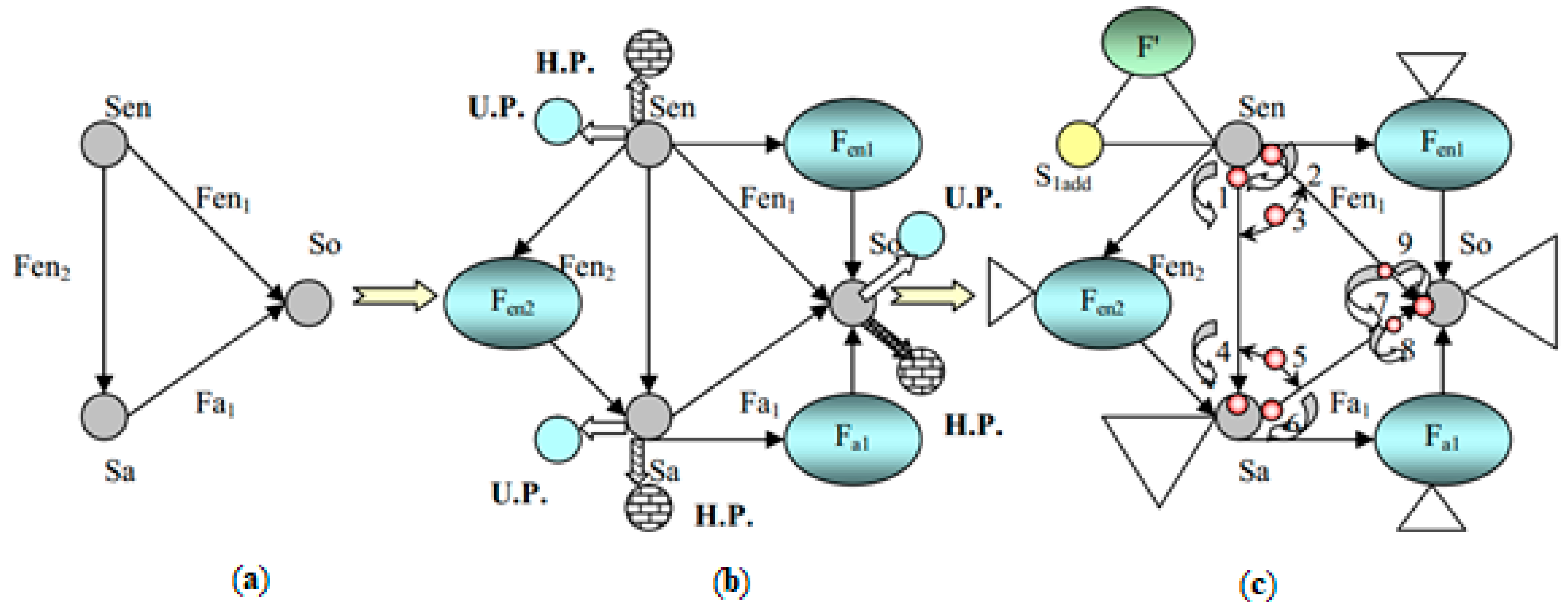
In the case of modernising an existing system, it seems more reasonable to expand the triad model (Figure 6a) into a set of related SF models (Figure 6b). Analysis of problem interactions within these models, with ranking by economic or medical–technical criteria, is likely to reveal the most urgent tasks for the improvement of the system under consideration. In triad models, as well as in TOP models, the field is not treated as an individual element (node) of the model, but is defined above the relationship between the substance elements. This is totally justified, since the ‘field’ is just a way of realising the relationship and its identification, as a particular element complicates the identification of the triad model as a set of three SFs. Subsequently, each of the identified elements of the SFs can be expanded into a new SF (Figure 6c), and so on.
Such representation of the triad model allows for the aggregation of all types of SF models, and for the integration of the SF analysis apparatus [27,28,31] and standards for engineering problem solving [26,28,29,38] into the ‘Triad + Pruning’ method.
Simultaneously, the most correct and universal model for considering an improvement of the TS by transformation of the prototype is provided by a physical contradiction (PhC) model. It is obvious that aggregating PhC models into triads would allow for the integration of problem-solving tools inherent in bi-triad modelling and PhC modelling (contradiction elimination techniques) into a single algorithm.
Analysis of the expanded triad model (Figure 6) shows that each of the real triad elements can be considered as a problem element, incompatible demands to which can be put forward by each pair of interactions in which the element participates. As can be seen from the analysis of these pairs of interactions, the enabling and active elements are actual or potential participants in three pairs of interactions (Figure 7):
  • The enabling element Sen can participate in the following pairs of interactions: ‘useful functions Fen1 and Fen2′; ‘useful function Fen1 and accompanying undesirable function Fnd1, which may be generated when attempting to improve Fen1′; ‘useful function Fen2 and accompanying undesirable function Fnd2, which may be generated when improving Fen1 via the enabling element.’
  • The active element Sa can participate in the following pairs of interactions: ‘useful function Fen2 (for which the active element is a product) and useful function Fa (for which the active element is a tool)’, ‘useful function Fa and accompanying undesirable function Fnd3, which may be generated when attempting to improve Fa’; ‘useful function Fen2 and accompanying undesirable function Fnd4, which may be generated when attempting to improve Fen2 by changing the active element.’
  • The passive element S0 can participate in the following pairs of interactions: ‘useful functions Fen1 and Fen2 (when considering the passive element as the problem one)’; ‘useful function Fa and accompanying undesirable function Fnd5, which may originate when attempting to improve Fa by affecting the passive element’; ‘useful function Fen1 and accompanying undesirable function Fnd6, which may originate when attempting to improve Fa by affecting the passive element’.
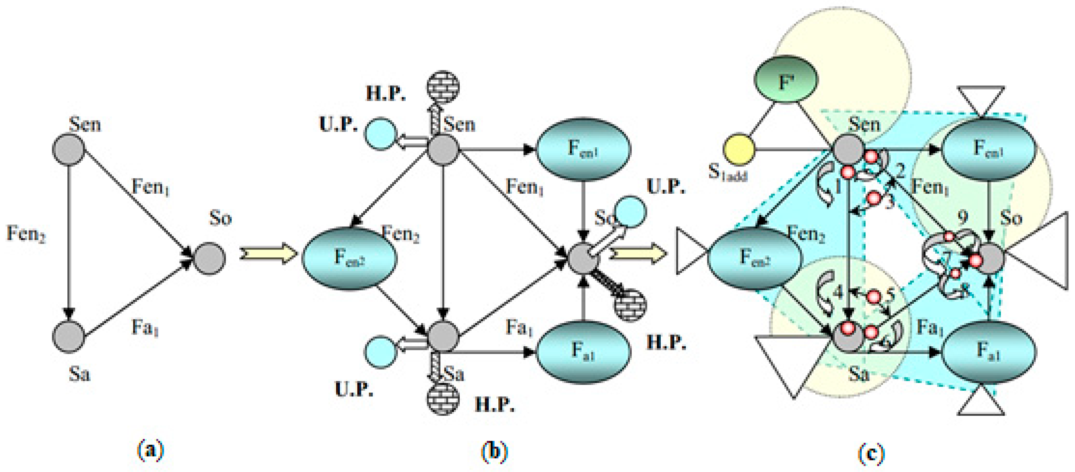
Obviously, physical contradictions 1–7 will raise the most interest. For each of them, an appropriate space–time model of conflict can be obtained, and problem-solving directions can be identified, involving both the technique of contradiction elimination and the technique of SF analysis (standards for problem solving). To aggregate the TOP models into this model, it is necessary to identify the products of useful and harmful interactions (U.P and H.P) for all triad vertices, as in Figure 7b above. In this case, since the ‘harmful product’ is the result of a number of identified interactions, we actually obtain not one, but several TOP models for each vertex.
As Figure 7 indicates, the triad model can be expanded into any of the mentioned types of models within the Triad elements, thereby making it possible to take the Triad as a basic model when setting the problems of TS improvement by transformational methods. For each of the nodal problems, a set of problem models in the form of appropriate PhCs can easily be obtained (Figure 8). When proceeding to a bi-triad model, the tasks of TS synthesis with complete substitution of elements can be proposed.

4. Application of the Model to Inventive Problem Solving in the Case of Defibrillator Improvement

A challenge associated with defibrillators is tissue burn due to the absorption of energy from the defibrillation electrical pulse. The results of clinical trials have shown that the shape and amplitude of the defibrillation pulse are to be strictly defined in order to increase the likelihood of reviving the patient. The area under the pulse amplitude-time curve gives the pulse energy, and a large dose of defibrillation energy causes the harmful side effects mentioned above.
The problem model as a physical contradiction may be formulated as follows: “the shape of the electrical pulse profile must be strictly fixed to increase the probability of reviving the patient, and the shape of the electrical pulse profile must be modified to reduce the area under the pulse-amplitude-time curve to cut the pulse energy and decrease the probability of burns”.
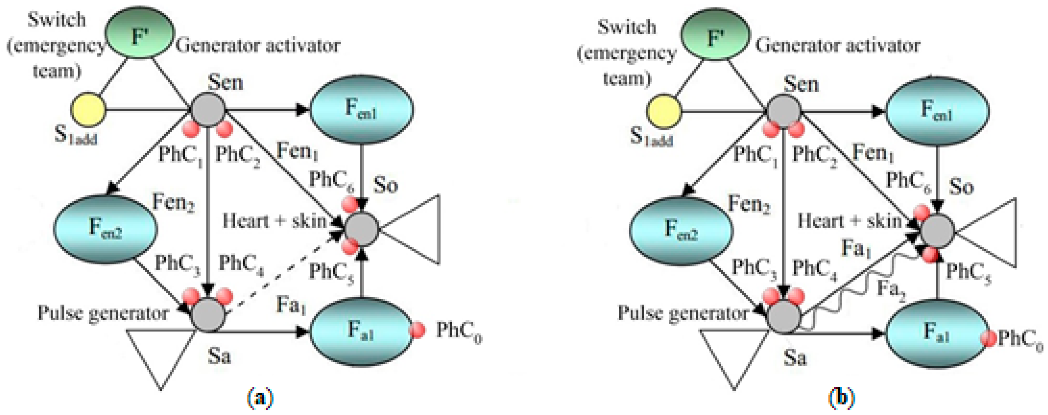
The expanded triad model for this problem is shown below (Figure 9).
The model is presented with two variants, (a) and (b), each corresponding to a half of the basic contradiction PhC0 (state A and state B). The physical contradictions associated with the elements of the triad will be the same for both states. The contradictions PhC0 ÷ PhC6 (Figure 9) seem to be the most promising regarding the elimination of the investigated problem. They are:
PhC0—Basic contradiction, regarding the requirements to pulse profile stability and energy level (Fa1) from the interactions between Sen and Sa.
PhC1—Contradiction, regarding the requirements to Sen (has to be switched/has to be not switched) from the interactions between Sen and Sa.
PhC2—Contradiction, regarding the requirements to Sen (has to ensure heart susceptibility to low energy pulse/has to ensure skin and heart immunity to thermal effects of the high energy pulse) from the interactions between Sen and S0.
PhC3—Regarding the requirements to Sa (has to produce a strictly fixed high energy pulse/has to produce low energy pulse) from the interactions between Sa and S0;
PhC4—regarding the requirements to Sa (has to be switched/has to be not switched) from the interactions between Sa and Sen.
PhC5—Regarding the requirements to S0 (has to change the contraction rhythm at a pulse energy below the threshold/can change the contraction rhythm only at a pulse energy above the threshold) from the interactions between Sa and S0.
PhC6—Regarding the requirements to S0 (has to respond to actuation without delay/is physically unable to do so) from the interactions between Sen and S0.
SF representations of the model elements appear to be different in states A and B. In state A, corresponding to the optional pulse profile and low pulse energy, there is an inefficient SF “Sa-Fa-S0”. In state B, corresponding to a strictly fixed pulse profile and high pulse energy, we have a combined useful and harmful SF.
As for the SF components of the model, the most obvious candidates for setting the problems for eliminating PhC0 are the SFs:
  • Inefficient SF “Sa-Fa-S0” (state A, Figure 9a).
  • Harmful SF “Sa-Fa2-S0” (state B, Figure 9b).
Secondly, we can consider the SFs “Sen-Fen2-Sa” and “Sen-Fen1-S0,” treating them as weakly controlled SFs, which do not provide enough control of the pulse generator mode and the heart condition in terms of the pulse responsiveness and burn resistance.
Modelling of these physical contradictions in time and space suggests the possibility for resolving them in time, space, and through systemic transitions by splitting them in time and space. As far as the SFs are concerned, increasing efficiency, eliminating harmful constituents, and improving controllability can be achieved by standard methods described in [27,28], i.e., by introducing additional substances and fields, deploying individual SF constituents, dynamising the impacts (fields), etc. [28,29]. Combining the SF model, the model in the form of PhC, and the micro triad model (in fact coinciding with the SF model) with a multi-screen approach, we can show that in valid directions (time, space, system transitions) of PhC elimination [27,28] and within changes of the three triad elements (electrode, pulse, heart), this contradiction can be solved in several ways, i.e.,:
  • By a systemic transition at the stage of the previous key problems [28]—changing the pulse shape requirements in such a way that a lower energy pulse would achieve the same defibrillation effect (transition to bipolar pulses of complex shape with an increased electrotherapeutic index—ratio of damaging and defibrillating thresholds).
  • By separating the conflicting requirements PhC0, PhC3 in time or space by sequential emission of multiple pulses (in time, US Patent 6 405 084 [46]) and/or simultaneously (multiple implantable electrodes at different parts of the heart, US Patent 6038472 [47]), each with the desired profile but a smaller amplitude, so that the total energy delivered equals the energy required for effective defibrillation (solution implemented in US Patents 5531768 [48], 5531764 [49]).
  • By separating conflicting requirements PhC0, PhC3 in time by “overshooting” [27,28,32], i.e., by speeding up the most dangerous parts of the process. US patent 6029085 [50] proposes a defibrillator circuit design with accelerated capacitor charging, which stabilises the defibrillation threshold and increases patient safety.
  • By separating conflicting requirements PhC5 over time with increase of the efficiency of the inefficient subfield “Sa-Fa-S0” by changing the absorption capacity of the heart (increasing the energy that is transferred to the heart is achieved by changing the parameters of the heart. US Patent 6363276 [51] provides a device consisting of a pump capable of pumping blood and a flow rate meter. The device can pump some of the blood out of the ventricle, resulting in ventricle volume decrease and a larger portion of the defibrillation pulse energy absorbed into the appropriate parts of the heart);
  • By separating conflicting requirements PhC0, PhC3 over time with destruction of a harmful SF “Sa-Fa2-S0” with excessive energy impact by absorbing excess discharge energy from storage capacitors (US patent 6212429 [52], according to which additional pulses of opposite polarity are emitted to suppress the excess energy impact).
  • By a systemic transition (fragmentation and transition to the micro level providing opposite properties to the system and its parts) with obtaining the required pulse profile in a ‘pulsating mode’ due to the emission of a sequence of extremely short and rapidly subsequent rectangular pulses of varying amplitude and polarity, the envelope of which sets the desired pulse shape and energy (US Patent 6173274 [53]).
  • By separating conflicting requirements PhC0, PhC2, PhC3 in time in combination with systemic transition by using a biphasic pulse delivery circuit with two capacitors, each delivering different phases of the biphasic pulse, where at least a portion of the charge on the second capacitor is provided by the current flow through the patient during delivery of the first pulse phase (US Patent 8145300 [54]).
  • By separating conflicting requirements PhC0, PhC3 in space with increasing the efficiency of the SF “Sa-Fa-S0” (state A) by using plurality of electrodes emitting pulses with a smaller amplitude so that the total energy delivered equals the energy required for effective defibrillation (US Patent 7920917 [55]).
  • By separating conflicting requirements PhC0, PhC3, PhC5, PhC6 in time with increasing the efficiency of the SF “Sa-Fa-S0” (state A) due to generating by switching capacitance configuration a special ascending biphasic waveform with at least two peaks of different amplitudes: the amplitude of the second peak is greater than the amplitude of the first peak. The heart is activated during the first phase thereby enhancing the effect of the second pulse peak current (US Patent 8965501 [56]).
  • By separating conflicting requirements PhC0, PhC3, PhC5, PhC6 in time with increasing the efficiency of the SF “Sa-Fa-S0” (state A) due to applying a defibrillation circuit emitting a pre-pulse before the defibrillation pulse, not as intense as the defibrillation pulse, but still intense enough to induce mechanical contraction of muscles in parts of the thorax and possibly the heart. The heart’s electrical conductivity is changed, thereby enhancing the effect of the subsequent defibrillation pulse of energy lower than usual (European Patent Application EP0588124A1 [57]).
  • By destroying the harmful SF “Sa-Fa2-S0” (state B) by introducing a current limiter for a defibrillation pulse, which is powered by the defibrillation pulse, and switches the current delivery path open and closed when an excessive current condition exists (current achieves values over predetermined “safe” level) (US Patent 9415230B2 [58]).
  • By increasing the efficiency of the SF “Sa-Fa2-S0” (state A) due to a dynamically adjustable multiphasic defibrillator pulse system containing several high-energy reservoirs and/or sources that together can be utilized to provide the various multiphasic waveforms, managed by the control logic and heart rhythm sense component, thus ensuring that it is as optimal as possible for the individual patient. Each control logic in each subsystem may have a circuit that can be used to adjust the shape of each portion of the therapeutic pulse (US Patent 9855440B2 [59]).
  • By preventing the appearance of the harmful SF “Sa-Fa2-S0” (state B) by introducing planar electrode made of tin bonded to a flash-spun high-density polyethylene fibrous matrix with an increased surface area and without areas vulnerable to crushing of the dielectric layer under button electrodes. This electrode design results in local current density that is sufficiently low to avoid thermal injury (US Patent 5330526A [60]).
  • By preventing the appearance of the harmful SF “Sa-Fa2-S0” (state B) due to the soothing the current distribution with the electrode presented by a plurality of concentric conductive rings electrically connected together with the interface impedance of the inner conductive segments lower than that of the outer conductive segments (US Patent 5271417 [61]).
  • By destroying the harmful SF “Sa-Fa2-S0” (state B) due to the incorporating a current redistribution layer composed of a polymeric sheet of dielectric material between the button electrodes and the patient-facing surface to homogenize the local current densities under the entire electrode ([62]).
  • By separating conflicting requirements via systemic transition for preventing the appearance of the harmful SF “Sa-Fa2-S0” (state B) by adding a reusable component having a flexible nonconductive element and a flexible metallic element comprising a plurality of substantially inflexible metallic elements interconnected by flexible metallic linking elements to a hands-free defibrillation electrode. The flexible metallic element has an exposed surface on one side of the reusable component and the exposed surface and is configured to accept an electrical defibrillation pulse and spread the electrical pulse across the exposed surface area, from which it is delivered to the patient’s chest (China Patent CN102458562A [63]).

5. Conclusions

In an ever-changing environment, it is not uncommon to change current objectives and to be constantly seeking the best solutions to arising problems. Thus, the number of issues without a solution continues to increase [64]. Therefore, there are fewer and fewer proven methods to approach these issues in a way that allows for a successful outcome to be reliably predicted. Solving a problem using an appropriately chosen method is of inestimable value. As presented, the application of innovative problem solving methods derived from TRIZ in biomedicine is possible. It is worth emphasising that one should not be limited to a few specialised methods in this area. The established system confirms this.
The choice of the triad model as the basic approach for modelling problems related to the improvement of biomedical engineering systems and devices, by aggregating other developed models and related tools for solving such problems, allows for the unification of the procedure for setting conflict-type problems, simplifying, and algorithmizing their solving. It permits the use of almost all known system design tools, which have recently gained worldwide appreciation, and for their application in the development of various systems, including biomedical devices, with no significant complication or increase in the duration of the procedure of setting and modelling the tasks of structure synthesis.
The advantage of the proposed method is the possibility within just one model to extend the range of problems, the solutions of which, using methods specific to each type of problem or combination of them, can provide the desired results. Analysis of the problem regarding the contradictory demands on the shape and energy of the defibrillator pulse from the perspectives of the patient reviving and burns confirms the effectiveness of the proposed model.

Author Contributions

Conceptualization, I.K.; methodology, I.K.; formal analysis, L.H., Y.Y., O.H., V.Y., R.H., P.P. and S.B.; investigation, L.H., Y.Y., O.H., V.Y., R.H., P.P. and S.B.; data curation, I.K.; writing—original draft preparation, I.K. and E.K.; writing—review and editing, E.K., K.R., M.K. L.H. and O.S.; visualization, O.S.; supervision, I.K. and E.K.; All authors have read and agreed to the published version of the manuscript.

Funding

This research received no external funding.

Institutional Review Board Statement

Not applicable.

Informed Consent Statement

Not applicable.

Data Availability Statement

Not applicable.

Conflicts of Interest

The authors declare no conflict of interest.

References

  1. Keshwani, S.; Lenau, T.A.; Ahmed-Kristensen, S.; Chakrabarti, A. Comparing Novelty of Designs from Biological-Inspiration with Those from Brainstorming. J. Eng. Des. 2017, 28, 654–680. [Google Scholar] [CrossRef] [Green Version]
  2. Lawnik, M.; Banasik, A. Delphi Method Supported by Forecasting Software. Information 2020, 11, 65. [Google Scholar] [CrossRef] [Green Version]
  3. Johansen, I. Scenario Modelling with Morphological Analysis. Technol. Forecast. Soc. Chang. 2018, 126, 116–125. [Google Scholar] [CrossRef]
  4. Serikbayeva, A.; Beisenbayeva, L. Synectics as a Modern Method of Solving Creative Problems. In Paradigm Shifts in 21st Century Teaching and Learning; IGI Global: Hershey, PA, USA, 2020; pp. 145–157. [Google Scholar] [CrossRef]
  5. Sicoe, G.M.; Belu, N.; Rachieru, N.; Nicolae, E.V. Improvement of the Customer Satisfaction through Quality Assurance Matrix and QC-Story Methods: A Case Study from Automotive Industry. IOP Conf. Ser. Mater. Sci. Eng. 2017, 252, 12045. [Google Scholar] [CrossRef]
  6. Divanoğlu, S.U.; Taş, Ü. Application of 8D Methodology: An Approach to Reduce Failures in Automotive Industry. Eng. Fail. Anal. 2022, 134, 106019. [Google Scholar] [CrossRef]
  7. Ekmekci, I.; Nebati, E.E. Triz Methodology and Applications. Procedia Comput. Sci. 2019, 158, 303–315. [Google Scholar] [CrossRef]
  8. Sojka, V.; Lepšík, P. Use of Triz, and Triz with Other Tools for Process Improvement: A Literature Review. Emerg. Sci. J. 2020, 4, 319–335. [Google Scholar] [CrossRef]
  9. Lin, Y.S.; Chen, M. Implementing TRIZ with Supply Chain Management in New Product Development for Small and Medium Enterprises. Processes 2021, 9, 614. [Google Scholar] [CrossRef]
  10. Feniser, C.; Burz, G.; Mocan, M.; Ivascu, L.; Gherhes, V.; Otel, C.C. The Evaluation and Application of the TRIZ Method for Increasing Eco-Innovative Levels in SMEs. Sustainability 2017, 9, 1125. [Google Scholar] [CrossRef] [Green Version]
  11. Chang, D.S.; Wu, W. De Impact of the COVID-19 Pandemic on the Tourism Industry: Applying TRIZ and DEMATEL to Construct a Decision-Making Model. Sustainability 2021, 13, 7610. [Google Scholar] [CrossRef]
  12. Zhang, P.; Li, X.; Nie, Z.; Yu, F.; Liu, W. A Trimming Design Method Based on Bio-inspired Design for System Innovation. Appl. Sci. 2021, 11, 4060. [Google Scholar] [CrossRef]
  13. Boavida, R.; Navas, H.; Godina, R.; Carvalho, H.; Hasegawa, H. A Combined Use of TRIZ Methodology and Eco-Compass Tool as a Sustainable Innovation Model. Appl. Sci. 2020, 10, 3535. [Google Scholar] [CrossRef]
  14. Kalenik, M.; Chalecki, M. Model Investigations of Flow Rate and Efficiency of Air Lift Pump with Pm 50 Mixer and Circumferential Mixer. Rocz. Ochr. Sr. 2020, 22, 456–474. [Google Scholar]
  15. Trach, Y.; Trach, R.; Kalenik, M.; Koda, E.; Podlasek, A. A Study of Dispersed, Thermally Activated Limestone from Ukraine for the Safe Liming Ofwater Using Ann Models. Energies 2021, 14, 8377. [Google Scholar] [CrossRef]
  16. Witkowska-Dobrev, J.; Szlachetka, O.; Dohojda, M.; Wiśniewski, K. Effect of Acetic Acid on Compressive Strength and Geometric Texture of the Surface of C20/25 Class Concrete. Sustainability 2021, 13, 5136. [Google Scholar] [CrossRef]
  17. Szlachetka, O.; Witkowska-Dobrev, J.; Baryła, A.; Dohojda, M. Low-Density Polyethylene (LDPE) Building Films—Tensile Properties and Surface Morphology. J. Build. Eng. 2021, 44, 103386. [Google Scholar] [CrossRef]
  18. Tan, J.W. Conceptual Design of the Crutches Using TRIZ-Biomimetics Method; Project Report; UteM: Melaka, Malaysia, 2020. [Google Scholar]
  19. Ramírez-Rios, L.Y.; Camargo-Wilson, C.; Olguín-Tiznado, J.E.; López-Barreras, J.A.; Inzunza-González, E.; García-Alcaraz, J.L. Design of a Modular Plantar Orthosis System through the Application of TRIZ Methodology Tools. Appl. Sci. 2021, 11, 2051. [Google Scholar] [CrossRef]
  20. Molavi-Taleghani, Y.; Ebrahimpour, H.; Sheikhbardsiri, H. A Proactive Risk Assessment through Healthcare Failure Mode and Effect Analysis in Pediatric Surgery Department. J. Compr. Pediatr. 2020, 11, 56008. [Google Scholar] [CrossRef]
  21. de la Tejera-de la Pena, J.A. Development and Implementation of a Categorization Model for the Exoskeletons Based on Their Design Characteristics and Practical Projects. Master’s Thesis, School of Computer Science and Engineering, Ciudad de México, Mexico, 2020. [Google Scholar]
  22. Bertoncelli, T.; Gronauer, B.; Nähler, H. TRIZ Barcamp Exercise: Ideas for Wearable Defibrillators. In New Opportunities for Innovation Breakthroughs for Developing Countries and Emerging Economies; Benmoussa, R., De Guio, R., Dubois, S., Koziołek, S., Eds.; Springer Nature Switzerland AG: Cham, Switzerland, 2019; pp. 257–265. ISBN 9783030324964. [Google Scholar]
  23. Guner, S.; Kose, I. Creative Problem Solving Technique Application Areas of TRIZ: Suggestions for Use in Healthcare Sector. J. Econ. Bus. Financ. Res. 2020, 2, 185–208. [Google Scholar] [CrossRef]
  24. Kose, I.; Guner, S. A New Approach That Proposes TRIZ as a Creative Problem Solving Technique in Health Services. Pressacademia 2020, 7, 67–79. [Google Scholar] [CrossRef]
  25. Degland, A.; Jean, C.; Gazo, C. Using TRIZ in the Healthcare Environment: First Proposition of a New Design Method. In New Opportunities for Innovation Breakthroughs for Developing Countries and Emerging Economies; Benmoussa, R., De Guio, R., Dubois, S., Koziołek, S., Eds.; Springer Nature Switzerland AG: Cham, Switzerland, 2019. [Google Scholar]
  26. Altshuller, G.S. 40 Principles: TRIZ Keys to Technical Innovation. Translated by Lev Shulyak; Technical Innovation Center: Worcester, MA, USA, 1998. [Google Scholar]
  27. Altshuller, G.S. Tvorchestvo Kak Tochnaya Nauka [Creativity as an Exact Science], 2nd ed.; Publishing House Scandinavia: Petrozavodsk, Russia, 2004. (In Russian) [Google Scholar]
  28. Altshuller, G.S. Nayti Ideyu. Vvedenie v TRIZ—Teoriyu Resheniya Izobretatelskih Zadach [Find an Idea. Introduction to TRIZ—The Theory of Inventive Problem Solving]; Alpina Publisher: Moscow, Russia, 2021. (In Russian) [Google Scholar]
  29. Russo, D.; Duci, S. From Altshuller’s 76 Standard Solutions to a New Set of 111 Standards. Procedia Eng. 2015, 131, 747–756. [Google Scholar] [CrossRef] [Green Version]
  30. Nähler, H.T.; Gronauer, B. Using Enhanced Nested Function Models for Strategic Product Development. In Research and Practice on the Theory of Inventive Problem Solving (TRIZ): Linking Creativity, Engineering and Innovation; Chechurin, L., Ed.; Springer: Cham, Switzerland, 2016; pp. 55–75. ISBN 9783319317823. [Google Scholar]
  31. Souchkov, V. A Glossary of Essential TRIZ Terms. In Research and Practice on the Theory of Inventive Problem Solving (TRIZ): Linking Creativity, Engineering and Innovation; Chechurin, L., Ed.; Springer: Cham, Switzerland, 2016; pp. 1–281. ISBN 9783319317823. [Google Scholar]
  32. Delgado-Maciel, J.; Cortés-Robles, G.; Alor-Hernández, G.; Alcaráz, J.G.; Negny, S. A Comparison between the Functional Analysis and the Causal-Loop Diagram to Model Inventive Problems. Procedia CIRP 2018, 70, 259–264. [Google Scholar] [CrossRef]
  33. Royzen, Z. Tool, Object, Product (TOP) Function Analysis. TRIZ J. 1999, 9. Available online: https://metodolog.ru/triz-journal/archives/1999/09/d/index.htm (accessed on 15 March 2021).
  34. Royzen, Z. Solving Problems Using TOP-TRIZ. Available online: http://120.55.91.217/wp-content/uploads/soft/100915/SolvingProblemsUsingTOP-TRIZ.pdf (accessed on 15 March 2021).
  35. Kowalick, J. Triads: Their Relationship with TRIZ—Elaboration on the Use of Triads and TRIZ to Solve Impossible Problems and Create Next-Generation, Breakthrough Designs. TRIZ J. 1998, 6. Available online: https://metodolog.ru/triz-journal/archives/1998/06/a/index.htm (accessed on 15 March 2021).
  36. Mueller, G. Accurately and Rapidly Predicting Next-Generation Product Breakthroughs in the Medical-Devices, Disposable Shaving Systems, and Cosmetics Industries. TRIZ J. 1999, 3. Available online: https://metodolog.ru/triz-journal/archives/1999/03/c/index.htm (accessed on 12 June 2021).
  37. Bukhman, I. Technology for Innovation. How to Create New Systems, Develop Existing Systems and Solve Related Problems; Springer: Singapore, 2021; ISBN 9789811610400. [Google Scholar]
  38. Terninko, J.; Domb, E.; Miller, J. The Seventy-Six Standard Solutions, with Examples Section One. TRIZ J. 2000, 26, 7–8. [Google Scholar]
  39. Chybowski, L. Use of Triz SU-Field Models in the Process of Improving the Injector of an Internal Combustion Engine. Multidiscip. Asp. Prod. Eng. 2018, 1, 257–268. [Google Scholar] [CrossRef] [Green Version]
  40. Chen, L.-S.; Chen, S.-H. Using TRIZ Techniques to New Product Function Development of Smart Phones. Ind. Eng. Manag. Syst. 2011, 10, 179–184. [Google Scholar] [CrossRef] [Green Version]
  41. Terninko, J. Su-Field Analysis. TRIZ J. 2000, 2. Available online: https://metodolog.ru/triz-journal/archives/2000/02/d/article4_02-2000.html (accessed on 12 December 2021).
  42. Domb, E.; Terninko, J.; Miller, J.; MacGran, E. The Seventy-Six Standard Solutions: How They Relate to the 40 Principles of Inventive Problem Solving. TRIZ J. 1999, 5. Available online: https://metodolog.ru/triz-journal/archives/1999/05/e/index.htm (accessed on 12 June 2021).
  43. Carver, J.W. Dry Marker and Eraser System. U.S. Patent 6,048,121, 11 April 2000. [Google Scholar]
  44. Hlinenko, L. Biosystemotekhnichnyi Pidzhkhid Do «triadnoho Modeliuvannia». In Matematychne Modeliuvannia ta Kompiuterni Tekhnolohii Bio-System Engineering Approach to “Triad” Modelling; Visnyk NU «Lvivska Politekhnika»: Lviv, Ukraina, 2003; pp. 180–185. [Google Scholar]
  45. Frenklach, G. Efficient Use of the System Operator. TRIZ J. 1998, 1. [Google Scholar]
  46. Plicchi, G.; Garberoglio, B.; Gaggini, G.; Marcelli, E. Implantable Atrial Defibrillator Apparatus. U.S. Patent 6,405,084, 11 June 2002. [Google Scholar]
  47. Williams, T.M.; Mulier, P.M.; Keimel, J.G.; Laske, T.G.; Boser, G.A.; Morris, M.M.; Min, X. Implantable Defibrillator and Lead System. U.S. Patent 6,038,472, 14 March 2000. [Google Scholar]
  48. Alferness, C.A. Implantable Atrial Defibrillator Having Ischemia Coordinated Intervention Therapy and Method. U.S. Patent 5,531,768, 2 July 1996. [Google Scholar]
  49. Adams, T.P.; Kroll, M.W. Implantable Defibrillator System and Method Having Successive Changeable Defibrillation. U.S. Patent 5,531,764, 22 February 1996. [Google Scholar]
  50. Olson, K.F.; Gilman, B.L. Charging and Safety Control for Automated External Defibrillator and Method. U.S. Patent 6,029,085, 2 July 2000. [Google Scholar]
  51. Prem, E.K.; Kolenik, S.A. Magnetically Suspended Fluid Pump and Control System with Defibrillator. U.S. Patent 6363276B1, 26 March 2002. [Google Scholar]
  52. Sullivan, J.L.; Borschowa, L.A.; Nova, R.C. Method and Apparatus for Converting a Monophasic Defibrillator to a Biphasic Defibrillator. U.S. Patent 6,487,448, 26 November 2002. [Google Scholar]
  53. Ryan, F.W.J. Production Mail System Having Subsidies for Printing of Third Party Messages on Mailpieces. U.S. Patent 6,173,274, 9 January 2001. [Google Scholar]
  54. Powers, D.J. Simplified Biphasic Defibrillator Circuit with Make-Only Switching. U.S. Patent 8,145,300, 27 March 2012. [Google Scholar]
  55. Kelly, P.F.; Kavounas, G.T.; Sullivan, J.L. External Defibrillator and Methods for Operating Theexternal Defibrillator. U.S. Patent 20110166615, 7 July 2011. [Google Scholar]
  56. Sullivan, J.L. Sequential Stacked Capacitor Defibrillator and Waveform Generated Therefrom. U.S. Patent 8,965,501, 24 February 2015. [Google Scholar]
  57. Hedberg, S.-E. Heart Defibrillator. European Patent EP0588124A1, 20 January 1999. [Google Scholar]
  58. Powers, D. Energy Efficient Defibrillation Current Limiter. U.S. Patent 9,415,230, 16 August 2016. [Google Scholar]
  59. Raymond, D.M.; Gray, P.D.; Savage, W.T.; Savage, S.J. Dynamically Adjustable Multiphasic Defibrillator Pulse System and Method. U.S. Patent 9,616,243, 10 April 2017. [Google Scholar]
  60. Fincke, R.W.; Stutz, R.S. Combined Defibrillation and Pacing Electrode. U.S. Patent 5,330,526, 19 July 1994. [Google Scholar]
  61. Swanson, D.K.; Dahl, R.W.; Lang, D.J. Defibrillation Electrode Having Smooth Current Distribution. U.S. Patent 5,271,417, 21 December 1993. [Google Scholar]
  62. Singleton, M.J.; Schoenfeld, M.H.; Bhave, P.D.; Beaty, E.H.; Whalen, S.P. Third-Degree Burns Caused by Transcutaneous Pacing for Third-Degree Heart Block. HeartRhythm Case Rep. 2020, 6, 495–498. [Google Scholar] [CrossRef] [PubMed]
  63. Pisit, K.; Dupelle, M.R. Defibrillation Electrodes. China Patent CN102458562A, 15 August 2017. [Google Scholar]
  64. Kernytskyy, I.; Yakovenko, Y.; Storchun, Y.; Horbay, O.; Humenyuk, R.; Sholudko, Y. Modelling of artery stiff ness for driver’s heart rate monitoring systems development. Acta Sci. Pol. Archit. 2020, 19, 15–20. [Google Scholar] [CrossRef]
Figure 1. SF models of the problems presented as (a) ineffective useful SF; (b) harmful SF; (c) combined harmful SF (developed by the authors based on: [28,37]).
Applsci 12 07466 g001
Figure 2. FA and CLD models of a dry-erase marker (patent US006048121A [43]): (a) FA model with identified conflicts: conflict 1—the case should be larger to increase the durability of the useful function but should be smaller to assure the object portability; conflict 2—the plug must cover the top of the absorbent medium to avoid damage or an undesirable contact between the ink and another surface, and should not cover the top to facilitate the useful function; conflict 3—the plug must firmly cover the top of the absorbent medium to avoid accidental leakage of ink but must also be soft enough to be practical for anyone; (b) CLD model. (Source of figures: [32]).
Applsci 12 07466 g002aApplsci 12 07466 g002b
Figure 3. (a) TOP representation of useful functional interaction ((developed by authors based on [34]); (b) TOP representation of co-occurring useful and harmful interactions (TOP model) (developed by authors based on [34]); (c) Graphic representation of the TOP model as a conflict structure model (developed by authors).
Applsci 12 07466 g003aApplsci 12 07466 g003b
Figure 4. Outlining the SF component in the TOP model: (a) classic representation; (b) functional representation (Figure 5) (developed by authors).
Applsci 12 07466 g004
Figure 5. (a) A triad model for the ‘defibrillator’ technical system (adapted to SFA notation by authors after [35,36]); (b) Bi-triad model [44].
Applsci 12 07466 g005aApplsci 12 07466 g005b
Figure 6. Expanding the triad model into a set of SFs: (a) common triad model; (b) expanded triad model in SFA notification; (c) expanded triad model in SFA notification with triangles showing the SFs formed as a result of triad element expansion (the fully expanded SF is shown for Sen) (developed by authors).
Applsci 12 07466 g006
Figure 7. Expanding the triad model into a web of SF and PhC models: (a) common triad model; (b) expanded triad model applying SFA and TOP notifications; (c) expanded triad model with identified PhCs and SFs, where Applsci 12 07466 i011 indicates PhC nodes (1—regarding the requirements to Sen from the interactions between Sen and Sa; 2—regarding the requirements to Sen from the interactions between Sen and S0; 3—regarding the requirements to Sen from the interactions between Sen and Sa and between Sen and S0; 4—regarding the requirements to Sa from the interactions between Sen and Sa; 5—regarding the requirements to Sa from the interactions between Sa and S0 and between Sen and Sa; 6—regarding the requirements to Sen from the interactions between Sa and S0; 7—regarding the requirements to S0 from the interactions between Sa and S0 and between Sen and S0; 8, 9—regarding the requirements to S0 from the interactions between Sa and S0 and between Sen and S0). (Developed by the authors).
Applsci 12 07466 g007
Figure 8. Highlighting the TOP models, the PhC model clusters and the SFs within the triad model, where Applsci 12 07466 i012 are PhC nodes: (a) common triad model; (b) expanded triad model with indicated TOP and SF models within it; (c) expanded triad model with highlighted PhC model clusters (dotted circles) and the SFs (dotted triangles) (developed by authors).
Applsci 12 07466 g008
Figure 9. The triad model of the defibrillator problem expanded into the web of SF and PhC models, where Applsci 12 07466 i013 are PhC nodes: (a) generator produces the low energy pulse; (b) generator produces a strictly defined high-energy pulse.
Applsci 12 07466 g009
Table 1. Problem-oriented models of structural synthesis tasks.
Model Name, Source Model Features
Modelling ObjectNumber of ElementsApplicationPresentation Form
Substance-field (S-F)
[26,27,28]
Problem functionMinimum 3Solving tasks of TS modernisation and structural synthesis, forecasting TS developmentGraphic
Physical contradiction (PhC)
[27,28]
Problem element, conflicting functions3Solving tasks of TS modernisation and structural synthesisVerbal
FA (Functional Analysis) diagram (FAD)
[29]
Internal function tree of the object under study, which shows types, relevancies and costs of functions and existing conflictsNumber of nodes and edges of the system function tree (TFG)Identifying conflict problems
Solving problems of TS modernisation and structural synthesis; facilitating selection of tools for solving identified problems
Graphic
“Nested” Function Model
[30]
Tree of external and internal functions of the object under studyNumber of nodes and edges of the TFG with external functionsSetting and solving tasks of TS modernisation and structural synthesisGraphic
Multi Screen Model
[31]
Past, current, and future system states, its super system and subsystems, changes in functionality and existing conflicts to their functions9 + number of changes + number of possible impacts on functionality + number of affected contradictionsSetting and solving tasks of TS modernisation and structural synthesis, forecasting TS developmentGraphic (9S model), Table (Changes in Functionality and contra-dictions)
Extended “Nested” Function Model
[30]
Tree of external and internal functions of object under study at different system levels and time statesNumber of function tree nodes and edges at different system levels for 3 time statesSetting and solving tasks of TS modernisation and structural synthesis, forecasting TS development according to TS evolution laws and trendsGraphic, Verbal (trends of evolution)
CLD (Casual loop Diagram) model
[32]
State and dynamics of causal relationships between system elements, system and super system, their interactions, and quality parametersNumber of nodes and edges of CLD system Studying function characteristics within TFG, their relation to system quality parameters; possibility to estimate impact on parameters of every change in function structure and function characteristics. Identifying problem functionsGraphic
TOP model
[33,34]
Changing state of function object under tool action4Setting and solving tasks of TS modernization and structural synthesis, forecasting TS developmentGraphic
Triad model
[35,36]
Main actors of useful activity and mutual functional links 6Setting and solving tasks of TS modernisation and structural synthesis, forecasting TS developmentGraphic
Table 2. Basic actions (functions) in the SFA/FA notation (developed by authors based on [26,39,40,41].
Action CharacterGraphic Notation (Symbol Action)
Desired effect (useful) Applsci 12 07466 i001
Insufficient effect Applsci 12 07466 i002
Excessive useful effect Applsci 12 07466 i003
Harmful effect Applsci 12 07466 i004
Lacking desired useful effect Applsci 12 07466 i005
Missing action Applsci 12 07466 i006
Break of connection Applsci 12 07466 i007
Transformation Applsci 12 07466 i008
Results in Applsci 12 07466 i009
Poorly controlled Applsci 12 07466 i010
Publisher’s Note: MDPI stays neutral with regard to jurisdictional claims in published maps and institutional affiliations.