Abstract
Adsorption refrigeration systems are one of the emerging decarbonization technologies that can use eco-friendly heating sources and working fluids. However, the highly porous adsorbent materials used in these systems have a low thermal conductivity that hinders their system performance enhancement. Graphene nanoplatelets are proposed in the literature to improve the conductive heat transfer through the adsorbent field and the resulting composite adsorbents were favorably testified at the material level. In this study, the impact of employing a composite adsorbent that comprises of 50% activated carbon type Maxsorb III, 40% graphene nanoplatelets, and 10% binder was numerically investigated at a system level. The contradictory effects of heat and mass transfer mechanisms within the composite adsorbent on the performance of an adsorption ice production system were explored for three cases of composite layer thicknesses at different cycle times. The results showed that the maximum specific daily ice production and coefficient of performance of 33.27 kgice·kgads−1·day−1 and 0.3046 were attained at composite thicknesses of 2 and 5 mm and cycle times of 430 and 1230 s, respectively. The higher composite thickness of 10 mm increased the mass transfer resistances, which overlooked the enhancement in the heat transfer and reduced the overall performance.
1. Introduction
Using adsorption refrigeration systems (ARSs) to produce ice is considered a promising sustainable solution for many applications where these systems can be directly driven by low-grade thermal energy sources. In addition, natural refrigerants such as water, methanol, and ethanol are used as working fluids in ARSs which can reduce the reliance on the highly global warming potential refrigerants (HFCs and HCFCs) [1]. Therefore, enhancing the performance and applicability of the ARSs to produce ice can boost the global direction towards adopting such clean production systems. Developing the adsorption and thermal characteristics of the adsorbent materials is the most important key element that has been investigated in literature to enhance the performance of the ARSs [2]. Examining the performance of newly developed adsorbent materials for each specific application is needed to explore the features and challenges on the system level. Using the loose grain packing technique for adsorbent materials in finned-tube adsorbent beds is the conventional approach used in ARSs [3]. The existence of thermal contact resistance between the adsorbent grains and metal surfaces besides the lower bulk thermal conductivity in the adsorbent domain negatively affects the thermal performance of such adsorbent beds [4]. The consolidated form for adsorbent materials has been proposed to overcome these drawbacks. The bed with an adsorbent in the consolidated form is being synthesized by mixing the adsorbent with binder and additives. There are different types of binders such as: polyvinylpyrrolidone (PVP) [4], polyvinyl alcohol (PVA) [5,6], poly-tetrafluoroethylene (PTFE) [7], and polymerized ionic liquid (PIL) [8]. Besides, different types of additives are used, such as expanded graphite (EG) [9,10] and graphene nanoplatelets (GNPs) [5].
Many investigations were focused on studying the behavior of different binder clay materials since they possess an adhesive tendency with the adsorbent materials which can considerably affect their performance. Cacciola, et al. [11] prepared bricks of activated carbon using a PTFE binder. They reported a higher adsorption uptake by 40% compared to the powder form of the activated carbon, while the measured thermal conductivity was between 0.13 to 0.2 W·m−1·K−1. Wang, et al. [12] compared the performance of a consolidated form of activated carbon with CaCl2 to a granular form. The thermal conductivity of the consolidated form outperformed by 172%. Oliveira and Wang [13] tested samples of expanded graphite enriched with CaCl2 in a consolidated form at the material level. The calculated maximum specific cooling power (SCP) was 415 W·kgads−1 and the estimated coefficient of performance (COP) was from 0.36 to 0.46. Rocky et al. [14] investigated the effect of two binder clays; namely PIL and PVA, consolidated with activated carbon Maxsorb III on the adsorption properties of the synthesize consolidated composite. The maximum uptake of the CO2 was 1.4 cm3∙g−1 for the composite employing 10 wt.% PIL, while it was 1.3 cm3∙g−1 for the composite employing 10 wt.% PVA. Wang, et al. [15] investigated different mass ratios of a consolidated composite of activated carbon with expanded nature graphite (ENG). The highest obtained thermal conductivity was 2.47 W·m−1·K−1 with a permeability of 4.378 × 10⁻¹² m2. They reported that the mass transfer of the refrigerant for the solidified composite of activated carbon was reduced at lower adsorption pressure for freezing conditions compared to the granular form of activated carbon. Zhao et al. [16] proposed a simple mathematical lumped model to analyze and test 19 different samples of composite activated carbon with ENG and used only one adsorbent tube to predict the performance for refrigeration and freezing applications. They concluded that the best sample would attain increases in the COP, SCP, and VCP by −15%, 602%, and 605% for air conditioning, and −16%, 505%, and 632.5% for freezing purposes compared to the packed-bed form. Wang, et al. [17] proposed a new type of composite adsorbent consisting of activated carbon with ENG-TSA as a binder, the improvement of thermal diffusivity and thermal conductivity was 45 times and 150 times, respectively.
It can be noticed that activated carbon-based composite adsorbent is the commonly chosen material for adsorption ice maker systems and can be obtained from different sources [18]. Maxsorb III is a type of activated carbon featured with a higher surface area of about 3200 m2·g−1 that leads to higher adsorption characteristics with many refrigerants [19,20,21]. However, the lower bulk thermal conductivity and density of Maxsorb III negatively affect its cyclic performance in ARS systems [14,22]. Graphite nanoplatelets is an emerging type of additives that has attracted attention in many studies due its exceptional thermal conductivity properties [23]. Graphite nanoplatelets have a very small thickness scaled in nanometer [24]. The thermal conductivity can reach 3000 W·m−1·K−1 in parallel direction to the investigated surface while in perpendicular direction the value reaches 6 W·m−1·K−1 [25]. Recently, Rupa, et al. [26] presented four composites of Maxsorb III (AC) with PVA and GNPs. They deduced that the third composite (which comprises of 50% Maxsorb III,10% PVA, and 40% H25 by weight) was the optimum choice for cooling. Using thermodynamic analysis, they reported that the specific cooling energy was 425, 375, 300 kJ·kg−1 at evaporator temperatures of 15, 10, and 5 °C. The previous studies were focused on investigating the behavior of the consolidated form of composite adsorbent mainly on the material level. Developing a detailed numerical model to predict the whole ARS performance for the ice production using the composite consolidated adsorbent beds had less consideration. However, the mass transfer mechanisms within the adsorbent bed could be negatively affected due to using the adhesive materials and additives. Therefore, the net effect of contradiction between the thermal and adsorption characteristics on the ARSs performance under typical operating conditions for each application needs to be evaluated [27].
Regarding the mathematical modeling, there are different approaches used to mimic the adsorption process in the adsorbent bed including thermodynamic modeling, lumped modeling, and CFD modeling. The latter accounts for the inter-particle and intra-particle mass transfer resistances that are needed to catch the effect of composite adsorbent compositions. The microscopic details of the porous adsorbent materials are considered in CFD modeling using the volume-averaged approach [28]. Thus, the three phases which are adsorbent, adsorbate, and vapor phases in the adsorbent domain are demonstrated and their net effect is incorporated with the conservation equations of mass, momentum, and energy. Elsheniti et al. [29] developed a CFD fully coupled model for silica gel/water finned-tube type packed beds associated with the turbulent flow model of the heat-transfer-fluid that flows in the adsorber tube. They considered the time variations of the condenser and evaporator pressures using two zero-dimensional models. They concluded that the performance of the ARS was sensitive to the change in the evaporator and condenser pressures which could change the predicted cooling capacity from +12.3 to −18.5%. A similar numerical model for Aluminium Fumarate based adsorption cooling and desalination system was developed and validated experimentally by Albaik et al. [30]. They reported that the maximum deviation between the results of numerical and experimental models in desalinated water production was not more than 6.67%.
The previous studies on the carbon-based composite adsorbents in the consolidated form declared a considerable enhancement of the thermal and adsorption characteristics at the material level. However, the numerical investigations for such composites on the system level in detail, particularly for ice production, were discussed in limited studies. This study introduces a detailed numerical model to simulate the performance of a consolidated adsorbent-based adsorption ice production system. A consolidated form is a composite of 50% Maxsorb III with 10% PVA as a binder and 40% graphene nanoplatelets as additives, as this composite attained the best performance at the material level [26]. A two-dimensional axisymmetric CFD model for an adsorber representative tube is developed and coupled with two zero-dimensional models for the evaporator and condenser modules to mimic the effect of their pressures at the two bed boundaries. The numerical investigations will help in understanding the net consequence of the bed advanced approach combined with the critical parameters’ variations, such as the cycle time and composite thickness, on the performance of the ice production system.
2. Methods
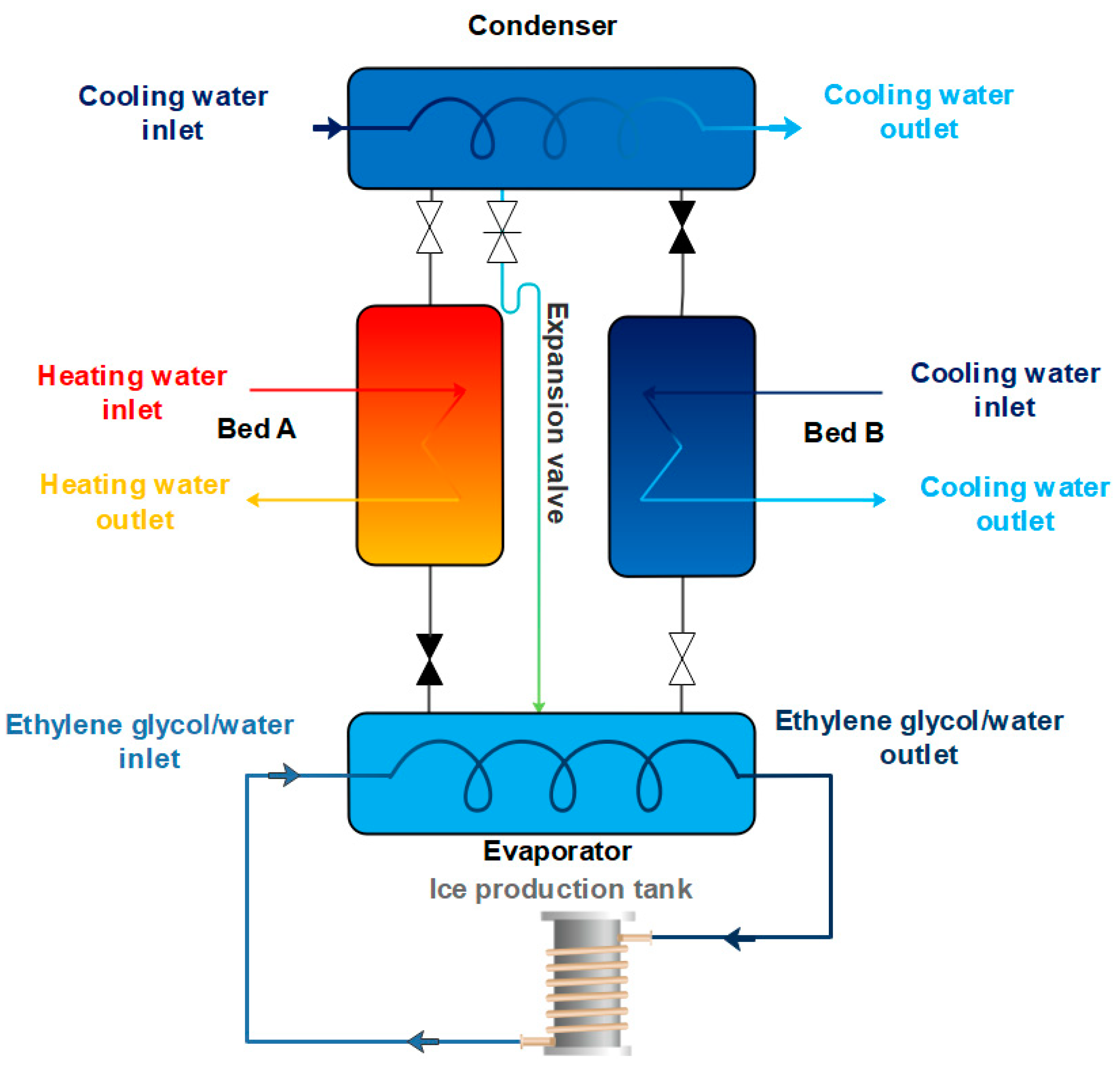
The two-bed configuration of an adsorption ice production system is employed in this study to examine using a composite adsorbent of 50% Maxsorb III with 10% PVA and 40% graphene nanoplatelets. Producing ice can be accomplished by circulating ethylene glycol that enters the evaporator of the ARS at −2 °C with an external ice production block as shown in Figure 1. The composite adsorbent is applied on the external surface of plain copper tubes in the adsorbent bed, where the heating and cooling fluids are pumped inside the tubes. Heating and cooling water are switched between the two beds during the four processes (preheating, desorption, precooling, and adsorption) to complete a one-bed cycle. Switching valves are used to connect the evaporator and condenser with the sorption beds depending on the mode of operation.
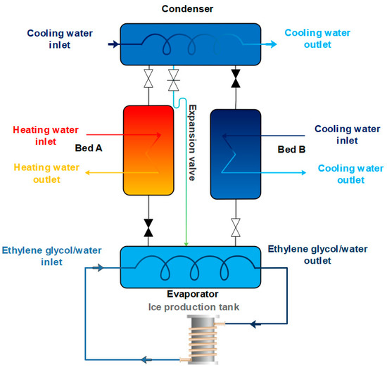
Figure 1.
Schematic diagram of an adsorption system used for ice production.
2.1. Mathematical Modelling
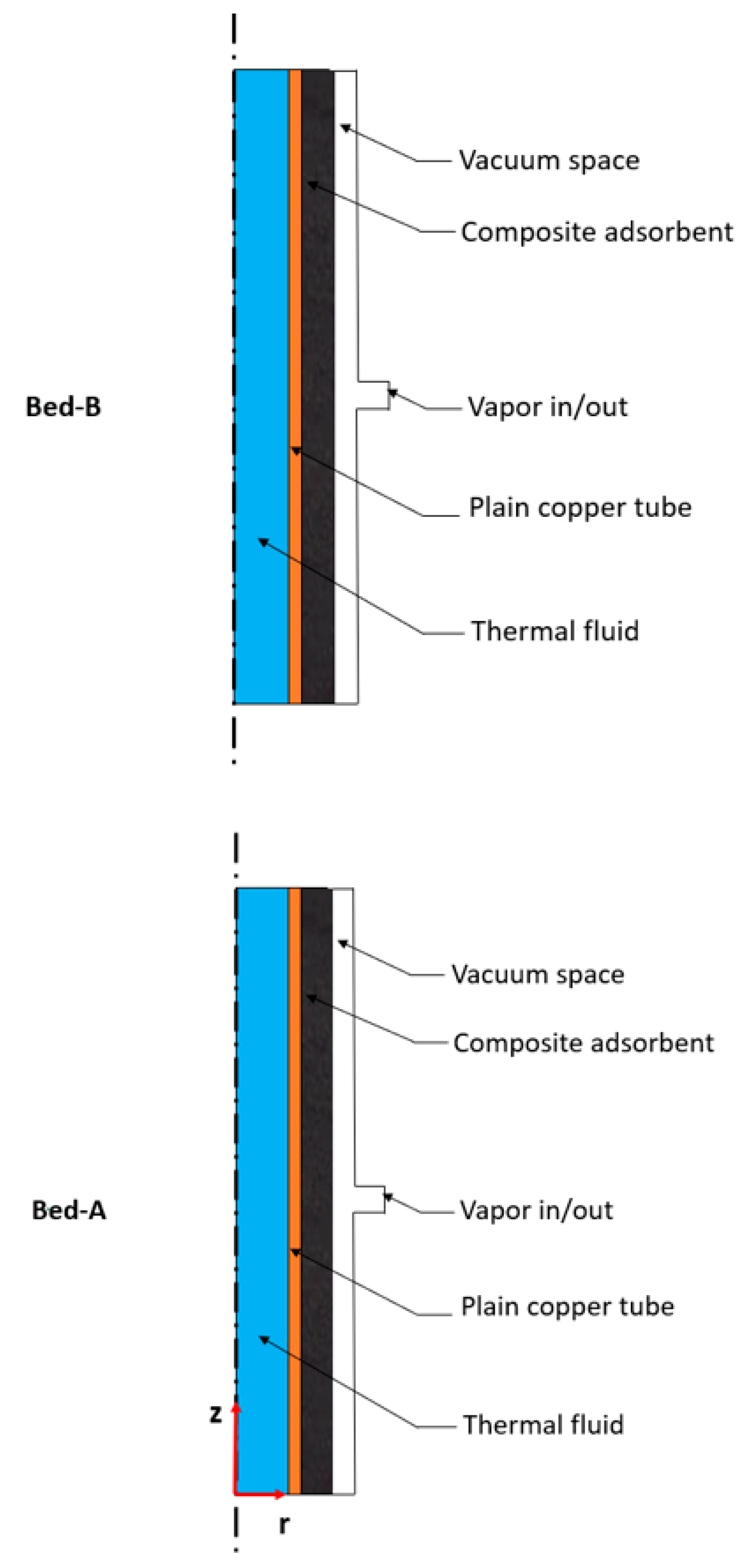
A time-dependent fully coupled numerical model is employed in the present study to simultaneously simulate the performance of the two composite adsorbent beds. Two representative adsorber tubes, one for each bed, are used in the simulation, as each bed consists of several parallel identical tubes. Unlike the previous studies that used thermodynamic or lumped models to evaluate the system performance, a thorough numerical model is developed in the present study for a carbon-based composite in a consolidated form. The model simulates the two-bed adsorption system performance depending on the microscopic details of the composite adsorbent. The model is employed to produce ice which necessitates the operation under relatively low pressures in the evaporator compared to conventional cooling operation. 2-D axisymmetric schemes of the representative adsorber tubes are adopted in COMSOL Multiphysics as shown in Figure 2. The tubes include the main four domains, which are the thermal fluid, plain copper tube, composite adsorbent, and vacuum space domains. In an adsorption ice production system, the vapor will enter the beds at relatively lower pressures and temperatures compared to conventional cooling applications. That makes considering the time variations of the temperature lift (the difference between the condensing and evaporating temperatures) more critical. Therefore, the equations of energy balances for the condenser and evaporator are applied at the vapor inlet/outlet boundaries of each representative adsorber tube. These equations consider the thermal masses and overall heat transfer coefficients of both components to determine the pressures and temperatures at those boundaries. The following general assumptions are considered in adopting the governing equations:

Figure 2.
The two-dimensional axisymmetric domains applied in the mathematical modelling.
The ethanol vapor behaves as an ideal gas.
The composite adsorbent is homogonous and its porosity is isotropic.
Ethanol vapor, adsorbate, and composite adsorbent are at local thermal equilibrium.
2.2. Governing Equations
2.2.1. Heating and Cooling Fluids
Using RANS equations to describe the turbulent flow scheme for incompressible water flowing inside the absorber tubes leads to the following mass, momentum, and energy equations, respectively:
The thermal turbulent conductivity (kT) accounts for the enhancement in conductive heat transfer term due the turbulence [29].
2.2.2. Absorber Copper Tube
The energy conservation equation for the heat transfer tube reflecting only the conduction mechanism can be written as:
2.2.3. Composite Adsorbent Domain
The mass balance for the composite adsorbent in the consolidated form can be written as [16]:
where is the composite adsorbent total porosity, X is the instant uptake, is the ethanol density in vapor phase, is the composite adsorbent density, and is the volume-averaged velocity.
The momentum equations that govern the composite adsorbent field can be adapted as follows:
The modified Navier–Stokes equations in the above form account for the homogeneous fluid flow inside porous domain including the effect of adsorption/desorption rates on the momentum balances. In addition, using these equations’ form is necessary for coupling the variables at the interface with the vacuum domain [29]. Qm is the source term used in Equation (5) and can be rewritten as:
The conservation of energy for the composite adsorbent field can be given as:
where the effective thermal capacity ( of the composite adsorbent can be expressed as follows:
Hads is the heat of adsorption and kcomp is the effective thermal conductivity of the composite adsorbent.
2.2.4. Vacuum Chamber
The conservation equations for mass, momentum, and energy balances used for the vacuum space to describe the laminar flow scheme of the ethanol vapor can be expressed, respectively, as follows:
2.2.5. Evaporator and Condenser Models
The evaporator and condenser heat balance equations can be used to determine the temperature of the evaporation and condensation, respectively. Therefore, the time variation of the corresponding pressures of both components will reflect the influence of their thermal masses and heat transfer efficiency. The following lumped models are used at the valve openings of the two representative tubes of the two beds.
The effectiveness of the evaporator and condenser can be determined as follows:
where Ntube,adsorber is the number of tubes used in each the adsorber. α and β are flags applied for simulating the situation of the connecting valves (on/off) that connect each adsorber to the evaporator and condenser.
2.2.6. Isotherms and Kinetics Models
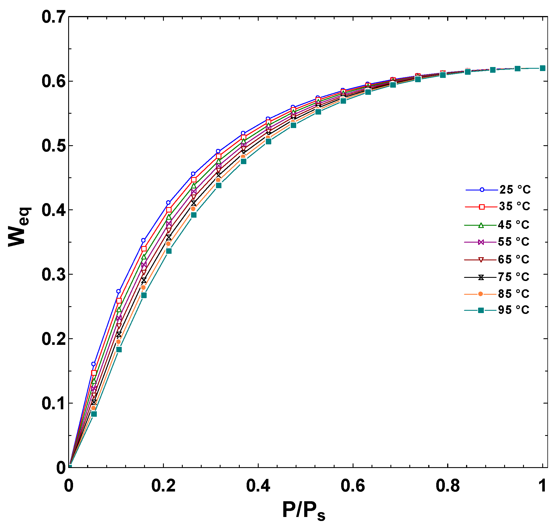
The equilibrium uptake can be determined from isotherms equations defined for the investigated composite adsorbent/ethanol pair [26]:
where Xmax is the maximum adsorption capacity, E is the adsorption characteristics parameter, and n is the heterogeneity parameter.The isotherms of the composite adsorbent/ethanol pair are plotted in Figure 3.

Figure 3.
The isotherms of the given consolidated composite adsorbent/ethanol pair.
The linear-driving-force equation is typically applied for simulating the kinetics of the given adsorbent material which can be written as [22,26]:
where KLDF is the mass transfer coefficient and it can be expressed as follows:
where is 15 for spherical shape, and the parameter is described by Arrhenius equation as a function of the local temperature as follows:
2.2.7. Performance Indicators
The system performance is evaluated by numerical integration of the change in thermal fluid temperatures to calculate the refrigeration capacity and regeneration capacity as follows:
The coefficient of performance (COP), and specific daily ice production (SDIP) can be defined as follows:
where Mcomp is the composite mass of adsorbent material calculated for the two sorption beds while n is the total cycles per day.
The set of parameters used in the simulation for the two beds is shown in Table 1. The condenser and evaporator parameters and the details of the initial and boundary conditions are provided in the Supplementary Materials.

Table 1.
The values of the parameters set in the simulation model.
2.2.8. Numerical Procedure and Model Validation
The system of equations described in this study was solved simultaneously by adopting six physics in COMSOL Multiphysics software. The coupling among the equations for the solved parameters was ensured via the Multiphysics options in which non-isothermal flow was solved for the internal flow in the tubes and the flow in porous and free spaces domains. Furthermore, the time variations of the pressures of the condenser and evaporator were reflected at the valve opening boundaries using adjustable physics namely Ordinary Differential Equations. The source terms in modified physics were programmed and imposed in the conventional equations using user-defined variable options. The number of mesh used was about 506,664 mesh elements with average mesh quality of 0.86 and considering an adequate number of meshes at the boundaries where the variables are undergoing high gradients. The segregated technique with MUMPS and PARDISO solvers was employed to establish the final solutions with acceptable accuracy. The time step in the switching modes was as low as 0.1 s to catch the rapid change in the main variables during the short switching mode time while it was set to 1 s during the adsorption and regeneration modes. A physics-controlled choice that considers the type of equations solved for each physics was adopted in the mesh builder to set excessive mesh elements close to walls where variables have higher gradients. The extra-fine mesh choice was used with about 464,044 triangular elements and 42,620 quadratic elements for the model of the composite thickness of 2 mm. The maximum growth rate at the boundary of the thermal fluid domain was 1.08 and the maximum growth rate at the boundary of the composite adsorbent and the vacuum chamber domains was 1.1. Increasing the number of meshes over the previously specified level showed an insignificant effect on the results, where a maximum variation of 0.15% in the COP and SDIP was reported.
For the given case, the validity of the present model was compared with the published data by Pinheiro, et al. [34] for the time variations of the temperature and uptake as shown in Figure 4. An excellent agreement between the results can be noticed, which confirms the reliability of the present system of equations to simulate the adsorption system performance. More details about the model validation can be accessed in references [30,35,36].

Figure 4.
The comparison between the data obtained from the present study and those published in reference [34].
3. Results and Discussion
The pressure and temperature of the composite adsorbent determine the equilibrium uptake which represents the maximum and minimum uptake capacity that can be attained during the adsorption and desorption phases, respectively, at a given time. However, the intraparticle and interparticle mass transfer resistances indicate how fast the adsorbent material can approach its equilibrium uptake capacity in each given case. This highlights the importance of solving both the mass transfer mechanisms simultaneously with the other governing equations in the present study to show up the net effect of boosting the heat transfer on accounts of the mass transfer. Therefore, the effect of using the carbon-based composite adsorbent in the consolidated form with thicknesses of 2, 5, and 10 mm on the overall performance of a two-bed adsorption ice production system are examined at different cycle time ranged from 430 to 1230 s. The total amount of the composite material of 4.76 kg is fixed in all cases by changing the total number of tubes. The numerical simulations of the composite domain are used to show up the temporal and spatial changes of the temperature and the uptake for the duration of one of the complete cyclic processes. The detailed model developed in the present study shows the net effects of adding the graphene nanoparticles as additives with high thermal conductivity on the ice production and the energy conversion efficiency of the adsorption system. This can help in designing the composite adsorbent bed and selecting the most appropriate cycle time.
3.1. Numerical Simulation
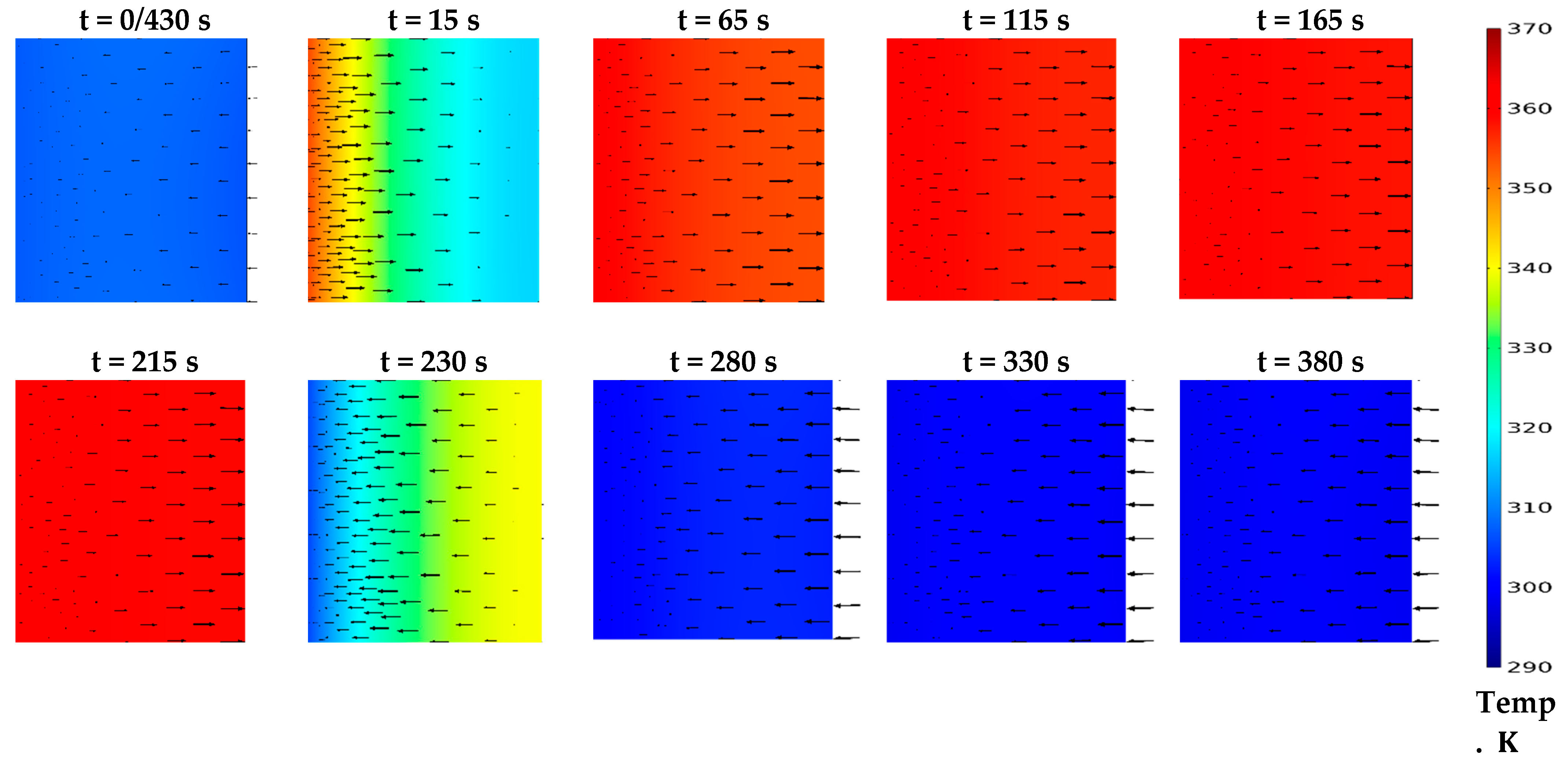
Figure 5 shows the temperature distribution of the consolidated adsorbent domain for a representative section at intervals of time during 430 s cycle time considering 30 s for both preheating and precooling phases. The section area has a 5 mm composite thickness. The average temperature of the selected section was 300.84 K at the start of the new cycle and after only 15 s it reached 328.31 K affected by the enhancement of the thermal conductivity of the composite adsorbent. The average temperature reached 359.87 K at the end of the desorption process after 215 s which was only 3.13 K less than the regeneration temperature of 363 K. At the end of the precooling process after 230 s, the average temperature reached 330.81 K, and it reduced to 302.01 K at the end of the adsorption process after 430 s. The arrows appearing in the figure represent the velocity magnitude and direction of the vapor
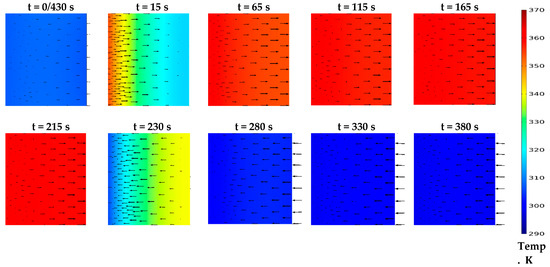
Figure 5.
The temperature distribution during the whole cycle at different time steps for the consolidated form.
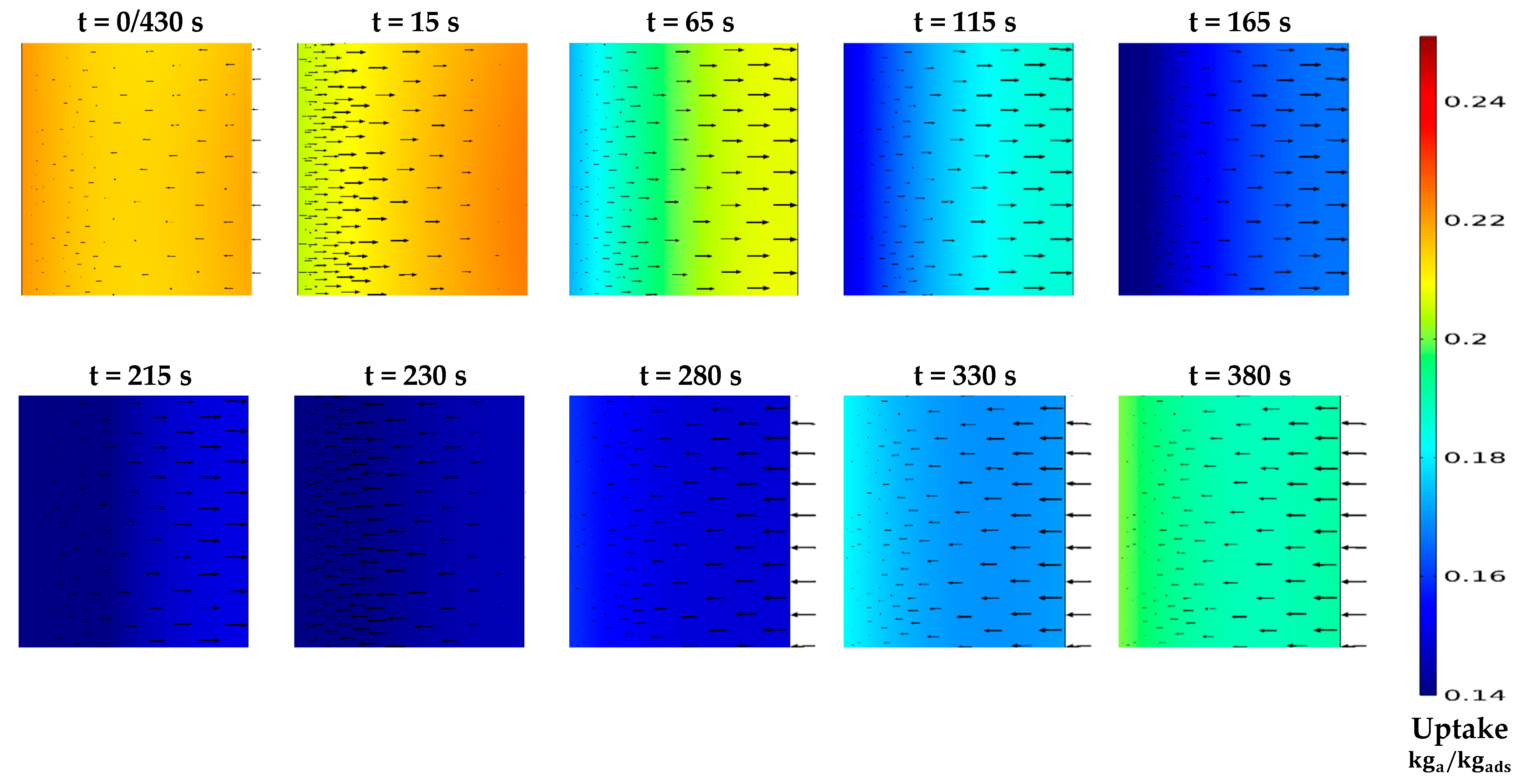
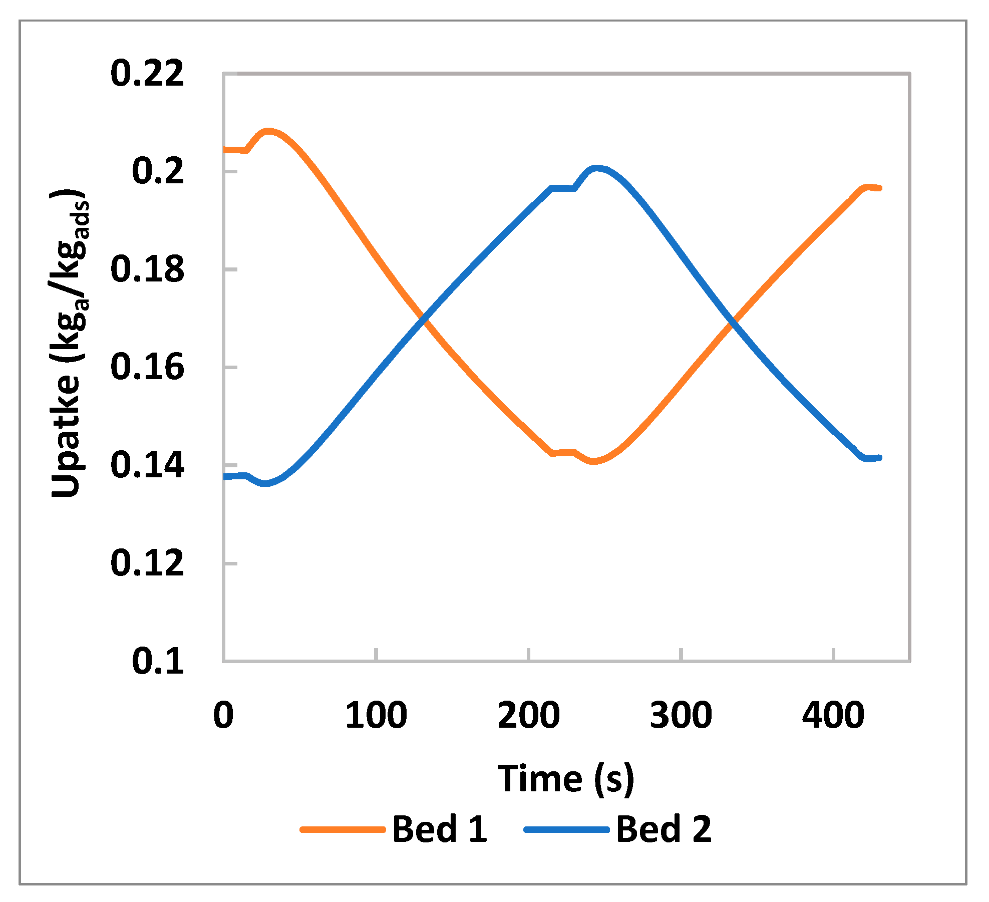
Figure 6 shows how the spatial variation of the instantaneous uptake responds to the heat transfer enhancement achieved using graphene nanoplatelets in carbon-based composite adsorbent. For the selected section, the average uptake was 0.14264 at the end of the precooling process of the previous cycle. During the preheating process, the amount released from the composite domain was used to build up the pressure in the bed vacuum space before opening the connecting valve with the condenser. Therefore, the change in the average uptake was hardly noticed due to the accumulation of the desorbed amount coming from the adsorbent near the tube side to the other side near to the vacuum space. After opening the connecting valve and the desorption process has taken place, the average amount of the uptake reduced gradually from 0.2044 at 15 s to 0.198, 0.176 and 0.158 at 65, 115 and 165 s, respectively. Despite the spatial variation of the temperature being less noticed with the progress of time, a relatively high spatial variation of the uptake can be noticed in Figure 6. This can be attributed to the increased interparticle mass transfer resistance caused by the lower total porosity of the composite adsorbent estimated by 0.3483. As a result, the effective uptake, which represents the difference between the maximum and minimum uptake, was limited to only 0.062 in the complete cycle during the cyclic steady state at the given condition, as shown in Figure 7.

Figure 6.
The uptake distribution during the whole cycle at different time steps for the consolidated form.

Figure 7.
The average uptake of the two beds over a complete cycle.
3.2. The Bed Average Pressure, Temperature and Uptake
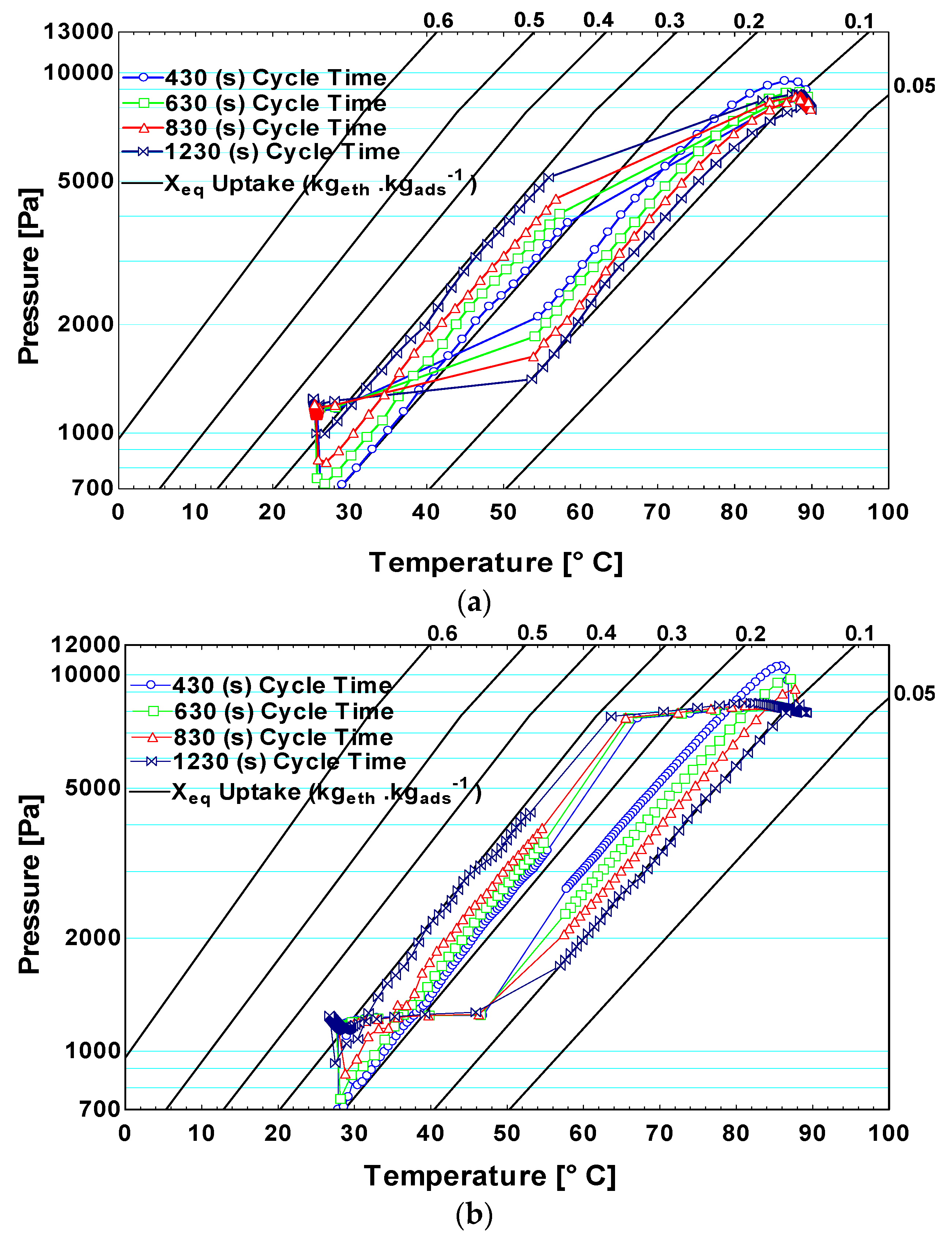
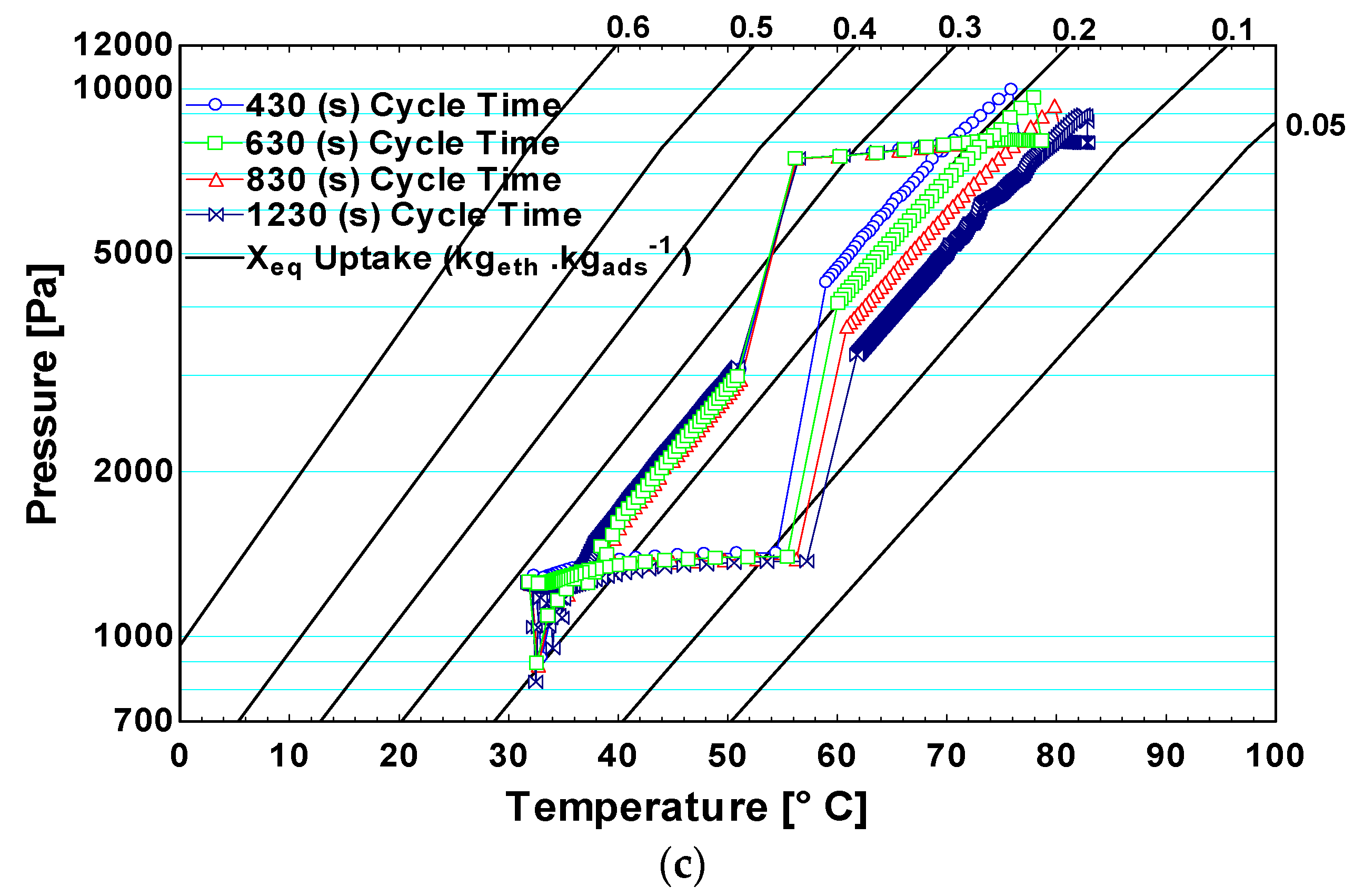
Figure 8 illustrates the cyclic change of the averaging of the bed’s main parameters, which are the pressure, the temperature, and the uptake, at different cycle times and composite thicknesses. In general, the effective uptake during a complete cycle increases with increasing the cycle time, while it decreases with increasing the composite thickness. The hysteresis of the adsorbate in the beds during repeated adsorption and desorption processes was reduced with a longer cycle time. This can be indicated by the increase in the enclosed area of each cycle at higher cycle time, as shown in Figure 8a–c at different composite thicknesses. The additives and binder represent 50% of the carbon-based composite in the present study which reduced the total porosity to 0.3483 even though the highly porous carbon type Maxsorb III was used. This low porosity has a considerable impact on the interparticle mass transfer, particularly when the composite thickness is increased. Therefore, increasing the composite thickness from 2 to 10 mm decreases noticeably the effective uptake.


Figure 8.
P-T-Xeq diagram for the carbon-based composite adsorbent bed in a complete cycle under different cycle times and composite thicknesses of (a) 2 mm, (b) 5 mm, and (c) 10 mm.
In case of 10 mm composite thickness shown in Figure 8c the positive effect of the longer cycle time was more pronounced during the desorption process as it decreased the lower uptake limit. However, the upper limit of the uptake during the adsorption process was slightly increased with increasing the cycle time. This was affected by applying the very lower pressure level in the beds during the adsorption process to keep the evaporator under −2 °C combined with the higher composite thickness used.
The Performance of the Ice Production System
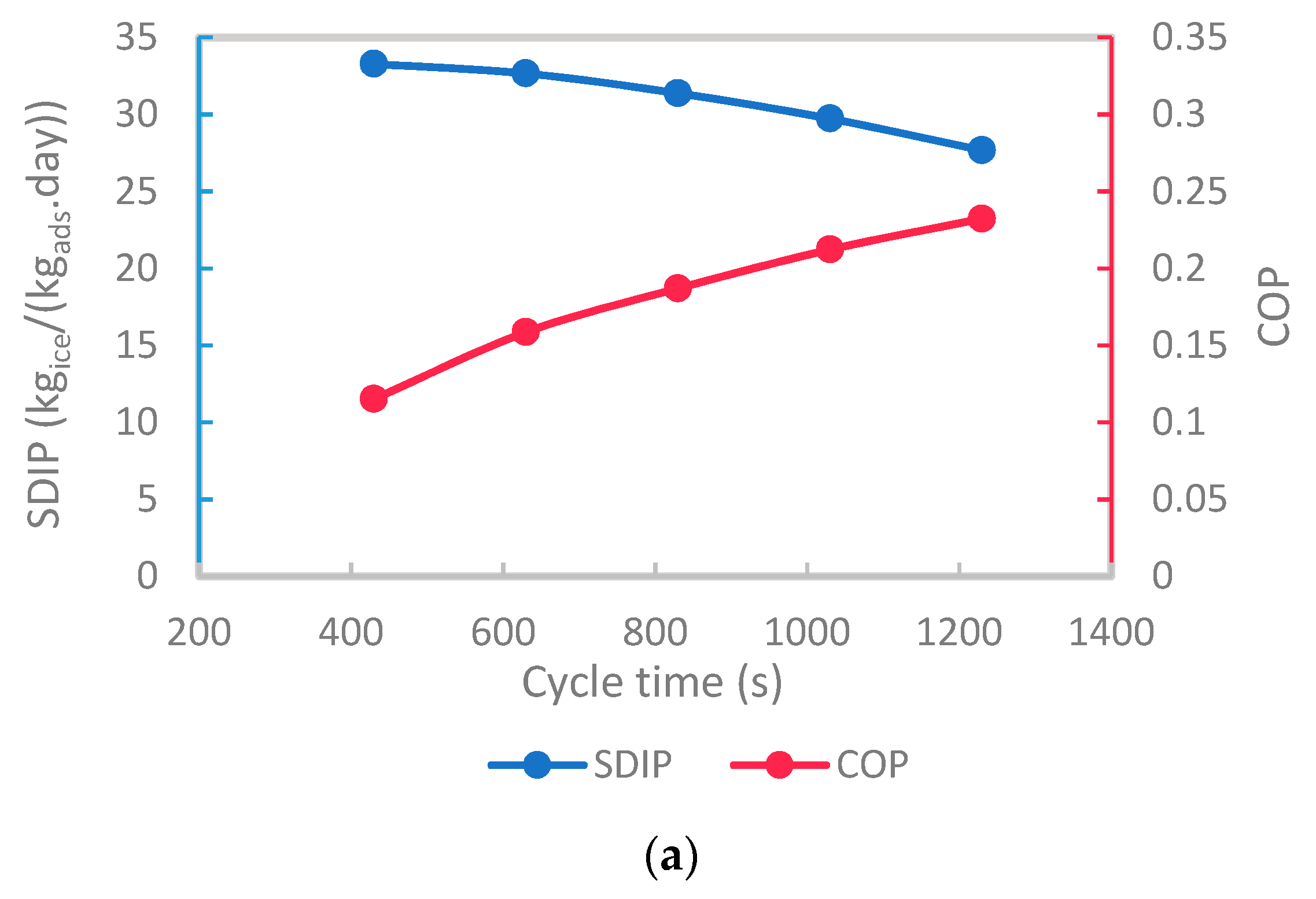
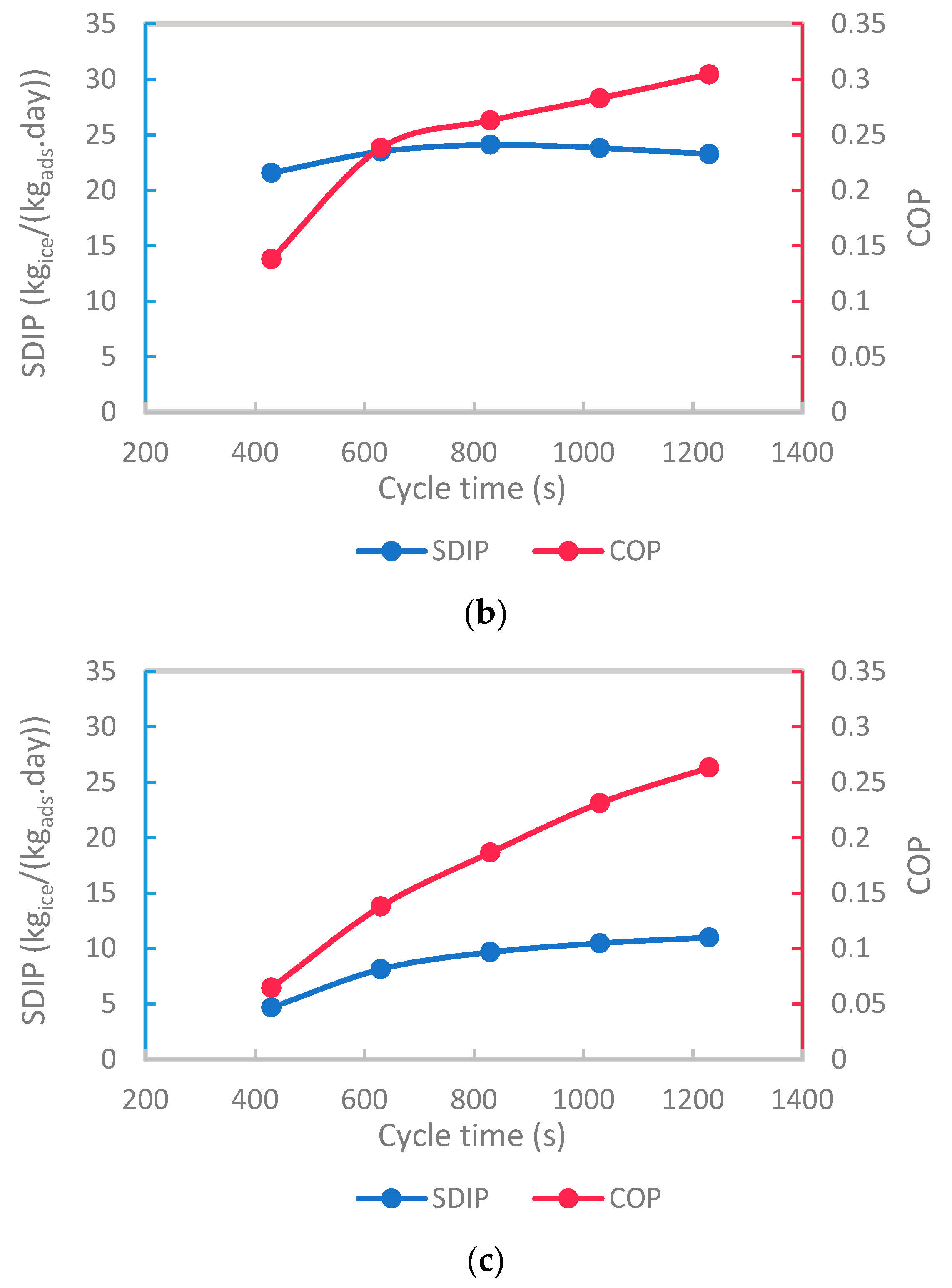
The net impacts of the changing of the cycle times on the SDIP and COP of the ice production system at composite thicknesses of 2, 5, and 10 mm are shown in Figure 9. Overall, increasing the cycle time, in the given range, can either increase or decrease the SDIP of the system depending on the composite thickness. However, the COP of the system has increased by increasing the cycle time regardless of the composite thickness. A maximum SDIP of 33.27 kgice·kgads−1·day−1 was attained at the shortest cycle time of 430 s and the smallest composite thickness of 2 mm. Nevertheless, the system COP reached its maximum value of 0.3046 at the longer cycle time of 1230 with 5 mm composite thickness, and the SDIP associated with this case was 23.27 kgice·kgads−1·day−1. The changing range of the SDIP over different cycle times was considerably reduced by increasing the composite thickness as it can be seen by comparing the range of the SDIP given in Figure 9a–c. This was attributed to the reduction in the effective uptake with thicker composite thickness.


Figure 9.
The specific daily ice production and coefficient of performance of the system under different cycle times and composite thicknesses of (a) 2 mm, (b) 5 mm, and (c) 10 mm.
In the case of 2 mm composite thickness, the SDIP decreased gradually from its maximum value of 33.27 kgice·kgads−1·day−1 at 430 s to 27.66 kgice·kgads−1·day−1 at 1230 s. This reduction was affected by the slower adsorption and desorption rates at a higher cycle time as the instantaneous uptake approached the equilibrium uptake in a short time. However, this was not the case with 5 mm composite thickness, as depicted in Figure 9b, as the kinetics remained at a higher level for a longer time compared with the case of 2 mm composite thickness. Therefore, the maximum SDIP of 24.1 kgice·kgads−1·day−1 with 5 mm composite thickness was attained at 830 s. The slower adsorption and desorption rates at a higher cycle time of more than 830 s hampered the increase in the SDIP that started to be reduced. Consequentially, in this case, the rate of increase of the COP was reduced as shown in Figure 9b. In the case of the composite thickness of 5 mm, the COP was enhanced at all cycle times compared to the case of 2 mm composite thickness. This was in response to the decrease in the number of tubes from 309 at 2 mm to 95 at 5 mm composite thickness.
In the case of the composite thickness of 10 mm, a higher cycle time was needed to overcome the increase in both interparticle and intraparticle mass transfer resistances associated with higher composite thickness and improve the system performance. The best SDIP of 11 kgice·kgads−1·day−1 and the best COP of 0.263, in this case, were attained at a cycle time of 1230 s. Although the performance was the worst in this case, the lower number of tubes used can considerably reduce the flow rates of the heating and cooling water, which may be needed with an adsorption system of large capacity to reduce the pumping power. Generally, the results showed a discrepancy between the effect of varying the composite thickness and cycle time on both the system SDIP and COP. This highlights the importance of concurrent solution of mass and heat transfer resistances in evaluating the overall performance of the adsorption ice maker that uses the activated carbon composite with additives in a consolidated form. One can choose the best combination of the composite thickness with the corresponding cycle time to achieve either the best COP or the best SDIP depending on the primary concern and application.
4. Conclusions
Using a carbon-based composite in a consolidated form, which combines 50% carbon type Maxsorb III with 40% graphene nanoplatelets and 10% binder, was numerically examined on an adsorption system level. The system is used to produce ice from ethylene glycol at temperatures less than −2 °C. The composite adsorbent was primarily proposed to enhance the thermal conductivity of Maxsorb III seeking out a higher overall adsorption system performance. The present study aimed to highlight, at the system level, the inconsistent effects of the heat transfer and mass transfer within the adsorbent bed due to using the consolidated form in an adsorption ice production system. The main outcomes can be deduced as follows:
Using the composite adsorbent layer of 2 mm and cycle time of 430 s, which were the smallest in the investigated ranges, led to the highest specific daily ice production of 33.27 kgice·kgads−1·day−1 with a corresponding COP of 0.115. The maximum COP of 0.3046 was attained when employing composite adsorbent thickness of 5 mm and cycle time of 1230 s. The largest adsorbent thickness of 10 mm reduced dramatically the SDIP and COP to be maximum at 11.01 kgice·kgads−1·day−1 and 0.2632 at the cycle time of 1230 s.
Although extending the cycle time increased the effective uptake, the kinetics played important role in determining the SDIP of the ice production system that uses carbon-based composite adsorbent in the consolidated form. On the other side, the reduction in the total number of tubes used in each adsorbent bed prompted the system energy conversion efficiency in terms of the COP due to using the use of a lower heating water flow rate and reduced energy share used for sensible heating at each cycle.
The case of the best COP can be used when the source of energy is costly and takes the priority to be as minimum as possible. In the case of using solar energy to drive the system, the higher COP will reduce the system footprint and capital cost. From a practical point of view, using the adsorbent material in a consolidated form can ease the adsorbent bed assembling and avoid the blocking and the increase of the pressure drop due to the fine net used in the packing technique. However, future studies should focus on decreasing the mass transfer resistances of the adsorbent layer in the consolidated form to attain a higher system performance.
Supplementary Materials
The following supporting information can be downloaded at: https://www.mdpi.com/article/10.3390/app12157602/s1.
Author Contributions
Conceptualization, M.B.E.; data curation, M.S.E., J.O., A.E.-L. and O.E.; formal analysis, J.O. and O.E.; funding acquisition, H.A.-A.; investigation, M.B.E., M.S.E. and J.O.; methodology, M.B.E.; project administration, H.A.-A.; resources, A.E.-L.; software, M.B.E. and M.S.E.; supervision, H.A.-A.; validation, M.S.E.; visualization, A.E.-L.; writing—original draft, M.B.E.; writing—review and editing, M.B.E. and O.E. All authors have read and agreed to the published version of the manuscript.
Funding
This Project was funded by the National Plan for Science, Technology and Innovation (MAARIFAH), King Abdulaziz City for Science and Technology, Kingdom of Saudi Arabia, Award Number (ll-ENE1845-02).
Institutional Review Board Statement
Not applicable.
Informed Consent Statement
Not applicable.
Conflicts of Interest
The authors declare no conflict of interest.
Nomenclature
| Coefficient of performance | |
| Specific heat | |
| Surface diffusivity | |
| Pre-exponent constant of surface diffusivity | |
| Specific Daily ice production | |
| The activation energy of surface diffusion | |
| Thermal conductivity | |
| Thermal turbulent conductivity | |
| Mass transfer coefficient | |
| Latent heat | |
| Mass | |
| Completed cycles per day | |
| Pressure | |
| Source term in conservation of mass equation | |
| Heat of adsorption | |
| Specific gas constant | |
| Radius | |
| Temperature | |
| Time | |
| Heat transfer conductance | |
| Fluid velocity | |
| Uptake | |
| Equilibrium adsorption uptake | |
| Greek Symbols: | |
| Density ) | |
| Dynamic viscosity | |
| Turbulent dynamic viscosity | |
| Total porosity | |
| Effectiveness | |
| Subscripts and Superscripts: | |
| Adsorbent | |
| Adsorbate | |
| Bed | |
| Cooling water | |
| Condenser | |
| Composite | |
| Ethylene Glycol | |
| Evaporator | |
| Equilibrium | |
| Fluid | |
| Heating water | |
| Inlet | |
| Initial | |
| Metal | |
| Outlet | |
| Refrigerant liquid | |
| Refrigerant Vapor | |
| Solid Adsorbent | |
| Saturation | |
| Vapor | |
| water | |
References
- Sah, R.P.; Choudhury, B.; Das, R.K. A review on low grade heat powered adsorption cooling systems for ice production. Renew. Sustain. Energy Rev. 2016, 62, 109–120. [Google Scholar] [CrossRef]
- Chauhan, P.; Kaushik, S.; Tyagi, S. A review on thermal performance enhancement of green cooling system using different adsorbent/refrigerant pairs. Energy Convers. Manag. X 2022, 14, 100225. [Google Scholar] [CrossRef]
- Elsheniti, M.B.; El-Hamid, A.A.; Samni, O.E.; Elsherbiny, S.; Elsayed, E. Experimental evaluation of a solar two-bed lab-scale adsorption cooling system. Alex. Eng. J. 2021, 60, 2747–2757. [Google Scholar] [CrossRef]
- Sharafian, A.; Fayazmanesh, K.; McCague, C.; Bahrami, M. Thermal conductivity and contact resistance of mesoporous silica gel adsorbents bound with polyvinylpyrrolidone in contact with a metallic substrate for adsorption cooling system applications. Int. J. Heat Mass Transf. 2014, 79, 64–71. [Google Scholar] [CrossRef]
- Yagnamurthy, S.; Rakshit, D.; Jain, S.; Rocky, K.A.; Islam, A.; Saha, B.B. Adsorption of difluoromethane onto activated carbon based composites: Thermophysical properties and adsorption characterization. Int. J. Heat Mass Transf. 2021, 171, 121112. [Google Scholar] [CrossRef]
- Pal, A.; El-Sharkawy, I.I.; Saha, B.B.; Jribi, S.; Miyazaki, T.; Koyama, S. Experimental investigation of CO2 adsorption onto a carbon based consolidated composite adsorbent for adsorption cooling application. Appl. Therm. Eng. 2016, 109, 304–311. [Google Scholar] [CrossRef] [Green Version]
- Kumita, M.; Yamawaki, N.; Shinohara, K.; Higashi, H.; Kodama, A.; Kobayashi, N.; Seto, T.; Otani, Y. Methanol adsorption behaviors of compression-molded activated carbon fiber with PTFE. Int. J. Refrig. 2018, 94, 127–135. [Google Scholar] [CrossRef]
- Pal, A.; Shahrom, M.S.R.; Moniruzzaman, M.; Wilfred, C.D.; Mitra, S.; Thu, K.; Saha, B.B. Ionic liquid as a new binder for activated carbon based consolidated composite adsorbents. Chem. Eng. J. 2017, 326, 980–986. [Google Scholar] [CrossRef]
- El-Sharkawy, I.I.; Pal, A.; Miyazaki, T.; Saha, B.; Koyama, S. A study on consolidated composite adsorbents for cooling application. Appl. Therm. Eng. 2016, 98, 1214–1220. [Google Scholar] [CrossRef] [Green Version]
- Jin, Z.; Tian, B.; Wang, L.; Wang, R. Comparison on Thermal Conductivity and Permeability of Granular and Consolidated Activated Carbon for Refrigeration. Chin. J. Chem. Eng. 2013, 21, 676–682. [Google Scholar] [CrossRef]
- Cacciola, G.; Restuccia, G.; Mercadante, L. Composites of activated carbon for refrigeration adsorption machines. Carbon 1995, 33, 1205–1210. [Google Scholar] [CrossRef]
- Wang, L.; Wang, R.; Lu, Z.; Chen, C.; Wang, K.; Wu, J. The performance of two adsorption ice making test units using activated carbon and a carbon composite as adsorbents. Carbon 2006, 44, 2671–2680. [Google Scholar] [CrossRef]
- Oliveira, R.G.; Wang, R.Z. A consolidated calcium chloride-expanded graphite compound for use in sorption refrigeration systems. Carbon 2007, 45, 390–396. [Google Scholar] [CrossRef]
- Rocky, K.A.; Pal, A.; Moniruzzaman, M.; Saha, B.B. Adsorption characteristics and thermodynamic property fields of polymerized ionic liquid and polyvinyl alcohol based composite/CO2 pairs. J. Mol. Liq. 2019, 294, 111555. [Google Scholar] [CrossRef]
- Wang, L.; Tamainot-Telto, Z.; Thorpe, R.; Critoph, R.; Metcalf, S.; Wang, R. Study of thermal conductivity, permeability, and adsorption performance of consolidated composite activated carbon adsorbent for refrigeration. Renew. Energy 2011, 36, 2062–2066. [Google Scholar] [CrossRef]
- Zhao, Y.; Wang, L.; Wang, R.; Jin, Z.Q.; Jiang, L.; Fleurance, M. Simulation of heat and mass transfer performance with consolidated composite activated carbon. Heat Transf. Res. 2015, 46, 109–122. [Google Scholar] [CrossRef]
- Wang, L.; Metcalf, S.; Critoph, R.; Thorpe, R.; Tamainot-Telto, Z. Development of thermal conductive consolidated activated carbon for adsorption refrigeration. Carbon 2012, 50, 977–986. [Google Scholar] [CrossRef] [Green Version]
- Jjagwe, J.; Olupot, P.W.; Menya, E.; Kalibbala, H.M. Synthesis and Application of Granular Activated Carbon from Biomass Waste Materials for Water Treatment: A Review. J. Bioresour. Bioprod. 2021, 6, 292–322. [Google Scholar] [CrossRef]
- Ghazy, M.; Askalany, A.; Kamel, A.; Khalil, K.M.; Mohammed, R.H.; Saha, B.B. Performance enhancement of adsorption cooling cycle by pyrolysis of Maxsorb III activated carbon with ammonium carbonate. Int. J. Refrig. 2020, 126, 210–221. [Google Scholar] [CrossRef]
- Shabir, F.; Sultan, M.; Miyazaki, T.; Saha, B.B.; Askalany, A.; Ali, I.; Zhou, Y.; Ahmad, R.; Shamshiri, R.R. Recent updates on the adsorption capacities of adsorbent-adsorbate pairs for heat transformation applications. Renew. Sustain. Energy Rev. 2019, 119, 109630. [Google Scholar] [CrossRef]
- Boruta, P.; Bujok, T.; Mika, Ł.; Sztekler, K. Adsorbents, Working Pairs and Coated Beds for Natural Refrigerants in Adsorption Chillers—State of the Art. Energies 2021, 14, 4707. [Google Scholar] [CrossRef]
- Jribi, S.; Miyazaki, T.; Saha, B.B.; Koyama, S.; Maeda, S.; Maruyama, T. Corrected adsorption rate model of activated carbon–ethanol pair by means of CFD simulation. Int. J. Refrig. 2016, 71, 60–68. [Google Scholar] [CrossRef]
- Khanam, P.N.; AlMaadeed, M.A.; Ouederni, M.; Mayoral, B.; Hamilton, A.; Sun, D. Effect of two types of graphene nanoplatelets on the physico–mechanical properties of linear low–density polyethylene composites. Adv. Manuf. Polym. Compos. Sci. 2016, 2, 67–73. [Google Scholar] [CrossRef] [Green Version]
- Geng, Y.; Wang, S.J.; Kim, J.-K. Preparation of graphite nanoplatelets and graphene sheets. J. Colloid Interface Sci. 2009, 336, 592–598. [Google Scholar] [CrossRef] [PubMed]
- Pal, A.; Uddin, K.; Thu, K.; Saha, B.B. Activated carbon and graphene nanoplatelets based novel composite for performance enhancement of adsorption cooling cycle. Energy Convers. Manag. 2018, 180, 134–148. [Google Scholar] [CrossRef]
- Rupa, M.J.; Pal, A.; Saha, B.B. Activated carbon-graphene nanoplatelets based green cooling system: Adsorption kinetics, heat of adsorption, and thermodynamic performance. Energy 2019, 193, 116774. [Google Scholar] [CrossRef]
- Elsheniti, M.B.; Rezk, A.; Shaaban, M.; Roshdy, M.; Nagib, Y.M.; Elsamni, O.A.; Saha, B.B. Performance of a solar adsorption cooling and desalination system using aluminum fumarate and silica gel. Appl. Therm. Eng. 2021, 194, 117116. [Google Scholar] [CrossRef]
- Ingham, D.B.; Pop, I. Transport Phenomena in Porous Media; Elsevier: Amsterdam, The Netherlands, 1998. [Google Scholar]
- Elsheniti, M.B.; Hassab, M.A.; Attia, A.-E. Examination of effects of operating and geometric parameters on the performance of a two-bed adsorption chiller. Appl. Therm. Eng. 2019, 146, 674–687. [Google Scholar] [CrossRef]
- Albaik, I.; Elsheniti, M.B.; Al-Dadah, R.; Mahmoud, S.; Solmaz, I. Numerical and experimental investigation of multiple heat exchanger modules in cooling and desalination adsorption system using metal organic framework. Energy Convers. Manag. 2021, 251, 114934. [Google Scholar] [CrossRef]
- Wong, D.; Parasrampuria, J. Polyvinyl Alcohol. In Analytical Profiles of Drug Substances and Excipients; Academic Press: Cambridge, MA, USA, 1996; Volume 24, pp. 397–441. [Google Scholar]
- American Elements. Graphene Nanoplatelets. Available online: https://www.americanelements.com/graphene-nanoplatelets-1034343-98-0 (accessed on 8 July 2021).
- XG Sciences. Graphene Nanoplatelets. Available online: https://xgsciences.com/materials/graphene-nano-platelets/ (accessed on 10 July 2021).
- Pinheiro, J.M.; Salústio, S.; Geraldes, V.; Valente, A.A.; Silva, C.M. Copper foam coated with CPO-27(Ni) metal–organic framework for adsorption heat pump: Simulation study using OpenFOAM. Appl. Therm. Eng. 2020, 178, 115498. [Google Scholar] [CrossRef]
- Shaaban, M.; Elsheniti, M.B.; Rezk, A.; Elhelw, M.; Elsamni, O.A. Performance investigation of adsorption cooling and desalination systems employing thermally enhanced copper foamed bed coated with SAPO-34 and CPO-27(Ni). Appl. Therm. Eng. 2022, 205, 118056. [Google Scholar] [CrossRef]
- Elsheniti, M.B.; Eissa, M.S.; Al-Ansary, H.; Orfi, J.; Elsamni, O.; El-Leathy, A. Examination of Using Aluminum-Foam/Finned-Tube Beds Packed with Maxsorb III for Adsorption Ice Production System. Energies 2022, 15, 2757. [Google Scholar] [CrossRef]

Publisher’s Note: MDPI stays neutral with regard to jurisdictional claims in published maps and institutional affiliations. |
© 2022 by the authors. Licensee MDPI, Basel, Switzerland. This article is an open access article distributed under the terms and conditions of the Creative Commons Attribution (CC BY) license (https://creativecommons.org/licenses/by/4.0/).