Article

Seismic Response of a Large LNG Storage Tank Based on a Shaking Table Test

1
School of Civil Engineering, Chongqing University, Chongqing 400045, China
2
Research and Development Center, CNOOC Gas & Power Group Co., Ltd., Beijing 100028, China
3
Key Laboratory of Icing and Anti/Deicing, China Aerodynamics Research and Development Center, Mianyang 621000, China
*
Authors to whom correspondence should be addressed.
Appl. Sci. 2022, 12(15), 7663; https://doi.org/10.3390/app12157663
Submission received: 18 June 2022 / Revised: 8 July 2022 / Accepted: 11 July 2022 / Published: 29 July 2022

Abstract

:
In order to study the dynamic response of the LNG storage tank under the action of seismic load and the seismic isolation effect of the lead-core rubber bearing, this paper establishes the experimental storage tank model with reference to the structural form of the large-scale LNG storage tank, and the seismic response of the test tank is obtained using a shaking table test. Simplified mechanical models of non-isolated and isolated storage tanks are proposed and the seismic responses of the corresponding storage tanks are calculated using the Newmark-beta method. Under the action of seismic waves with different acceleration peaks, the results show that (a) more excitation directions of the seismic wave can lead to the greater acceleration and displacement response of the tank and (b) the isolation bearing has a damping effect on the acceleration response of the storage tank, but it has an amplifying effect on the displacement of the storage tank. Comparing the results of the simplified model and the shaking table test, it is found that the change trend of the acceleration response of the experimental results and simplified mechanical models is the same. The spectral characteristic curve of them is not large, which verifies the effectiveness of the simplified model.

1. Introduction

With the continuous development of the social economy, the demand for energy is increasing all over the world. Under the background of vigorous energy demand, the total consumption of liquefied natural gas (LNG) in the world continues to increase, reaching 487.9 billion cubic meters in 2020. As countries around the world attach importance to environmental protection, the use of clean energy in various countries will continue to increase. This means that in the future, countries around the world will continue to expand the import of natural gas and the construction of LNG storage tanks will usher in a new historical opportunity.
LNG storage tank is a device for storing and transferring liquefied natural gas, making it an important lifeline project, and its safety performance is equivalent to that of nuclear power facilities. The LNG storage tank is mainly composed of a concrete outer tank, steel inner tank and thermal insulation material, and LNG is stored in the steel inner tank. In order to ensure the safe operation of the storage tank and prevent the leakage of liquefied natural gas during the service period, the storage tank needs to have a high seismic capacity. In order to improve the safety performance of storage tanks under the action of earthquakes, it is of great academic and engineering value to conduct seismic isolation experiments and theoretical research on storage tanks.
In previous seismic research of storage tanks, many scholars have carried out work based on simplified models or numerical simulations of storage tanks. Housner G. W. [1] proposed a rigid wall model for the simplified calculation of storage tanks, which divides the liquid into a rigid part and a convection part. Subsequently, Haroun M.A. and Haroun G. W. [2] and Veletsos et al. [3,4] also proposed a more reasonable simplified model of storage tank, respectively. Malhotra [5] et al. proposed a simplified seismic design method for cylindrical anchored storage tanks, which considers the effects of liquid pulsation and convection on the tank wall, and the model proposed by the latter was adopted by Eurocode 8 [5]. With the increase in storage tank volume, the safety performance requirements of the storage tank are also increasing. The previously developed seismic theory of storage tanks is difficult to meet the design requirements, so the research on seismic isolation theory of storage tanks is put on the agenda. Shrimali and Jangid [6,7] studied the dynamic response of the storage tank isolated by the sliding system under the action of ground motion and analyzed the parameters affecting the isolation of the storage tank. Zhang et al. [8] studied the seismic isolation effect of multi-friction pendulum bearings on LNG storage tanks based on the Malhotra model [5]. The results show that the multi-friction pendulum bearings have excellent seismic isolation effects at different liquid levels. Zhang et al. [9,10,11] and others studied the random response of two typical inert isolation system storage tanks using an analytical method and proposed an optimal design method based on the performance requirements of the liquid storage tank. Jiang et al. [12] proposed an optimization design method based on a closed analytical solution for inert isolation storage tanks. Lin [13] established a five-particle model considering the influence of higher-order sloshing modes on LNG storage tanks. In order to verify the effect of the isolation device in the LNG storage tank, many scholars have carried out research on it using finite element software. Christovasilis et al. [14] analyzed the seismic responses of the isolated and non-isolated storage tanks and found that the lead-core rubber bearing has a good seismic isolation effect. Rawat et al. [15] used the acoustic-structural coupling method to numerically simulate a cylindrical liquid storage tank with base isolation, and found that the impulse pressure on the tank wall was reduced after the introduction of the isolation device. Moslemi and Kianoush [16] used ANSYS to analyze the main parameters affecting the dynamic behavior of the cylindrical water tank. Panchal [17] et al. studied the seismic response of the liquid storage tank isolated by different isolation devices under the excitation of near-fault ground motion. The above research results have certain guiding value for the isolation design of LNG storage tanks. However, from an overall point of view, the existing seismic research of LNG storage tanks revolves around numerical simulation and simplified mechanical model. The conclusions of these two studies lack the verification of experimental results. Luo et al. [18,19] proposed a simplified mechanical model of LNG storage tank considering the thermal insulation layer, which simplified the thermal insulation layer as a spring-damping element. Cheng [20,21] et al. proposed a limited sliding isolation device and applied it in a rectangular liquid storage container. They found that the device could not only play a good isolation effect, but also ensure that the displacement of isolation layer would not exceed the limit. Scislo Lukasz and Guinchard Michael [22] present the capabilities and applications of an advanced laser scanning vibrometer system utilizing a non-contact method and discuss the results of experimental modal analysis of selected lightweight structures using the instrument. The results show that the method can measure the number of points and their resolution and precision.
In view of this, this paper carried out the storage tank shaking table test, combined with the simplified mechanical model of the LNG storage tank, and used the numerical calculation method to calculate the corresponding seismic dynamic response. By comparing and analyzing the test results and numerical results, the validity and rationality of the simplified mechanical model of the LNG storage tank are verified, and the impact of the isolation bearing on the isolation effect of the storage tank is analyzed, which provides technical support for the isolation design of the LNG storage tank.

2. Shaking Table Test of Storage Tank Models

2.1. The Design of Storage Tank Models

This paper mainly studies the seismic response law and isolation bearing performance of the LNG storage tank structure. Considering that the structure of the actual LNG storage tank is very complex, it is difficult to consider the structural detail of the actual storage tank when designing the experimental model. Therefore, the detailed structure of the LNG storage tank is ignored in the design, and the experimental model is simplified to some extent. Referring to the structure of a large-scale full-contained LNG storage tank, the test model retains the pile foundation, outer tank and dome. The inner diameter of the outer tank of the test model is 2.5 m, the wall thickness is 0.2 m, the tank bottom thickness is 0.3 m and the height is 2 m. The diameter of the pile foundation is 0.4 m and the height is 0.3 m. The material parameters of the outer tank are shown in Table 1.
The test models are divided into non-isolated storage tanks and seismically isolated storage tanks, as shown in Figure 1. The isolation storage tank is supported on 5 isolation bearings, and the non-isolation storage tank is supported on 5 pile foundations. The vibration-isolating bearing is a lead-core rubber bearing whose model is LRB300, as shown in Figure 2. The mechanical performance parameters of the bearing are shown in Table 2.
The test shaking table is a three-direction horizontal excitation hydraulic drive equipment. The size of the table is 6 m × 6 m, the maximum bearing capacity is 60 t, the maximum anti-overturning moment is 1800 kN·m and the limit displacement of the table is ±250 mm. The measurement point layout of the storage tank model is shown in Figure 1 and Figure 2. According to the structural characteristics of the storage tank, the acceleration sensor is arranged at the pile foundation, the bearing platform, the height of the center of mass and the dome. An accelerometer sensor capable of measuring three-direction acceleration is arranged at each measuring point. The X, Y and Z directions of the acceleration sensor test are shown in Figure 1.

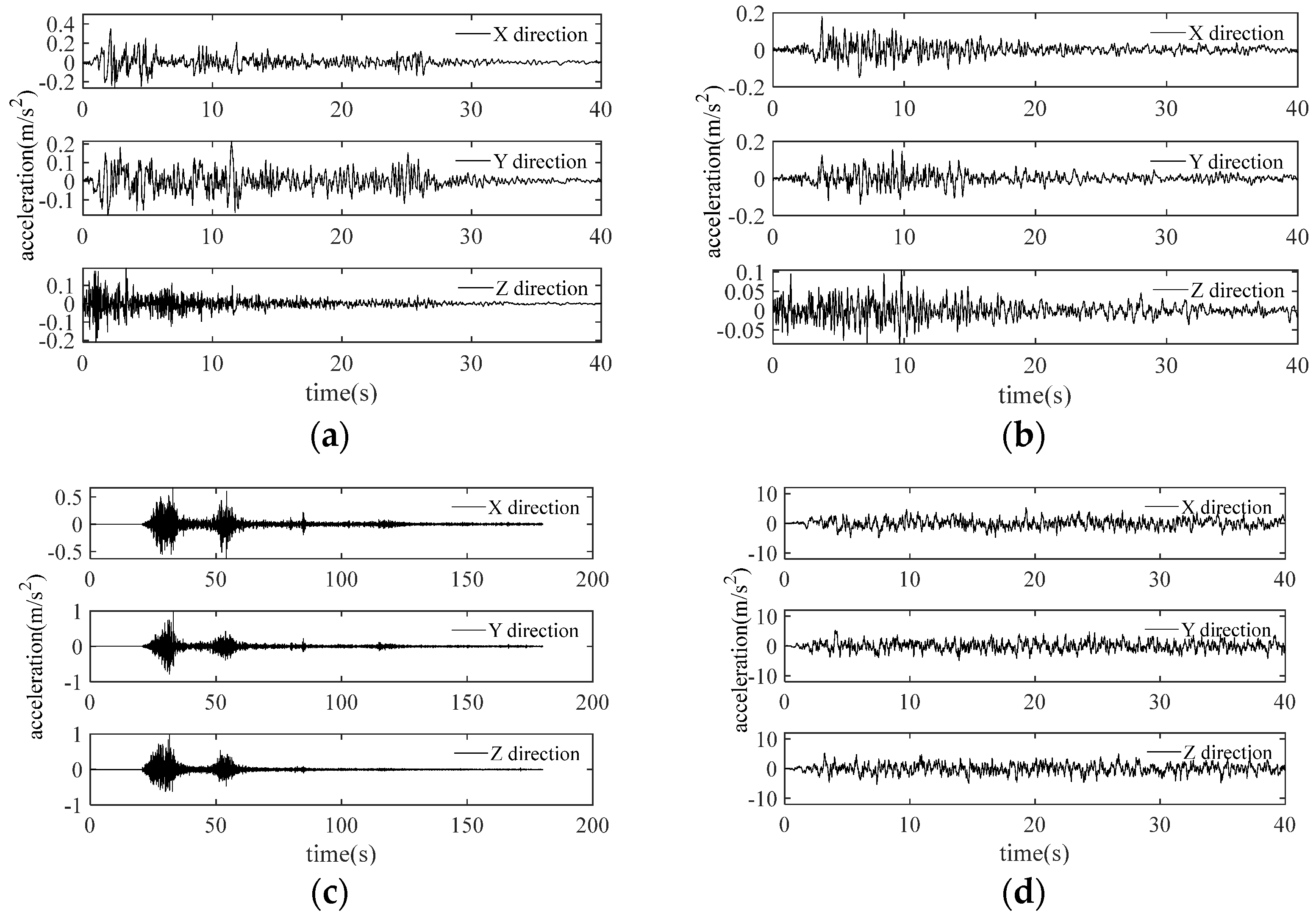
2.2. Seismic Wave Selection

Three natural seismic waves and one artificial seismic wave are selected as the input excitation of the shaking table. The natural seismic waves are El Centro wave, Taft wave and Wolong wave, respectively. The time history curve of the seismic wave is shown in Figure 3. The peak accelerations of seismic waves were adjusted to 0.1 g, 0.25 g, 0.5 g and 0.75 g, respectively.
Considering that the test model is scaled from a large LNG storage tank, when the ground motion is input to the shaking table, the time interval of the seismic wave should be compressed to 1/5 of the original seismic record.

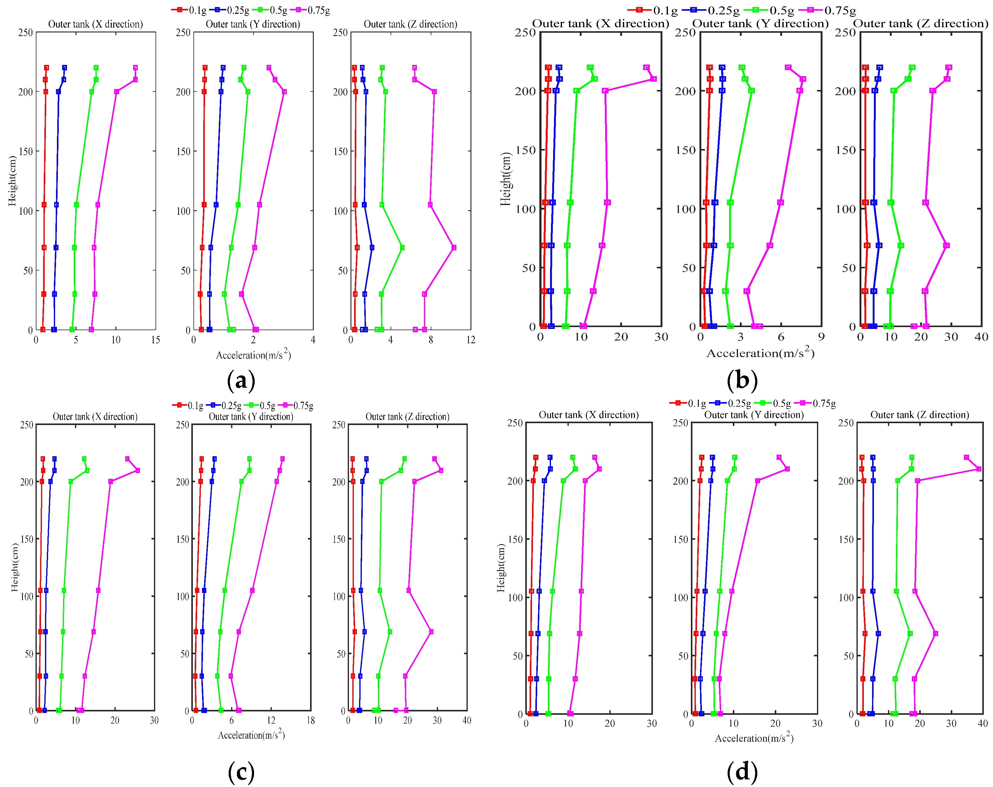
2.3. Analysis of Test Results

2.3.1. Non-Isolated Storage Tanks

Extracting the peak acceleration measured by the acceleration sensor and drawing the peak acceleration variation curve of the non-isolated storage tank, according to the test direction and height of the acceleration sensor, as shown in Figure 4.
As shown in Figure 4a, under the action of the seismic wave in the X direction, the Y and Z directions of the storage tank will still produce a certain acceleration response, but the magnitude of the acceleration response in the Y and Z directions is smaller than that in the X direction. As the height increases, the X direction acceleration of the non-isolated storage tank gradually increases. Since the dome is the weakest position, the acceleration at the top of the dome increases sharply, and the acceleration response reaches a peak at the top of the dome. The Y direction and Z direction acceleration responses decrease at the dome position. As the seismic peak acceleration increases, the Y direction acceleration at the top of the cap becomes more and more obvious, and the Z direction acceleration at the position of the center of mass of the storage tank is also more obvious. This phenomenon shows that the top structure of the storage tank cap has a higher strength and good stability, and the Z direction centroid position is the most unfavorable force position on the outer tank wall.
As shown in Figure 4b, under the action of the ground motion in the XZ direction, the Y direction of the storage tank will still produce a certain acceleration response, but it is smaller than the X and Z directions, and the Z direction acceleration response is more severe than the X direction. With the increase in the peak seismic acceleration, the acceleration responses in the X, Y and Z directions gradually increase along the height direction, but the acceleration in the Y direction decreases more and more at the top of the bearing platform, and the acceleration in the Z direction increases more and more at the position of the center of mass of the storage tank, and the acceleration at the top of the dome increases sharply, which is also consistent with the seismic response law of the storage tank under the action of the X direction ground motion.
As shown in Figure 4c,d, under the action of XYZ three-direction ground motion, the X direction acceleration of the outer tank of the storage tank gradually increases with the increase in height. The acceleration at the top of the dome increases sharply, but decreases when it reaches the top of the dome, and the greater the earthquake intensity, the more obvious the sudden change phenomenon, which is also consistent with the seismic response law of the storage tank under the action of X unidirectional and XZ bidirectional ground motions. The phenomenon also shows the weakness of the dome. When the seismic design of the storage tank is carried out, the position of the dome needs to be reinforced to prevent the damage of the entire LNG storage tank due to the weak dome in practical engineering applications.
On the whole, under the action of the X direction, XZ two-direction and XYZ three-direction ground motion, the acceleration response of the Z direction is more severe than that of the X and Y directions, indicating that the tank structure is excited by one-direction, two-direction and three-direction ground motion. When the storage tank is designed, it will have a large vertical (Z direction) acceleration response, and it is necessary to take vertical seismic isolation measures for the storage tank into consideration when designing the storage tank.
In order to study the variation law of the maximum displacement of the non-isolated dome under different loading conditions, the Wolong wave and artificial wave were selected for analysis, as shown in Table 3. Other seismic waves have the same effect on the dome of the non-isolated storage tank.
Comparing the test results of the Wolong wave (0.75 g) in the X direction, XZ direction and XYZ direction, it can be seen that under the Wolong wave (0.75 g, XYZ direction), the dome has the largest displacement in X and Y directions, and the displacement response in X direction is more obvious than that in Y direction. The displacements are 6.73 mm and 6.67 mm, respectively, which indicates that the displacement response of the tank model is larger with more excitation directions. Under the excitation of the Wolong wave (0.75 g) in the XZ direction, the maximum displacement of the dome in X is 6.16 mm. The maximum X displacement under Wolong wave (0.75 g, XYZ direction) is 1.09 times the displacement of that under Wolong wave (0.75 g, XZ direction). Under the excitation of the Wolong wave (0.75 g) in the X direction, the maximum displacement of the dome in X is 6.02 mm. The maximum X displacement under the Wolong wave (0.75 g, XYZ direction) is 1.12 times the displacement of that under the Wolong wave (0.75 g, X direction).
Comparing with different peak accelerations under the action of XYZ three-direction Wolong wave, as the peak acceleration increases, the maximum displacement of the dome also increases, reaching the maximum when the peak acceleration is 0.75 g, and the maximum displacement in the X direction is 6.73 mm. Under the excitation of the Wolong wave (0.10 g) in the XYZ direction, the maximum displacements of the dome in X and Y are 0.87 mm and 0.17 mm. The maximum X displacement under the Wolong wave (0.75 g, XYZ direction) is 7.74 times the displacement of that under the Wolong wave (0.10 g, XYZ direction), and the maximum Y displacement under the Wolong wave (0.75 g, XYZ direction) is 39.24 times the displacement of that under the Wolong wave (0.10 g, XYZ direction).
In comparison with different peak accelerations under the action of XYZ three-direction artificial wave, it can be seen that under the artificial wave (0.75 g, XYZ direction), the dome has the largest displacement in the X and Y directions, and the displacements are 31.04 mm and 48.07 mm, respectively. Different from the Wolong wave (0.75 g, XYZ direction), the Y direction displacement response of the artificial wave (0.75 g, XYZ direction) is more severe than the X direction. The maximum X displacement under artificial wave (0.75 g, XYZ direction) is 4.61 times the displacement of that under the Wolong wave (0.75 g, X direction). The maximum Y displacement under the artificial wave (0.75 g, XYZ direction) is 7.21 times the displacement of that under the Wolong wave (0.75 g, X direction).
In comparison with different peak accelerations under the action of XYZ three-direction artificial wave, as the peak acceleration increases, the maximum displacement of the dome also increases, reaching the maximum when the peak acceleration is 0.75 g, and the maximum displacement in the X direction is 31.04 mm. Under the excitation of the artificial wave (0.10 g) in the XYZ direction, the maximum displacements of the dome in X and Y are 3.80 mm and 6.23 mm. The maximum X displacement under the artificial wave (0.75 g, XYZ direction) is 8.17 times the displacement of that under the artificial wave (0.10 g, XYZ direction), and the maximum Y displacement under the artificial wave (0.75 g, XYZ direction) is 7.72 times the displacement of that under the artificial wave (0.10 g, XYZ direction).

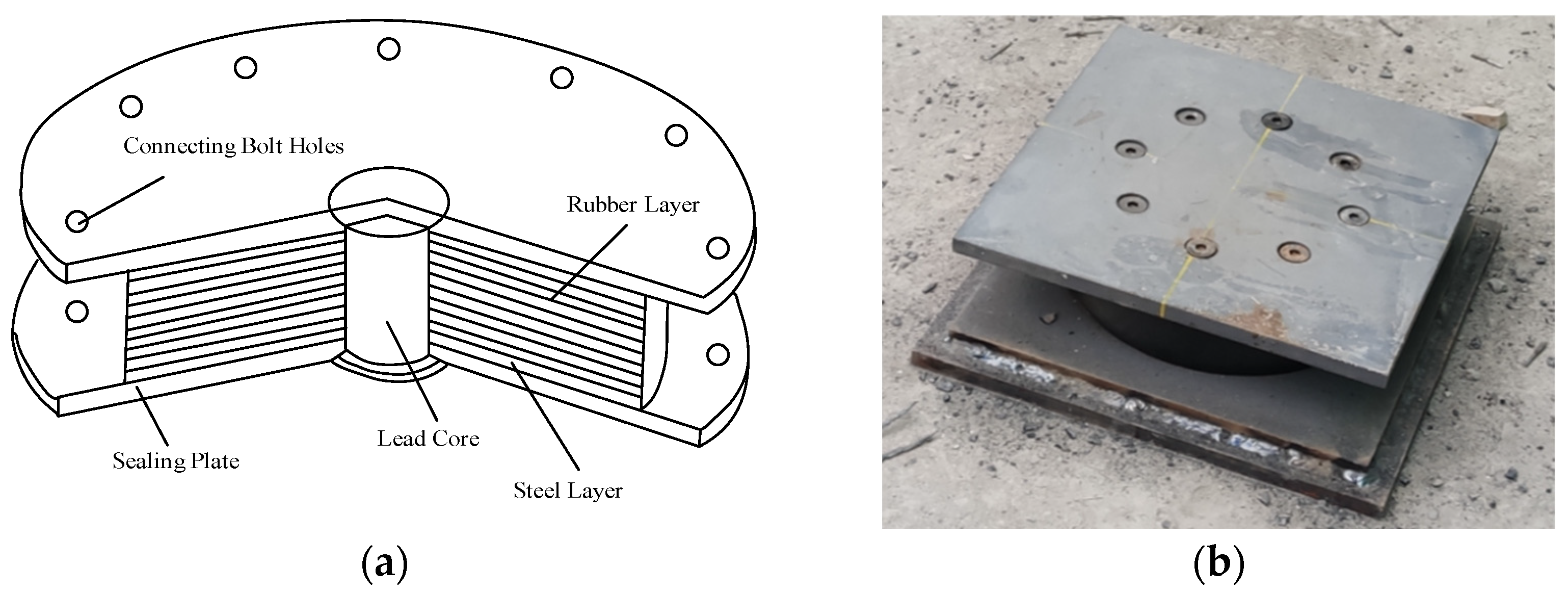
2.3.2. Isolated Storage Tank

In order to compare the effect of the isolation bearing, the acceleration responses of the non-isolated storage tank and the isolation storage tank are compared, as shown in Figure 5. Under the same seismic wave excitation, for the non-isolated storage tank, the acceleration response roughly shows a linear increasing trend, while for the isolated storage tank, the acceleration response first decreases with the increase in height, and when it reaches the middle of the tank wall, the acceleration response decreases. The acceleration response in turn increases with altitude. This is mainly due to the introduction of a soft horizontal layer (i.e., seismic isolation bearing) at the bottom of the storage tank, the energy dissipation of seismic waves through the horizontal layer, and the energy transmitted to the upper structure of the storage tank is attenuated.
The acceleration response of the concrete outer tank and the steel inner tank is significantly reduced after the isolation bearing is adopted. In different test directions, the vibration isolation bearings can reduce the acceleration response of the storage tank, and the reduction is more obvious in the loading direction. With the increase in the height of the acceleration measuring point, the seismic isolation effect is more obvious.
The displacement of the tank becomes larger due to the introduction of a soft horizontal layer at the bottom of the tank. From three different loading modes (X direction, XZ direction, XYZ direction), different peak accelerations and different seismic waveforms, the maximum displacement responses of the dome top of the isolated storage tank and the non-isolated storage tank were compared. The calculation formula of the amplification factor is:
a m p l i f i c a t i o n   f a c t o r = ( u i s o u n o n i s o ) / u n o n i s o
where u i s o is the displacement of the isolation tank and u n o n i s o is the displacement of the non-isolation tank.
It can be seen from Table 4 that after the isolation bearing is used, the displacement of the storage tank will be amplified to a certain extent.

3. Simplified Mechanical Model of the Storage Tank

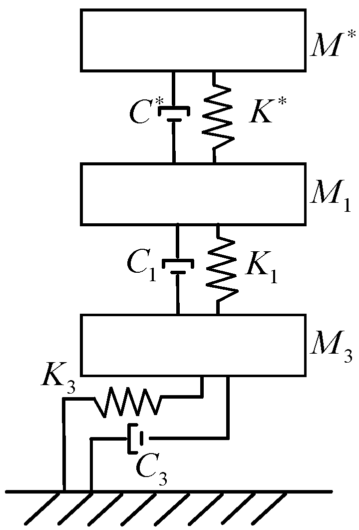
3.1. Comparison of Simplified Models with Different Degrees of Freedom

Zhang et al. [8] regard the concrete outer tank as a single-degree-of-freedom (1-DOF) model and deduce the motion theory of the outer tank. This paper refers to its research method to study the dynamic response characteristics of concrete outer tank under earthquake action. Taking a non-isolated storage tank as an example, it is simplified into single-degree-of-freedom, two-degree-of-freedom (2-DOF), three-degree-of-freedom (3-DOF) and four-degree-of-freedom (4-DOF) models, respectively, and the corresponding motion equations are established. By comparing the theoretical calculation results of the four simplified models with the shaking table test results, it is determined which simplified model can more comprehensively characterize the dynamic response characteristics of the outer tank.
In order to compare the calculation effects of different models, the Wolong wave (X direction, 0.75 g) was selected for analysis and the acceleration time history curve of the dome was compared. Figure 6 shows a comparison of the results of different simplified models and shaking table tests. It can be seen from the figure that the calculation results of the 2-DOF model fit the results of the shaking table test the worst. The model’s calculations amplify the seismic response of the tank. Only the calculation results of the 1-DOF model and the 3-DOF model are in good agreement with the results of the shaking table test.
Table 5 is a comparison table of the acceleration amplitude fitting of different simplified models. The fitting degrees of the 1-DOF, 2-DOF, 3-DOF and 4-DOF models are 81.24%, 46.72%, 83.46% and 79.87%, respectively. The theoretical results of the 3-DOF model are the closest to the experimental results, which indicates that the 3-DOF model can better reflect the dynamic response characteristics of non-isolated storage tanks. In the following, the seismic response of the storage tank will be analyzed based on the 3-DOF model.

3.2. Equations of Motion for Non-Isolated Storage Tank

Considering the mass and stiffness distribution characteristics of the outer tank, the non-isolated storage tank is simplified as a 3-DOF model. Among them, the mass and height of the dome are M * and h * . The equivalent mass and equivalent height of the outer tank wall are M 1 and h 1 , respectively. The mass and height of the platform are M 2 and h 2 , respectively. The simplified model of the non-isolated storage tank is shown in Figure 7.
Assuming that the uniform mass of the outer tank wall along the height direction is m , lateral displacement is x ( z , t ) , which is:
x ( z , t ) = sin ( π z 2 h ) sin ( ω t )  
Under the excitation of horizontal load, according to the principle of equivalent base shear force and overturning moment, Equations (3) and (4) can be obtained. The equivalent mass and equivalent height of the outer tank wall particle can be obtained by combining the two equations:
0 h m sin ( π z 2 h ) d z × ω 2 sin ( ω t ) = M 1 sin ( π h 1 2 h ) × ω 2 sin ( ω t )
0 h m sin ( π z 2 h ) z d z × ω 2 sin ( ω t ) = M 1 sin ( π h 1 2 h ) h 1 × ω 2 sin ( ω t )
The outer tank wall is regarded as a shear wall with an annular section, and the stiffness of the outer tank wall is calculated according to the calculation method of the equivalent stiffness of the shear wall with small openings Equation (5) is the calculation formula for the lateral displacement of the shear wall under the action of the concentrated force P , and the stiffness K 1 of the outer tank wall is the reciprocal of the lateral displacement under the action of the unit concentration force:
u = 1.2 × P h 3 3 E I ( 1 + 3 μ E I G A h 2 )
In the formula, E I is the bending stiffness, G A is the shear stiffness, μ is the shear non-uniformity coefficient, and h is the height of the wall.
The engineering frequency of the concrete outer tank can be obtained by the approximate method [8], as shown in Formula (6):
1 f o t 2 = 1 f F 2 + 1 f S 2 + 1 f R 2 + ( 1 f c F 2 + 1 f c S 2 )
In the formula, f F is the engineering frequency for the curved cantilever beam; f S is the engineering frequency of the shear cantilever beam; f R is the engineering frequency of the cantilever beam assumed based on a series of independent rings; f c F is the engineering frequency of a bent cantilever beam with lumped mass at the rod end; and f c S is the engineering frequency for a sheared cantilever beam with lumped mass at the rod ends. The above frequencies are calculated by Equations (7)–(13).
f F = 0.20 D c L 2 E c ρ c
f s = 1 8 L 1 + υ c E c ρ c
f R = 1 D c π 1 υ c 2 E c ρ c
f c F = 1 2 π k c F m d
k c F = 3 π E c ( D c 2 L ) 3 t c
f c S = 1 2 π k c S m d
k c F = π 4 ( 1 + υ c ) D c 2 L E c t c
In Equations (7)–(13), D c is the diameter of the outer tank. L is the height of the outer tank wall. E c , ρ c and υ c are the elastic modulus, Poisson’s ratio and density of concrete, respectively. m d is the mass of the dome. t c is the thickness of the outer tank wall.
The overall stiffness and circular frequency of the outer tank can be calculated using Equations (14) and (15).
ω = 2 π f o t
k = 4 π 2 f o t 2 M
According to the principle of spring series to calculate the stiffness, the stiffness of the dome can be calculated from the overall stiffness of the outer tank and the stiffness of the outer tank side wall.
k = k 1 k 2 k 1 + k 2
According to D’Alembert’s principle, the mass matrix and stiffness matrix of the non-isolated storage tank can be obtained as:
M = [ M * 0 0 0 M 1 0 0 0 M 2 ] K = [ K * K * 0 K * K * + K 1 K 1 0 K 1 K 1 + K 3 ]
The damping matrix of the tank can be obtained by Rayleigh damping:
C = a 0 M + a 1 K
Therefore, the equation of motion of the outer tank under the action of earthquake can be obtained as:
M { x ¨ * ( t ) x ¨ 1 ( t ) x ¨ 2 ( t ) } + C { x ˙ * ( t ) x ˙ 1 ( t ) x ˙ 2 ( t ) } + K { x * ( t ) x 1 ( t ) x 2 ( t ) } = x ¨ g ( t ) { M * M 1 M 2 }
For non-isolated storage tanks, the load column vector is F ( t ) = { M * , M 1 , M 2 } T and the displacement column vector is { x ( t ) } = { x * ( t ) , x 1 ( t ) , x 2 ( t ) } T .

3.3. Equation of Motion of the Isolated Storage Tank

Considering the large difference between the horizontal stiffness of the isolation bearing and the lateral stiffness of the pile foundation, the pile foundation is not considered when establishing the model of the isolation storage tank, and the isolation storage tank is simplified as a three-degree-of-freedom model. Among them, the mass and height of the dome are M * and h * , respectively. The equivalent mass and equivalent height of the outer tank wall are M 1 and h 1 , respectively. The mass and height of the platform are M 3 and h 3 , respectively. The simplified model of the isolated storage tank is shown in Figure 8.
The mass matrix and stiffness matrix of the seismic isolation storage tank are:
M = [ M * 0 0 0 M 1 0 0 0 M 3 ] K = [ K * K * 0 K * K * + K 1 K 1 0 K 1 K 1 + K 3 ]
Let the displacement of the outer tank be x * ( t ) , the displacement of the bearing platform be x 1 ( t ) and the displacement of the pile foundation be x 2 ( t ) . According to the Hamilton principle of structural dynamics, the motion control equation is obtained as:
M { x ¨ * ( t ) x ¨ 1 ( t ) x ¨ 2 ( t ) } + C { x ˙ * ( t ) x ˙ 1 ( t ) x ˙ 2 ( t ) } + K { x * ( t ) x 1 ( t ) x 2 ( t ) } = x ¨ g ( t ) { M * M 1 M 3 }

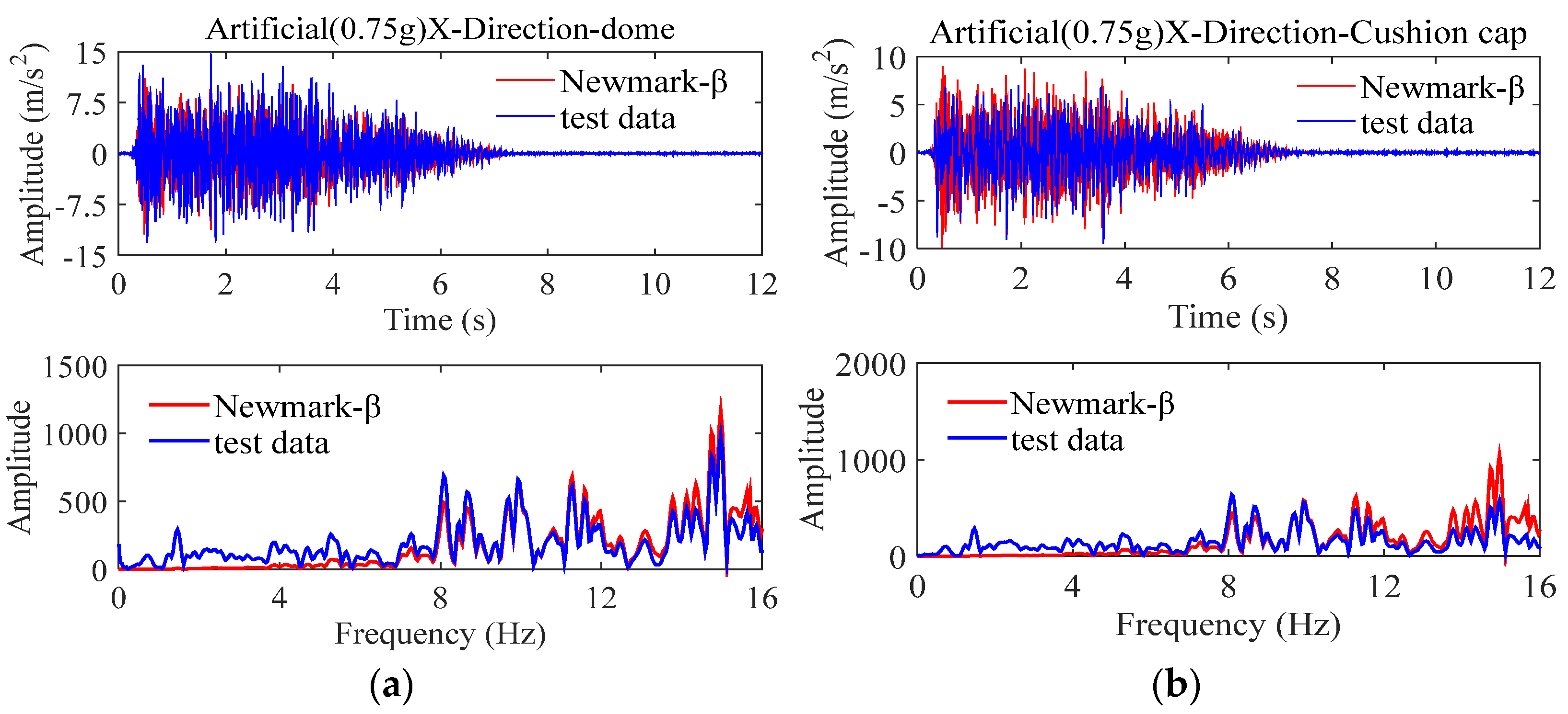
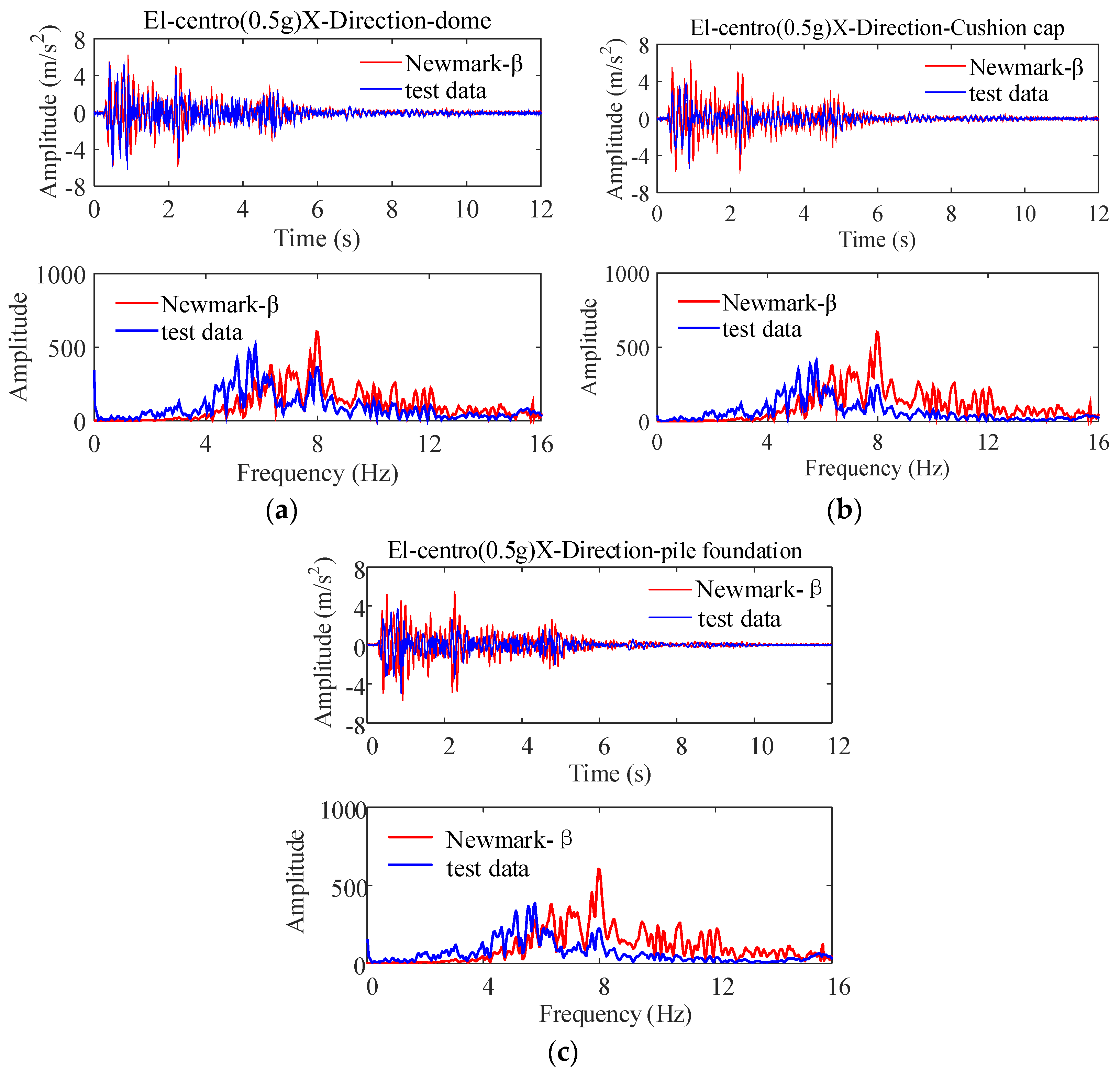
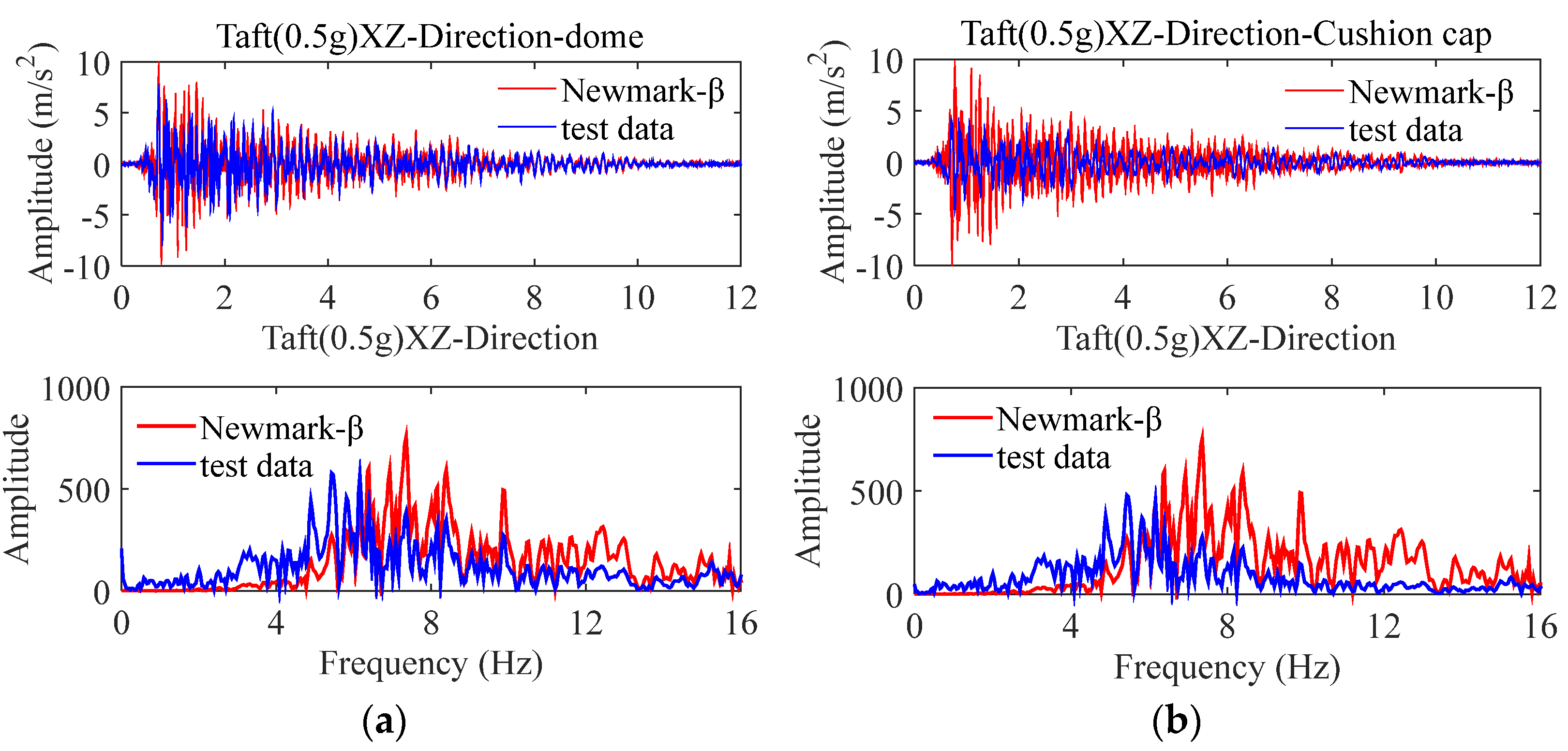
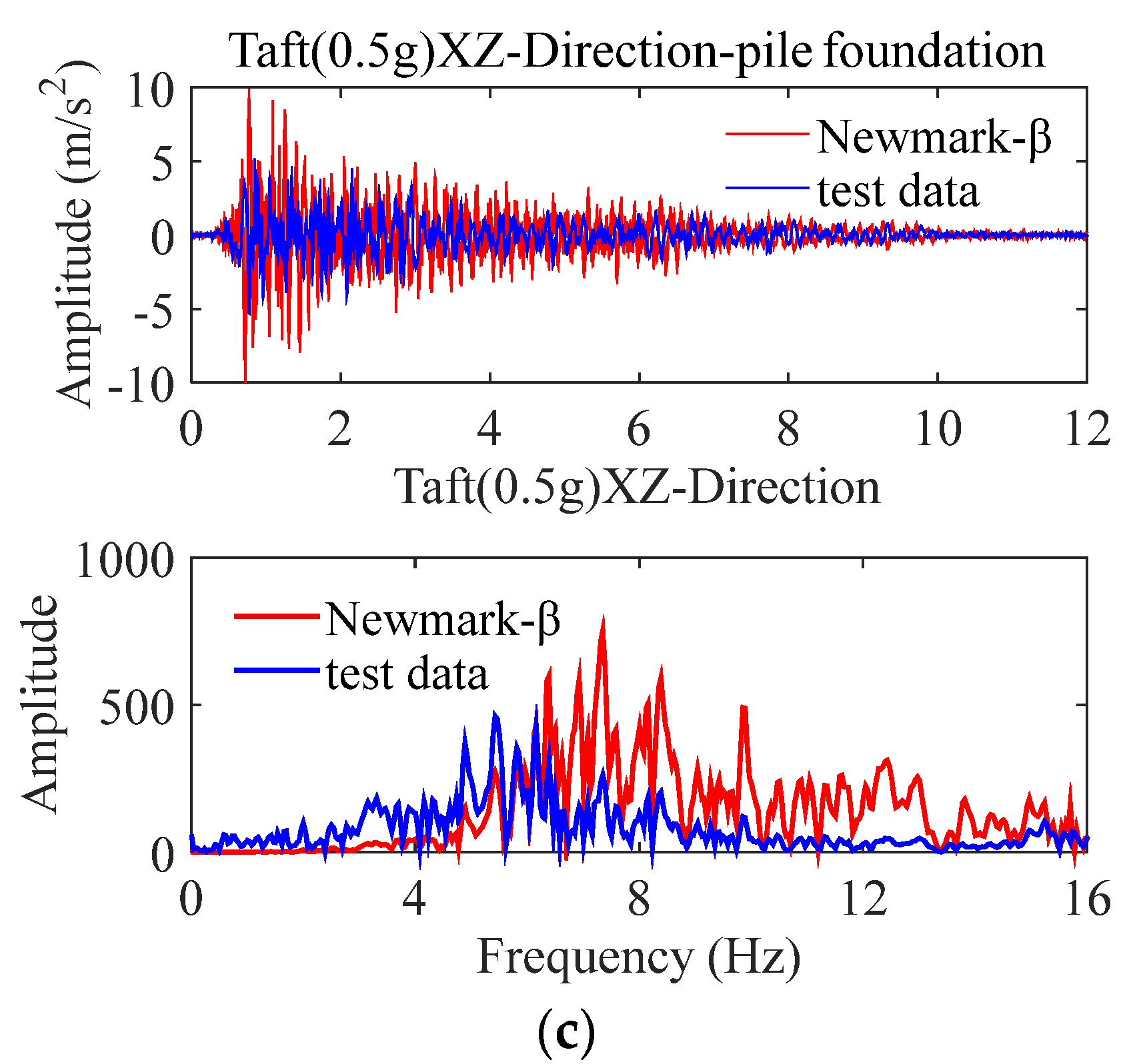
4. Comparative Analysis of Results

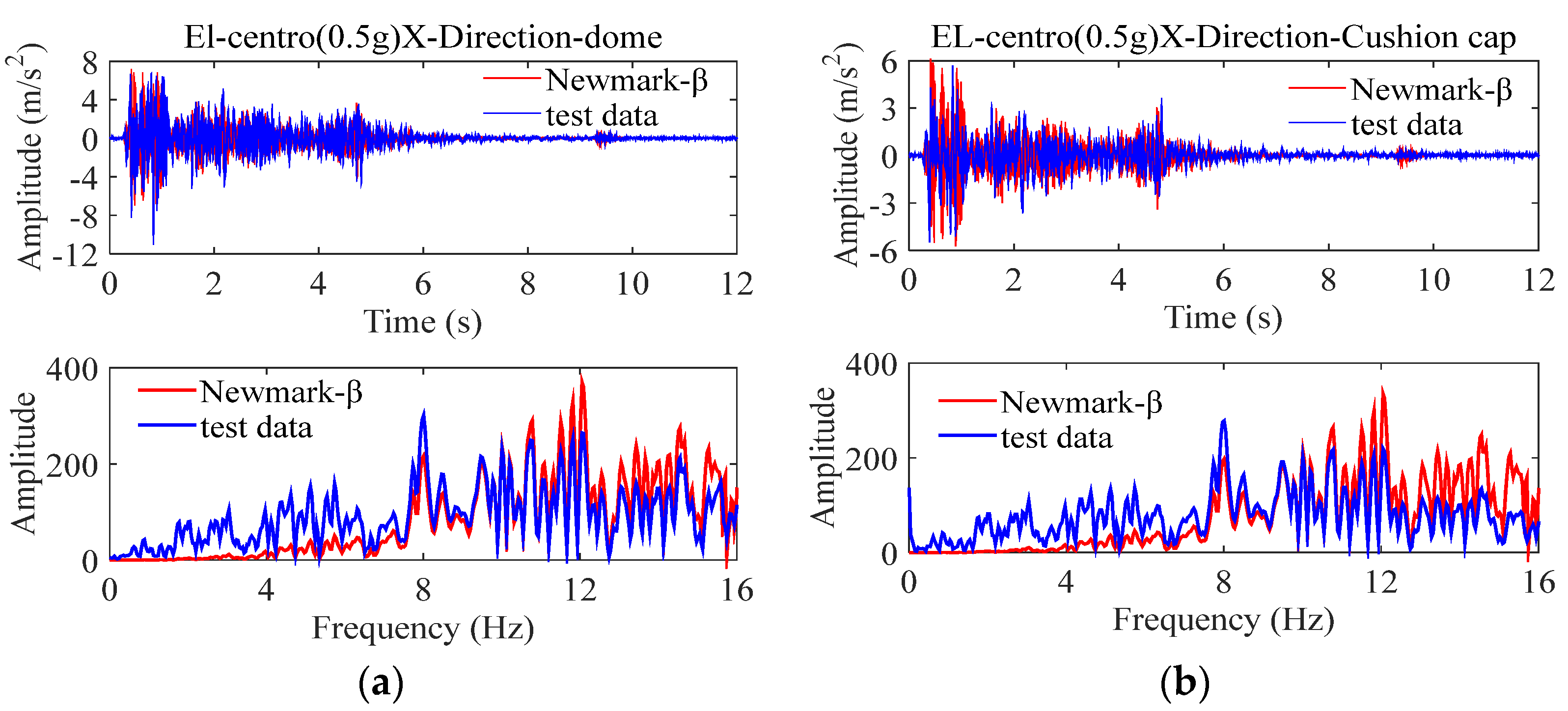
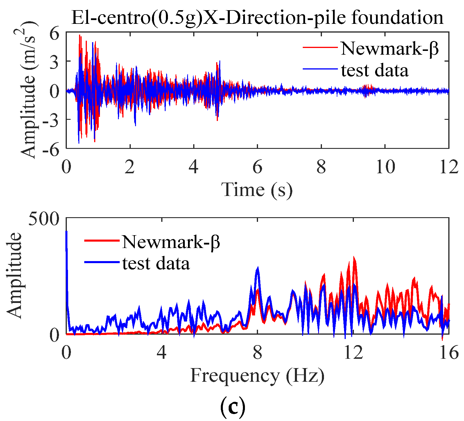
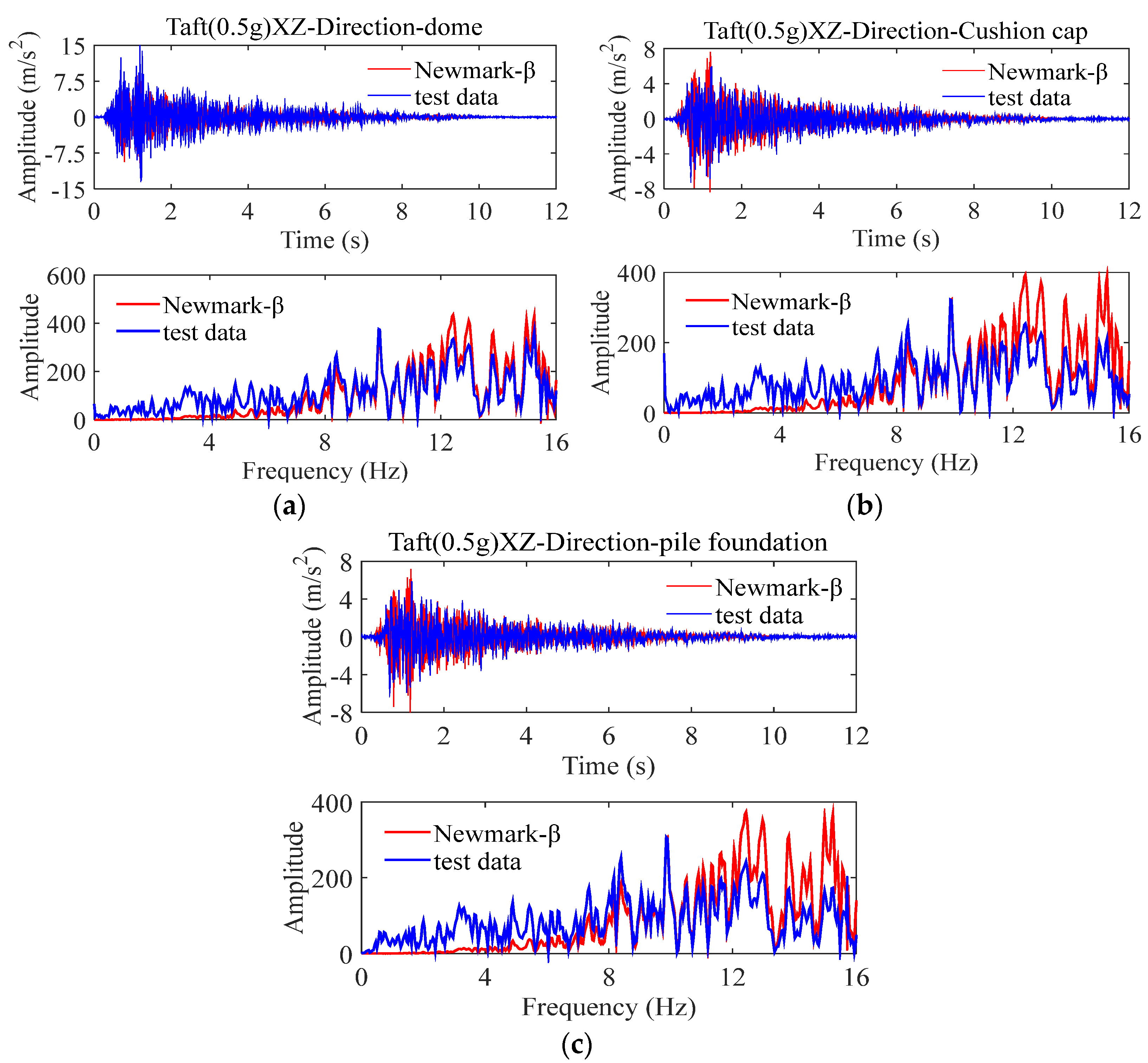
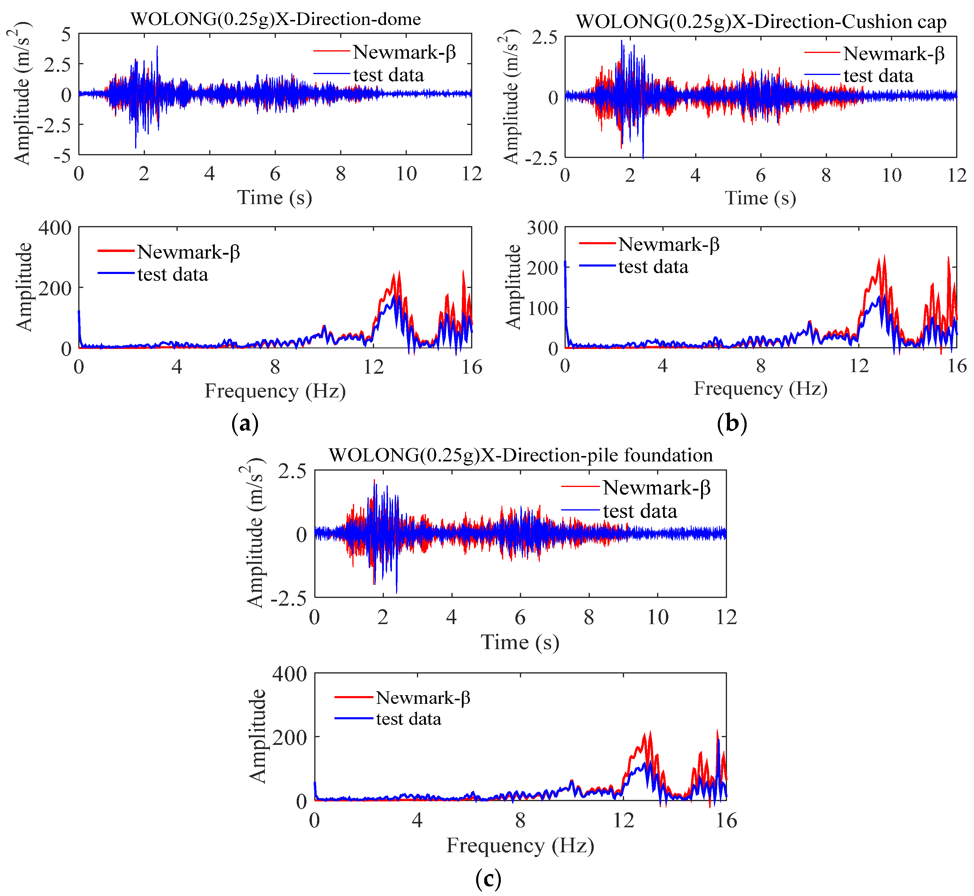
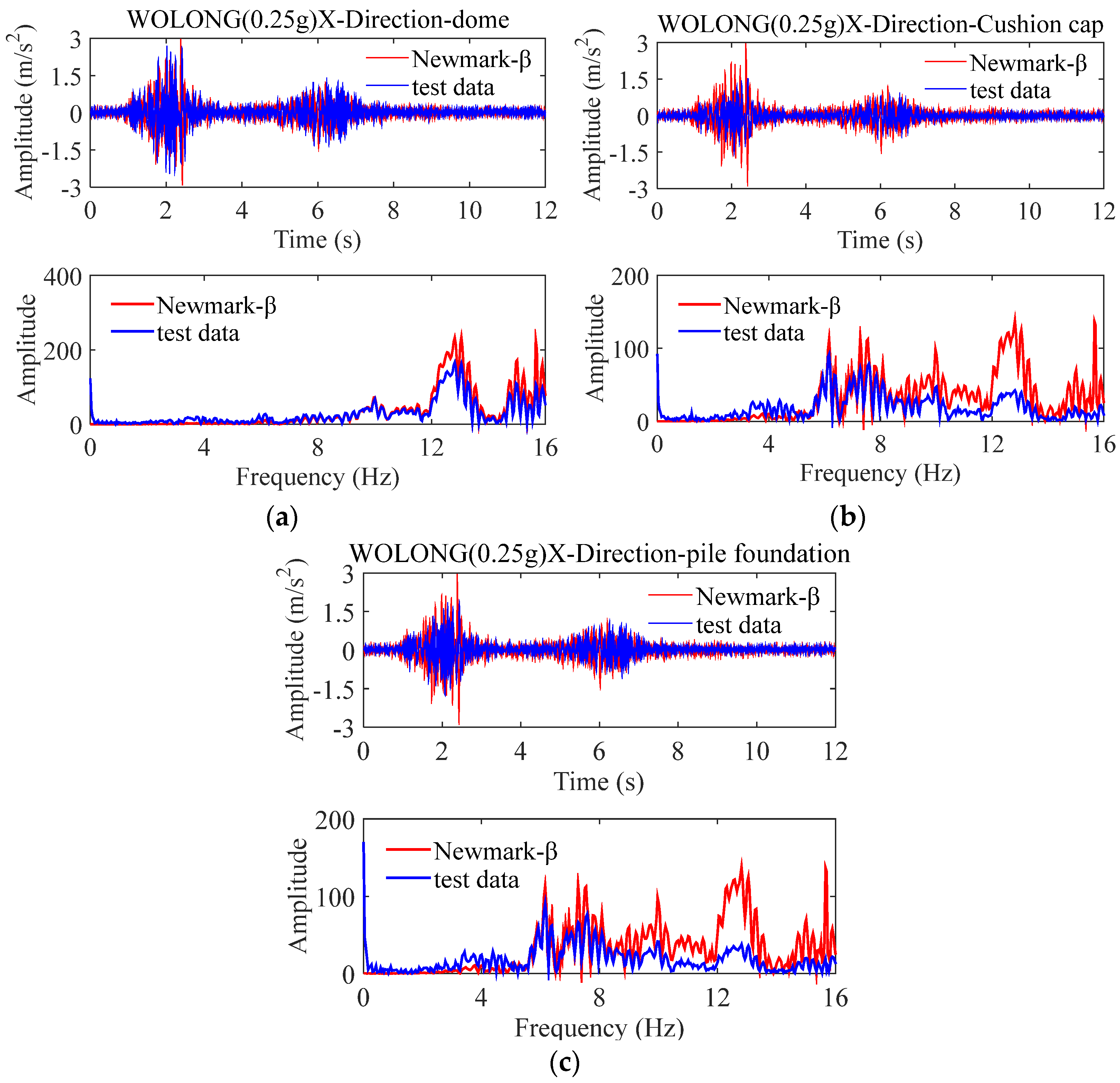
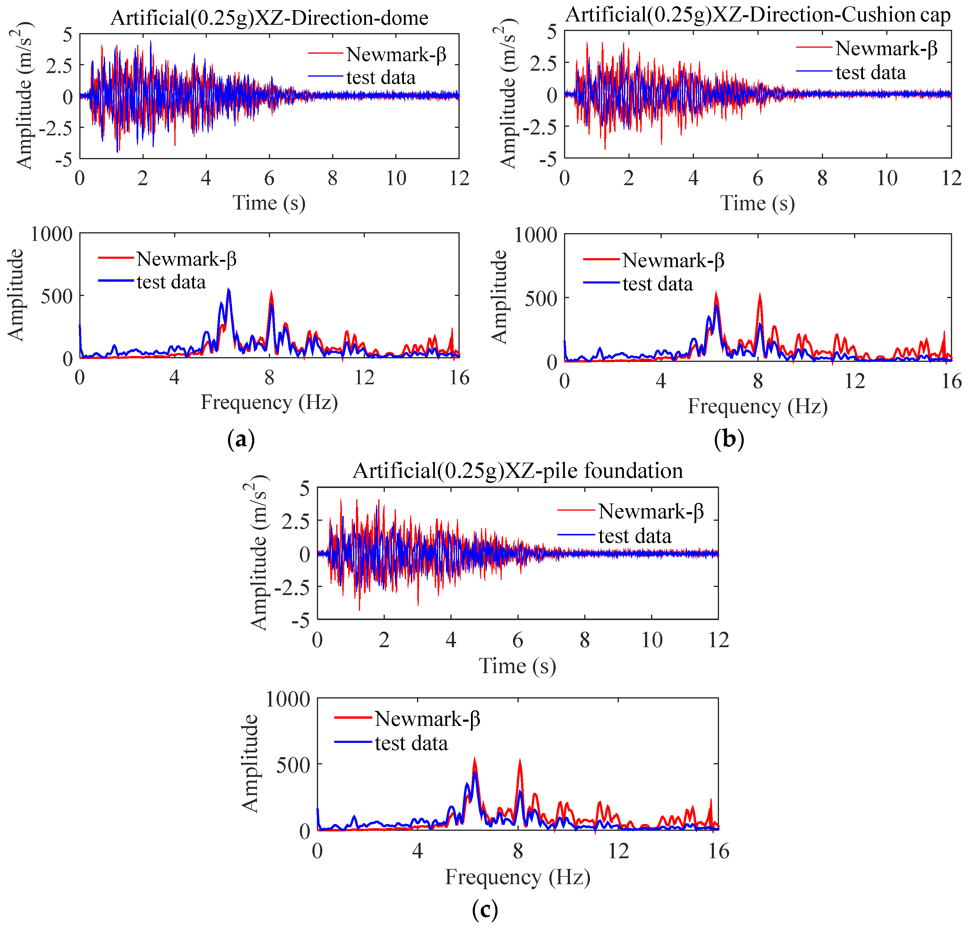
4.1. Non-Isolated Storage Tank

Through the Newmark-β method, the parameter matrix of the structure is brought into the motion control equation and the theoretical solution of the storage tank model is finally obtained. Four different seismic waves are selected, respectively, which are the El Centro wave with the peak acceleration of X unidirectional loading of 0.5 g, X unidirectional loading Wolong wave with peak acceleration of 0.25 g, XZ bidirectional loading of Taft wave with peak acceleration of 0.5 g and X unidirectional loading of artificial wave with peak acceleration of 0.75 g. Figure 9, Figure 10, Figure 11 and Figure 12 will show the comparison between the theoretical solution and the experimental data (Newmark-β in the figure is the theoretical solution and the test data are the experimental data).
The seismic acceleration response time history shows that compared with the pile foundation and the cap, the acceleration response of the dome is the most severe, and the acceleration time history of the pile foundation, the cap and the dome is only different in amplitude, but the waveform does not change significantly.
It can be seen from the spectrogram that under the excitation of El Centro wave, the tank dome, pile foundation and cap all produce the maximum acceleration response when the frequency is 8 Hz. Under the excitation of Taft wave, the tank produces the maximum acceleration response at 9.5 Hz. Under the Wolong wave excitation, the storage tank produces the maximum acceleration response at 13 Hz. Under the artificial wave excitation, the storage tank produces the maximum acceleration response at 8 Hz.
Through the acceleration time history curve and frequency spectrum curve, comparing the experimental data and theoretical solutions of four kinds of seismic wave shaking table, it is shown that under different seismic wave excitation, a three-degree-of-freedom simplified model is established to obtain the storage tank dome, cap and pile foundation through the Newmark-β method. The theoretical solution and the actual shaking table test data have a high degree of fitting, which fully reflects the effectiveness and wide application range of this method, which can be extended to practical engineering applications.

4.2. Isolated Storage Tank

Through the Newmark-β method, the parameter matrix of the structure is brought into the motion control equation and the theoretical solution of the isolated storage tank model is finally obtained, with four different seismic waves selected, El Centro wave, X one-direction loading Wolong wave with peak acceleration of 0.25 g, XZ two-direction loading Taft wave with peak acceleration of 0.5 g and XZ two-direction loading artificial wave with peak acceleration of 0.25 g, respectively. Figure 13, Figure 14, Figure 15 and Figure 16 show seismic isolation under different working conditions and compare the experimental data of the storage tank with the theoretical solution (Newmark-β in the figure is the theoretical solution and the test data is the experimental data).
By comparing the seismic acceleration response time history obtained from the shaking table test and theoretical analysis of the isolated storage tank, the following conclusions can be drawn:
(1) Compared with the pile foundation and the cap, the acceleration response of the dome is the most severe, and the acceleration time history of the pile foundation, the cap and the dome is only different in amplitude, but the waveform does not change significantly. This phenomenon is the same as the seismic response law of non-isolated storage tanks.
(2) It can be seen from the spectrogram that under the excitation of the El Centro wave, Taft wave and artificial wave, the isolated storage tank dome, pile foundation and bearing platform all produce the maximum acceleration response when the frequency is 6 Hz. Under the excitation of the Wolong wave, the storage tank produces the maximum acceleration response at 13 Hz. Compared with the non-isolated storage tank, the frequency of the maximum acceleration response of the seismically isolated storage tank is lower, indicating that the isolation bearing can effectively increase the characteristic period of the storage tank and reduce the resonance effect of the seismic wave, thereby eliminating the energy of the seismic wave and finally ensuring the isolation. Safe operation of seismic storage tanks under the action of earthquakes.
(3) Through the acceleration time history curve and the frequency spectrum curve, the test data and the theoretical solution of the vibration-isolated storage tank under the excitation of four kinds of seismic waves are compared, and the four kinds of seismic waves have a good fitting effect, which also shows that this method is applicable and that it can be widely used in different seismic conditions. It can also provide a theoretical basis for improving the theory of isolation of storage tanks and optimizing the isolation design of storage tanks.

5. Conclusions

Based on the research of existing scholars, this paper proposes to simplify the LNG storage tank into a three-degree-of-freedom mechanical model including dome, tank wall and bearing platform, establish the motion control equation of the LNG storage tank system, input the seismic excitation, and obtain it by the Newmark-β method. The main conclusions of the seismic response of the storage tank structure are as follows:
(1) Through the shaking table test, the theoretical research on the earthquake resistance of the concrete outer tank under the action of one-direction, two-direction and three-direction ground motion is carried out. The acceleration response at the top is small and the acceleration response at the position of the dome is relatively large, which further concludes that in the process of seismic design of the storage tank structure, the strength of the dome part of the storage tank needs to be increased, and the vertical parts of the storage tank need to be strengthened.
(2) For the non-isolated storage tank, the acceleration response generally shows a linear increasing trend, while for the isolated storage tank, the acceleration response first decreases with the increase in height, and when it reaches the middle of the tank wall, the acceleration response increases as the height increases.
(3) By comparing the theoretical solution of the simplified mechanical model of various storage tanks with the test data of the shaking table, it is concluded that the three-degree-of-freedom model of the storage tank simplified as a dome, a cap and a pile foundation has the best fitting effect. The real response under the action of ground motion provides new technical means.
(4) By comparing the four kinds of seismic wave shaking table test data and theoretical solutions, the theoretical solutions of the tank dome, the cap and the pile foundation have a high degree of fitting with the actual shaking table test data, which fully reflects the effectiveness of this method. It has a wide range of performance and application and provides a theoretical basis for optimizing the seismic design of storage tanks.

Author Contributions

Writing—original draft, Z.C.; Methodology, L.Z. and J.F.; Writing—review and editing, Z.X.; Visualization, Y.L. and H.C.; Data curation, X.X. All authors have read and agreed to the published version of the manuscript.

Funding

The authors appreciate the testing facility as well as the technical assistance provided by the CLP Power Wind/Wave Tunnel Facility at the Hong Kong University of Science and Technology. The work is funded by the Key Laboratory of Icing and Anti/De-icing of CARDC (Grant No. IADL 20200304), the National Natural Science Foundation of China (Grant No.: 51908090), the Fundamental Research Funds for the Central Universities (Project No.: 2021CDJQY-001, 2022CDJXY-016), the Natural Science Foundation of Chongqing, China (cstc2020jcyj-msxmX0921), the Key Project of Technological Innovation and Application Development in Chongqing (Grant No.: cstc2019jscx-gksbX0017) and the Key Project of Science and Technology Research Program of Chongqing Municipal Education Commission (KJCXZD2020010).

Institutional Review Board Statement

Not applicable.

Informed Consent Statement

Not applicable.

Data Availability Statement

No data were reported in this study.

Acknowledgments

The authors would like to thank the anonymous reviewers for their valuable comments on the manuscript.

Conflicts of Interest

The authors declare no conflict of interest.

References

  1. Housner, G.W. Dynamic pressures on accelerated fluid containers. Bull. Seismol. Soc. Am. 1957, 47, 15–35. [Google Scholar] [CrossRef]
  2. Haroun, M.A.; Housner, G.W. Earthquake Response of Deformable Liquid Storage Tanks. J. Appl. Mech. 1981, 48, 411–418. [Google Scholar] [CrossRef]
  3. Veletsos, A.S.; Tang, Y.; Tang, H.T. Dynamic Response of Flexibly Supported Liquid-Storage Tanks. J. Struct. Eng. 1992, 118, 264–283. [Google Scholar] [CrossRef]
  4. Veletsos, A.S.; Tang, Y. Dynamics of Vertically Excited Liquid Storage Tanks. J. Struct. Eng. 1986, 112, 1228–1246. [Google Scholar] [CrossRef]
  5. Malhotra, P.K.; Wenk, T.; Wieland, M. Simple Procedure for Seismic Analysis of Liquid-Storage Tanks. Struct. Eng. Int. 2000, 10, 197–201. [Google Scholar] [CrossRef] [Green Version]
  6. Shrimali, M.K.; Jangid, R.S. Seismic response of liquid storage tanks isolated by sliding bearings. Eng. Struct. 2002, 24, 909–921. [Google Scholar] [CrossRef]
  7. Shrimali, M.K.; Jangid, R.S. Seismic analysis of base-isolated liquid storage tanks. J. Sound Vib. 2004, 275, 59–75. [Google Scholar] [CrossRef]
  8. Zhang, R.; Weng, D.; Ren, X. Seismic analysis of a LNG storage tank isolated by a multiple friction pendulum system. Earthq. Eng. Eng. Vib. 2011, 10, 253–262. [Google Scholar] [CrossRef]
  9. Zhang, R.; Zhao, Z.; Pan, C. Influence of mechanical layout of inerter systems on seismic mitigation of storage tanks. Soil Dyn. Earthq. Eng. 2018, 114, 639–649. [Google Scholar] [CrossRef]
  10. Ruifu, Z.; Zhipeng, Z.; Xuchuan, L.; Lingxin, Z. Optimal design of inerter systems for the force-transmission suppression of oscillating structures. Earthq. Eng. Eng. Vib. 2022, 21, 441–454. [Google Scholar] [CrossRef]
  11. Zhao, Z.; Chen, Q.; Zhang, R.; Pan, C.; Jiang, Y. Energy dissipation mechanism of inerter systems. Int. J. Mech. Sci. 2020, 184, 105845. [Google Scholar] [CrossRef]
  12. Jiang, Y.; Zhao, Z.; Zhang, R.; De Domenico, D.; Pan, C. Optimal design based on analytical solution for storage tank with inerter isolation system. Soil Dyn. Earthq. Eng. 2020, 129, 105924. [Google Scholar] [CrossRef]
  13. Lin, S.; Wang, J.; Gao, S.; Zhao, H. Real-time hybrid test of a LNG storage tank with a variable curvature friction pendulum system. Arch. Civ. Mech. Eng. 2021, 21, 90. [Google Scholar] [CrossRef]
  14. Christovasilis, I.P.; Whittaker, A.S. Seismic Analysis of Conventional and Isolated LNG Tanks Using Mechanical Analogs. Earthq. Spectra 2008, 24, 599–616. [Google Scholar] [CrossRef]
  15. Rawat, A.; Matsagar, V.A.; Nagpal, A.K. Numerical study of base-isolated cylindrical liquid storage tanks using coupled acoustic-structural approach. Soil Dyn. Earthq. Eng. 2019, 119, 196–219. [Google Scholar] [CrossRef]
  16. Moslemi, M.; Kianoush, M.R. Parametric study on dynamic behavior of cylindrical ground-supported tanks. Eng. Struct. 2012, 42, 214–230. [Google Scholar] [CrossRef]
  17. Panchal, V.R.; Jangid, R.S. Seismic response of liquid storage steel tanks with variable frequency pendulum isolator. KSCE J. Civ. Eng. 2011, 15, 1041–1055. [Google Scholar] [CrossRef]
  18. Luo, D.; Liu, C.; Sun, J.; Cui, L.; Wang, Z. Liquefied natural gas storage tank simplified mechanical model and seismic response analysis. Soil Dyn. Earthq. Eng. 2021, 141, 106491. [Google Scholar] [CrossRef]
  19. Luo, D.; Sun, J.; Liu, C.; Cui, L.; Wang, Z. Damping Effect of Insulation on a Liquefied Natural Gas Tank Based on Shaking Table Tests. J. Earthq. Eng. 2022, 26, 2846–2866. [Google Scholar] [CrossRef]
  20. Cheng, X.; Luo, B.; Chen, J. Seismic Response considering LSI for Steel Rectangular Water Purification Structures. KSCE J. Civ. Eng. 2021, 25, 4261–4273. [Google Scholar] [CrossRef]
  21. Cheng, X.; Jing, W.; Gong, L. Simplified Model and Energy Dissipation Characteristics of a Rectangular Liquid-Storage Structure Controlled with Sliding Base Isolation and Displacement-Limiting Devices. J. Perform. Constr. Facil. 2017, 31, 04017071. [Google Scholar] [CrossRef]
  22. Scislo, L.; Guinchard, M. Non-invasive measurements of ultra-lightweight composite materials using Laser Doppler Vibrometry system. In Proceedings of the 26th International Congress on Sound and Vibration, Montreal, QC, Canada, 7–11 July 2019. [Google Scholar]
Figure 1. Dimensions of the test tank model: (a) Non-isolated storage tank; (b) Isolation storage tank.
Applsci 12 07663 g001
Figure 2. Dimensions of the test tank model: (a) Model diagram of lead-core vibration isolation rubber bearing; (b) Physical map of lead rubber bearing.
Applsci 12 07663 g002
Figure 3. Time−history curve of the seismic wave: (a) El Centro wave; (b) Taft wave; (c) Wolong wave; (d) Artificial wave.
Applsci 12 07663 g003
Figure 4. Variation law of acceleration response of non-isolated storage tank along height direction: (a) Wolong wave (X direction); (b) Wolong wave (XZ direction); (c) Wolong wave (XYZ direction); (d) Artificial wave (XYZ direction).
Applsci 12 07663 g004
Figure 5. Comparison of acceleration response of non-isolated and isolated tanks: (a) Wolong wave (XZ directions, 0.25 g); (b) Wolong wave (XYZ directions, 0.25 g); (c) Wolong wave (X direction, 0.5 g); (d) Wolong wave (XZ directions, 0.75 g).
Applsci 12 07663 g005
Figure 6. Comparison of theoretical solutions of four simplified models and shaking table test results: (a) Acceleration time history comparison of 1−DOF; (b) Acceleration time history comparison of 2−DOF; (c) Acceleration time history comparison of 3−DOF; (d) Acceleration time history comparison of 4−DOF.
Applsci 12 07663 g006
Figure 7. Simplified mechanical model of the storage tank.
Applsci 12 07663 g007
Figure 8. Simplified mechanical model of the isolation storage tank.
Applsci 12 07663 g008
Figure 9. Comparison of shaking table test data and theoretical solution under the El−Centro wave: (a) dome acceleration time history and spectrum comparison; (b) cushion cap acceleration time history and spectrum comparison; (c) pile foundation acceleration time history and spectrum comparison.
Applsci 12 07663 g009aApplsci 12 07663 g009b
Figure 10. Comparison of shaking table test data and theoretical solution under the Taft wave: (a) dome acceleration time history and spectrum comparison; (b) cushion cap acceleration time history and spectrum comparison; (c) pile foundation acceleration time history and spectrum comparison.
Applsci 12 07663 g010
Figure 11. Comparison of shaking table test data and theoretical solution under the Wolong wave: (a) dome acceleration time history and spectrum comparison; (b) cushion cap acceleration time history and spectrum comparison; (c) pile foundation acceleration time history and spectrum comparison.
Applsci 12 07663 g011
Figure 12. Comparison of shaking table test data and theoretical solution under the artificial wave: (a) dome acceleration time history and spectrum comparison; (b) cushion cap acceleration time history and spectrum comparison; (c) pile foundation acceleration time history and spectrum comparison.
Applsci 12 07663 g012aApplsci 12 07663 g012b
Figure 13. Comparison of shaking table test data and theoretical solutions under the El−Centro wave: (a) dome acceleration time history and spectrum comparison; (b) cushion cap acceleration time history and spectrum comparison; (c) pile foundation acceleration time history and spectrum comparison.
Applsci 12 07663 g013
Figure 14. Comparison of shaking table test data and theoretical solutions under the Taft wave: (a) dome acceleration time history and spectrum comparison; (b) cushion cap acceleration time history and spectrum comparison; (c) pile foundation acceleration time history and spectrum comparison.
Applsci 12 07663 g014aApplsci 12 07663 g014b
Figure 15. Comparison of shaking table test data and theoretical solutions under the Wolong wave: (a) dome acceleration time history and spectrum comparison; (b) cushion cap acceleration time history and spectrum comparison; (c) pile foundation acceleration time history and spectrum comparison.
Applsci 12 07663 g015
Figure 16. Comparison of shaking table test data and theoretical solutions under the artificial wave: (a) dome acceleration time history and spectrum comparison; (b) cushion cap acceleration time history and spectrum comparison; (c) pile foundation acceleration time history and spectrum comparison.
Applsci 12 07663 g016
Table 1. Material parameters of the storage tanks.
-Elastic ModulusPoisson’s RatioDensity
C50 concrete34.5 GPa0.1672500 kg/m3
HRB400 steel bar210 GPa0.37800 kg/m3
Table 2. Mechanical properties of the bearing.
TypeDesign Load (KN)Vertical Stiffness (KN/mm)Second Shape FactorYield Force (KN)Stiffness after Yield (KN/m)Equivalent Horizontal Stiffness (KN/m)Equivalent Damping Ratio (%)Overall Height of the Bearing (mm)
LRB3007078875.7722.646982130.9150
Table 3. Maximum displacement of tank dome under different loading conditions.
Loading CaseTank Dome Maximum Displacement Response (mm)
XY
Wolong wave (XYZ direction, 0.10 g)0.870.17
Wolong wave (XYZ direction, 0.25 g)1.781.51
Wolong wave (XYZ direction, 0.50 g)3.773.7
Wolong wave (XZ direction, 0.75 g)6.160.17
Wolong wave (X direction, 0.75 g)6.020.15
Wolong wave (XYZ direction, 0.75 g)6.736.67
Artificial wave (XYZ direction, 0.10 g)3.806.23
Artificial wave (XYZ direction, 0.25 g)9.2916.56
Artificial wave (XYZ direction, 0.50 g)20.6332.22
Artificial wave (XZ direction, 0.75 g)28.851.18
Artificial wave (XYZ direction, 0.75 g)31.0448.07
Table 4. Comparison of the maximum displacement response of the tank dome under different working conditions (mm).
Loading CaseIsolated Storage TankNon-Isolated Storage TankAmplification Factor
XYXYXY
Wolong wave (X direction, 0.5 g)4.040.183.900.173.59%5.88%
Wolong wave (XZ direction, 0.5 g)4.140.143.770.139.81%7.69%
Wolong wave (XYZ direction, 0.5 g)3.973.953.773.705.31%6.76%
Wolong wave (XZ direction, 0.75 g)5.890.185.550.176.13%5.88%
Wolong wave (XYZ direction, 0.75 g)7.887.277.377.146.92%1.82%
Artificial wave (XYZ direction, 0.25 g)9.5016.639.2916.562.26%0.42%
Artificial wave (XZ direction, 0.5 g)19.030.2119.020.200.05%5.00%
Artificial wave (XYZ direction, 0.5 g)20.6832.2620.6332.220.24%0.12%
Artificial wave (X direction, 0.75 g)29.942.1229.052.023.06%4.95%
Artificial wave (XZ direction, 0.75 g)29.131.1928.851.180.97%0.85%
Artificial wave (XYZ direction, 0.75 g)31.2548.7231.0448.070.68%1.35%
Table 5. Acceleration amplitude fitting of different simplified models.
-Experimental Data1-DOF2-DOF3-DOF4-DOF
Acceleration
amplitude (m/s2)
20.7116.839.6817.2925.93
Fitting degree (%)-81.24%46.72%83.46%79.87%
Publisher’s Note: MDPI stays neutral with regard to jurisdictional claims in published maps and institutional affiliations.

