Article

Analytical Investigation of Sound Radiation from Functionally Graded Thin Plates Based on Elemental Radiator Approach and Physical Neutral Surface

1
Department of Mechanical Engineering, Bennett University, Greater Noida 201310, India
2
Department of Mechanical Engineering, Indian Institute of Technology (ISM), Dhanbad 826004, India
3
Department of Electrical and Computer Engineering, Rowan University, Glassboro, NJ 08028, USA
4
Department of Mechanical Engineering, Rowan University, Glassboro, NJ 08028, USA
5
Department of Mechanical Engineering, Brno University of Technology, 601 90 Brno, Czech Republic
*
Author to whom correspondence should be addressed.
Appl. Sci. 2022, 12(15), 7707; https://doi.org/10.3390/app12157707
Submission received: 26 June 2022 / Revised: 22 July 2022 / Accepted: 25 July 2022 / Published: 31 July 2022

Abstract

:
This paper analyzes the sound radiation behavior of a clamped thin, functionally graded material plate using the classical plate theory and Rayleigh Integral with the elemental radiator approach. The material properties of the plate are assumed to vary according to the power-law distribution of the constituent materials in the transverse direction. The functionally graded material is modeled using a physical neutral surface instead of a geometric middle surface. The effects of the power-law index, elastic modulus ratio, different constituent materials, and damping loss factor on the sound radiation of functionally graded plate are analyzed. It was found that, for the considered plate, the power-law index significantly influences sound power level and radiation efficiency. There exists a critical value of the power-law index for which the corresponding peak of sound power level is minimum. In a wide operating frequency range, approximately 500–1500 Hz, this research suggests that the radiation efficiency is lower for the power-law index equal to 0 and 1. However, for very low frequencies (less than 250 Hz), the power-law index does not affect radiation efficiency significantly. Further, as the modulus ratio increases, the sound power peak decreases for a given power-law index. For the given material constituents of the functionally graded plate, the different values of damping loss factors do not significantly influence radiation efficiency. However, the selection of material constituents affects the radiation efficiency peak.

1. Introduction

Functionally graded materials (FGM) are ceramic–metal composites whose material properties continuously vary in the thickness direction [1,2,3]. This constant variation in the material characteristic guarantees that the stress field varies smoothly across the entire thickness range. The ceramic constituents in FGM plates are resistant to high temperatures due to their low thermal conductivity. A range of applications can be customized by gradually tweaking the characteristic. Ceramic metal FGM plates, for example, are a better choice for aeronautical applications in hot climates. Furthermore, because plate-like structures are less rigid in the transverse direction, they are more likely to vibrate, amplifying the acoustic radiation. As per the present scenario, control of noise in modern machine fabrication becomes important, for which FGM plates have played significant roles.
In this paper, the sound radiation of the P-FGM plate is computed by solving the Rayleigh Integral with the elemental radiator approach. Parametric effects of plate variables (such as power-law index, modulus ratio, and damping loss factor) on the vibroacoustic response of a clamped, thin power-law index, functionally graded plate under point forcing are discussed. Researchers estimated that the sound radiation response of isotropic [4,5,6,7,8,9,10,11], orthotropic [12,13,14,15], composite [16,17,18], sandwich plates [19,20,21], and FGM [22,23,24,25,26,27,28,29] plates using the Rayleigh integral method. The authors used the elemental radiator approach to estimate the sound power radiated by plate structures [13,29,30,31,32,33,34,35,36,37,38]. The literature is scarce on sound radiation from FGM plates, but here is a brief review.
Using the elemental radiator approach, Chandra et al. [22] analyzed the sound response of sandwich plates with FGM core along with the thickness. Using the Rayleigh Integral, they discussed the effect of core thickness on the overall sound power level. The authors [23] broadened their investigation to include the sound radiation and transmission loss of a vibrating functionally graded plate in terms of plate velocity and radiated sound power for point and uniformly distributed load cases. They investigated the sound transmission and reflection from unbounded panels of functionally graded materials. Zhou et al. [27] examined temperature-dependent porous functionally graded plate for vibration and sound radiation. They used first-order shear deformation theory with the temperature-dependent material properties to formulate the governing equation of porous FGM plates using Hamilton’s principle and demonstrated that structural stiffness and rigidity played a significant role in the dynamics and acoustics response of porous FGM plates. Yang et al. [28] expanded on their previous work to provide a semi-analytical solution to the sound radiation of functionally graded plates in a thermal environment. Chandra et al. [29] also presented analytical studies on sound radiation transmission loss from functionally graded plates using FSDT and elemental radiator approach. They calculated the sound radiation under variable excitation strategies. They considered the geometric mid-surface of the FGM plate as the physical neutral surface. Chukwuemeke et al. [39] used FSDT and the finite element method to investigate the vibroacoustic responses of P-FGM panels with various boundary conditions.
According to the above literature review, most researchers, while studying the acoustic response of P-FGM plates, used the geometric mid-surface as the physical neutral surface [24,28,29,37,40,41,42]. However, this is not true for FGM material plates because the property varies in the thickness direction [1,43,44] leading to stretching–bending coupling and making it difficult to maintain interlaminar material continuities. The physical neutral surface over the geometric mid-surface has an added advantage of avoiding stretching–bending coupling [1,41,43] and assisting in preserving interlaminar material continuities.

2. Theoretical Modeling

2.1. Geometry and Material Properties

Figure 1 depicts a thin solid rectangular FGM plate of size a × b × h made of ceramic and metal mixture constituents. As the material properties of the FGM plate vary along with the thickness as a function of the power-law function, the FGM plate is termed the P-FGM plate. The P-FGM plate’s top surface is made of ceramic, while the bottom surface is made of metal.
The volume fraction of the metal and ceramic constituents varies with the power-law index k. The volume fraction is expressed as
V c = z / h + 1 / 2 k ;   V C + V m = 1
where V c denotes the volume fraction of ceramic constituent in the FGM plate, while V m     denotes   the   volume fraction of metallic constituent in the FGM. z represents the thickness variation of each layer, h represents the half-ply thickness from the middle surface, and k represents the power-law index ranging from 0     k     .
The rule of the mixture does not appear to work with multi-layered models because it does not account for the interaction of the intermittent layered constituents [44]. Therefore, the Mori–Tanaka scheme [45,46,47,48,49] is used to compute the effective modulus of the P-FGM plate. Hence, the effective density and effective Young’s modulus of the FGM plate are respectively given by
ρ z = ρ c V c + ρ m V m
and
E z = E m + E c E m V c 1 + V m E c E m 1 1 + ν 3 1 ν
where c and m denote ceramic and metal, respectively, rho denotes density, and E denotes the FGM plate’s Young’s modulus of elasticity. Because the plate is thin, the variation in Poisson’s ratio (v) along the thickness direction is considered negligible [50,51,52,53]. Material properties of different P-FGM plates can be deduced from [28,54,55,56]. Table 1 summarizes the different FGM material constituents.

2.2. Significance of Physical Neutral Surface and Classical Plate Theory (CPT)

As per the theory of rectangular thin plate’s bending [1] using classical plate theory, the displacement components along with all three directions x , y , z are given by
u = u 0 x , y z w x ; υ = υ 0 x , y z w y ;   w = w x , y
where u, v, and w are the displacement components in each of the three directions, respectively, x , y , z . Because of variations in material properties in the thickness direction, there is an eccentric gap between the physical neutral surface and the geometric mid-surface of the P-FGM plate. Hence, by constructing a new reference coordinate z n s = z z 0 ,   the stretching–bending coupling can be neglected [1]. Here   z 0 denotes the distance between the physical neutral surface and the geometric mid-surface of the P-FGM plate. As a result, Equation (4) changes to
u = z n s w x = z z 0 w x ; v = z n s w y = z z 0 w y ; w = w x , y
As a result, the strain caused by the displacements as mentioned earlier is of the form
ϵ x x = z n s 2 w x 2 ; ϵ y y = z n s 2 w y 2 ;   γ x y = 2 z n s 2 w x y
where ϵ x x ,   ϵ y y represent the normal strains in the x and y directions, respectively, and γ x y represents the shear strain along the x, y plane. Assuming that the P-FGM plate obeys generalized Hooke’s law, the stress–strain relationship is
σ x x σ y y τ x y   = Q 11 Q 12 0 Q 21 Q 22 0 0 0 Q 66 ϵ x x ϵ y y γ x y
where the normal stresses are σ x x   and   σ y y and the shear stress is τ x y , and the reduced stiffness matrix Q i j is given by
Q 11 = Q 22 = E z n s 1 ν 2 ; Q 12 = Q 21 = ν E z n s 1 ν 2 ; Q 66 = E z n s 2 1 + ν
The physical neutral surface z 0   can   be   computed   by   setting   net   force   along   a   direction   to   zero . Thus,
F x = h / 2 z 0 h / 2 z 0 σ x x d A
which simplifies [1] to
z 0 = k h E r a t 1 2 k + 2 E r a t + 1
where E r a t = E c E m is the modulus ratio, and as observed, for E r a t   is   one , the P-FGM plate becomes an isotropic plate. Therefore, the volume fraction and material properties of the FGM plate is
V f z n s = 1 2 + Z n s + Z 0 h k and     P z n s = V f Z n s P c + 1 V f Z n s P m
where V f is the volume fraction of P-FGM material constituents, while P represents the material properties of the P-FGM plate considering the physical neutral surface.

2.3. The FGM Plate’s Governing Differential Equation and Eigenvalues Computation Using CPT

Based on Hamilton’s principle, the governing equation for out of plane free vibration of a FGM plate yields the following equations [1].
D e f f 4 w + I 0 2 w t 2 = 0
where w x , y is the transverse displacement, and 4 = 4 x 4 + 2 4 x 2 y 2 + 4 y 4 and I 0 and D e f f are the transverse inertia and effective dynamic stiffness of the P-FGM plate, respectively, and are given by
D e f f = h / 2 z 0 h / 2 z 0 z n s 2 Q 11 z n s d z n s = h / 2 h / 2 z z 0 2 Q 11 z d z = 12 D c E r a t 3 E r a t k 2 + k + 2 + k 3 + 3 k 2 + 8 k 12 k + 1 k 2 + 5 k + 6 z 0 h k E r a t 1 k + 1 k + 2 + z 0 h 2 E r a t + k k + 1  
I 0 = h / 2 z 0 h / 2 z 0 ρ z n s d z n s = ρ c h ρ r a t ρ r a t 1 k + 1 + 1
D e f f is dependent upon E r a t = E c E m and the power-law index k and D c = E c h 3 12 1 ν 2 .
I 0 is dependent upon ρ r a t = ρ c ρ m   and the power-law index is k .
In the case of harmonic free vibration, w x , y can be written as the superposition of the infinite number of the mode shape function ϕ x , y and can be written as
w x , y = m = 1 n = 1 ϕ m n x , y η m n e i ω t
where η m n is the modal participation factor representing the contribution of each mode to harmonic response analysis. Because these mode shapes are orthogonal to each other [7,29,32,34,35], we get,
0 a 0 b I 0 ϕ m n x , y ϕ j k x , y d x d y     M m n 0 i f   m = j ,     n = k other
where M m n is the modal mass.
Seeking a harmonic solution, Equation (11) is reduced in terms of mode shape function ϕ m n and is given by
D e f f 4 ϕ m n x , y ω m n 2 I 0 ϕ m n x , y = 0
The mode shape function ϕ m n x , y is generally the product of the individual beam function [35].
ϕ m n x , y = X m x Y n y
The two beam functions X m x   and     Y n y are dependent upon boundary conditions used over the P-FGM plate’s edges. For clamped boundary conditions, these functions are given by
X m x = c o s h λ m x a c o s λ m x a β m s i n h λ m x a s i n λ m x a
Y n y = c o s h λ n y b c o s λ n y b β n s i n h λ n y b s i n λ n y b
where
β i = c o s h λ i c o s λ i s i n h λ i s i n λ i   for   i = m , n
and λ m   &   λ n are the roots of Equation (21).
c o s h λ c o s λ 1 = 0
The m , n t h   natural   frequency of the P-FGM plate, ω m n is given by [35]
ω m n = D e f f I 0 × I 1 I 2 + 2 I 3 I 4 + I 5 I 6 I 2 I 6
Considering a combination of individual beam function and boundary condition along the edges of the plate, these “I” terms can be computed. For the present problem, I i is [32,35]
I i = 1 4 1 + β i 2 s i n h 2 λ i + s i n h λ i [ 2 β i s i n λ i 1 β i ^ 2 ) c o s ( λ i ) ] 1 + β i 2 s i n λ i c o s λ i ) + 1 2 1 β i 2 s i n λ i c o s λ i + λ i 1 2 β i 1 + c o s h 2 λ i + β i c o s 2 λ i  
where i = one to six.
Hence, Equation (22) can be rewritten as
ω m n = D e f f I 0 × λ m a 4 + λ n b 4 + 2 λ m λ n a b 2 T m T n I m I n
where T i can be given by
T i = 1 4 1 + β i 2 s i n h 2 λ i 1 2 β i c o s h 2 λ i 1 2 1 + β i 2 s i n λ i c o s λ i β i c o s 2 λ i β i 2 λ i + 3 2 β i
The eigenvalues and mode shape were obtained in MATLAB and used in the aforementioned equations.

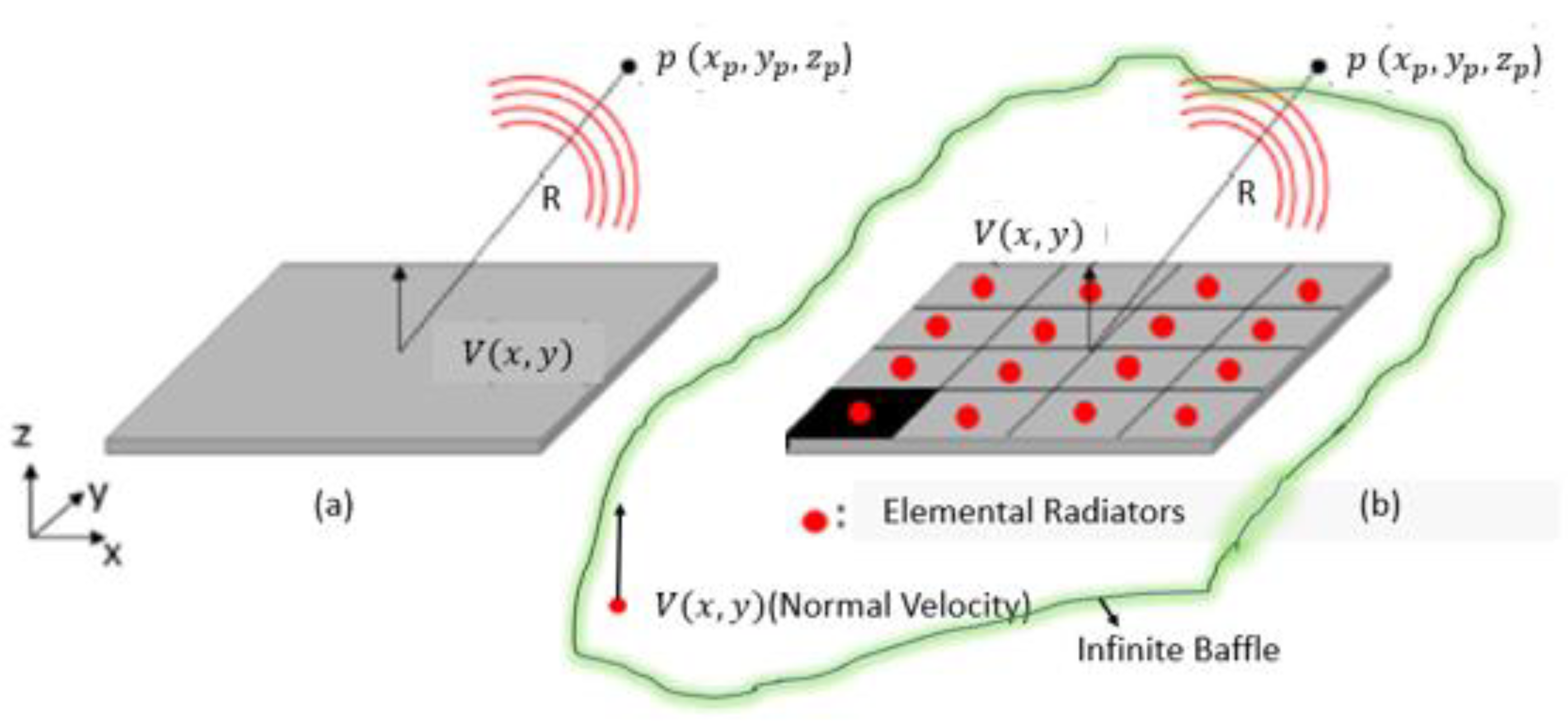
2.4. Surface Velocity Computation in Normal Direction

The out of plane displacement of the P-FGM plate excited by point load in the center is given by [32]
w x , y = 1 I 0 a b i = 1 s s m = 1 M n = 1 N F i     ϕ m n x , y ϕ m n x , y γ ω m n 2 1 + j ψ ω 2
where,   m and n   are   the   modal   indices of the order M and N , respectively. ω is the excitation frequency, F i is 1N point load applied at the center of the P-FGM plate, ψ is the damping loss factor, and γ is given by
γ = 1 S 0 a 0 b ϕ m n 2 x , y d x d y
The normal velocity of plate at any coordinate x , y is [32,54,55,56]
V x , y = j ω w x , y e j ω t

2.5. Computation of Sound Radiation Fields

The Rayleigh Integral gives the acoustic pressure for any point in the half-space x p , y p , z p as shown in Figure 2.
p x p , y p , z p = j ω ρ 0 2 π S V x , y e j κ R R d S
where R = x x s = x p x 2 + y p y 2 + z p 2 is the distance between the source point x s = x , y , 0 on the plate surface to the observation point x = x p , y p , z p with z p 0 The density of the acoustic medium, air is given by ρ 0 , κ is the acoustic wavenumber, c 0 is the speed of sound in acoustic medium air, and S is the plate’s radiating surface. Each element can also be considered a compact acoustic source, resembling a monopole source. S e = d x d y , gives the elemental area, where dx and dy are the element sizes in the x and y directions, respectively.
Every elemental radiator has a constant velocity [32,52] because the characteristics length of each elemental radiator is smaller than acoustic and structural wavelengths.
Thus, Equation (29) can be expressed in discretized form as
p x p , y p , z p = j ω ρ 0 2 π s V M , N e j κ R R d x d y
For a meshed P-FGM plate, Equation (30) can be expressed as an impedance matrix
p Z v V
Writing Equations (30) and (31) in terms of impedance matrix Z v as
Z v i l = j ω ρ 0 S e 2 π e j κ R i l R i l ;       for   i , l = M , N
where S e is the i t h elemental radiator area located at source point x , y , 0 and R i l denotes the distance from i t h to l t h element located at observation point x p , y p , 0 . For Green’s function integrand [10,32], the reciprocity principle holds.
( e j κ R i l R i l )   i . e .   G x s | x = G ( x | x s )
The radiation resistance matrix R m a t   is defined per relation R m a t = S e 2 R e Z v as given by [35], which converts to
R m a t = ω m n 2 ρ 0 S e 2 4 π c 1 s i n   κ R 12 k R 12 s i n   κ R 1 N k R 1 N s i n   κ R 21 k R 21 1 s i n   κ R N 1 k R N 1 1  
Because of reciprocity, R m a t is symmetric, real, and positive definite. Equation (33)’s matrix elements are determined by the acoustic medium’s properties, the natural frequencies and geometry of the P-FGM plate. As a result, sound power from each of the elemental radiators W e ¯ is given as
W e ¯ = S e 2 R e { ( V } Z v V ) = V R m a t V
where V is the normal surface velocity vectors of each elemental radiator and * denotes the complex conjugate. Considering all the elemental radiators, the total approximate sound power can be rewritten as
W = W e ¯    
The SPL in (dB) is computed by
W dB = 10 l o g 10 W / W r e f ; with   W r e f = 10 12 W
The radiation efficiency can be calculated by
σ = W 1 2 ρ 0 c S < v 2 >  
for < v 2 > is the mean square average normal velocity of the plate and is given by
< v 2 > = 1 2 S S V x , y V x , y d S M N 2 a b 2 V V
The V r m s is given by
V r m s = V V 2

3. Results and Discussion

The sound radiation fields are computed by solving Rayleigh Integral in MATLAB using the present approach mentioned in the aforementioned topic. This section discusses the validation studies and parametric effects of various parameters on the sound radiation fields.

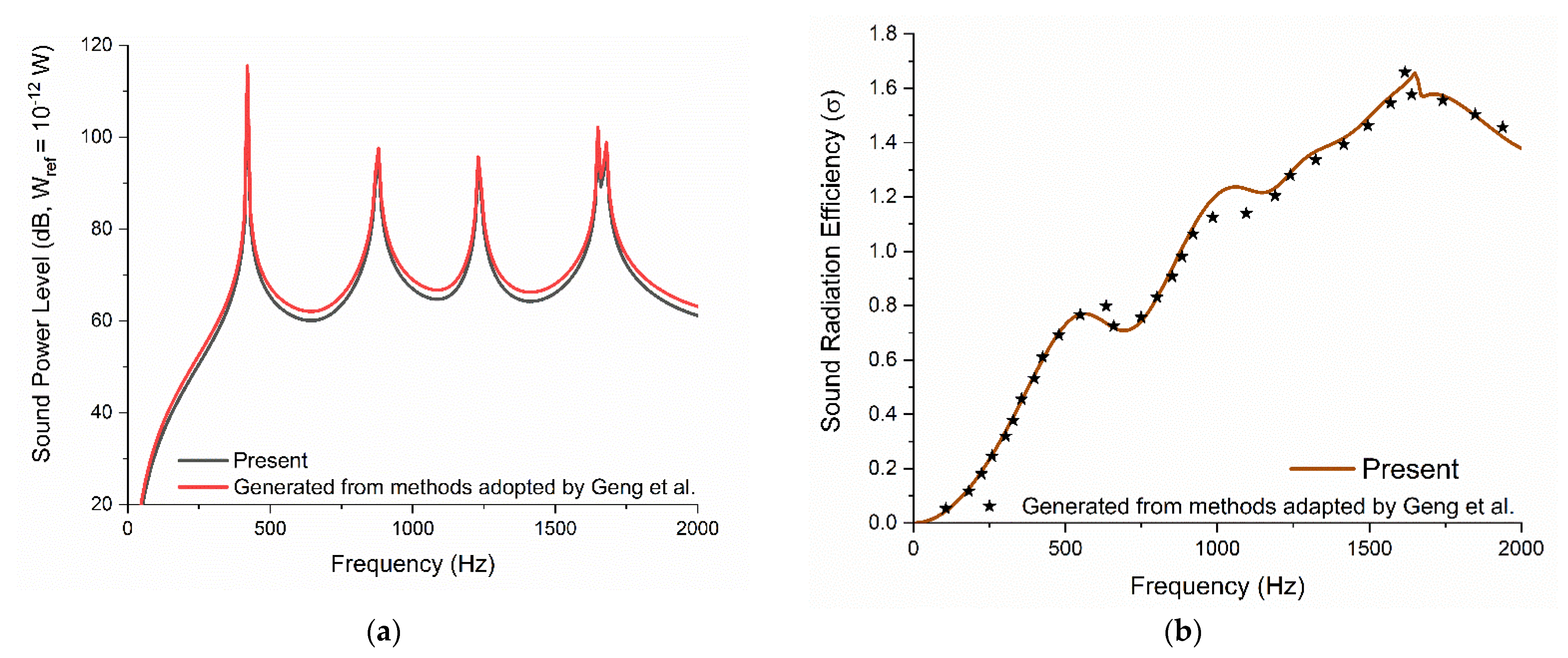
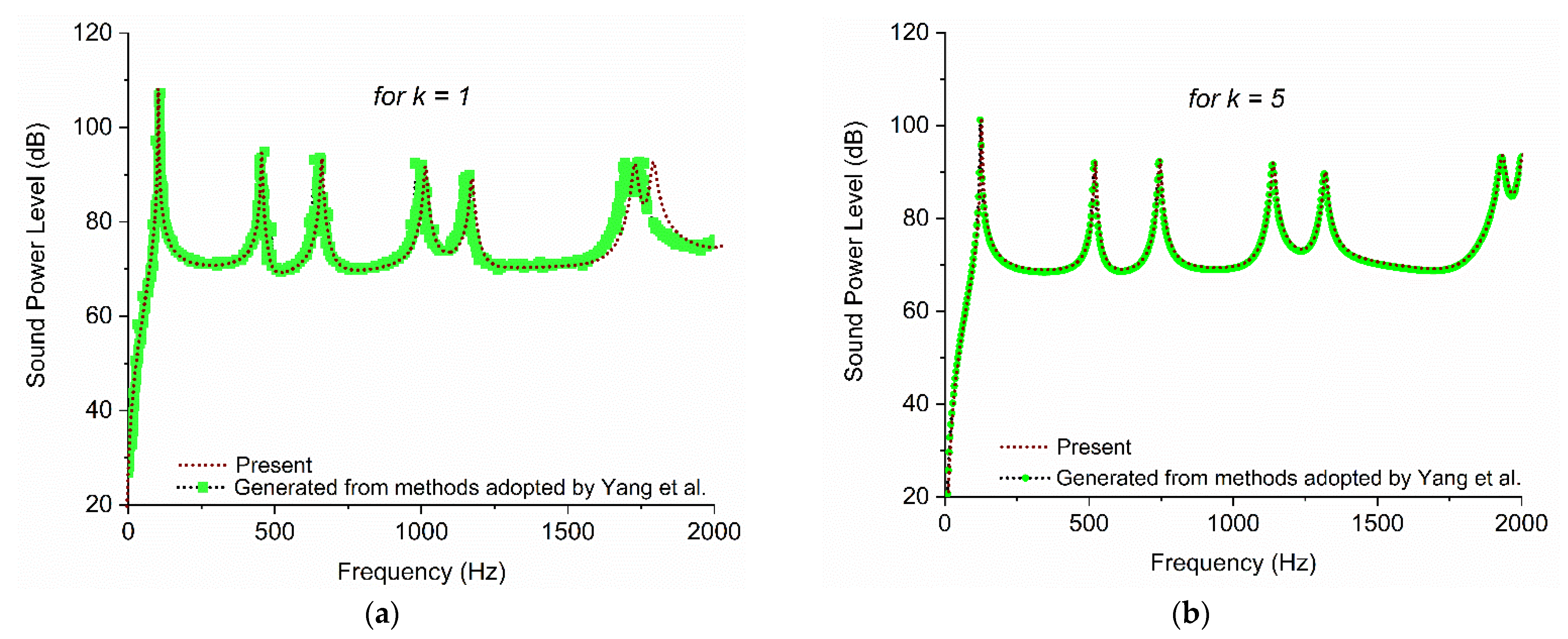
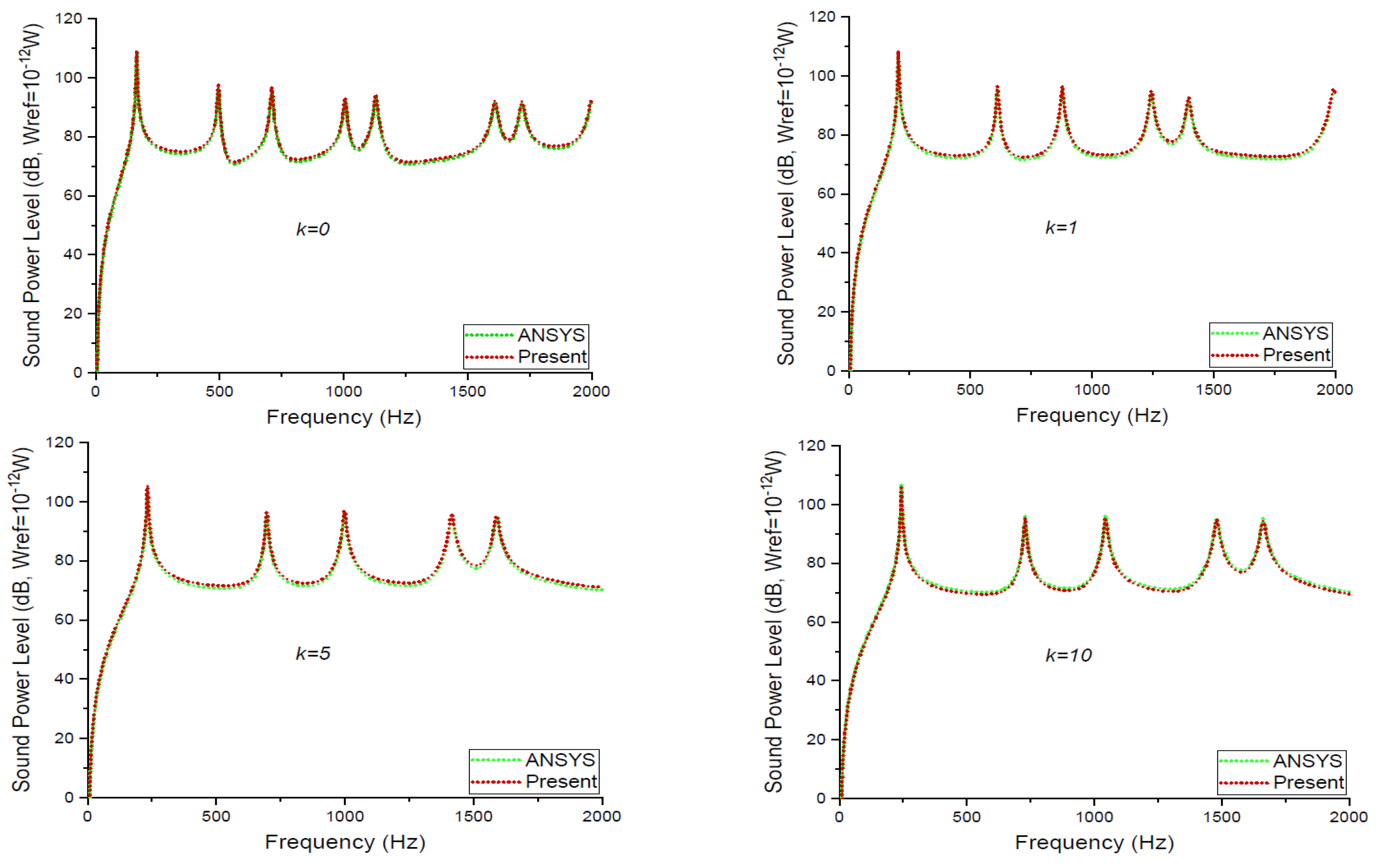
3.1. Comparative Study with the Available Published Results

The P-FGM is reduced to a homogeneous isotropic plate when k = 0. As a result, in Figure 3, the sound radiation fields computed by the aforementioned present approach are compared to those calculated by the method used by Geng et al. [7]. The assumption used in this study is that the size of the element is smaller than half of the structural and acoustic wavelength, leading to constant normal velocity over each elemental radiator. The constant velocity eases solving the Rayleigh integral by elemental radiator approach with radiation resistance matrix. Geng et al. [7] used the direct integration approach with the assumption that the plate is significantly thin (a/h = 40). An excellent agreement is observed in Figure 3.
For two values of the power-law index, k = 1 and 5, the sound power level is computed using the present approach and cross-compared against results in Yang et al. [28] and illustrated in Figure 4. In addition to above assumption mentioned in Section 3.1, the thermal effects are ignored. Furthermore, the plate is assumed to be placed in an infinite rigid baffle. In general, a good agreement is obtained in Figure 4. A small discrepancy is found at higher frequencies for k = 1 because Yang et al. [28] used first-order shear deformation theory with subspace method, while in the present paper, classical plate theory with elemental radiator approach is used. Yang et al. [28] used a frequency resolution of 1 Hz for a frequency range of 0 to 2000 Hz, while in the current paper, the frequency resolution is 3 Hz.
Figure 5 compares the sound power level radiated from the vibrating P-FGM plate computed using the present approach and finite element package, Ansys. Al\/Al_2 0_3 P-FGM is the material composition used for the clamped FGM plate. In Ansys, SOLID185 and Contact174 elements are used for structural modeling, while FLUID221 elements are used for acoustic medium modeling. The results show a high level of agreement.

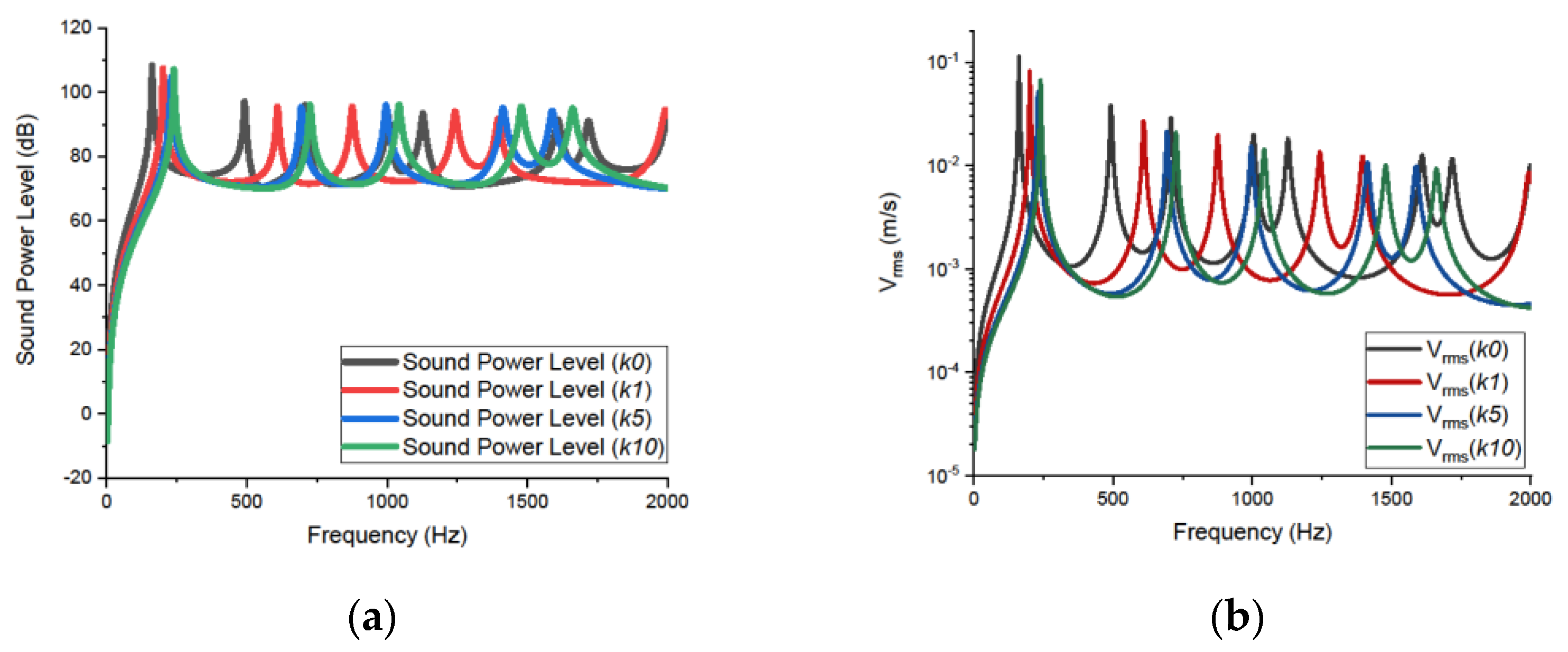
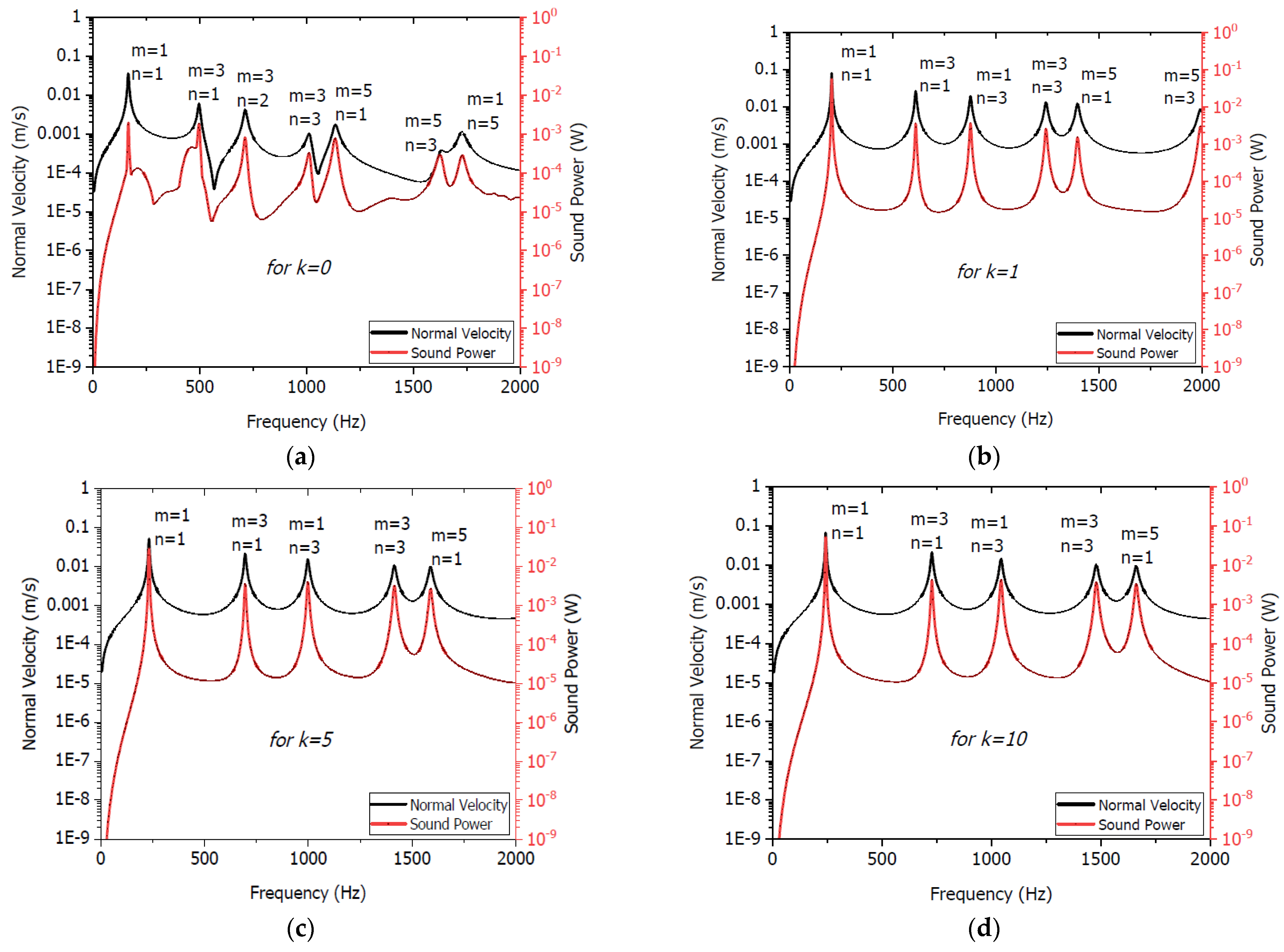
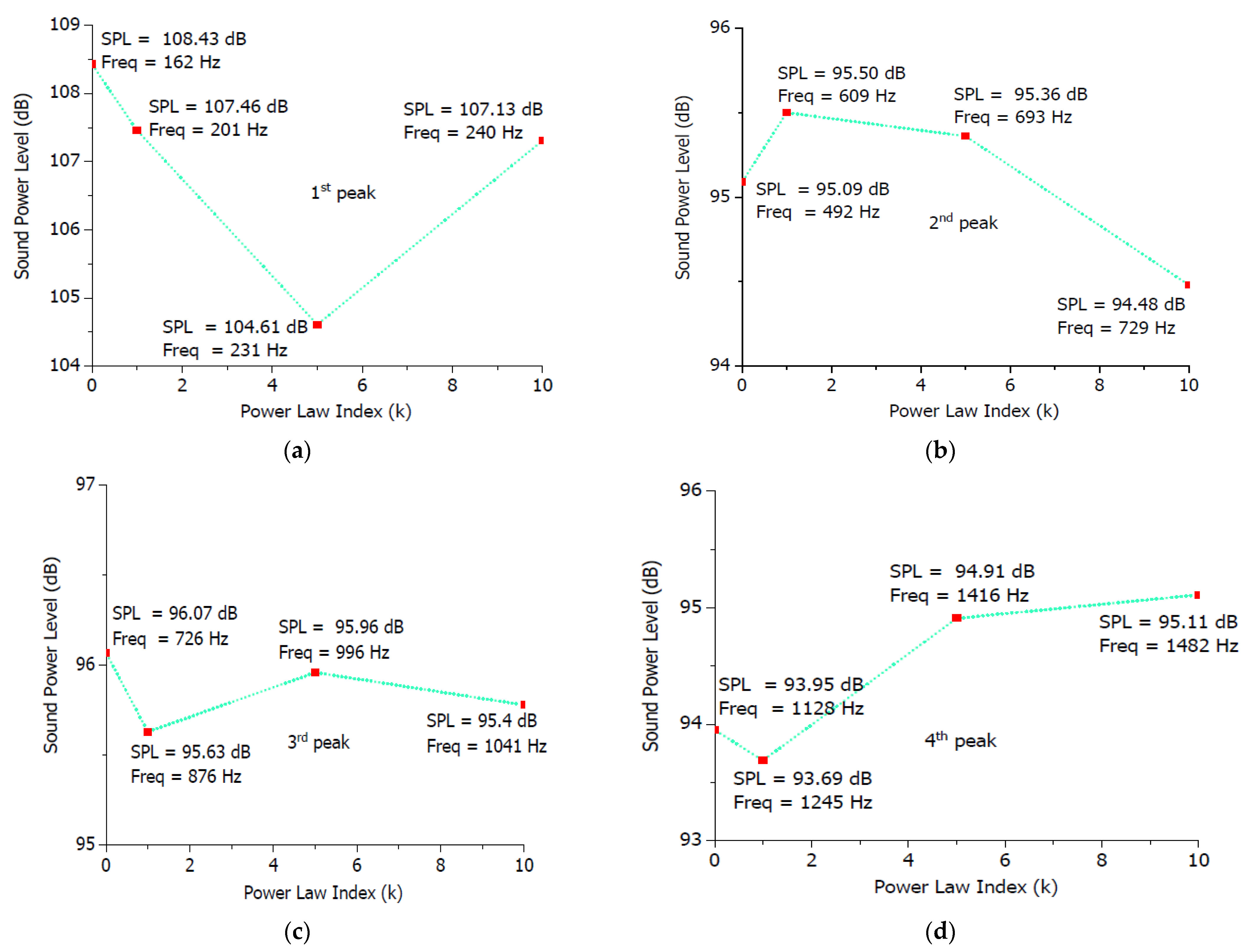
3.2. Effects of the Power-Law Index on the Sound Radiation Fields of P-FGM Plate

Figure 6 depicts the effect of the power-law index, k, on the sound power level and rms velocity of the FGM plate. For different values of the power-law index, the pattern variation in sound power level with frequency is similar. Furthermore, the peaks of the sound power level shift to higher frequencies.
The influence on the SPL peaks is further investigated for the plate’s normal V_rms peaks, different power-law indexes, k, and plate modal indices (m, n), as shown in Figure 7 and Figure 8. It was discovered that sound power level peaks at the same frequencies correlate well with normal velocity peaks. The velocity profiles, also known as mobility response curves, depict the relationship between how sound is emitted at the FGM plate’s surface. In Figure 7, the velocity profile peaks contribute significantly to the sound power level peaks. Furthermore, as illustrated in Figure 8, axisymmetric modes for various power-law indexes significantly contribute to sound power level. The modes shapes are only shown for k = 1 for brevity. As illustrated in Figure 7a, the modal density contribution to plate velocity is greatest for the investigated frequency range up to 2000 Hz for the power-law index k = 0. As the power-law index, k, increases, the modal density’s contribution to plate velocity decreases, as shown in Figure 7b,c.
Figure 9 illustrates sound power peaks variation with ‘k’ and rms velocity. It illustrates that peak sound power level does not monotonically increase with the increase in power-law indexes. As per Figure 9, a critical value of the power-law index exists, for which the corresponding sound power level peak is minimum [29]. Because each of these peaks corresponds to a different frequency, a proper combination of the power-law index, k, and frequency range will aid in proper material tailoring for the P-FGM plate’s sound radiation behavior. In the low-frequency band around 231 Hz, for example, a power-law index of around five will help lower the first sound power level peak, as shown in Figure 9a. This type of information is especially important for designing for sound radiation from the P-FGM plate. It is noteworthy that as the power-law index changes, the modal frequency changes that leads to change in the contributing modes. These contributing modes have significant effects on the sound radiation fields radiated by the P-FGM plates. Due to continuous variation in contributing modes, with the change in power-law indexes, the sound power level does not always increase with increase in power-law index.

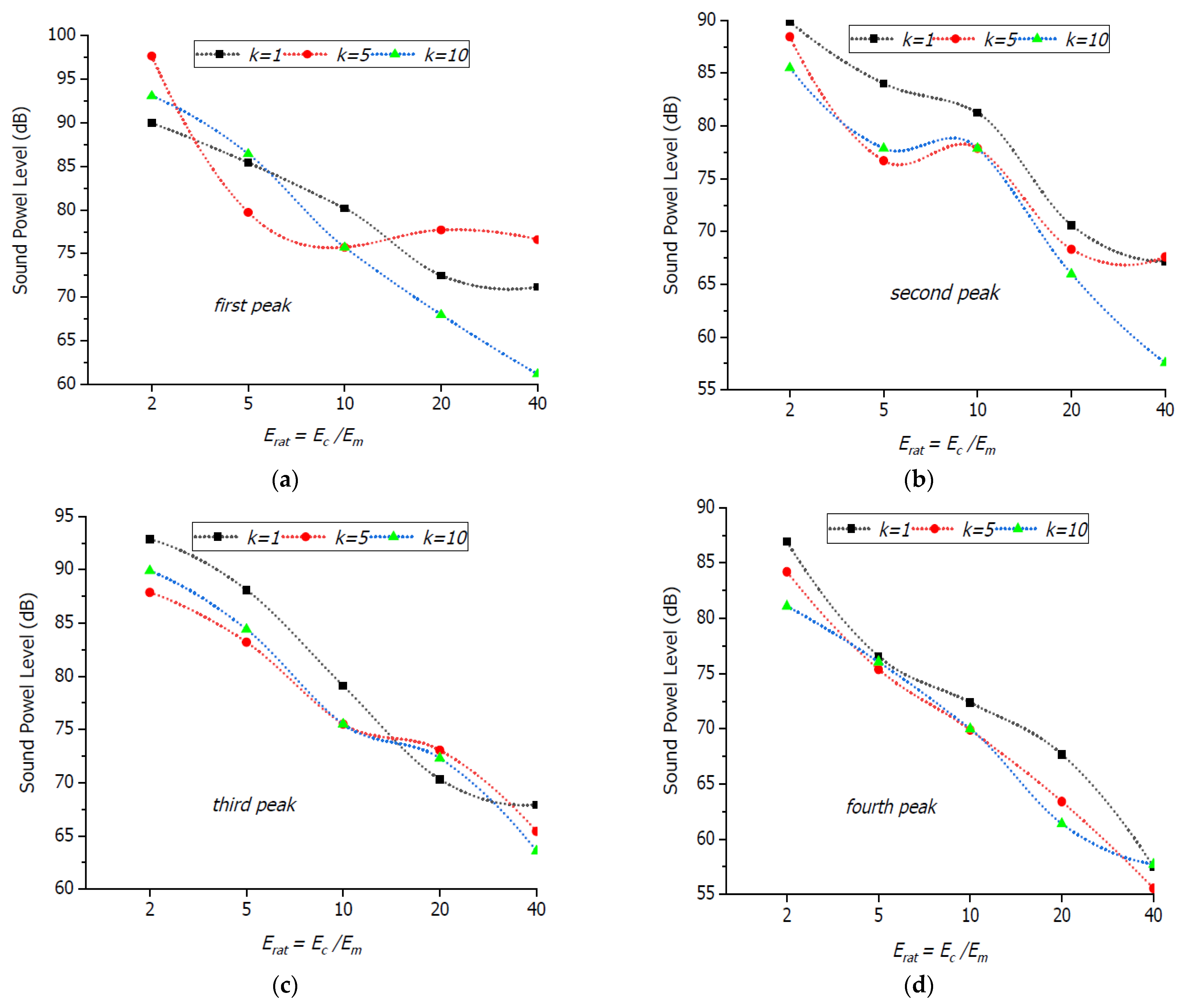
3.3. Influence of Erat = Ec/Em Ratio on Sound Radiation Fields

Figure 10 illustrates the influence of the parameter Erat on sound power level for power-law indexes, k = 1, 5, and 10 similar to as reported by researchers [57]. The effects of modulus ratios on sound power level are documented in this research. A frequency shift is observed in the stiffness control region (first mode—the region of interest) with an increase in modulus ratios.
As E r a t increases, a decrease in sound power level peaks is observed. E r a t denotes the elasticity ratio of ceramic and metal constituents. To better understand the effect of E r a t = E c / E m on the peaks of sound power level, Figure 11 is presented. Obviously, the sound power level decreases with an increase in modulus ratios, and SPL peaks shift towards the right. When the power-law index, k increases, and the SPL radiated by the P-FGM plate increases. The findings suggest that the parameter E r a t and the power-law index, k, could be used as design variables to reduce the sound radiation.

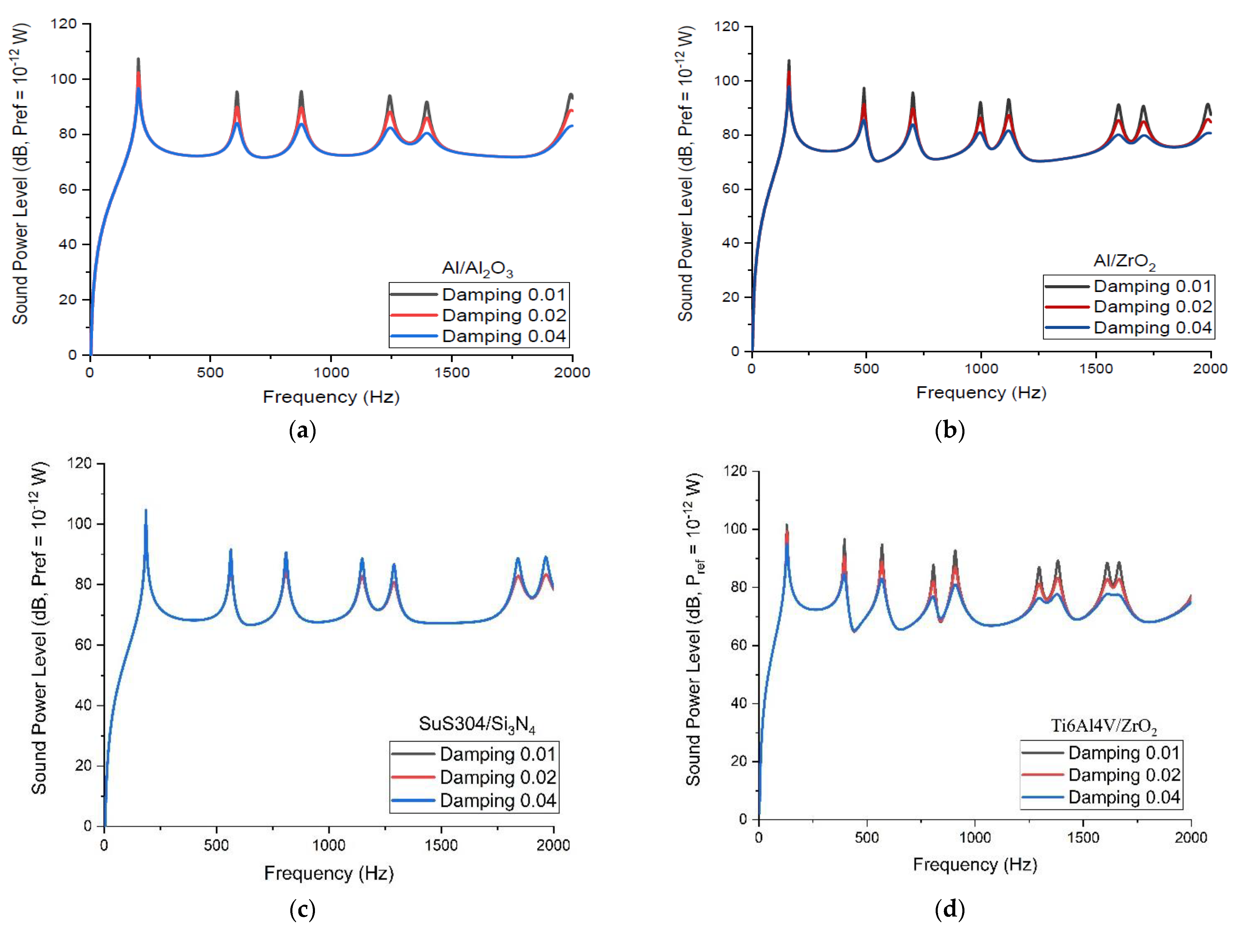
3.4. Influence of Damping Loss Factor on the Sound Power Level of the P-FGM Constituents

Figure 12 illustrates the SPL levels radiated by four distinct P-FGM plate constituents with varying damping loss factors for k = 1. It is found that with the P-FGM material Ti6Al4V/ZrO2, the decrease in sound power peak is more pronounced. The material Ti6Al4V/ZrO2 is less rigid than Al/Al2O3 SuS304/Si3N4, and Al/ZrO2, which reduces sound power level. The sound power level peaks are also lowered when the damping loss factor increases. The variation is shown only for the power-law index, k = 1, for the sake of brevity.

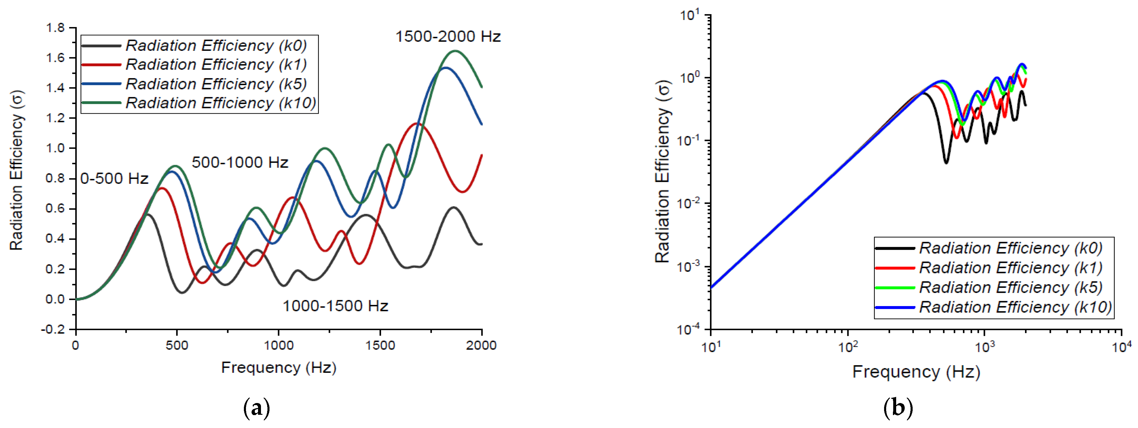
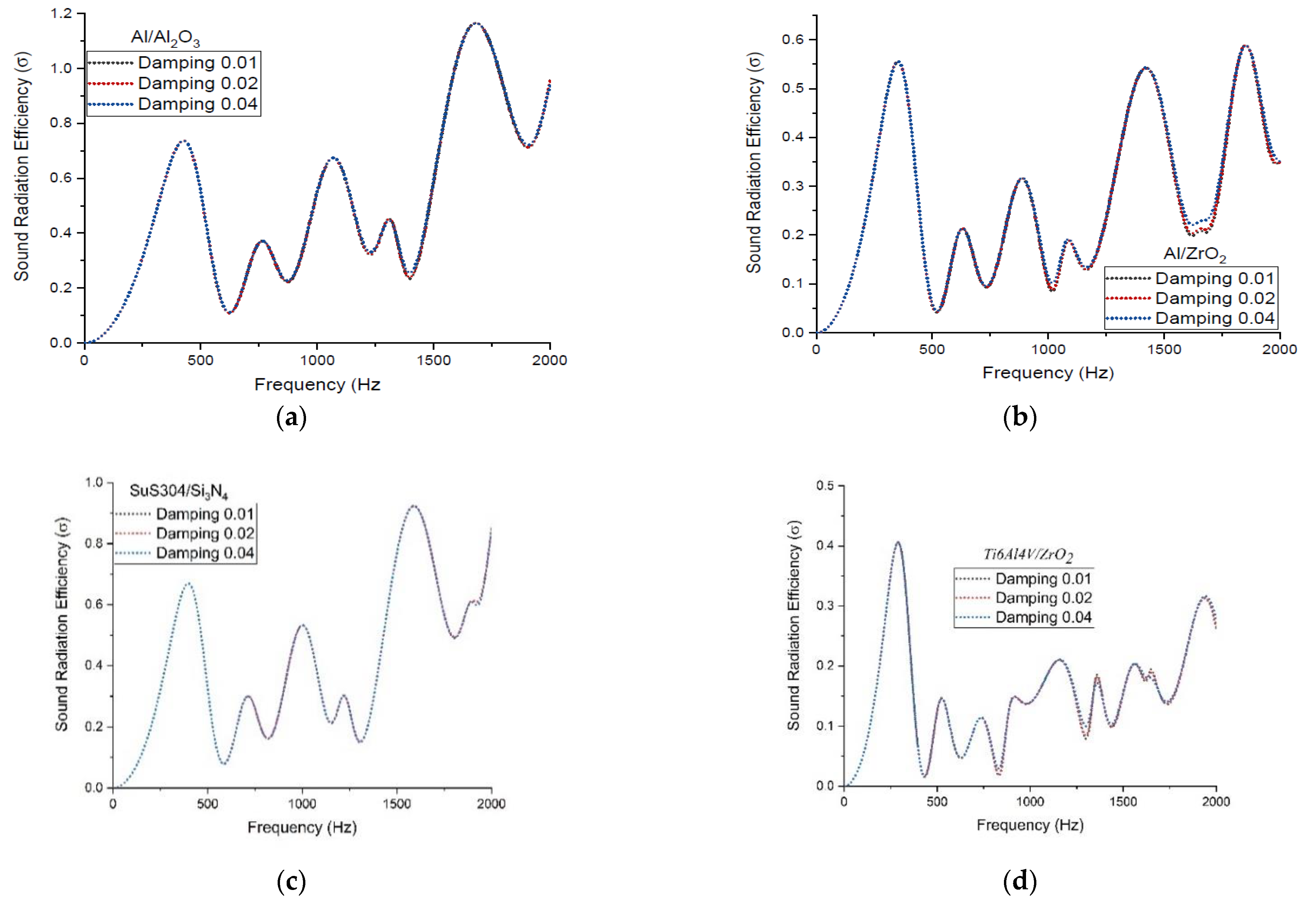
3.5. Radiation Efficiencies Variation with Power-Law Indexes, Varied P-FGM Constituents, and Effects of Damping Loss Factor

The radiation efficiency is a metric that measures how well a structure radiates sound in an acoustic medium. Figure 13 shows how the variable, k, affects the radiation efficiency of a P-FGM plate. With an increase in the power-law index, the first radiation efficiency peak rises. It is also worth noting that the radiation efficiency for a wide range of forcing frequencies (say, 500–1500 Hz) is lower for the power-law index, k = 1. This decrease in radiation efficiency suggests that choosing the right variable ‘k’ and the frequency range of excitation can be well utilized as a design variable to control the sound radiation of vibrating P-FGM plates. In this case, the radiation efficiency peak is highest for the power-law index, k = 10, near 1900–2000 Hz.
Figure 14 compares the radiation efficiencies of four P-FGM plates on a normal scale with different damping loss factors. It is clear that different damping loss factors have minute effects on the radiation efficiency, while P-FGM constituents affect radiation efficiency. It is also found that sound radiation efficiency increases with an increase in frequency until it approaches its maximum amplitude and then tries to approach towards unity. The lowest radiation efficiency is possessed by the Ti 6 Al 4 V / ZrO 2 FGM plate signifying it to be a better sound radiator as it has lower stiffness than other FGM plates for k = 1. Thus, the order of sound radiation efficiency by P-FGM plates is Ti 6 Al 4 V / ZrO 2 < Al / ZrO 2 < SuS 304 / Si 3 N 4 < Al / Al 2 O 3 .

4. Conclusions

In this paper, the analytical solution to the vibro-acoustic response of a vibrating clamped P-FGM plate is analyzed. Several validation studies and parametric effects are presented. Listed below are the conclusions of the present research:
(a)
The sound radiation fields validated with ANSYS and literature are in good agreement.
(b)
The sound power level monotonically increases with an increase in the power-law index because of a reduction in the stiffness of the FGM plate.
(c)
However, contrary to what other authors [29] have claimed, the acoustic response of P-FGM plates does not appear to always increase with an increase in the power-law index in the current study.
(d)
The current findings lead to conclude that there exists a key value of the power-law index for which the sound power level is at minimum in a specific frequency range.
(e)
Sound power level peak decreases and level shifts to higher frequencies with an increase in E r a t = E c / E m = 2, 5, 10, 20, and 40.
(f)
It can also be said that the P-FGM plates’ material distribution (due to variation in power-law index ‘k’) plays the major role in the computation of the sound radiation of the FGM plate because it characterizes the stiffness variation of the structure.
Hence, it is found that the power-law index does not appear to have a significant impact on radiation efficiency at low frequencies of less than 250 Hz. Overall, the mono-ceramic P-FGM plate can be considered as a better sound radiator because of higher stiffness.

Author Contributions

Conceptualization, V.R.; Formal analysis, B.N.S.; Investigation, B.N.S.; Methodology, V.R.; Software, S.D.; Supervision, V.R. and R.N.H.; Writing—original draft, B.N.S.; Writing—review & editing, R.J. and K.Ř. All authors have read and agreed to the published version of the manuscript.

Funding

This research received no external funding.

Conflicts of Interest

The authors declare no conflict of interest.

References

  1. Kumar, S.; Ranjan, V.; Jana, P. Free vibration analysis of thin functionally graded rectangular plates using the dynamic stiffness method. Compos. Struct. 2018, 197, 39–53. [Google Scholar] [CrossRef]
  2. Chi, S.-H.; Chung, Y.-L. Mechanical behavior of functionally graded material plates under transverse load—Part I: Analysis. Int. J. Solids Struct. 2006, 43, 3657–3674. [Google Scholar] [CrossRef] [Green Version]
  3. Chi, S.-H.; Chung, Y.-L. Mechanical behavior of functionally graded material plates under transverse load—Part II: Numerical results. Int. J. Solids Struct. 2006, 43, 3675–3691. [Google Scholar] [CrossRef] [Green Version]
  4. Wallace, C.E. Radiation Resistance of a Rectangular Panel. J. Acoust. Soc. Am. 1972, 51, 946–952. [Google Scholar] [CrossRef]
  5. Putra, A.; Thompson, D. Sound radiation from rectangular baffled and unbaffled plates. Appl. Acoust. 2010, 71, 1113–1125. [Google Scholar] [CrossRef]
  6. Putra, A.; Shyafina, N.; Thompson, D.; Muhammad, N.; Jailani, M.; Nor, M.; Nuawi, Z. Modelling Sound Radiation from a Baffled Vibrating Plate for different Boundary Conditions Using an Elementary Source Technique. InterNoise 2014, 249, 5812–5819. [Google Scholar]
  7. Geng, Q.; Li, H.; Li, Y. Dynamic and acoustic response of a clamped rectangular plate in thermal environments: Experiment and numerical simulation. J. Acoust. Soc. Am. 2014, 135, 2674–2682. [Google Scholar] [CrossRef] [Green Version]
  8. Geng, Q.; Li, Y. Solutions of dynamic and acoustic responses of a clamped rectangular plate in thermal environments. J. Vib. Control 2016, 22, 1593–1603. [Google Scholar] [CrossRef]
  9. Tao, J.; Ge, H.; Qiu, X. A new rule of vibration sampling for predicting acoustical radiation from rectangular plates. Appl. Acoust. 2006, 67, 756–770. [Google Scholar] [CrossRef]
  10. Kirkup, S. Computational solution of the acoustic field surrounding a baffled panel by the Rayleigh integral method. Appl. Math. Model. 1994, 18, 403–407. [Google Scholar] [CrossRef]
  11. Åbom, M.; Bodén, H. A method for estimating the sound power radiated from plates with prescribed excitation in the multi-mode region. Appl. Acoust. 1987, 22, 203–212. [Google Scholar] [CrossRef]
  12. Feit, D. Sound Radiation from Orthotropic Plates. J. Acoust. Soc. Am. 1970, 47, 388–389. [Google Scholar] [CrossRef]
  13. Reynders, E.; Van Hoorickx, C.; Dijckmans, A. Sound transmission through finite rib-stiffened and orthotropic plates. Acta Acust. United Acust. 2016, 102, 999–1010. [Google Scholar] [CrossRef]
  14. Zhou, K.; Su, J.; Hua, H. Closed Form Solutions for Vibration and Sound Radiation of Orthotropic Plates under Thermal Environment. Int. J. Struct. Stab. Dyn. 2018, 18, 1850098. [Google Scholar] [CrossRef]
  15. Kam, T.Y.; Lee, B.Y. Sound radiation of elastically restrained stiffened orthotropic plates. J. Acoust. Soc. Am. 2012, 131, 3232. [Google Scholar] [CrossRef]
  16. Cao, X.; Hua, H.; Zhang, Z. Sound radiation from shear deformable stiffened laminated plates. J. Sound Vib. 2011, 330, 4047–4063. [Google Scholar] [CrossRef]
  17. Cao, X.; Hua, H. Sound Radiation from Shear Deformable Stiffened Laminated Plates with Multiple Compliant Layers. ASME J. Vib. Acoust. 2012, 134, 51001. [Google Scholar] [CrossRef]
  18. Hao, W.F.; Wang, S.; Kam, T.Y. Sound Radiation of Laminated Composite Plates Partially Supported by Elastic Restraints. In Proceedings of the 13th AIAA/CEAS Aeroacoustics Conference (28th AIAA Aeroacoustics Conference), Rome, Italy, 21–23 May 2007; Volume 28, p. 3571. [Google Scholar]
  19. Li, X.; Yu, K.; Zhao, R. Vibro-acoustic response of a clamped rectangular sandwich panel in thermal environment. Appl. Acoust. 2018, 132, 82–96. [Google Scholar] [CrossRef]
  20. Arunkumar, M.P.; Jagadeesh, M.; Pitchaimani, J.; Gangadharan, K.V.; Babu, M.L. Sound radiation and transmission loss characteristics of a honeycomb sandwich panel with composite facings: Effect of inherent material damping. J. Sound Vib. 2018, 383, 221–232. [Google Scholar] [CrossRef]
  21. Sorrenti, M.; Di Sciuva, M.; Tessler, A. A robust four-node quadrilateral element for laminated composite and sandwich plates based on Refined Zigzag Theory. Comput. Struct. 2020, 242, 106369. [Google Scholar] [CrossRef]
  22. Chandra, N.; Gopal, K.V.N.; Raja, S. Vibro-acoustic response of sandwich plates with functionally graded core. Acta Mech. 2015, 228, 2775–2789. [Google Scholar] [CrossRef]
  23. Chandra, N.; Raja, S.; Gopal, K.V.N. A Comprehensive Analysis on the Structural–Acoustic Aspects of Various Functionally Graded Plates. Int. J. Appl. Mech. 2015, 7, 1550072. [Google Scholar] [CrossRef]
  24. Yang, T.; Huang, Q.; Li, S. Three-Dimensional Elasticity Solutions for Sound Radiation of Functionally Graded Materials Plates considering State Space Method. Shock Vib. 2016, 2016, 1403856. [Google Scholar] [CrossRef] [Green Version]
  25. Hasheminejad, S.M.; Shabanimotlagh, M. Sound Insulation Characteristics of Functionally Graded Panels. Acta Acust. United Acust. 2008, 94, 290–300. [Google Scholar] [CrossRef]
  26. Huang, C.; Nutt, S. An analytical study of sound transmission through unbounded panels of functionally gradedmaterials. J. Sound Vib. 2011, 330, 1153–1165. [Google Scholar] [CrossRef]
  27. Zhou, K.; Lin, Z.; Huang, X.; Hua, H. Vibration and sound radiation analysis of temperature-dependent porous functionally graded material plates with general boundary conditions. Appl. Acoust. 2019, 154, 236–250. [Google Scholar] [CrossRef]
  28. Yang, T.; Zheng, W.; Huang, Q.; Li, S. Sound radiation of functionally graded materials plates in thermal environment. Compos. Struct. 2016, 144, 165–176. [Google Scholar] [CrossRef]
  29. Chandra, N.; Raja, S.; Gopal, K.N. Vibro-acoustic response and sound transmission loss analysis of functionally graded plates. J. Sound Vib. 2014, 333, 5786–5802. [Google Scholar] [CrossRef]
  30. Belegundu, A.D.; Salagame, R.R.; Koopmann, G.H. A General Optimization Approach for Minimizing Acoustic Power Using Finite Elements; SAE Technical Paper 930198. In Proceedings of the International Congress & Exposition, Dearborn, MI, USA, 1 March 1993. [Google Scholar] [CrossRef]
  31. Chen, K.; Koopmann, G.H. Active Control of Low-Frequency Sound Radiation from Vibrating Panel Using Planar Sound Sources. ASME J. Vib. Acoust. 2002, 124, 2–9. [Google Scholar] [CrossRef]
  32. Arenas, J.; Crocker, M. Sound Radiation Efficiency of a Baffled Rectangular Plate Excited by Harmonic Point Forces Using its Surface Resistance Matrix. Int. J. Acoust. Vib. 2002, 7, 217–229. [Google Scholar] [CrossRef]
  33. Arenas, J.P. Numerical computation of the sound radiation from a planar baffled vibrating surface. J. Comput. Acoust. 2008, 16, 321–341. [Google Scholar] [CrossRef]
  34. Arenas, J.P. Matrix Method for Estimating the Sound Power Radiated from a Vibrating Plate for Noise Control Engineering Applications. Lat. Am. Appl. Res. 2009, 39, 345–352. [Google Scholar]
  35. Mao, Q.; Pietrzko, S. Control of Noise and Structural Vibration: A MATLAB®-Based Approach; Springer: London, UK, 2013; 377p. [Google Scholar]
  36. Nichols, R.H.; Lee, C.P.; Wang, T.G. Sound acoustics radiation from the vibration of functionally graded plates. J. Acoust. Soc. Am. 1988, 83, 62459–62461. [Google Scholar]
  37. Naghshineh, K.; Koopmann, G.H.; Belegundu, A.D. Material tailoring of structures to achieve a minimum radiation condition. J. Acoust. Soc. Am. 1992, 92, 841–855. [Google Scholar] [CrossRef]
  38. Putra, A.; Thompson, D. Sound radiation from perforated plates. J. Sound Vib. 2007, 329, 4227–4250. [Google Scholar] [CrossRef] [Green Version]
  39. Reddy, J.N.; Chin, C.D. Thermomechanical analysis of functionally graded cylinders and plates. J. Therm. Stress. 1998, 21, 593–626. [Google Scholar] [CrossRef]
  40. Reddy, J.N. Analysis of functionally graded plates. Int. J. Numer. Methods Eng. 2000, 684, 663–684. [Google Scholar] [CrossRef]
  41. Zhang, D.-G.; Zhou, Y.-H. A theoretical analysis of FGM thin plates based on physical neutral surface. Comput. Mater. Sci. 2008, 44, 716–720. [Google Scholar] [CrossRef]
  42. Yin, S.; Yu, T.; Liu, P. Free Vibration Analyses of FGM Thin Plates by Isogeometric Analysis Based on Classical Plate Theory and Physical Neutral Surface. Adv. Mech. Eng. 2013, 5, 634584. [Google Scholar] [CrossRef]
  43. Abrate, S. Functionally graded plates behave like homogeneous plates. Compos. Part B Eng. 2008, 39, 151–158. [Google Scholar] [CrossRef]
  44. Thai, C.H.; Kulasegaram, S.; Tran, L.V.; Nguyen-Xuan, H. Generalized shear deformation theory for functionally graded isotropic and sandwich plates based on isogeometric approach. Comput. Struct. 2014, 141, 94–112. [Google Scholar] [CrossRef]
  45. Mori, T.; Tanaka, K. Average stress in matrix and average elastic energy of materials with misfitting inclusions. Acta Met. 1973, 21, 571–574. [Google Scholar] [CrossRef]
  46. Jha, D.K.; Kant, T.; Singh, R.K. A critical review of recent research on functionally graded plates. Compos. Struct. 2013, 96, 833–849. [Google Scholar] [CrossRef]
  47. Abrate, S. Free vibration, buckling, and static deflections of functionally graded plates. Compos. Sci. Technol. 2006, 66, 2383–2394. [Google Scholar] [CrossRef]
  48. Cinefra, M.; Soave, M. Accurate vibration analysis of multi-layered plates made of functionally graded materials. Mech. Adv. Mater. Struct. 2011, 18, 3–13. [Google Scholar] [CrossRef]
  49. Thai, H.-T.; Vo, T.P. A new sinusoidal shear deformation theory for bending, buckling, and vibration of functionally graded plates. Appl. Math. Model. 2013, 37, 3269–3281. [Google Scholar] [CrossRef]
  50. Zhang, Y.B.; Bi, C.X.; Chen, X.Z.; Chen, J. Computation of acoustic radiation from vibrating structures in motion. Appl. Acoust. 2008, 69, 1154–1160. [Google Scholar] [CrossRef]
  51. Li, W.; Geng, Q.; Li, Y.M. Theoretical Analyses of Vibration and Sound Radiation Responses of Heated Symmetric Laminated Plates in Pre- and Post-Buckling Ranges. Appl. Mech. Mater. 2015, 775, 23–27. [Google Scholar] [CrossRef]
  52. Morimoto, T.; Tanigawa, Y.; Kawamura, R. Thermal buckling of functionally graded rectangular plates subjected to partial heating. Int. J. Mech. Sci. 2006, 48, 926–937. [Google Scholar] [CrossRef]
  53. Ruan, M.; Wang, Z.-M. Transverse vibrations of moving skew plates made of functionally graded material. J. Vib. Control 2016, 22, 3504–3517. [Google Scholar] [CrossRef]
  54. Singh, B.N.; Ranjan, V.; Hota, R.N. Vibroacoustic response from thin exponential functionally graded plates. Ing. Arch. 2022, 92, 2095–2118. [Google Scholar] [CrossRef]
  55. Singh, B.N.; Hota, R.N.; Dwivedi, S.; Jha, R.; Ranjan, V. Acoustic Response of Sigmoid Functionally Graded Thin Plates: A Parametric Investigation. J. Vib. Eng. Technol. 2022, 1–21. [Google Scholar] [CrossRef]
  56. Singh, B.N.; Ranjan, V.; Hota, R. Vibroacoustic response of mode localized thin functionally graded plates using physical neutral surface. Compos. Struct. 2022, 287, 115301. [Google Scholar] [CrossRef]
  57. Ali, M.I.; Azam, M.S.; Ranjan, V.; Bannerjee, J.R. Free vibration of sigmoid functionally graded plate using Dynamic Stiffness Method and Wittrick-Williams Algorithm. J. Comput. Struct. 2021, 244, 106424. [Google Scholar] [CrossRef]
Figure 1. P-FGM plate with physical neutral surface.
Applsci 12 07707 g001
Figure 2. Schematic diagram of elemental radiators.
Applsci 12 07707 g002
Figure 3. (a) Sound power level (SPL) and (b) radiation efficiency for k = 0 comparison with Geng et al. [7].
Applsci 12 07707 g003
Figure 4. P-FGM plate’s SPL for k = (a) 1 and (b) 5, in comparison with Yang et al. [28].
Applsci 12 07707 g004
Figure 5. Sound power level with present approach and ANSYS for k = 0, 1, 5, and 10.
Applsci 12 07707 g005
Figure 6. (a) SPL and (b) V_rms of clamped P-FGM plates for different k’s.
Applsci 12 07707 g006
Figure 7. Illustration of SPL and V_rms of P-FGM plates on a single plot for power-law indexes k = (a) 0, (b) 1, (c) 5, and (d) 10.
Applsci 12 07707 g007
Figure 8. P-FGM plates contributing modes for k = 0. (a) Mode [1,1] 256.6 Hz; (b) Mode [1,3] 768.74 Hz; (c) Mode [3,1] 1102.2 Hz; (d) Mode [3,2] 1069.5 Hz; (e) Mode [3,3] 1561.9 Hz. (f) Mode [5,1] 1754.5 Hz; (g) Mode [1,5] 1832.2 Hz.
Applsci 12 07707 g008aApplsci 12 07707 g008b
Figure 9. Behavior of variation in k with SPL peaks (a) first peak, (b) second peak, (c) third peak, and (d) fourth peak.
Applsci 12 07707 g009
Figure 10. SPL’s peak shift with E r a t for power-law index, k = 1 and 10.
Applsci 12 07707 g010
Figure 11. Influence on the sound power level peaks for different power-law indexes, k, and modulus ratio Erat (a) first peak, (b) second peak, (c) third peak, and (d) fourth peak.
Applsci 12 07707 g011
Figure 12. Sound power level for (a) Al / Al 2 O 3 , (b) Al / ZrO 2 , (c) SuS 304 / Si 3 N 4 , and (d) Ti 6 Al 4 V / ZrO 2 FGM plates under damping loss factor of 0.01, 0.02, and 0.04.
Applsci 12 07707 g012
Figure 13. Variation of radiation efficiency with power-law indexes, k: (a) normal and (b) log-log scale.
Applsci 12 07707 g013
Figure 14. Radiation efficiency of (a)   Al / Al 2 O 3 , (b) Al / ZrO 2 , (c) SuS 304 / Si 3 N 4 , and (d) Ti 6 Al 4 V / ZrO 2 P-FGM plates under different damping loss factors.
Applsci 12 07707 g014
Table 1. Material properties of different FGM plates [28,55].
Sr. No.Materials Young s   Modulus   ( E ,   P a ) Poisson s   Ratio   ( ν ) Density   ( ρ , kg / m 3 )
1Aluminum (Al)70 × 1090.32700
2 Aluminum   Oxide   ( Al 2 O 3 )380 × 1090.33800
3 Zirconia   ( ZrO 2 )151 × 1090.33000
4 Stainless   Steel   ( SUS 304 )208 × 1090.328166
5 Silicon   Nitride   ( Si 3 N 4 ) 322 × 1090.242370
6Ti-6Al-4V106 × 10110.2984429
Publisher’s Note: MDPI stays neutral with regard to jurisdictional claims in published maps and institutional affiliations.

