Article

Manual Wheelchair Equipped with a Planetary Gear-Research Methodology and Preliminary Results

1
Faculty of Mechanical Engineering, Institute of Machine Design, Poznan University of Technology, 60-965 Poznan, Poland
2
Faculty of Mechanical Engineering, Institute of Mechatronic Devices, Poznan University of Technology, 60-965 Poznań, Poland
*
Author to whom correspondence should be addressed.
Appl. Sci. 2022, 12(15), 7737; https://doi.org/10.3390/app12157737
Submission received: 23 June 2022 / Revised: 23 July 2022 / Accepted: 29 July 2022 / Published: 1 August 2022

Abstract

:

Featured Application

A wheelchair with a planetary gear for adjusting the torque demand to needs of the operator. The results of the preliminary tests show that the muscular effort of the person propelling a wheelchair increases as the gear ratio increases. Varying propelling conditions change the muscle load of the operator and this alters the kinematics of the upper limbs’ movement and tilt of the torso as well. Occurring changes affect the position of the center of gravity—which in turn change the conditions of the resistance to motion. The use of such a wheelchair facilitates movement on soft ground or inclined planes and gives the possibility of increasing the range of movement.

Abstract

The purpose of the study was to create a research methodology for testing the newly developed wheelchair drive, which allows the operator to choose the gear ratio and, thus, makes it possible to change the propulsion torque value. The aim was to choose such conditions in the experiment, that would result in great enough changes in the participant’s muscle load and body kinematics for it to be possible to register them with applied measuring methods. Surface electromyography was used to assess the effort that was required for the propulsion of a wheelchair under different conditions. Additionally, upper limb motion capture measurements were also performed. The preliminary results show that the muscular effort of the participant propelling the wheelchair increases with the load—resulting from both the gear ratio and the inclination angle. At the same time, the position of the motion range of upper limb individual segments changes significantly. Simultaneously, the mean value of the shoulder displacement and its angle of rotation decreases.

1. Introduction

The wheelchair’s purpose is to enable the independent existence of people who are affected by mobility disabilities. The experience of wheelchair users shows that these devices are important for their mental health because they promote increased mobility and allow social interaction development [1,2]. One of the important aspects for the users of these devices is increasing their overall movement distance [3]. Another incentive should concern the torque on the drive wheels [4], which is particularly important when navigating difficult road conditions. Factors that impede the movement of vehicles, such as wheelchairs, include a strong wind, unpaved or dirty surfaces [5,6], hills [7], unevenness, thresholds or stairs. All these factors translate into increased resistance when driving a wheelchair [8] and, thus, require an increased effort from users when propelling a wheelchair.
Manual wheelchairs equipped with technical solutions such as suspension systems to overcome obstacles without special architectural modifications are available [9]. Whereas the authors of [10] provide an overview of electric wheelchairs capable of overcoming obstacles that most often can be encountered by people with disabilities in their immediate surroundings such as uneven terrain, curbs or stairs. They indicate that some of the available projects are only aimed at successfully overcoming terrain obstacles, but which at the same time are not efficient enough to move on a horizontal surface and have limited maneuverability [10]. A variety of wheelchair technical solutions, as well as structures supporting the overcoming of terrain obstacles are available, but the current research trend is toward simplifying the design, lowering the costs [11] and reducing the number of people required to assist in overcoming those terrain obstacles [12]. Electric drive systems aim to significantly increase the functional mobility of disabled people, in particular people with very limited mobility [13,14], but despite their advantages, electric-assisted wheelchairs have some disadvantages, such as difficult transport in the vehicle [4,15], having a limited battery life [15] or a limited use at home [4]. In addition, the need to consider the delay occurring in the control system is characterized by an unnatural interaction with the user [4,16]. Particularly noticeable is the reduced precision of control compared to classic wheelchairs [5], which is due to an increased mass, size and control signal delay occurrence [3]. Moreover, there exists a risk that wheelchair users with electrically assisted propulsion systems may lead to a less active lifestyle limiting their physical development, which in turn may predispose them to many long-term health problems [4,17,18]. It is worth noting that in the case of an electric wheelchair, it is the electric propulsion that completely replaces the operator’s muscular system in the process of propulsion. On the one hand, this is beneficial because the range of the wheelchair and its ability to overcome obstacles depends only on its design and the technical solutions used [4,7,16]. On the other hand, it reduces the physical activity of the operator, which is important because it has a positive effect on the maintenance of the proper functioning of the body.
Currently, a large number of designs of these devices can be observed, which are not necessarily based on an electric drive support, for example, wheelchairs for climbing stairs [10], and wheelchairs with a non-classical mechanical propulsion system [19,20,21,22] (other than classic manual handrims). This is due to the specific requirements that they have to meet. The best possible adaptation to meet the needs and abilities of individual users is beneficial, as it has a positive impact on the efficiency and ergonomics of the wheelchair use. The issues related to the ergonomics of driving with a wheelchair are very up-to-date and concern its use in everyday life [1,23], but also in various sports, such as rugby [16], tennis [24] or basketball [25]. It can be observed that over the last ten years there has been a significant increase in wheelchair court sports participation [26,27].
In the case of a manual wheelchair, the human muscles are the main source of propulsion and the use of assistive technology for a long period of time has consequences for the musculoskeletal system. A significant strain on the upper limb, for example, resulting from an uneven physical load and a finite potential for physical activity, leads to injuries as a result of overuse. [28,29]. Moreover, it is the fitness and physical abilities of individuals that influence the length of the distance and the type of terrain and architectural obstacles that can be overcome. In many cases, the operator is not able to use a wheelchair with manual propulsion in a satisfactory manner and this creates a problem, the essence of which lies in the fact that the propulsion system of a classic wheelchair does not sufficiently match the needs and abilities of its operator [22]. This problem requires a research approach concerning the ergonomics of propelling a wheelchair. In [30], three aspects were distinguished in this respect: the movement of the wheelchair in terms of mechanics, the biomechanics of the wheelchair propulsion and the interaction between the wheelchair and its operator. The aim of the research was to develop such a design solution that would increase the accessibility of wheelchairs with manual propulsion for a larger number of people with disabilities; therefore, research was carried out to show how the operator’s effort changes depending on the different parameters of the human–wheelchair interaction. Thus, such an approach to the research goal is included in the third of the above-mentioned aspects and it concerns muscular activity in relation to the configuration of the wheelchair [30]. More specifically, the type of drive mechanism and, resulting from this, the range of the gear ratio variation. The appropriate adaptation of the propulsion system settings to the external conditions and the anatomical and physical conditions of the operator, allows for more efficient movement using a wheelchair.
The purpose of the study was to choose such variables (conditions) in the experiment, that would result in great enough changes in the participant’s muscle load and body kinematics, for it to be possible to register with applied measuring methods; thus, the presented research results should be considered preliminary.
As variables in the experiment, the gear ratio and inclination of the wheelchair were chosen. After the tests, the participant was interviewed and they pointed out that a change in the gear ratio and the angle of inclination caused a noticeable difference in the effort required to propel the wheelchair; however, in order to demonstrate the legitimacy of further research on a wider population, it was necessary to select such searched values estimators that would allow for indisputable evaluation and comparison of the experiment’s individual variants. The development description and the essence of this issue is presented in more detail in the following chapters.

2. Materials and Methods

2.1. The Description of Developed Design

The study was carried out on an operator of a wheelchair equipped with multi-speed gears integrated with powered wheels. At the core of the described design is a planetary gear that gives the user the possibility to smoothly change gears. The planetary gear itself (sun gear with external teeth, gears and carriers) is a compact mechanism that can move along the main wheel axle. This provides the ability to change the drive parameters while linking the handrims delivering the rotational torque to the hubs driving the large wheels.
A view of the assembled system is presented in Figure 1. The view of the diagram of the designed planetary gear is presented in Figure 2. The system works as follows. The torque generated by the operator’s limbs is introduced to the system through handrims (10). The handrims (10) are coupled with the internal gear hub (11) to enable the power transmission. The torque ratio changes as a result of switching the operating mode of the planetary gear (mounted into the hub), described later in the study. From the internal gear hub (11), the torque is transmitted via a system of spokes mounted to the hub flange (9) onto tires (8). As a result, the handrims (10) can rotate at a different speed than the tires (8), thus realizing different ratios.
The transmission is equipped with a splined couplers assembly (Figure 2a), so that the torque from the planetary gear is delivered to the hub by a splined disc (1) and a splined ring (2). The transmission consists of a bearing system (Figure 2b), which determines the positions of the carrier (3) with the planetary gears, the sun gear (4) and the ring gear (7). A set of four bearings: two radial (5) and two axial (6) were used for the positioning all of the moving elements. Radial bearings maintain the axis of rotation of the carrier with the axis of the sun gear. In contrast, the axial bearings reduce the friction between the carrier and the ring gear assembly. In addition, the axial bearings position the ring gear assembly relative to the carrier and the sun gear assembly.
A kinematic diagram of the solution is shown in Figure 3. The planetary gear works for all gears with the sun gear (14) locked. The gear shift depends on the input and output of the transmission. In the first gear—Figure 3a, which gives a reduction in the rotational speed—the torque from the handrims is transferred to the sun wheel (14) with internal teeth (12) through the planetary gear (13) and is delivered from the carrier (15). In the second, neutral gear—Figure 3b—the torque is delivered to the sun gear (14) through the planetary gear (14) with internal teeth (12) and it is passed on from here. In this case, the carrier (14) also rotates, but it is not picked up by the hub. In the last, third gear of the mechanism—Figure 3c, which is a multiplier of rotational speed—the torque from the handrims is delivered to the planetary gear carrier (15) and is picked up from the sun gear (14) through the planetary gear (13) with internal teeth (12).
The internal gear hub prototype was made to a scale of 2:1. This was decided upon because of the assembly and testing processes simplification. For the same reason, the prototype was equipped with only a simplified gear shift mechanism. The device was mounted on a V300 Vermeiren wheelchair. The assembly required the use of a suitable adapter connecting the central axle of the hub with the wheelchair frame. The device was compatible with 24 inch, double-chamber rims and 3 mm diameter spokes.

2.2. EMG Measurements

Surface electromyography (EMG) was used to conduct the research on the efficiency of the discussed mechanism. Efficiency is understood here as the selection possibility of the drive system parameters so as to change the values of the forces that must be generated by the operator to drive the wheelchair (a change of the muscle load to meet the actual torque demand). Four upper limb muscles were selected for the measurements, which take part in the manual propulsion of the wheelchair. They included: the deltoid muscle anterior (A) and posterior (B), triceps brachii (C) and extensor carpi radialis longus (D). The muscles that take an active part in propelling the wheelchair were selected on the basis of the previously conducted research, which was described in [31]. A miniaturized EMG Mini DTS system for wireless testing, compatible with Noraxton’s MyoResearch software was used to carry out the measurements. Round electrodes with gel (20 mm in diameter) were used in the study, which were placed in the central part of the abdomen of the examined muscles. Measurements were taken at a frequency of 1500 Hz. The research was based on the SENIAM project methodology [32] as well as information contained in the “ABC EMG” [33]. A detailed description of the methodology used to perform these measurements can be found in [34].

2.3. Subjects

View of the dynamometer, the examined wheelchair with the participant and the arrangement of the electrodes is presented in Figure 4.
One female participant, aged 25 years, with a body weight of 61 kg and the value of BMI 20.4 kg/m2 was examined. The examined person was a student at the University of Physical Education in Poznań and volunteered as a test subject. She confirmed the voluntary willingness to participate in the study with a signature on the consent form and read the patient information form. The research has been positively evaluated by the Bioethical Commission at the Karol Marcinkowski Medical University in Poznan Poland, Resolution No. 1100/16 of 10 November 2016, under the guidance of prof. MD Chęciński P. for the research team led by Ph.D. Wieczorek B. The authors obtained a written consent of the examined person for the publication of research results with her participation. The examined person was not affected by a disability or physical impairment. This choice was due to safety issues and is justified by the prototype nature of the tested device. In an unlikely, but possible, emergency, the participant must be able to evacuate quickly from the test stand. This can only be guaranteed with a fully mobile person. The participant had some experience in handling a wheelchair because she had participated in numerous previous studies of a similar nature. The study aim was to prove the efficiency of the newly developed solution of the manual wheelchair propulsion system. To achieve this end, it was considered sufficient to use one person as the study was of a qualitative rather than a quantitative nature. It was considered crucial to determine whether changes in the parameters of the propulsion system, such as, for example, the gear ratio or wheelchair inclination, could produce measurable and unambiguous results. Studies on a larger population aimed at determining the quantitative nature of changes in the recorded results are currently in progress and their results will be published in the future.

2.4. Test Conditions and Statistical Analysis

In order to carry out the experiments, the appropriate methodology and research plan were developed and its diagram is shown in Figure 5. The study consisted of two phases: the preparation phase (A1–A3) and the actual tests (B1–B4). In the first step, the person being examined was prepared by attaching measuring electrodes (A1) and performing exercises necessary to perform MVC normalization on the test results (a commonly used amplitude analysis technique for EMG signals) [32] (A2). Subsequently, the person was placed with the wheelchair on the dynamometer (A3) and the test was started (B1). After completing the task, the wheelchair operator rested for 15 min (B2). At the same time, the wheelchair gear ratio and/or inclination (B3) were changed. The inclination angle change, thanks to the used test stand, was performed in such a way that the larger wheel did not change its position in relation to the support rollers. The tests were repeated successively, until all variants were exhausted and they came to an end (B4).
The test consisted of performing a series of 30 propulsion phases, i.e., pushing off the wheels of a wheelchair. This number was selected so that it was possible to carry out all the defined variants of the experiment without the participant’s physical discomfort (so as not to lead to excessive muscle exhaustion). Tests were performed for each of the 27 system configurations. They were obtained by changing: the gear ratio of the planetary propulsion system (p1–3) and the angle of inclination of the wheelchair together with the patient (k1–3). Such measurements were repeated in three series (s1–3). The push frequency (occurrence of the propulsion phases) was f = 40 BPM (occurrence approximately every 1.5 s) and it was sonically imposed with the use of a metronome—the examined person’s task was to follow the impact rhythm as accurately as possible. Thanks to this, the average speed of the wheelchair was controlled. It was hypothesized that the participant’s muscle effort would change with the gear ratio of the drive system and angle of inclination of the wheelchair. Table 1 shows variants of the markings and input values for the performed experiments. The markings assumed according to it are consistently preserved throughout the paper.
The measured EMG signals were rectified and then smoothed using RMS algorithms with a window width of 150 ms. Later, a maximum voluntary contraction test (MVC) was performed. This post-processing method utilizes a reference value to normalize the subsequent EMG data series (Figure 5, marking A1). The output is displayed as a percentage of the MVC value, which can be used to easily establish a common ground when comparing the data between repetitions and subjects. A set of five dedicated exercises were carried out to test the maximum contraction of any one, which were selected on the basis of the previous studies [31]. The recorded data were successively normalized, using the arithmetic mean of the amplitude of the highest signal segment with a constant duration of 1000 ms as the reference value.
Subsequently, each experiment was divided into individual propulsion phases. On the basis of the measurements, the surface area (SA) was determined numerically, using the trapezoid method, under each obtained graph and the signal amplitude ( M V C M A X ), separately for each propulsion cycle. Out of 30 values determined in this way (n), the 3 largest and the smallest ones (the most deviating from the average) were rejected, assuming that they were burdened with a large error. The arithmetic mean ( x ¯ ), (of the measurements processed in this way) was used as an estimator of the searched value. The standard deviation of the arithmetic mean ( σ ) was assumed as the estimator error.
Together with an increase in an operator’s effort, the EMG signal reaches higher values; thus, as the load increases, the area under the graph (SA) also increases, which allows to assess the impact of the propulsion system ratio and the angle of inclination of a wheelchair on the work to be performed by the examined person for each propulsion cycle. The units that have particular axes of the graphs for the EMG test results were the ordinate axis (MVC), given as a percentage, and for abscissa it was time; therefore, the resulting unit of the value of SA is [s ·%].
The statistical analysis was carried out at the significance level set at α = 0.05. The Anderson–Darling test was used to determine the normal distribution of the measured data. Next, a two-parameter analysis of variance (ANOVA) was used to determine the effect of the gear ratio and the angle of inclination on the dependent variable, which was assumed to be the area under the standardized EMG (SA) signal graph. A Tukey’s HSD post-hoc test was applied when a significant difference was detected in the between-subject factor. In addition, the mean of the amplitudes of the EMG signal values ( M V C M A X ) was determined for individual propulsion cycles.

2.5. Motion Capture Measurements

The trajectory of the upper limb movement was determined using the motion capture procedure, in which a visual detection of the ArUco marker was performed with the use of OpenCV libraries [35]. The study used three moving markers attached to the different upper limb segments: the wrist (ID1), elbow (ID3) and shoulder (ID5) (as presented in Figure 6a), and one stationary marker attached to the axis of rotation of the drive wheel (ID0). The (ID0), (ID1), (ID3) and (ID5) markers had the same dimensions of 40 × 40 mm (Figure 6b). The markers were recorded by a fixed Xiaomi Yi4K camera recording the image at 240 fps and with a resolution of 720p. The analysis of the recorded image was performed in the software developed by the authors using the OpenCV library. This software made it possible to determine the position of the (ID1), (ID3) and (ID5) markers with respect to the fixed (ID0) marker.
The determined coordinates of the nonstationary markers in relation to the stationary marker (ID0) allowed for calculating the kinematic parameters describing the propelling and return phase of the movement of the upper limb during propulsion (as presented in Figure 7). In the motion capture analysis of the upper limb, the path of each marker during the propulsion and return phases s and the total angle of the arc drawn by the wrist φ , were determined. Moreover, the performed analysis made it possible to observe the starting and ending position of the wrist. This position in the study was defined using angular coordinates. In the case of the beginning of the propulsion and return phases, the coordinates were: the length of initial leading radius R S T A R T and the initial radius inclination angle φ S T A R T , while for the end positions, these were, respectively, the length of the final leading radius R E N D and the final radius inclination angle φ E N D . The last parameters analyzed in the study were the surface areas within which the used markers were contained on the course of five full propulsion cycles. To determine the perimeter of these surface areas ( A I D ), the alpha shape algorithm [36] was used, in which the alpha coefficient was in the range of 0.7–0.9. The analysis was performed for three measurement tests consisting of five full propulsion cycles. It was investigated how the surface areas of paths traveled by the individual markers changed during propulsion. Additionally, the total length L and width H of the designated shapes were also determined (as illustrated in Figure 7).

3. Results and Discussion

3.1. Results of EMG Measurements

Figure 8 and Figure 9 show the selected values of (SA) for different gear ratios. All the calculated values and statistical data are presented in Table 2.
According to the analysis of the collected data, all designated areas (SA) were characterized by a normal distribution, although in one case the value ( p v a l ) for the Anderson–Darling test was very close to the assumed significance level α (for sample s2k3p3, muscle D: p v a l = 0.05).
The ANOVA test showed differences for all muscles and experiment variants between the individual parameters and their interactions. For nearly all muscles, a post-hoc test indicated a significant difference between the inclination angles and gear ratios. The deviations from this rule (statistically insignificant difference) were: s1 A variant p2 and p3 (p = 0.989), s3 A variant p2 and p3 (p = 0.537) and s3 B variant p1 and p2 (p = 0.668). The nature of the changes that were taking place can be observed in Figure 8 and Figure 9. The effort of the wheelchair’s operator (measured by the S A value) decreased as the angle of the inclination of the wheelchair decreased and the gear ratio increased. These changes were recorded consistently for each measurement test. The statistical analysis carried out allows for concluding that both the change in the angle of inclination of the wheelchair as well as the change in the gear ratio of its propulsion system, and their combination, influenced the determined values of the area ( S A ) under the MVC diagrams. The change in the gear ratio and the increase in the resistance to movement resulting from the angle of inclination affected the position of the wheelchair user in relation to the axis of the rear wheel. The nature of the kinematics of the movement of the upper limbs and muscle electromyography is similar to the results of the research by Laft et al., 2018, which analyzed the impact of the position of the rear wheel axle on a wheelchair’s user [37]. The necessary statistical data are contained in Table 3. For all measurements, very small values ( p v a l ) can be observed, so there is great certainty that the observed changes were significant.
Figure 10 shows the average amplitude values of the EMG ( M V C M A X ) signal for all propulsion cycles in experiments s2. The necessary statistical data are contained in Table 4. As the analysis of the data provided shows, the changes occurring in the average EMG signal amplitude values were similar to the values of the areas.
The muscular effort required to propel the wheelchair increased with the angle of inclination of the wheelchair in relation to the ground level (k1 < k2 < k3). This conclusion could be drawn from the study by Yang et al. 2012 as well [38]. This is the result of the occurrence and subsequent increase in the so-called grade resistance. In addition, the increase in the inclination also causes a change in how the individual muscles of a person propelling a wheelchair are loaded because it affects the kinematics and geometry of the human–wheelchair system. Similar relationships were demonstrated by Qi et al. in 2013 [39]. The muscle load of the person propelling a wheelchair increases as the gear ratio increases (p3 < p2 < p1). This conclusion is confirmed by the studies by Wieczorek et al. concerning the testing of a wheelchair’s driving force [40]. This is the expected result because, as is known, a speed reduction increases the value of the input torque, which is the multiplication of the diameter of the pulls and the propelling force generated by an operator’s limbs.

3.2. Results of Motion Capture Measurements

Figure 11 shows selected measurement results for the gear ratio variant p1 for the angles from k1 to k3. It presents a compilation of three distances travelled by the markers during the propulsion phases. Markers were placed on the joints of the forearm and upper arm. The analyzed trajectories were located on a plane parallel to the sagittal plane in the coordinate system with the origin in the axis of rotation of the wheelchair’s drive wheel. Figure 12 shows the measurement of the upper limb trajectory for the variant of the inclination angle k1 and the gear ratios from p1 to p3. The analysis of the presented graphs allows for identification of significant differences caused by the change of the wheelchair’s inclination angle and the change of its drive system gear ratio. As the wheelchair’s inclination angle increased, the position (in the adopted coordinate system) of the range of motion of the upper limb’s individual segments changed significantly. At the same time, the range of motion itself changed to a much lesser extent. The measured values concerning the wheelchair’s inclination are consistent with the results of Lee et al. in 2017, where the influence of different directions of the handrim grip was analyzed [41]. There was also a noticeable relocation of the shoulder girdle shown by a marker (ID5). From Figure 11 it can be seen that as the angle of inclination of the wheelchair increased, the shoulder moved forward during propelling. This is consistent with the results of Morrow et al. in 2010 and Lafta in 2018 [42,43]. Such a change translates into a different load on the muscular system, which was noticeable in the analysis of the muscle activity. The path analysis of marker (ID1) allows for determining the total angle of the arc drawn by the wrist φ during the propulsion phase. The performed measurements show that the value of this angle was influenced by the gear ratio (p1-p3). It was noticed that as the load increased, the angle of rotation of the wheel during the propulsion phase decreased. For the tested wheelchair, it was noticeable at the multiplication ratio, for which the transmission characteristics caused an increase in the resistance torque on the handrims in relation to the resistance torque applied to the drive wheel. The analysis of the variability of the position of individual markers is important because this was the carrier of the information about the geometry and kinematics of the system and this influences a number of biomechanical parameters, including the position of the center of gravity. This statement is confirmed by the further studies by Wieczorek and Kukla on the location of the center of gravity during the propulsion of a wheelchair [44,45]. In this aspect, however, the position of the marker on the shoulder should be considered particularly important, because its position was closely related to the torso inclination angle in relation to the horizontal plane while driving the wheelchair. Due to the weight ratio of the torso to the other body segments above the waist, its inclination influenced the position of the center of gravity in the most significant way [46,47]. The set of determined values is presented in Table 5.
Figure 13 shows the total displacement of the analyzed upper limb joint s and the total angle of rotation φ of the drive wheel during the propelling phase (ID1). The angle of rotation of the wheel during the propulsion phase resulted from the analysis of the movement of the marker attached to the wrist (ID1), because its trajectory coincided with the curvature of the handrims. Additionally, for the marker (ID1), the greatest changes in the displacement value s were observed. The provided wrist kinematics data can be used in other research work focusing on the kinematics of propelling a manual wheelchair. With the increase in the gear ratio and with the increase in the wheelchair’s angle of inclination, both the average value of the displacement and the average value of the angle covered by the marker (ID1) on the wrist of the examined person decreased. This was further confirmed by the analysis of the mean values of L and H as well as the mean value of the surface area AID1—as can be observed in Figure 14. A decreasing trend in the above-mentioned values could be observed with the change of the gear ratio (hence, the driving torque). The increase in the mean value of the surface area A I D 1 as a function of the inclination angle can be explained by the change in orientation of the entire path traveled by the markers with respect to the stationary coordinate system, with the origin in the axis of rotation of the larger wheel. The lengths of L and H were always measured parallel, respectively, to the x and y axes which resulted in projecting their characteristic dimensions according to the principles of trigonometry. This change can be observed especially well by the comparison of the characteristic dimensions of L and H in the context of the ID3 marker in Figure 11. The set of determined values is presented in Table 6. This conclusion does not correlate with the studies by Lalumiere et al. 2013, which showed that overcoming terrain obstacles increases the forward flexion of the torso and increases the range of movement of the upper limbs and their loads [48]; however, this was about a different type of load. In the presented studies, it had a constant value for the entire duration of the experiment, while in [48] this character was of a more impactful nature as the curb ascent platform was used. For this reason, the load was temporary but of a great value.
Most likely, the observed changes were a result of the increasing load on the muscles of the examined person [49,50]. In the case of a lesser load, the movements of the torso and upper limb were more extensive and the propulsion movement itself was smoother. On the other hand, when it was necessary to implement a greater driving torque at a given frequency of the propulsion phases (i.e., attempts to maintain a constant speed of movement), the greater load on the muscles of the tested person resulted in a smaller range of the upper body parts movements, especially the torso.
However, the indicated dependencies require further research. It is necessary to determine the quantitative effect of the gear ratio and inclination angle on the parameters of wheelchair propulsion biomechanics. An increased muscle load of the operator may also affect the propulsion pattern of the upper limb [51,52], but also the distribution of muscle strength into the tangential (driving) and centripetal force [53]. Qi et al., In 2021, noted that the fatigue of a wheelchair user, e.g., by climbing uphill, against the wind or on terrain with a high rolling resistance coefficient, affects the directional stability of the wheelchair and the user. Difficulties in moving often cause greater deviations of the measured parameters and there is also a change in the position of the center of gravity, which, according to Qi et al. in 2021, significantly affects the stability of movement in a wheelchair [54]. McLaurin and Brubaker in 1991 also observed the dependence of the stability of the movements in steering a wheelchair and the position of the center of gravity. It was noted that the additional resistance also influenced the frequency of movements and their stability. The conclusions of these authors are consistent with the research presented in this paper [55].
The limitation of the design of wheelchairs using gears is an increased resistance to motion, as demonstrated by Warguła et al. 2021 [56]; however, advanced gear shifting systems in the transmission can compensate for these losses and represent a new trend in wheelchair gear applications [57].

4. Summary and Conclusions

The innovativeness of the presented works is related to the application of a unique mechanical system that performs functions rarely found in manual wheelchairs. The research approach novelty lies in the assessment and comparison method of the recorded results. The results of the EMG research were combined with the effects of the motion capture process. This is a new approach that allows for analyzing the interrelationship of a number of biomechanical parameters at once. On the basis of the recorded data, it can be stated that the developed technical solution allows for adjusting the torque demand to the requirements and needs of the operator; thus, increasing the ergonomics of wheelchair usage. The analysis of the obtained results allows for concluding that the muscular effort of the participant propelling the wheelchair increases as the gear ratio increases (p3 < p2 < p1). This trend can also be observed in relation to the inclination of the wheelchair in (k1 < k2 < k3)—the greater the angle value, the greater the muscular effort.
An increasing muscle load while propelling the wheelchair changes the kinematics of the upper limbs’ movement by reducing its displacement and area of motion. This also results in a reduced tilting movement in the torso during handrim propelling. The changes indicated above affect the position of the center of gravity of the human–wheelchair system, which in turn affects the resistance to motion. This is due to the different loads on the front and rear axles of the wheelchair, which have different rolling resistance coefficients.
A potential limitation of the presented research is the use of EMG and motion capture measurements only from one hand and the issue of bilateral symmetry during manual wheelchair propulsion remains open [58,59]. The results of recent research indicate that a larger scale of asymmetry may occur between the left and right limbs for one person than in the averaged data set for the selected side for a group of people [58,59,60,61]; however, the effect of this phenomenon in the presented studies would not affect their final conclusions. Regardless of the chosen limb, the muscle load and range of motion of the limb would change with the load, but the magnitude of these changes could be different between the left and right hand. This is an important issue that will need to be taken into account when conducting research on a larger population. This problem could be addressed by taking measurements from both hands or always from only dominant or nondominant ones.
The use of a stationary ergometer could be considered another limitation. These devices do not have the ability to perfectly reproduce the real conditions of moving around in a wheelchair. On the other hand, they allow for a controlled change of the movement parameters in a laboratory environment. It has been shown that the results obtained from tests on ergometers in the context of propulsion mechanics during steady-state propulsion are consistent with those recorded while moving on the ground [62].
It should be recognized that the aim of the works concerning the measurement issues have been achieved. It was possible to register and evaluate the selected biomechanical parameters resulting from changes in the load on the human–wheelchair system. The natural direction of the evolution of the presented research seems to be to conduct it on a larger population of people. These studies should be oriented both on the quantitative and qualitative determination of the changes taking place in the muscle effort and range of movement of the upper limbs. It may also be reasonable to compare the developed solution with other drive mechanisms that change the gear ratio between the handrims and the wheels of a wheelchair, but with the means of different mechanical transmissions, utilizing, for example, chain or belt transmissions.

5. Patents

This article describes the solution covered by the patent: Wieczorek B., Zabłocki M. 2014. Multi-speed gear hub for manual wheelchairs, original text in Polish, patent number PL223142B1, patent Office of the Republic of Poland.
This article describes the solution covered by the patent application: Wieczorek, B., Górecki, J., Kukla, M., Wojtkowiak, D. and Wilczyński, D., 2018. A device for simulating operating conditions and measuring dynamic parameters of a wheelchair, original text in Polish, patent application no. P.424482, patent Office of the Republic of Poland.
This article describes the solution covered by the patent application: Wieczorek B., Kukla M., 2019. Wheelchair’s wheel axle stabilizer, original text in Polish, patent application no. P.429334, patent Office of the Republic of Poland.

Author Contributions

Conceptualization, M.K. and B.W.; methodology, M.K. and B.W.; software, D.R. and J.G.; validation, M.K., B.W. and Ł.W.; formal analysis, M.K., B.W. and Ł.W.; investigation, M.K., B.W., Ł.W., D.R. and J.G.; data curation, M.K. and B.W.; writing—original draft preparation, M.K.; writing—review and editing, M.K. and B.W.; visualization, M.K. and B.W.; supervision, M.K. and B.W.; project administration, B.W.; funding acquisition, M.K., B.W. and J.G. All authors have read and agreed to the published version of the manuscript.
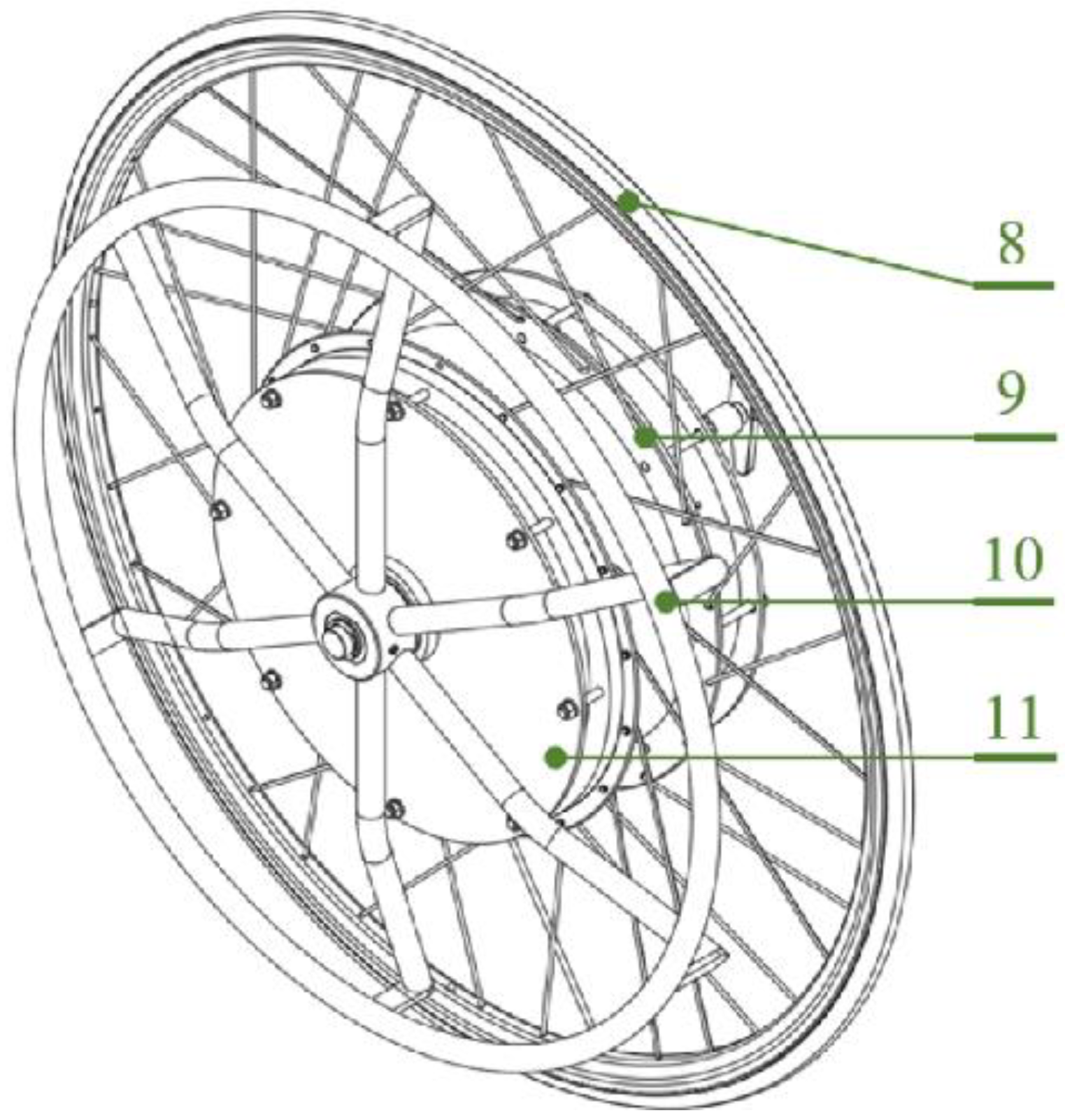
Funding

The study was financed from the means of the National Centre for Research and Development under the LIDER VII Programme, research project No. [LIDER/7/0025/L-7/15/NCBR/2016]. Narodowe Centrum Badań i Rozwoju.

Institutional Review Board Statement

The research and experimental protocols has been positively evaluated by the Bioethical Commission at the Karol Marcinkowski Medical University in Poznan Poland, Resolution No. 1100/16 of 10 November 2016, under the guidance of Prof. MD Chęciński P. for the research team led by Ph.D. Wieczorek B. The data was presented in such a way as to ensure her complete anonymity. The measurement method and data acquisition were carried out in accordance with the directives of the Bioethics Commission at the Karol Marcinkowski Medical University in Poznan Poland, which are in line with the guidelines of the Declarations of Helsinki.

Informed Consent Statement

Informed consent was obtained from all subjects involved in the study.

Data Availability Statement

The data that support the findings of this study are available from the corresponding author upon reasonable request.

Conflicts of Interest

The authors declare no conflict of interest.

References

  1. Young, G.O. Synthetic structure of industrial plastics. In Plastics, 2nd ed.; Peters, J., Ed.; McGraw-Hill: New York, NY, USA, 1964; Volume 3, pp. 15–64. [Google Scholar]
  2. Leving, M.T.; de Groot, S.; Woldring, F.A.; Tepper, M.; Vegter, R.J.; van der Woude, L.H. Motor learning outcomes of handrim wheelchair propulsion during active spinal cord injury rehabilitation in comparison with experienced wheelchair users. Disabil. Rehabil. 2019, 43, 1429–1442. [Google Scholar] [CrossRef] [PubMed] [Green Version]
  3. Levy, C.E.; Buman, M.P.; Chow, J.W.; Tillman, M.D.; Fournier, K.A.; Giacobbi, P., Jr. Use of Power Assist-Wheels Results in Increased Distance Traveled Compared to Conventional Manual Wheeling. Am. J. Phys. Med. Rehabil. Assoc. Acad. Physiatr. 2010, 89, 625–634. [Google Scholar] [CrossRef] [Green Version]
  4. Kloosterman, M.G.; Snoek, G.J.; van der Woude, L.H.; Buurke, J.H.; Rietman, J.S. A systematic review on the pros and cons of using a pushrim-activated power-assisted wheelchair. Clin. Rehabil. 2013, 27, 299–313. [Google Scholar] [CrossRef] [PubMed]
  5. Waluś, K.J. The intensity of the acceleration and deceleration of a passenger car on a road surface covered with fresh snow. Proc. Eng. 2016, 136, 187–192. [Google Scholar] [CrossRef] [Green Version]
  6. Sawicki, P.; Waluś, K.J.; Warguła, Ł. The Comparative Analysis of the Rolling Resistance Coefficients Depending on the Type of Surface—Experimental Research. In Transport Means 2018, Proceedings of the 22nd International Scientific Conference, Trakai, Lithuania, 3–5 October 2018; Kaunas University of Technology: Trakai, Lithuania, 2018; pp. 434–441. [Google Scholar]
  7. Wieczorek, B.; Warguła, Ł.; Rybarczyk, D. Impact of a Hybrid Assisted Wheelchair Propulsion System on Motion Kinematics during Climbing up a Slope. Appl. Sci. 2020, 10, 1025. [Google Scholar] [CrossRef] [Green Version]
  8. Wargua, Ł.; Kukla, M.; Wieczorek, B. The impact of wheelchairs driving support systems on the rolling resistance coefficient. IOP Conf. Ser. Mater. Sci. Eng. 2020, 776, 0120761. [Google Scholar] [CrossRef]
  9. Becker, M. Suspension system for an all-terrain wheelchair. In Proceedings of the RESNA 2000 Annual Conference: Technology for the New Millennium, Orlando, FL, USA, 28 June–2 July 2000; RESNA: Arlington, VA, USA, 2000; p. 462. [Google Scholar]
  10. Sundaram, S.A.; Wang, H.; Ding, D.; Cooper, R.A. Step-climbing power wheelchairs: A literature review. Top. Spinal Cord. Inj. Rehabil. 2017, 23, 98–109. [Google Scholar] [CrossRef] [Green Version]
  11. Riascos, L.A. A low cost stair climbing wheelchair. In Proceedings of the 2015 IEEE 24th International Symposium on Industrial Electronics (ISIE), Buzios, Brazil, 3–5 June 2015; pp. 627–632. [Google Scholar] [CrossRef]
  12. Quaglia, G.; Franco, W.; Oderio, R. Wheelchair. q, a mechanical concept for a stair climbing wheelchair. In Proceedings of the 2009 IEEE International Conference on Robotics and Biomimetics (ROBIO), Guilin, China, 19–23 December 2009; pp. 800–805. [Google Scholar] [CrossRef]
  13. Attali, X.; Pelisse, F. Looking back on the evolution of electric wheelchairs. Med. Eng. Phys. 2001, 23, 735–743. [Google Scholar] [CrossRef]
  14. De Souza, L.H.; Frank, A.O. Problematic clinical features of powered wheelchair users with severely disabling multiple sclerosis. Disabil. Rehabil. 2015, 37, 990–996. [Google Scholar] [CrossRef] [Green Version]
  15. Giacobbi, P.R., Jr.; Levy, C.E.; Dietrich, F.D.; Winkler, S.H.; Tillman, M.D.; Chow, J.W. Wheelchair users’ perceptions of and experiences with power assist wheels. Am. J. Phys. Med. Rehabil. 2010, 89, 225–234. [Google Scholar] [CrossRef]
  16. Kloosterman, M.G.; Eising, H.; Schaake, L.; Buurke, J.H.; Rietman, J.S. Comparison of shoulder load during power-assisted and purely hand-rim wheelchair propulsion. Clin. Biomech. 2012, 27, 428–435. [Google Scholar] [CrossRef] [PubMed]
  17. Kraaijenbrink, C.; Vegter, R.; de Groot, S.; Arnet, U.; Valent, L.; Verellen, J.; van Breukelen, K.; Hettinga, F.; Perret, C.; Abel, T.; et al. Biophysical aspects of handcycling performance in rehabilitation, daily life and recreational sports; a narrative review. Disabil. Rehabil. 2020, 43, 3461–3475. [Google Scholar] [CrossRef]
  18. Andrew, O.F.; de Souza, L.H. Clinical features of children and adults with a muscular dystrophy using powered indoor/outdoor wheelchairs: Disease features, comorbidities and complications of disability. Disabil. Rehabil. 2018, 40, 1007–1013. [Google Scholar] [CrossRef] [Green Version]
  19. Wieczorek, B.; Zabłocki, M. Dźwigniowy System Napędowy Wózka Inwalidzkiego [Leveraged Wheelchair Drive System, Original Text in Polish]. Poland Patent PL223141B1, 7 July 2014. [Google Scholar]
  20. Korpi, E. Leveraged Hand Propeller for a Wheel Chair with Brake. U.S. Patent 5,232,236, 2 April 1992. [Google Scholar]
  21. Schaeffer, J.E.; Schaeffer, J.E. Wheelchair. U.S. Patent 6,715,780B2, 15 October 2001. [Google Scholar]
  22. Gabryelski, J.; Kurczewski, P.; Sydor, M.; Szperling, A.; Torzyński, D.; Zabłocki, M. Development of Transport for Disabled People on the Example of Wheelchair Propulsion with Cam-Thread Drive. Energies 2021, 14, 8137. [Google Scholar] [CrossRef]
  23. Bragança, S.; Castellucci, I.; Gill, S.; Matthias, P.; Carvalho, M.; Arezes, P. Insights on the apparel needs and limitations for athletes with disabilities: The design of wheelchair rugby sports-wear. Appl. Ergon. 2018, 67, 9–25. [Google Scholar] [CrossRef]
  24. De Groot, S.; Bos, F.; Koopman, J.; Hoekstra, A.E.; Vegter, R.J. The effect of a novel square-profile hand rim on propulsion technique of wheelchair tennis players. App. Erg. 2018, 71, 38–44. [Google Scholar] [CrossRef] [PubMed]
  25. Mason, B.S.; van der Woude, L.H.V.; Goosey-Tolfrey, V.L. The Ergonomics of Wheelchair Configuration for Optimal Performance in the Wheelchair Court Sports. Sports Med. 2012, 43, 23–28. [Google Scholar] [CrossRef] [PubMed] [Green Version]
  26. Shepherd, J.B.; James, D.A.; Espinosa, H.G.; Thiel, D.V.; Rowlands, D.D. A Literature Review Informing an Operational Guideline for Inertial Sensor Propulsion Measurement in Wheelchair Court Sports. Sports 2018, 6, 34. [Google Scholar] [CrossRef]
  27. Perret, C. Elite-adapted wheelchair sports performance: A systematic review. Disabil. Rehabil. 2015, 39, 164–172. [Google Scholar] [CrossRef]
  28. Van der Woude, L.H.V.; Janssen, T.W.; Veeger, D. 3rd International Congress ‘Restoration of (wheeled) mobility in SCI rehabilitation: State of the art III’: Its background. Technol. Disabil. 2005, 17, 55–61. [Google Scholar] [CrossRef] [Green Version]
  29. Boninger, M.L.; Cooper, R.A.; Fitzgerald, S.G.; Lin, J.; Cooper, R.; Dicianno, B.; Liu, B. Investigating neck pain in wheelchair users. Am. J. Phys. Med. Rehabil. 2003, 82, 197–202. [Google Scholar] [CrossRef]
  30. Van der Woude, L.H.V.; Veeger, D. Ergonomics of Wheelchair Design: A Prerequisite for Optimum Wheeling Conditions. Adapt. Phys. Activ. Q. 1989, 6, 109–132. [Google Scholar] [CrossRef]
  31. Kukla, M.; Wieczorek, B.; Warguła, Ł. Development of methods for performing the maximum voluntary contraction (MVC) test. MATEC Web Conf. 2018, 157, 050151. [Google Scholar] [CrossRef] [Green Version]
  32. Seniam [Internet]. Available online: http://www.seniam.org/ (accessed on 1 January 2020).
  33. Konrad, P. The ABC of EMG: A Practical Introduction to Kinesiological Electromyography, 1st ed.; Noraxon USA, Inc.: Scottsdale, AZ, USA, 2005; ISBN 0-9771622-1-4. [Google Scholar]
  34. Kukla, M. Analysis and evaluation of muscular effort during wheelchair propulsion based on EMG measurements. In Research on the Biomechanics of Manual Wheelchair Drive for Innovative Manual and Hybrid Drives, 1st ed.; Wieczorek, B., Ed.; Publishing House of Kazimierz Pułaski University of Technology and Humanities: Radom, Poland, 2019; Volume 1, pp. 65–74. [Google Scholar]
  35. Lebedev, I.; Erashov, A.; Shabanova, A. Accurate Autonomous UAV Landing Using Vision-Based Detection of ArUco-Marker. In Interactive Collaborative Robotics, Proceedings of the International Conference on Interactive Collaborative Robotics, St Petersburg, Russia, 7–9 October 2020; Springer: Cham, Switzerland, 2020; pp. 179–188. [Google Scholar] [CrossRef]
  36. Lou, S.; Jiang, X.; Scott, P.J. Application of the morphological alpha shape method to the extraction of topographical features from engineering surfaces. Measurement 2013, 46, 1002–1008. [Google Scholar] [CrossRef] [Green Version]
  37. Lafta, H.A.; Guppy, R.; Whatling, G.; Holt, C. Impact of rear wheel axle position on upper limb kinematics and electromyography during manual wheelchair use. Int. Biomech. 2018, 5, 17–29. [Google Scholar] [CrossRef] [Green Version]
  38. Yang, Y.S.; Koontz, A.M.; Yeh, S.J.; Chang, J.J. Effect of backrest height on wheelchair propulsion biomechanics for level and uphill conditions. Arch. Phys. Med. Rehabil. 2012, 93, 654–659. [Google Scholar] [CrossRef]
  39. Qi, L.; Wakeling, J.; Grange, S.; Ferguson-Pell, M. Coordination patterns of shoulder muscles during level-ground and incline wheelchair propulsion. J. Rehabil. Res. Dev. 2013, 50, 651–662. [Google Scholar] [CrossRef] [PubMed]
  40. Wieczorek, B.; Kukla, M.; Wieczorek, R. Multi-gear hub prototype for manual wheelchairs-design and operation. AUTOBUSY Tech. Eksploat. Syst. Transp. 2018, 19, 825–830. [Google Scholar] [CrossRef] [Green Version]
  41. Lee, S.Y.; Lee, S.K.; Ahn, S.H. Effect of various wheelchair handle grip directions on muscle activities of upper body of assistant during movement on ascending and descending ramps. J. Phys. Ther. Sci. 2017, 29, 2090–2093. [Google Scholar] [CrossRef] [PubMed] [Green Version]
  42. Morrow, M.M.; Kaufman, K.R.; An, K.N. Shoulder model validation and joint contact forces during wheelchair activities. J. Biomech. 2010, 43, 2487–2492. [Google Scholar] [CrossRef] [Green Version]
  43. Lafta, H.A. Analysis of Upper Body Biomechanics and Control In Manual Wheelchair Users. Ph.D. Thesis, Cardiff University, Cardiff, UK, 2018. [Google Scholar]
  44. Wieczorek, B.; Kukla, M. Effects of the performance parameters of a wheelchair on the changes in the position of the centre of gravity of the human body in dynamic condition. PLoS ONE 2019, 14, e0226013. [Google Scholar] [CrossRef] [PubMed]
  45. Wieczorek, B.; Kukla, M. Biomechanical Relationships Between Manual Wheelchair Steering and the Position of the Human Body’s Center of Gravity. J. Biomech. Eng. 2020, 142, 081006. [Google Scholar] [CrossRef] [PubMed]
  46. Brubaker, C.E. Wheelchair prescription: An analysis of factors that affect mobility and performance. J. Rehabil. Res. Dev. 1986, 23, 19–26. [Google Scholar]
  47. Wieczorek, B.; Górecki, J.; Kukla, M.; Wojtokowiak, D. The analytical method of determining the center of gravity of a person propelling a manual wheelchair. Procedia Eng. 2017, 177, 405–410. [Google Scholar] [CrossRef]
  48. Lalumiere, M.; Gagnon, D.H.; Hassan, J.; Desroches, G.; Zory, R.; Pradon, D. Ascending curbs of progressively higher height increases forward trunk flexion along with upper extremity mechanical and muscular demands in manual wheelchair users with a spinal cord injury. J. Electromyogr. Kinesiol. 2013, 23, 1434–1445. [Google Scholar] [CrossRef]
  49. Van Drongelen, S.; van der Woude, L.H.V.; Janssen, T.W.; Angenot, E.L.; Chadwick, E.K.; Veeger, D.H. Mechanical load on the upper extremity during wheelchair activities. Arch. Phys. Med. Rehabil. 2005, 86, 1214–1220. [Google Scholar] [CrossRef] [PubMed] [Green Version]
  50. Arnet, U.; van Drongelen, S.; Scheel-Sailer, A.; van der Woude, L.H.V.; Veeger, D.H. Shoulder load during synchronous handcycling and handrim wheelchair propulsion in persons with paraplegia. J. Rehabil. Med. 2012, 44, 222–228. [Google Scholar] [CrossRef] [Green Version]
  51. Boninger, M.L.; Souza, A.L.; Cooper, R.A.; Fitzgerald, S.G.; Koontz, A.M.; Fay, B.T. Propulsion patterns and pushrim biomechanics in manual wheelchair propulsion. Arch. Phys. Med. Rehabil. 2002, 83, 718–723. [Google Scholar] [CrossRef]
  52. Koontz, A.M.; Roche, B.M.; Collinger, J.L.; Cooper, R.A.; Boninger, M.L. Manual wheelchair propulsion patterns on natural surfaces during start-up propulsion. Arch. Phys. Med. Rehabil. 2009, 90, 1916–1923. [Google Scholar] [CrossRef]
  53. Miyazaki, Y.; Iida, K.; Nakashima, M.; Maruyama, T.; Yamanobe, K. Measurement of pushrim forces during racing wheelchair propulsion using a novel attachable force sensor system. Proc. Inst. Mech. Eng. Part P J. Sports Eng. Technol. 2020, 1–10. [Google Scholar]
  54. Qi, L.; Guan, S.; Zhang, L.; Liu, H.L.; Sun, C.K.; Ferguson-Pell, M. The effect of fatigue on wheelchair users’ upper limb muscle coordination patterns in time-frequency and principal component analysis. IEEE Trans. Neural Syst. Rehabil. Eng. 2021, 29, 2096–2102. [Google Scholar] [CrossRef] [PubMed]
  55. McLaurin, C.A.; Brubaker, C.E. Biomechanics and the wheelchair. Prosthet. Orthot. Int. 1991, 15, 24–37. [Google Scholar] [CrossRef] [Green Version]
  56. Warguła, Ł.; Kukla, M.; Yurchenko, V.; Kukesheva, A. Analysis of the usability of rolling resistance measurement methods to study the mechanisms of some wheelchairs. IOP Conf. Ser. Mater. Sci. Eng. 2021, 1199, 012063. [Google Scholar] [CrossRef]
  57. Warguła, Ł.; Marciniak, A. The Symmetry of the Muscle Tension Signal in the Upper Limbs When Propelling a Wheelchair and Innovative Control Systems for Propulsion System Gear Ratio or Propulsion Torque: A Pilot Study. Symmetry 2022, 14, 1002. [Google Scholar] [CrossRef]
  58. Kukla, M.; Maliga, W. Symmetry Analysis of Manual Wheelchair Propulsion Using Motion Capture Techniques. Symmetry 2022, 14, 1164. [Google Scholar] [CrossRef]
  59. Soltau, S.L.; Slowik, J.S.; Requejo, P.S.; Mulroy, S.J.; Neptune, R.R. An investigation of bilateral symmetry during manual wheelchair propulsion. Front. Bioeng. Biotechnol. 2015, 3, 86. [Google Scholar] [CrossRef]
  60. Koontz, A.M.; Cooper, R.A.; Boninger, M.L. An autoregressive modeling approach to analyzing wheelchair propulsion forces. Med. Eng. Phys. 2001, 23, 285–291. [Google Scholar] [CrossRef]
  61. Schnorenberg, A.J.; Slavens, B.A.; Wang, M.; Vogel, L.C.; Smith, P.A.; Harris, G.F. Biomechanical model for evaluation of pediatric upper extremity joint dynamics during wheelchair mobility. J. Biomech. 2014, 47, 269–276. [Google Scholar] [CrossRef] [Green Version]
  62. Mercer, J.L.; Boninger, M.; Koontz, A.; Ren, D.; Dyson-Hudson, T.; Cooper, R. Shoulder joint kinetics and pathology in manual wheelchair users. Clin. Biomech. 2006, 21, 781–789. [Google Scholar] [CrossRef]
Figure 1. View of the assembled system: 8—tire, 9—system of spokes mounted to the hub flange, 10—handrims and 11—internal gear hub.
Applsci 12 07737 g001
Figure 2. View of the diagram of the constructed planetary gear: (a) view of the internal gear hub and methods of coupling the planetary gear; 1—splined disc, 2—splined ring, (b) view of the bearing system of the carrier inside the planetary gear; 3—carrier, 4—sun gear, 5—radial bearing, 6—axial bearing and 7—ring gear (internal teeth).
Applsci 12 07737 g002
Figure 3. Diagrams of planetary gears for different ratios: (a) first gear, (b) second gear, (c) third gear; 12—internal teeth, 13—planetary gear, 14—sun gear, 15—carrier, nin—input rotational speed and nout—output rotational speed.
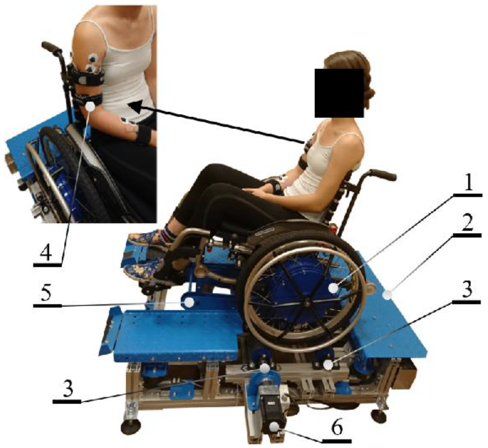
Applsci 12 07737 g003
Figure 4. View of the dynamometer, the examined wheelchair with the participant and the arrangement of electrodes; 1—planetary gear integrated in the hub of a larger wheel, 2—test stand (wheelchair dynamometer), 3—support rollers for the propelled wheel, 4—measuring electrodes, 5—mounting arm (enables changing the angle of inclination of the wheelchair) and 6—servo drive.
Applsci 12 07737 g004
Figure 5. Diagram of carried out experiments; A1—patient preparation, A2—normalization, A3—placing on the stand, B1—test start, B2—break, B3—test variant change and B4—test end.
Applsci 12 07737 g005
Figure 6. Markers used for motion capture (a) placement on the test participant and (b) dimensions.
Applsci 12 07737 g006
Figure 7. Geometric interpretation of the kinematic parameters of the upper limb segments during measurements with the use of motion capture.
Applsci 12 07737 g007
Figure 8. Average values of the area under the diagram (SA) for measurement tests s2, k1-3 and p1-3 for the muscle: extensor carpi radialis longus (D); error bars are ± standard deviation.
Applsci 12 07737 g008
Figure 9. Average values of the area under the diagram (SA) for measurement tests s2, k1 and p1-3 for the posterior part of the deltoid muscle (B); error bars are ± standard deviation, rectangles are ± standard error.
Applsci 12 07737 g009
Figure 10. The average EMG signal amplitude values ( M V C M A X ) for all propulsion cycles for measurement tests s2; error bars are ± standard deviation; designations: p1–3—the gear ratio, k1–3—the inclination angle, A–D—the type of muscle (as specified in the Test Conditions and Statistical Analysis paragraph).
Applsci 12 07737 g010
Figure 11. The displacement of individual markers for a constant gear ratio and a variable inclination angle of the wheelchair.
Applsci 12 07737 g011
Figure 12. The displacement of individual markers for a constant inclination angle of the wheelchair and a variable gear ratio.
Applsci 12 07737 g012
Figure 13. Designated values: (a) total angle of rotation φ of wrist marker (ID1) and (b) total displacement s of wrist marker (ID1).
Applsci 12 07737 g013
Figure 14. Designated values (a) mean value of L and H and (b) mean value of surface area A I D 1 .
Applsci 12 07737 g014
Table 1. Variants, markings and input values used in experiments.
Gear RatioSeries NumberWheelchair Inclination AngleMuscle
p1 = 1.96s1k1 = 0°Deltoid muscle anterior (A) and posterior (B)
p2 = 1s2k2 = 1.5°Triceps brachii (C)
p3 = 0.51s3k3 = 5.4°Extensor carpi radialis longus (D)
Table 2. The average values and the statistical data of the area under the diagram (SA) for the individual propulsion cycles; x ¯ —arithmetic mean, σ —standard deviation of the arithmetic mean, σ x ¯ —standard error, p v a l —test probability for the Anderson–Darling test; muscle markings: Deltoid muscle anterior (A) and posterior (B), Triceps brachii (C), Extensor carpi radialis longus (D); markings of the angles of the erection of the wheelchair: k1 = 0°, k2 = 1.5° and k1 = 5.4°; markings of experiment series: s1, s2 and s3; markings of the propulsion system gear ratios: p1 = 1.96, p2 = 1 and p3 = 0.51.
s1 As1 Bs1 Cs1 D
p1p2p3p1p2p3p1p2p3p1p2p3
k1 x ¯ [s·%]23.3321.5119.0332.5030.3429.9421.2815.4614.596.084.553.17
σ [s·%]2.742.000.991.602.091.991.441.170.990.330.470.14
σ x ¯ [s·%]0.610.450.220.360.470.440.320.260.220.070.110.03
p v a l 0.090.180.260.640.170.180.170.650.100.090.460.35
k2 x ¯ [s·%]23.5723.4422.3736.8830.8530.3924.1119.4315.2010.645.983.62
σ [s·%]3.101.841.393.412.731.871.951.440.880.850.730.17
σ x ¯ [s·%]0.690.410.310.760.610.420.440.320.200.190.160.04
p v a l 0.500.060.090.590.180.190.530.120.380.530.520.16
k3 x ¯ [s·%]31.2027.9524.5748.9439.6135.9436.8827.9621.6120.506.455.46
σ [s·%]2.371.481.675.323.463.182.963.061.311.530.480.54
σ x ¯ [s·%]0.530.370.331.190.770.710.660.680.290.340.110.12
p v a l 0.090.290.090.080.090.260.130.110.400.140.250.14
s2 As2 Bs2 Cs2 D
p1p2p3p1p2p3p1p2p3p1p2p3
k1 x ¯ [s·%]27.4419.1419.0330.5127.5625.6020.4915.6113.239.143.552.96
σ [s·%]1.221.180.992.280.991.511.030.760.700.970.290.19
σ x ¯ [s·%]0.270.260.220.510.220.340.390.240.180.220.060.04
p v a l 0.450.170.260.920.370.770.600.540.230.570.690.77
k2 x ¯ [s·%]28.4021.1220.5147.0927.7326.4937.3818.5913.939.274.043.62
σ [s·%]2.261.330.974.221.791.342.551.550.900.790.300.25
σ x ¯ [s·%]0.510.300.220.940.400.300.910.180.180.180.070.06
p v a l 0.320.470.750.330.770.280.110.100.090.160.190.10
k3 x ¯ [s·%]30.9025.7724.7053.4038.9933.8550.5830.4027.879.696.505.28
σ [s·%]2.471.311.924.402.892.207.943.311.560.740.400.49
σ x ¯ [s·%]0.550.290.430.980.650.490.940.680.370.160.090.11
p v a l 0.470.820.490.500.700.130.120.210.550.600.220.05
s3 As3 Bs3 Cs3 D
p1p2p3p1p2p3p1p2p3p1p2p3
k1 x ¯ [s·%]20.5018.6318.4128.6626.9525.7620.4915.6113.235.204.153.16
σ [s·%]1.030.841.161.892.092.441.030.760.700.430.190.22
σ x ¯ [s·%]0.230.190.260.420.470.550.230.170.160.100.040.05
p v a l 0.870.830.910.180.430.360.600.540.230.300.690.65
k2 x ¯ [s·%]25.1224.6918.7847.7744.1927.5537.3818.5913.938.775.373.71
σ [s·%]1.401.491.453.493.401.532.551.550.901.230.750.27
σ x ¯ [s·%]0.310.330.320.760.780.340.570.350.200.280.170.06
p v a l 0.870.510.270.060.720.120.110.100.090.070.070.11
k3 x ¯ [s·%]34.8931.9224.8954.1953.9039.7950.5830.4027.8710.058.316.79
σ [s·%]2.501.981.104.825.034.797.943.311.560.700.600.63
σ x ¯ [s·%]0.560.250.441.081.121.071.770.740.350.160.130.14
p v a l 0.670.910.890.280.120.310.120.210.550.290.130.09
Table 3. The statistical data of the analysis of variance (ANOVA); F —F test value, p v a l —test probability of ANOVA analysis, Deltoid muscle anterior (A) and posterior (B), Triceps brachii (C), Extensor carpi radialis longus (D); markings of the angles of erection of the wheelchair: k1 = 0°, k2 = 1.5° and k1 = 5.4°; markings of experiment series: s1, s2 and s3; markings of the propulsion system gear ratios: p1 = 1.96, p2 = 1 and p3 = 0.51.
F p v a l F p v a l F p v a l F p v a l
s1 As1 Bs1 Cs1 D
p1-3166.078.46 × 1041206.212.69 × 10−46665.362.10 × 10−811192.563.74 × 10−101
k1-339.627.29 × 10−1596.997.02 × 10−29472.892.09 × 10−702350.684.16 × 10−125
Interaction18.341.48 × 10−1215.844.74 × 10−1131.421.29 × 10−19540.837.04 × 10−96
s2 As2 Bs2 Cs2 D
p1-3170.931.64 × 10−41429.841.99 × 10−67667.011.74 × 10−81201.491.09 × 10−45
k1-3404.841.4 × 10−65539.421.38 × 10−74830.898.42 × 10−891673.815.09 × 10−113
Interaction5.420.00039371.401.85 × 10−35111.281.59 × 10−4629.071.93 × 10−18
s3 As3 Bs3 Cs3 D
p1-3877.561.2 × 10−90599.865.16 × 10−78621.093.79 × 10−79654.926.96 × 10−81
k1-3135.904.68 × 10−36216.881.25 × 10−47551.692.61 × 10−75443.292.20 × 10−68
Interaction106.422.44 × 10−4542.021.65 × 10−2453.294.26 × 10−2931.778.65 × 10−20
Table 4. The average values and the statistical data on the average amplitude of the EMG signal values ( M V C M A X ) for the individual propulsion cycles; x ¯ —the arithmetic mean, σ —the standard deviation of the arithmetic mean; the muscle markings: Deltoid muscle anterior (A) and posterior (B), Triceps brachii (C), Extensor carpi radialis longus (D); markings of experiment series: s1, s2 and s3; markings of the propulsion system gear ratios: p1 = 1.96, p2 = 1 and p3 = 0.51.
s1 As1 Bs1 Cs1 D
p1p2p3p1p2p3p1p2p3p1p2p3
k1 x ¯ [%]25.3924.0023.4839.1237.3136.7331.2324.5023.2711.566.274.42
σ [%]2.502.282.023.124.012.691.333.022.611.200.880.23
k2 x ¯ [%]30.0326.4126.4842.6041.7939.1937.6727.8723.4119.5010.244.54
σ [%]2.812.011.704.982.524.395.312.893.112.481.580.54
k3 x ¯ [%]45.3433.3129.1582.8047.1346.6868.5652.0035.7931.2610.928.19
σ [%]3.232.052.7314.975.325.428.018.533.154.171.201.06
s2 As2 Bs2 Cs2 D
p1p2p3p1p2p3p1p2p3p1p2p3
k1 x ¯ [%]45.0622.3921.5941.0739.8535.1229.5823.1821.2116.486.274.93
σ [%]5.961.681.683.682.732.392.002.832.271.840.670.61
k2 x ¯ [%]47.4725.4024.9871.9341.0138.3966.4624.9324.0017.756.905.21
σ [%]3.541.771.589.723.521.778.722.511.812.610.510.48
k3 [%]57.4533.0531.73104.2456.4850.49106.3357.2441.0319.4011.579.09
σ [%]5.293.303.259.457.235.3016.126.734.481.951.231.64
s3 As3 Bs3 Cs3 D
p1p2p3p1p2p3p1p2p3p1p2p3
k1 x ¯ [%]29.7726.1324.1344.9643.4242.1637.7729.8025.2310.877.985.87
[%]2.592.562.083.974.233.322.392.932.761.620.830.86
k2 x ¯ [%]46.9437.6225.0284.0559.6645.8080.8340.3828.5015.9212.795.99
σ [%]5.093.212.4210.835.973.8510.105.252.782.643.180.83
k3 x ¯ [%]63.4039.8951.92119.4276.8962.19121.1066.3161.2020.6115.1315.03
σ [%]5.523.883.6813.288.126.0315.667.933.712.151.441.65
Table 5. Mean values of the displacement s and the angle covered by individual markers φ ; σ s —standard deviation of the arithmetic mean of the marker’s displacement and σ φ —standard deviation of the arithmetic mean of the angle covered by the marker.
ID1ID3ID5
s   [ mm ] σ s   [ mm ] φ   [ ° ] σ φ   [ ° ] s   [ mm ] σ s   [ mm ] φ   [ ° ] σ φ   [ ° ] s   [ mm ] σ s   [ mm ] φ   [ ° ] σ φ   [ ° ]
k1p1push728.067.660.13.7611.341.628.01.3375.220.29.70.8
return658.925.668.40.6533.240.823.81.8261.411.76.10.2
p2push773.719.162.93.6614.116.229.51.3358.49.210.10.8
return707.659.769.63.6564.473.026.41.5327.364.99.00.5
p3push630.88.248.02.5503.015.224.71.1408.021.612.91.5
return565.933.955.55.9516.410.524.93.4335.99.013.21.4
k2p1push815.994.573.34.0689.518.137.90.8380.99.612.01.1
return787.224.370.32.1646.718.927.91.8340.335.314.41.5
p2push777.947.771.27.2633.821.533.81.1392.86.315.61.0
return743.725.174.95.0586.849.433.21.8316.19.112.62.5
p3push625.223.450.214.9590.119.527.71.9453.331.714.84.8
return591.446.558.03.0448.035.029.81.8342.621.416.61.9
k3p1push883.324.183.32.0697.249.040.31.4446.848.320.00.4
return903.224.882.03.6756.618.535.92.9369.020.216.11.6
p2push816.38.678.41.8667.143.536.61.4401.510.817.10.9
return776.230.680.93.1614.427.933.61.8336.722.722.52.0
p3push762.128.166.28.5650.928.536.13.0479.84.219.20.8
return726.869.869.64.4618.968.732.64.8358.870.316.30.5
Table 6. Mean values of surface areas A I D and corresponding lengths L and widths H of the designated shapes for all of the markers; σ L —standard deviation of length, σ H —standard deviation of the height and σ A I D —standard deviation of surface area.
Wrist ID1
L   [ mm ] H   [ mm ] A I D   [ m 2 ] σ L   [ mm ] σ H   [ mm ] σ A I D   [ m 2 ]
k1p1585.26213.090.020820.7512.660.0007
p2623.55199.970.026622.2117.960.0007
p3536.18194.330.019783.6319.620.0051
k2p1703.92195.650.032421.111.680.0023
p2659.20191.640.030922.7219.660.0054
p3517.41120.850.020419.636.440.0027
k3p1696.84162.230.03148.5012.300.0105
p2632.86141.420.024034.1514.400.0027
p3640.89149.320.022531.3310.920.0025
Elbow ID3
k1p1528.47253.250.045334.3114.230.0052
p2514.40240.350.054818.8320.260.0020
p3473.46222.660.032935.1810.870.0083
k2p1503.50215.900.048617.822.240.0021
p2488.91208.720.041028.9317.870.0049
p3408.18152.260.037863.078.390.0036
k3p1530.65180.270.05049.486.900.0066
p2488.51171.920.044438.866.590.0081
p3520.38163.770.045731.956.520.0040
Shoulder ID5
k1p1214.30137.460.013926.7814.560.0023
p2169.96131.140.011720.6411.220.0010
p3263.54142.300.014822.775.560.0007
k2p1248.72136.570.01754.552.530.0001
p2236.59139.180.012043.6513.840.0045
p3268.57100.060.017016.7612.110.0022
k3p1267.42121.340.017747.3916.210.0045
p2216.70102.970.015126.0412.550.0024
p3237.46105.860.01749.124.940.0011
Publisher’s Note: MDPI stays neutral with regard to jurisdictional claims in published maps and institutional affiliations.

