Brief Report

High-Temperature Annealing Effects on Atomically Thin Tungsten Diselenide Field-Effect Transistor

by
Muhammad Atif Khan
,
Muhammad Qasim Mehmood
and
Yehia Massoud
*
Innovative Technologies Laboratories (ITL), King Abdullah University of Science and Technology (KAUST), Thuwal 23955, Saudi Arabia
*
Author to whom correspondence should be addressed.
Appl. Sci. 2022, 12(16), 8119; https://doi.org/10.3390/app12168119
Submission received: 22 July 2022 / Revised: 11 August 2022 / Accepted: 12 August 2022 / Published: 13 August 2022
(This article belongs to the Topic Advances and Applications of 2D Materials, 2nd Volume)

Abstract

:
Two-dimensional (2D) material-based devices are expected to operate under high temperatures induced by Joule heating and environmental conditions when integrated into compact integrated circuits for practical applications. However, the behavior of these materials at high operating temperatures is obscure as most studies emphasize only room temperature or low-temperature operation. Here, the high-temperature electrical response of the tungsten diselenide (WSe2) field-effect transistor was studied. It is revealed that 350 K is the optimal annealing temperature for the WSe2 transistor, and annealing at this temperature improves on-current, field-effect mobility and on/off ratio around three times. Annealing beyond this temperature (360 K to 670 K) adversely affects the device performance attributed to the partial oxidation of WSe2 at higher temperatures. An increase in hysteresis also confirms the formation of new traps as the device is annealed beyond 350 K. These findings explicate the thermal stability of WSe2 and can help design 2D materials-based durable devices for high-temperature practical applications.

1. Introduction

Since the invention of the transistor in 1947, silicon has become the material of choice for electronics [1,2,3,4] and photonics applications [5,6,7,8]. For the last few decades, enormous efforts have been made by the scientific community to find an alternative to silicon as a material of choice for future electronics [9,10,11]. It has been long appreciated that carbon nanotubes (CNTs) possess the required potential to be an ideal electronics material [12,13,14,15,16]. However, the challenges that arise from the non-uniform and imperfect growth of CNTs could not be resolved [12]. Since the discovery of graphene in 2004, 2D materials have emerged as a strong candidate for future high-speed and low-power electronics [17,18,19,20]. Two-dimensional materials possess several intrinsic properties like quantum confinement, a reasonable large bandgap, ease of fabrication, strong light–matter interaction, ability to form heterostructures and strong gate modulation, making them a suitable material for future electronics as well as photonics applications [21,22,23,24]. Among the 2D materials family, transition metal dichalcogenides (TMDs) are particularly of interest. WSe2 is a prominent member of TMDs because of its ambipolar behavior, large spin–orbit coupling and optical properties [25]. Studies showed the application of WSe2 not only in electronic applications such as inverters and Schottky diodes [26] but also in photonic applications such as photodetectors, single-photon emitters and light-emitting diodes [27].
Until now, most of the studies have investigated the properties of WSe2 at either room temperature or cryogenic temperatures [28]. While these studies were successful in understanding the intrinsic properties of the materials, there have been very few studies investigating the behavior of the material at high temperatures. For practical applications, 2D materials are expected to operate under high thermal stress caused by Joule heating in integrated circuits or local heating due to incident light in photonic applications [29,30,31]. Further, due to low thermal conductivity and heat capacity as well as high surface area, these materials are expected to endure temperatures higher than bulk materials such as Si and GaAs [32,33,34,35,36]. Therefore, it is essential to test the WSe2 devices at high operating temperatures and monitor their performance under these conditions.
In this work, we designed an experimental setup to investigate the changes in the electrical behavior of the WSe2 device after being exposed to high annealing temperatures. The investigation was carried out using a homemade probe station that can also anneal the devices in a nitrogen environment so that there is no need to take out the device after annealing. The device was annealed to temperatures ranging from 300 K to 670 K (step size: 10 K), and the electrical characterization of the device was performed at 300 K after each cycle of annealing. It was found that 350 K is the optimal annealing temperature for WSe2, which improves the device performance by eliminating the adsorbed species and chemical residue. Annealing at temperatures higher than 350 K adversely affects the device performance. The effects of annealing on the transfer characteristic curve, on/off ratio, field-effect mobility and hysteresis were investigated.

2. Materials and Methods

Figure 1a,c shows the schematic drawing and optical microscope image of the WSe2 device. In order to fabricate this device, thin WSe2 flakes were produced from the bulk WSe2 crystal by the standard exfoliation method using scotch tape. The flakes were then transferred on a silicon substrate capped with 300 nm SiO2. An optical microscope was used to scan the substrate and identify suitable flakes, followed by Raman spectroscopy and atomic force microscopy (AFM). The back gated devices were prepared by electron beam lithography followed by metal deposition in an electron beam evaporation chamber. Electron beam lithography was used to make contact patterns on the selected WSe2 flake. Titanium/gold (Ti/Au) with a thickness of 10/40 nm were chosen as contact materials as Ti forms Ohmic-like contacts with WSe2. The metal deposition was carried out in an electron beam evaporation chamber, followed by the lift-off in acetone.

3. Results and Discussion

Figure 1b illustrates the Raman spectrum of the device taken by a 532 nm laser. The signature WSe2 Raman peaks, E12g and A1g, can be seen at 252 cm−1 and 261cm−1, respectively [37,38]. The presence of these two peaks not only confirms the material to be WSe2 but also indicates that the flake thickness is more than four layers [22,23]. The Rama n spectroscopy was performed after annealing at 673 K as well. The comparison of the Raman spectrum before and after annealing is discussed in the later part. In order to accurately determine the WSe2 thickness, atomic force microscopy (AFM) was carried out. Figure 1d presents the AFM image of the WSe2 flake as well as the line profile between the two points shown in Figure 1d. It can be seen that the flake thickness is 5 nm, which corresponds to eight layers of WSe2.
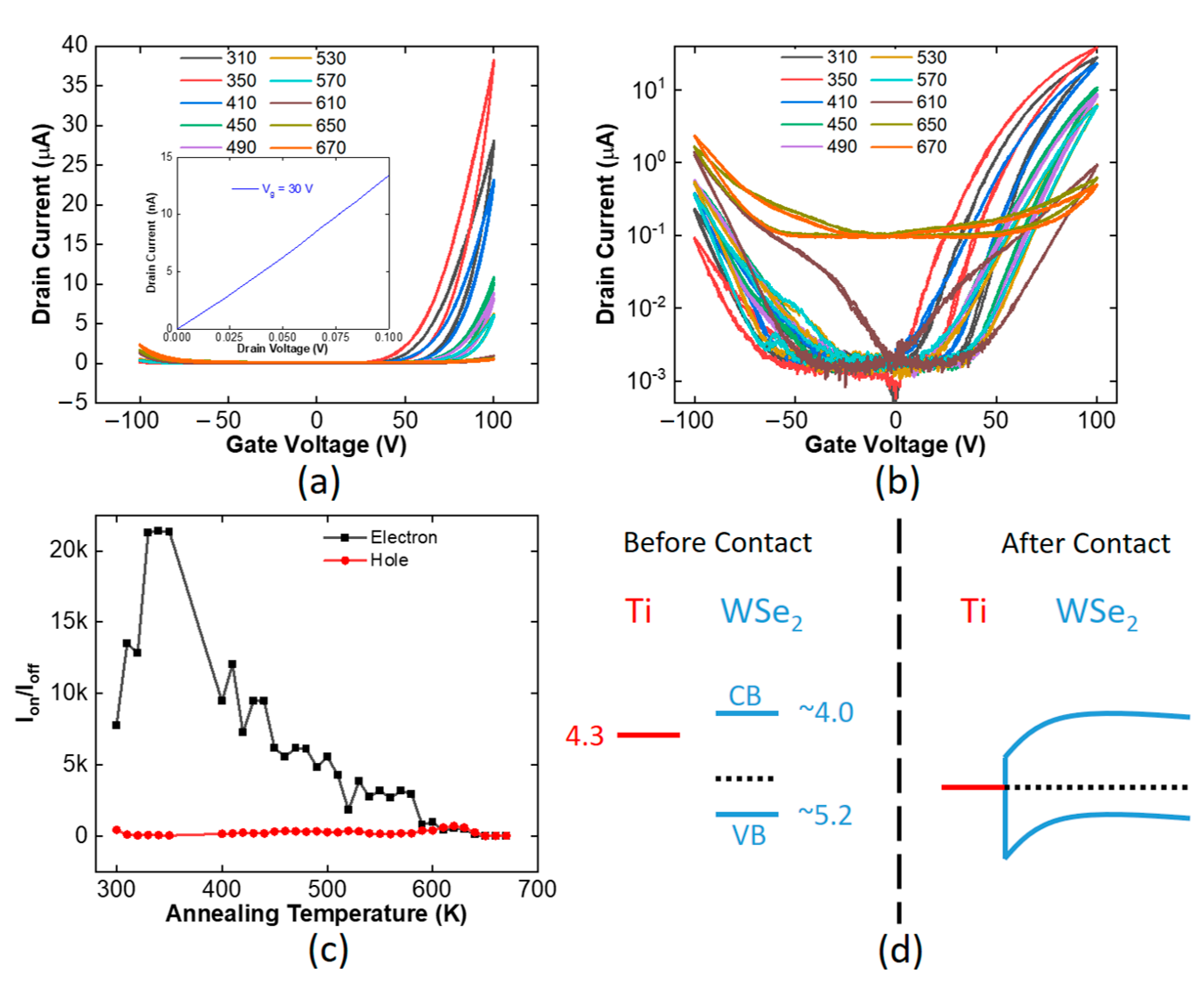
The transfer characteristics curves of the device at a constant source-drain voltage of 1 V measured at 300 K after annealing at different temperatures is shown in Figure 2. The influence of annealing on the device properties was systematically investigated by annealing the device at a target temperature for 30 min in a Nitrogen environment and then measuring its transfer characteristics curve at 300 K. The process was repeated for temperatures ranging from 310 K to 670 K with a step size of 10 K. In Figure 2, however, for better visibility, transfer curves are shown for selected annealing temperatures only. It can be seen that the device exhibits ambipolar behavior with hole-dominated transport for negative gate voltages and electron-dominated transport for positive gate voltages. After annealing at 310 K, the electron current is almost an order of magnitude higher than the hole current. In most studies, WSe2 exhibit p-dominant transport; however, in the present study, n-dominant transport can be attributed to the Ti contacts. As shown in the schematic band diagram in Figure 2d, Ti has a work function of 4.3 eV, which is closer to the conduction band of WSe2 [39,40]. Therefore, Ti can facilitate the injection of electrons in the conduction band of WSe2 by forming good Ohmic-like contacts. At the same time, Ti forms a large Schottky barrier with the valence band of WSe2. This Schottky barrier results in electron transport being more prominent than the hole current. The inset of Figure 2a represents the output curve (IdVd) of the WSe2 device, and Ohmic-like linear characteristics can be seen there.
For the positive gate region (electron transport), as the annealing temperature is increased up to 350 K, an increase in the drain current as well as on/off ratio (ratio of on current to the off current of the device) is observed. As annealing temperature increases from 300 K to 350 K, the on/off ratio increases from 8000 to 22,000, whereas maximum on current increases from 14 μA to 37 μA. This observation of enhanced device performance after annealing is consistent with the previous studies in the literature [41]. The annealing improves the device’s performance by removing the contaminants, adsorbed moisture and chemical residues from the surface of WSe2 [41]. Two-dimensional materials possess a high surface-to-volume ratio and are extremely sensitive to the changes at the interface; therefore, annealing can drastically improve the device’s performance. However, as the annealing temperature is increased beyond 350 K, the device performance gradually deteriorates. Overall, a decrease in device current as well as on/off ratio can be seen when the annealing temperature exceeds 350 K. The maximum current reduces from 37 μA to 1.5 μA, and the on/off ratio reduces from 22,000 to 1000 as the annealing temperature is gradually increased from 350 K to 590 K. Previous studies reported that WSe2 oxidizes to WOx at high temperatures [42,43]. The oxidation of 2D materials differs from bulk materials as these materials show higher reactivity at the edges and defect sites only. The effects of oxidation on the electrical characteristics of the WSe2 device can be seen in this temperature range (350 K to 590 K), where not only the on/off ratio and total current reduced but a decrease in the subthreshold swing can also be observed. It is safe to say that higher thermal and electrical stress has induced structural and chemical changes in the WSe2, which is further explained in the latter part. From 590 K to 670 K, the device behavior changes from semiconducting to fully conducting with very little gate control. The on/off ratio in the region is less than 10, and the off current has increased several orders of magnitude. In order to obtain further insight into the device behavior, we extracted field-effect mobility and hysteresis of the device.
Figure 3 illustrates the field effect mobility as well as hysteresis as a function of annealing temperature. The field-effect mobility was extracted for electrons as well as holes using the following equation:
μ = L W   g m C o x V d
In this equation, L and W are the total channel length and width, respectively, and Cox is the back gate silicon dioxide capacitance per unit area, calculated by Cox = ε0·εr/d. Here, ε0 = 8.85 × 10⁻¹² Fm−1 is the permittivity of free space, and εr = 3.9 is the relative permittivity of SiO2 and d is SiO2 thickness (300 nm). gm is the trans-conductance obtained from the slope of each transfer curve, Vd is the applied drain voltage and μ is the field effect mobility. A similar trend for electron mobility can also be seen in Figure 3, where initially, electron mobility increases from 4 cm2/V·s to 9 cm2/V·s as the annealing temperature is increased from 300 to 350 K. The mobility in 2D materials is limited by the scattering, and an improvement in mobility indicates a reduction in scattering. All the measurements were performed at 300 K, so it was safe to rule out any change in phonon scattering. Therefore, the increase in electron mobility can be attributed to a cleaner WSe2 surface enabled by thermal annealing. As observed previously, in the temperature range of 360 K to 590 K, a consistent drop in electron mobility can be seen. One can also observe three distinct regions in the mobility curve: the mobility increases from 300 K to 350 K and from 350 K to 590 K, mobility gradually reduces from 9 cm2/V.s to 2.5 cm2/V.s and it reaches 0.1 cm2/V.s at 670 K. This trend of mobility and device current reflects that 350 K is the optimal annealing temperature for WSe2. Until this temperature, annealing improves the device’s performance by removing the contaminants, adsorbed moisture and chemical residues from the surface of WSe2 [41]. Beyond 350 K, the high temperature starts to oxidize WSe2 and alter its chemical composition. As WSe2 becomes oxidized to WOx, new traps are created at the WSe2-WOx interface, which results in a reduction in electron mobility [42,43]. The presence of hysteresis in the transfer curve is an indicator of charge traps in a device, so we investigated the hysteresis behavior of our device, as shown in Figure 3b. It is defined as the threshold voltage difference between the forward and reverse gate voltage sweep. Three distinct regions are also visible here; from 300 K to 350 K, hysteresis reduces, indicating the removal of traps and surface contaminants from WSe2. It gradually increases from 350 K to 590 K and increases exponentially from there onwards. Since hysteresis is an indicator of traps, it can be said that as WSe2 becomes oxidized beyond 350 K, new traps are created, which degrade device performance by causing a reduction in electron mobility and on/off ratio. Figure 3c presents the off current as a function of annealing, which remains almost constant except at temperatures beyond 630 K, where chemical changes in WSe2 result in complete loss of gate control. The comparison of Raman (Figure 1d) and AFM measurements (Figure 3d) before and after the annealing give insight into the chemical changes induced by the thermal stress. In the Raman spectrum, the quenching of Raman peaks after annealing points to partial oxidation of WSe2 and the formation of new traps [44]. The average surface roughness before annealing was 320 pm, which was increased to 450 pm after annealing. The increased surface roughness in AFM measurement also corresponds to the formation of new traps. The observations such as quenching in the Raman spectrum, increased overall conductivity of WSe2, an increase in p-type behavior and an increase in surface roughness can be attributed to partial oxidation of WSe2 to WOx as reported in previous studies [43,44,45,46,47,48]. Based on these observations, it can be assumed that in our WSe2 device, the WSe2 became oxidized during high-temperature annealing. However, this could be one of the reasons, and the exact nature of chemical changes still needs to be established.
Thus far, we have discussed the positive gate region of Figure 2 and Figure 3 mostly. For the negative region, the mobility and on/off ratio do not vary substantially with the annealing indicating that the hole transport is not limited by the channel imperfections. As shown in Figure 2, the bottleneck in hole transport is the Schottky contacts. Ti is used as a contact metal that can form a relatively large Schottky barrier with the valence band of WSe2, thus limiting the hole transport. This Schottky barrier results in low mobility and low current in the negative gate region and cannot be improved with annealing. Therefore, annealing does not affect the hole transport other than at temperatures beyond 590 K, where chemical changes in WSe2 result in the channel becoming accumulated with the carriers completely and also results in a reduction in the effective Schottky barrier. This reduction results in enhanced hole current and hole mobility, as seen in Figure 3.

4. Conclusions

In conclusion, we systematically investigated the thermal stability of the WSe2 transistor by annealing it in a nitrogen environment at different temperatures. The effects of annealing on transfer curve, field-effect mobility and hysteresis were investigated. It was found that 350 K is the optimal annealing temperature that significantly improves the electrical characteristics of the WSe2 transistor. Annealing beyond this temperature adversely affects the device’s performance by oxidizing WSe2 and permanently changing its electrical properties. Our findings elucidate the thermal stability of WSe2 and can be useful to design 2D materials-based practical and durable devices to be operated at moderate or high temperatures.

Author Contributions

Conceptualization, M.A.K., M.Q.M. and Y.M.; methodology, M.A.K.; software, M.A.K.; validation, M.A.K., M.Q.M. and Y.M.; formal analysis, M.A.K. and M.Q.M.; investigation, M.A.K. and M.Q.M.; resources, Y.M.; data curation, M.A.K. and M.Q.M.; writing—original draft preparation, M.A.K.; writing—review and editing, M.A.K., M.Q.M. and Y.M.; visualization, M.A.K. and M.Q.M.; supervision, Y.M.; project administration, Y.M.; funding acquisition, Y.M. All authors have read and agreed to the published version of the manuscript.

Funding

The authors would like to acknowledge the research funding to the KAUST Innovative Technologies Laboratories (ITL) from King Abdullah University of Science and Technology (KAUST).

Institutional Review Board Statement

Not applicable.

Informed Consent Statement

Not applicable.

Data Availability Statement

Data underlying the results presented in this paper are not publicly available at this time but may be obtained from the authors upon reasonable request.

Conflicts of Interest

The authors declare no conflict of interest.

References

  1. Massoud, Y.; White, J. Managing On-Chip Inductive Effects. IEEE Trans. Very Large Scale Integr. (VLSI) Syst. 2002, 10, 789–798. [Google Scholar] [CrossRef]
  2. Hosseini, A.; Ragheb, T.; Massoud, Y. A Fault-Aware Dynamic Routing Algorithm for On-Chip Networks. In Proceedings of the 2008 International Symposium on Circuits and Systems, Seattle, WA, USA, 18–21 May 2008; pp. 2653–2656. [Google Scholar]
  3. Massoud, Y.; White, J. Simulation and Modeling of the Effect Substrate Conductivity on Coupling Inductance and Circuit Crosstalk. IEEE Trans. Very Large Scale Integr. (VLSI) Syst. 2002, 10, 286–291. [Google Scholar] [CrossRef]
  4. Massoud, Y.; Ismail, Y. Grasping the Impact of On-Chip Inductance in High Speed ICs. IEEE Circuits Devices Mag. 2001, 17, 14–21. [Google Scholar] [CrossRef]
  5. Hosseini, A.; Nejati, H.; Massoud, Y. Triangular lattice plasmonic photonic band gaps in subwavelength metal-insulator-metal waveguide structures. Appl. Phys. Lett. 2008, 92, 013116. [Google Scholar] [CrossRef]
  6. Ijaz, S.; Rana, A.S.; Ahmad, Z.; Zubair, M.; Massoud, Y.; Mehmood, M.Q. The Dawn of Meta-devices: From Contemporary Designs to Exotic Applications. Adv. Devices Instrum. 2022, 2022, 9861078. [Google Scholar] [CrossRef]
  7. Naveed, M.A.; Kim, J.; Javed, I.; Ansari, M.A.; Seong, J.; Massoud, Y.M.; Badloe, T.; Kim, I.; Riaz, K.; Zubair, M.; et al. Novel Spin-Decoupling Strategy in Liquid Crystal-Integrated Metasurfaces for Interactive Meta-Displays. Adv. Opt. Mater. 2022, 10, 2200196. [Google Scholar] [CrossRef]
  8. Hosseini, A.; Massoud, Y. Nanoscale surface plasmon based resonator using rectangular geometry. Appl. Phys. Lett. 2007, 90, 181102. [Google Scholar] [CrossRef]
  9. Macilwain, C. Silicon down to the win. Nature 2005, 436, 22. [Google Scholar]
  10. Alam, A.; Massoud, Y. RLC ladder model for scattering in single metallic nanoparticles. IEEE Trans. Nanotechnol. 2006, 5, 491–498. [Google Scholar] [CrossRef]
  11. Massoud, Y.; White, J. Improving the Generality of the Fictitious Magnetic Charge Approach to Computing Inductances in the Presence of Permeable Materials. In Proceedings of the IEEE/ACM Design Automation Conference, New Orleads, LA, USA, 10–14 June 2002; pp. 552–555. [Google Scholar]
  12. Peng, L.; Zhang, Z.; Whang, S. Carbon nanotube electronics: Recent advances. Mater. Today 2014, 17, 433–442. [Google Scholar] [CrossRef]
  13. Nieuwoudt, A.; Massoud, Y. Understanding the Impact of Inductance in Carbon Nanotube Bundles for VLSI Interconnect using Scalable Modeling Techniques. IEEE Trans. Nanotechnol. 2006, 5, 758–765. [Google Scholar] [CrossRef]
  14. Massoud, Y.; Nieuwoudt, A. Modeling and Design Challenges and Solutions for Carbon Nanotube-Based Interconnect in Future High-Performanc Integrated Circuits. ACM J. Emerg. Technol. Comput. Syst. 2006, 2, 155–196. [Google Scholar] [CrossRef]
  15. Nieuwoudt, A.; Massoud, Y. On the Optimal Design, Performance, and Reliability of Future Carbon Nanotube-Based Interconnect Solutions. IEEE Trans. Electron Devices 2008, 55, 2097–2110. [Google Scholar] [CrossRef]
  16. Nieuwoudt, A.; Massoud, Y. On the Impact of Process Variations for Carbon Nanotube Bundles for VLSI Interconnect. IEEE Trans. Electron. Devices 2007, 54, 446–455. [Google Scholar] [CrossRef]
  17. Singh, V.; Joung, D.; Zhai, L.; Das, S.; Khondaker, S.I.; Seal, S. Graphene-based materials: Past, present and future. Prog. Mater. Sci. 2011, 56, 1178–1271. [Google Scholar] [CrossRef]
  18. Li, X.; Zhu, H. Two-dimensional MoS2: Properties, preparation, and applications. J. Materiomics 2015, 1, 33–44. [Google Scholar] [CrossRef]
  19. Hosseini, A.; Nieuwoudt, A.; Massoud, Y. Optimizing Dielectric Strips Over a Metallic Substrate for Subwavelength Light Confinement. IEEE Photonics Lett. 2007, 19, 522–524. [Google Scholar] [CrossRef]
  20. Massoud, Y.; Majors, S.; Bustami, T.; White, J. Layout Techniques for Minimizing On-Chip Interconnect Self Inductance. In Proceedings of the IEEE/ACM Design Automation Conference, San Francisco, CA, USA, 15–19 June 1998; pp. 566–571. [Google Scholar]
  21. Geim, K.; Grigorieva, I.V. Van der Waals heterostructures. Nature 2013, 499, 419–425. [Google Scholar] [CrossRef]
  22. Novoselov, K.S.; Mishchenkoa, A.; Carvalhoand, A.; Neto, A.H.C. 2D materials and van der Waals heterostructures. Science 2016, 353, 6298. [Google Scholar] [CrossRef]
  23. Alam, M.; Massoud, Y. A closed-form analytical model for single nanoshells. IEEE Trans. Nanotechnol. 2006, 5, 265–272. [Google Scholar] [CrossRef]
  24. Hosseini, A.; Massoud, Y. A low-loss metal-insulator-metal plasmonic bragg reflector. Opt. Express 2006, 14, 11318–11323. [Google Scholar] [CrossRef] [PubMed]
  25. Tian, H.; Chin, M.L.; Najmaei, S.; Guo, Q.; Xia, F.; Wang, H.; Dubey, M. Optoelectronic devices based on two-dimensional transition metal dichalcogenides. Nano Res. 2016, 9, 1543–1560. [Google Scholar] [CrossRef]
  26. Wu, H.; Yan, Z.; Xie, Z.; Zhu, S. WSe2/Pd Schottky diode combining van der Waals integrated and evaporated metal contacts. Appl. Phys. Lett. 2021, 119, 213102. [Google Scholar] [CrossRef]
  27. Ross, J.S.; Klement, P.; Jones, A.M.; Ghimire, N.J.; Yan, J.; Mandrus, D.G.; Taniguchi, T.; Watanabe, K.; Kitamura, K.; Yao, W.; et al. Electrically tunable excitonic light-emitting diodes based on monolayer WSe2 p–n junctions. Nat. Nanotechnol. 2014, 9, 268–272. [Google Scholar] [CrossRef]
  28. Schultz, J.F.; Jiang, N. Characterizations of two-dimensional materials with cryogenic ultrahigh vacuum near-field optical microscopy in the visible range. J. Vac. Sci. Technol. 2022, 40, 040801. [Google Scholar] [CrossRef]
  29. Abbas, M.A.; Kim, J.; Rana, A.S.; Kim, I.; Rehman, B.; Ahmad, Z.; Massoud, Y.; Seong, J.; Badloe, T.; Park, K.; et al. Nanostructured Chromium-based Broadband Absorber and Emitter to Realize Thermally Stable Solar Thermophotovoltaic Systems. Nanoscale 2022, 14, 6425–6436. [Google Scholar] [CrossRef]
  30. Hosseini, A.; Nieuwoudt, A.; Massoud, Y. Efficient simulation of subwavelength plasmonic waveguides using implicitly restarted Arnoldi. Opt. Express 2006, 14, 7291–7298. [Google Scholar] [CrossRef]
  31. Hosseini, A.; Nejati, H.; Massoud, Y. Design of a maximally flat optical low pass filter using plasmonic nanostrip waveguides. Opt. Express 2007, 15, 15280–15286. [Google Scholar] [CrossRef]
  32. Gu, X.; Yang, R. Phonon transport and thermal conductivity in two-dimensional materials. Annu. Rev. Heat Transf. 2016, 19, 1. [Google Scholar] [CrossRef]
  33. Massoud, Y.; White, J. FastMag: A 3-D Fast Inductance Extraction Program for Structures with Permeable materials. In Proceedings of the IEEE/ACM International Conference on Computer Aided Design, San Jose, CA, USA, 10–14 November 2002; pp. 478–484. [Google Scholar]
  34. Amir, H.; Massoud, Y. Optical range microcavities and filters using multiple dielectric layers in metal-insulator-metal structures. J. Opt. Soc. Am. A 2007, 24, 221–224. [Google Scholar]
  35. Massoud, Y.; Kawa, J.; MacMillen, D.; White, J. Modeling and Analysis of Differential Signaling for Minimizing Inductive Cross-Talk. In Proceedings of the IEEE/ACM Design Automation Conference, Las Vegas, NV, USA, 22 June 2001; pp. 804–809. [Google Scholar]
  36. Hosseini, A.; Nejati, H.; Massoud, Y. Modeling and design methodology for metal-insulator-metal plasmonic Bragg reflectors. Opt. Express 2008, 16, 1475–1480. [Google Scholar] [CrossRef] [PubMed]
  37. Corro, E.; Terrones, H.; Elias, A.; Fantini, C.; Feng, S.; Nguyen, M.A.; Mallouk, T.E.; Terrones, M.; Pimenta, M.A. Excited excitonic states in 1L, 2L, 3L, and bulk WSe2 observed by resonant Raman spectroscopy. ACS Nano 2014, 8, 9629–9635. [Google Scholar] [CrossRef] [PubMed]
  38. Sahin, H.; Tongay, S.; Horzum, S.; Fan, W.; Zhou, J.; Li, J.; Wu, J.; Peeters, F.M. Anomalous Raman spectra and thickness-dependent electronic properties of WSe. Mater. Today 2013, 87, 165409. [Google Scholar]
  39. Kim, K.; Larentis, S.; Fallahazad, B.; Lee, K.; Xue, J.; Dillen, D.C.; Corbet, C.M.; Tutuc, E. Band alignment in WSe2–graphene heterostructures. ACS Nano 2015, 9, 4527–4532. [Google Scholar] [CrossRef]
  40. Zhou, H.; Wang, C.; Shaw, J.C.; Cheng, R.; Chen, Y.; Huang, X.; Liu, Y.; Weiss, N.O.; Lin, Z.; Huang, Y.; et al. Large Area Growth and Electrical Properties of p-Type WSe2 Atomic Layers. Nano Lett. 2015, 15, 709–713. [Google Scholar] [CrossRef]
  41. Namgung, S.D.; Yang, S.; Park, K.; Cho, A.-J.; Kim, H.; Kwon, J.-Y. Influence of post-annealing on the off current of MoS2 field-effect transistors. Nanoscale Res. Lett. 2015, 10, 62. [Google Scholar] [CrossRef] [PubMed]
  42. Liu, Y.; Tan, C.; Chou, H.; Nayak, A.; Wu, D.; Ghosh, R.; Chang, H.-Y.; Hao, Y.; Wang, X.; Kim, J.-S.; et al. Thermal oxidation of WSe2 nanosheets adhered on SiO2/Si substrates. Nano Lett. 2015, 15, 4979–4984. [Google Scholar] [CrossRef]
  43. Wang, B.; Eichfield, S.M.; Wang, D.; Haque, M.A. In situ degradation studies of two-dimensional WSe2–graphene heterostructures. Nanoscale 2015, 7, 14489–14495. [Google Scholar] [CrossRef]
  44. Kang, M.; Yang, H.I.; Choi, W. Oxidation of WS2 and WSe2 monolayers by ultraviolet-ozone treatment. J. Phys. D Appl. Phys. 2019, 52, 505105. [Google Scholar] [CrossRef]
  45. Tan, C.; Liu, Y.; Chou, H.; Kim, J.-S.; Wu, D.; Akinwande, D.; Lai, K. Laser-assisted oxidation of multi-layer tungsten diselenide nanosheets. Appl. Phys. Lett. 2016, 108, 083112. [Google Scholar] [CrossRef]
  46. Li, Z.; Yang, S.; Dhall, R.; Kosmowska, E.; Shi, H.; Chatzakis, I.; Cronin, S.B. Layer control of WSe2 via selective surface layer oxidation. ACS Nano 2016, 10, 6836–6842. [Google Scholar] [CrossRef] [PubMed]
  47. Gammelgaard, L.; Whelan, P.R.; Booth, T.J.; Bøggild, P. Long-term stability and tree-ring oxidation of WSe 2 using phase-contrast AFM. Nanoscale 2021, 13, 19238–19246. [Google Scholar] [CrossRef] [PubMed]
  48. Yamamoto, M.; Dutta, S.; Aikawa, S.; Nakaharai, S.; Wakabayashi, K.; Fuhrer, M.S.; Ueno, K.; Tsukagoshi, K. Self-limiting layer-by-layer oxidation of atomically thin WSe2. Nano Lett. 2015, 15, 2067–2073. [Google Scholar] [CrossRef] [PubMed]
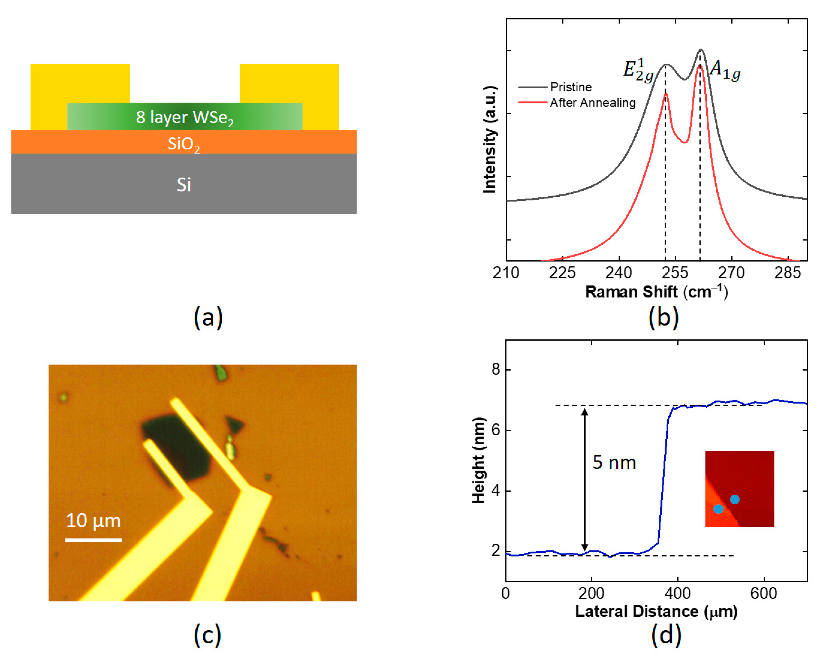
Figure 1. (a) Schematic of the WSe2 device. (b) Raman spectrum of the WSe2 before and after annealing. (c) Optical microscope image of the device. (d) AFM image and height profile of the WSe2 layer.
Applsci 12 08119 g001
Figure 2. (a) Transfer characteristics curve of the WSe2 device measured at 300 K after annealing at different temperatures on a linear scale (legend shows the annealing temperature in Kelvin, and inset represents the IdVd curve of the device). (b) Transfer characteristics curve of the WSe2 device measured at 300 K after annealing at different temperatures on a semi-logarithmic scale (legend shows the annealing temperature in Kelvin). (c) The ratio of on current to the off current of the device as a function of annealing temperatures. (d) Schematic band diagram showing Ti and WSe2 before and after contact.
Applsci 12 08119 g002
Figure 3. (a) The field-effect mobility of the WSe2 device as a function of annealing temperature. (b) The hysteresis of the device as a function of annealing temperature. (c) The off current of the device as a function of annealing temperature. (d) Surface roughness of WSe2 as measured by AFM before and after annealing.
Applsci 12 08119 g003
Publisher’s Note: MDPI stays neutral with regard to jurisdictional claims in published maps and institutional affiliations.