Article

Flow Performance and Its Effect on Shape Formation in PDMS Assisted Thermal Reflow Process

1
School of Mathematics & Physics, Anhui Jianzhu University, Hefei 230601, China
2
Department of Precision Machinery and Precision Instrumentation, University of Science and Technology of China, Hefei 230026, China
*
Author to whom correspondence should be addressed.
Appl. Sci. 2022, 12(16), 8282; https://doi.org/10.3390/app12168282
Submission received: 13 July 2022 / Revised: 13 August 2022 / Accepted: 18 August 2022 / Published: 19 August 2022
(This article belongs to the Section Optics and Lasers)

Abstract

:
A theoretical model is proposed to investigate the mechanism of shape formation in polydimethylsiloxane (PDMS) assisted thermal reflow. The thermal curing of PDMS is characterized by a dual-Arrhenius equation and its effect on the reflow process is discussed. It shows that due to the thermal curing of PDMS, the dynamic wetting and interface evolution are constrained successively. This is quite different from the traditional thermal reflow, and will result in unique flow performance, which will facilitate the abilities of the base constraint and shape retaining for the thermal reflow process. These advantages are critical to obtain well-defined microstructures in a simple and controllable way. Theoretical simulations of shape formation are in good agreement with the experimental results. These results provide a comprehensive understanding on PDMS assisted thermal reflow and offer a theoretical guideline for a facile yet versatile fabrication method for high quality microstructures.

1. Introduction

Thermal reflow is an economical and efficient post-processing method [1,2], which is widely used following many fabrication methods [3,4] to obtain microlens with high quality surface. Usually, the microstructures tend to reflow to spherical shapes according to the principle of energy minimum. To obtain more complex and well-defined shapes, many approaches have been proposed [5,6,7]. Kim et al. [8] proposed a geometry-guided thermal reflow method to guide the reflow along the geometric boundaries of the adjacent thermoset microstructures. Hung et al. [9] used two photoresists with different melting temperatures to fabricate tilted microlens with base constrained. In our previous study [10,11,12], by introducing PDMS in a thermal reflow process, it offers a facile and effective way to obtain high quality microstructures with desired shapes. Furthermore, the cured PDMS can be used as a soft mold to transfer micro/nano structures to other materials [13,14].
To reveal how the photoresist flow will affect the microlens formation and find out the mechanism of this unique process, a suitable theoretical model is required. Thus far, many calculation models have been introduced to explore the thermal reflow process based on analytical [15,16] or numerical [17,18,19,20,21] methods. Solving hydrodynamic equations by numerical methods [17,18,19] is a common calculation model for exploring the general shape evolutions of various microstructures during thermal reflow process conducted in the air. In those models, the dynamic substrate wetting is ignored, which is disadvantageous to calculate the thermal reflow process accurately. It is precisely described in an energy-based numerical calculation model by inputting an apparent contact-angle-evolution time constant [20,21]. However, the method is not suitable for investigating the complex velocity distribution induced by thermal curing of PDMS over temperature and time.
In this study, we propose an improved theoretical model to analyze the PDMS assisted thermal reflow process and explore the shape formations of photoresist microstructures under curing PDMS. The theoretical model is based on hydrodynamic equations and a continuum surface force model. The reflow mechanism is revealed by analyzing the simulated reflow results of two typical microstructures. Based on the thermal reflow mechanism and the numerical calculation model, the thermal reflow process covered by PDMS can be investigated conveniently.

2. Materials and Methods

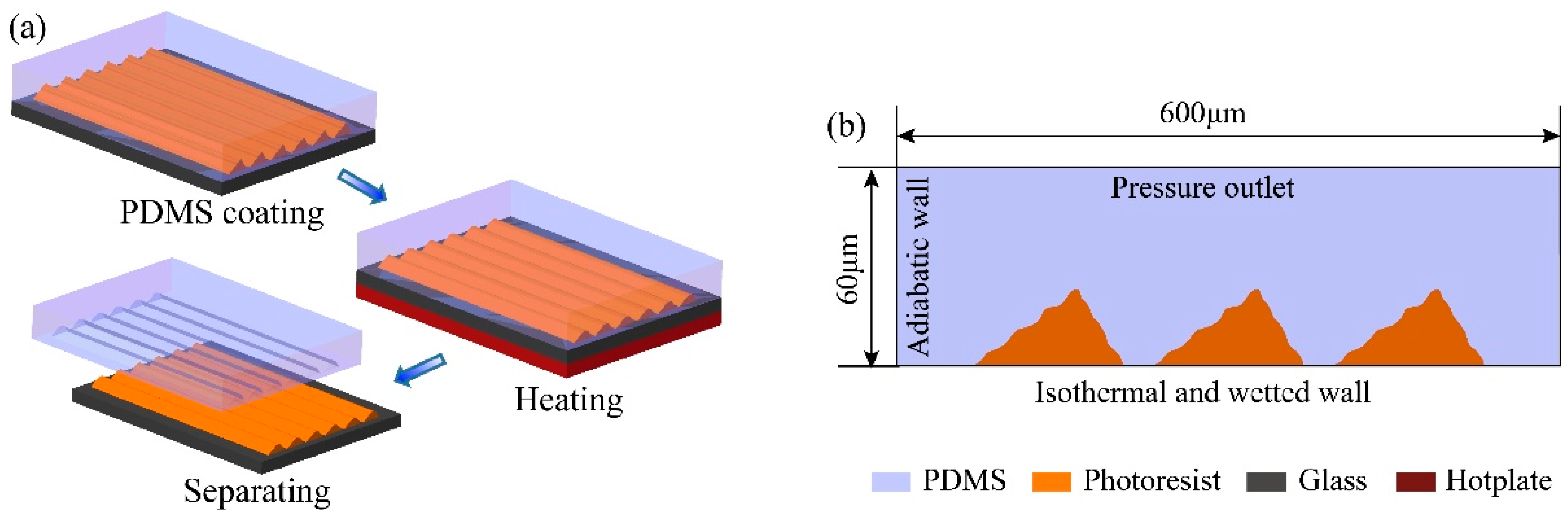
2.1. Geometry Model and Boundary Conditions

PDMS assisted thermal reflow is a novel approach to fabricate microstructures with different morphologies and layouts [10,11,12]. The process is presented in Figure 1a. Firstly, the PDMS (SYLGARD 184, Dow Corning, Midland, USA, 10:1 wt/wt in our case) solution is poured on the substrate at room temperature to cover the microstructures prepared by home-made DMD (Digital Micromirror Device)-based maskless lithography. The PDMS solution will flow to level because of low surface energy. Then, the thermal reflow process is conducted on the hotplate (Lab Tech EH35A plus) with temperature set at 180 °C for 150 s. In this process, the shapes of microstructures will be reshaped or smoothed by the surface tension. Finally, the sample is cooled down at ambient temperature and the PDMS film is separated from the formed tilted cylinder microlens array.
According to the thermal reflow process, a two-dimensional geometry model is established as shown in Figure 1b. It adopts the cross-section of a part of the practical reflow system. The top boundary is set as pressure outlet. The side boundaries are set as adiabatic wall, for each microstructure has nearly the same reflow environment, which means that there will be hardly any heat transfer between the adjacent microstructures. For the bottom boundary, an isothermal and wetted wall is imposed on it.

2.2. Material Properties

Photoresist (AZ P4620, Clariant Crop, Muttenz, Switzerland) can be regarded as a viscous fluid once the heating temperature is far higher than the glass transition temperature at 115 °C, and the cross-linking is avoided simultaneously [22]. In our experiment, the reflow temperature is set to 180 °C, and the PDMS covered on the photoresist prevents the cross-linking of photoresist due to isolation of oxygen [17,22]. Hence, the melting photoresist is considered as a viscous fluid with a viscosity of about 385 Pa∙s [18] in the simulation model. PDMS is a kind of thermal curing silicon rubber. In the thermal reflow process, the viscosity of PDMS increases over time at a given heating environment. Before reaching the gel point, it can be regarded as a viscous fluid. The specific description of PDMS viscosity during this process is very complex and will be discussed in the next section. The interfacial tension of photoresist and PDMS σrp, which represents the tensile force per unit length on the interface of PDMS and photoresist, can be determined by their surface tension [23]. It is calculated to be 28 mN/m with parameters from the references [24,25]. The other main properties involved in our simulation are shown in Table 1.

2.3. Theoretical Model

In this study, both PDMS and photoresist are assumed as incompressible Newton fluids [18,19]. Additionally, the thermal reflow process is described by Navier–Stokes and continuity equations. At the given dimension scale of microstructures, the gravitational effect can be ignored when compared with interfacial tension [18]. The momentum equation is shown as follows:
t ( ρ v ) + ( ρ v v ) = p + [ μ ( v + v T ) ] + F
Here, p, v , ρ and μ are static pressure, velocity, density and viscosity, respectively. The source term F in our case is related with interfacial tension.
The reflow process involves interaction between PDMS and photoresist. Herein, we introduce the multiphase flow system with the volume of the fluid model to calculate the interface evolution of PDMS and photoresist. In this way, only a single momentum equation is required to be solved throughout the domain to obtain the resulting velocity field shared among the phases. Therefore, the mixture velocity is given as follows:
v = α r ρ r v r + α p ρ p v p α r ρ r + α p ρ p
where the subscripts r and p represent photoresist and PDMS, respectively. Additionally, the volume fraction of photoresist αr and the volume fraction of PDMS αp satisfy αr + αp = 1. Similarly, the mixture density and mixture viscosity are decided by volume fraction and basic material properties and presented by αr ρr + αp ρp and αrμr + αp μp, respectively.
Interfacial tension is the dominated force in the reflow process. It is critical to introduce it into the momentum equation. Here, the continuum surface force model [26] is utilized to express the interfacial tension, where the interface curvature is computed from the local gradient in the interface normal at the interface. In our case, interface normal is defined as the gradient of the αp, and the curvature k is defined in terms of the divergence of the unit interface normal:
k = α p | α p | .
Then, the interfacial tension expressed as volume force Fvol, which is decided by the interfacial tension coefficient of PDMS and photoresist σrp and the curvature of the interface, has following form:
F v o l = σ r p ( α r ρ r + α p ρ p ) k p α p 1 2 ( ρ r + ρ p ) .
Previous models usually ignore dynamic wetting along substrate [16,17], while it is a significant factor for exploring mechanism of PDMS assisted thermal reflow. The dynamic boundary condition associated with the contact angle θw (about 43° in our case) is introduced in this paper. It is implemented by replacing the unit normal in Equation (3) with the normal near the wall shown in the following:
n ^ = n ^ w cos θ w + t ^ w sin θ w
where n ^ w and t ^ w are the unit vectors normal and tangential to the wall, respectively.
The tracking of the interface between PDMS and photoresist is accomplished by the solution of a continuity equation for the volume fraction of them. The continuity equation is showed in the following:
ρ t + ( ρ v ) = 0 .
For the photoresist, this equation has the following form:
1 ρ r [ t ( α r ρ r ) + ( α r ρ r v r ) ] = 0 .
For the PDMS, the continuity equation has a similar form as Equation (7). The numerical calculation of PDMS assisted thermal reflow is implemented by a commercial computational fluid dynamics software ANSYS-Fluent 16.

3. Results and Discussion

3.1. Thermal Curing Process of PDMS

PDMS thermal curing performance during PDMS assisted thermal reflow process is a key factor for shape evolution. The curing process of PDMS can be described by the dual-Arrhenius equation [27] shown as follows:
ln η ( t ) = ln η + E a , η R T ( t ) + 0 t k e E a , k R T ( t ) d t
where T, t and R are the temperature, the time and the ideal gas constant, respectively, η is the calculated viscosity at T = , k is the calculated apparent kinetic factor at T = ∞, Ea,k is the activation energy for the gelation, and Ea,η is the active energy for the viscosity. Here, η, k, Ea,k and Ea,η are unknown parameters, which can be calculated with measured data including the viscosity varying over temperature at initial time and the viscosity varying over time at given temperatures. Then, we can obtain the fitting dual-Arrhenius equation and the predicated viscosity curves for PDMS. The isothermal viscosity curves are measured by rheometer (Discovery HR-2) and shown in Figure 2a indicated by the solid lines. The corresponding predicated viscosity curves are shown in Figure 2a, indicated by the dashed lines. It should be noted that in Figure 2a, there are discrepancies between the measured and predicted viscosities curves, which may have a certain impact on the simulation results. However, with the increase of time, the deviations become much smaller, especially for those results at a comparatively high temperature of 90 °C and 110 °C. For the thermal reflow process is conducted at a relatively high temperature of 180 °C, it will have a very limited influence on the overall simulation results.
In the simulation process, the viscosity equation of PDMS is expressed in the form of user-defined function. The viscosity curves varying over time at different heights can be obtained by recording viscosity value in the simulation process, as shown in Figure 2b. The red line and the blue line are the viscosity curves at the height 0.5 μm and 12 μm above the substrate, respectively. These two heights represent the bottom and the top layer of PDMS surrounding the microstructures, respectively. It can be seen that the viscosity is relatively low in two layers before 1.2 s. Then, the viscosity increases sharply from a relatively lower viscosity to 385 Pa∙s (the viscosity of the photoresist) in less than 2 s, as shown in the inset in Figure 2b. At this stage, the viscosity gradient in height direction will become larger. Along with the process of heating, PDMS at different heights will get high viscosity and reach the gel point gradually.

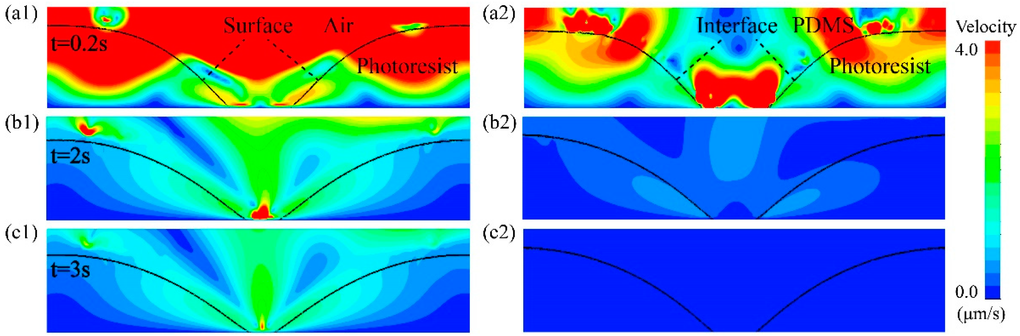
3.2. The Base Constraint Ability

The base constraint ability is essential for fabricating microstructures with accurate shapes and layouts. Herein, thermal reflow process of cylinder microlens array is simulated to explore the base constraint ability of PDMS assisted thermal reflow. Figure 3(a1–c1) and (a2–c2) show the velocity distributions at different times (0.2, 2 and 3 s) during the thermal reflow process conducted in the air and PDMS, respectively. In Figure 3(a1), most melting photoresist has a large velocity, which indicates rapid corner rounding and photoresist creeping at the beginning of the thermal reflow. Then, the velocity of the top melting photoresist decreases greatly, while the velocity of melting photoresist near the bottom surface still keeps relatively larger, as shown in Figure 3(b1,c1). It indicates that the dynamic substrate wetting drives the constant shape evolution after the initial fast shape transition. Similarly, the velocity of most melting photoresist is large at the beginning of PDMS assisted thermal reflow, as shown in Figure 3(a2). However, it is relatively smaller than that shown in Figure 3(a1) due to the introduction of PDMS. Figure 3(b2) shows the velocity distribution at the moment when there is a large viscosity gradient in the height direction. It can be clearly observed that the dynamic wetting of bottom melting photoresist is constrained, while the top melting photoresist keeps on creeping with low velocity. Figure 3(c2) shows the velocity distribution when all the surrounding PDMS is almost cured. The flow of all the melting photoresist, especially the bottom melting photoresist, is further restricted. During the whole PDMS assisted thermal reflow process, the dynamic wetting along the substrate is constantly constrained.
Figure 4a,b are shape evolutions of cylinder microlens during the thermal reflow conducted in the air and PDMS, respectively. Comparing the shape evolution near the substrate, which is indicated by the dashed box shown in Figure 4a,b, it can be observed that the dynamic wetting along the substrate is constrained in Figure 4b. A typical cylinder microlens array with a little gap is simulated, and the comparison between the simulated and experimental profiles is shown in Figure 4c. It shows that the simulated profile and the experimental profile have a good agreement. The adjacent microlens do not merge together, which indicates that the base is constrained very well. Figure 4d shows the volume fraction contour and SEM image of the cross-section of the cylinder microlens, respectively. The simulated formed shape is in good agreement with the experimental results.

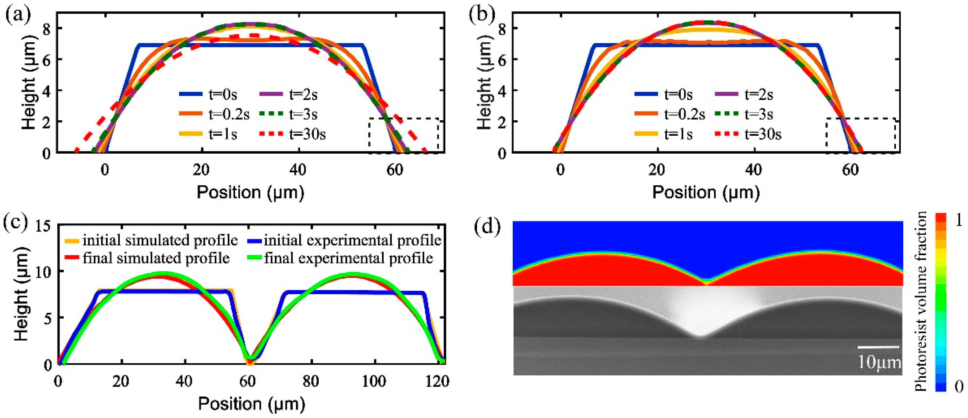
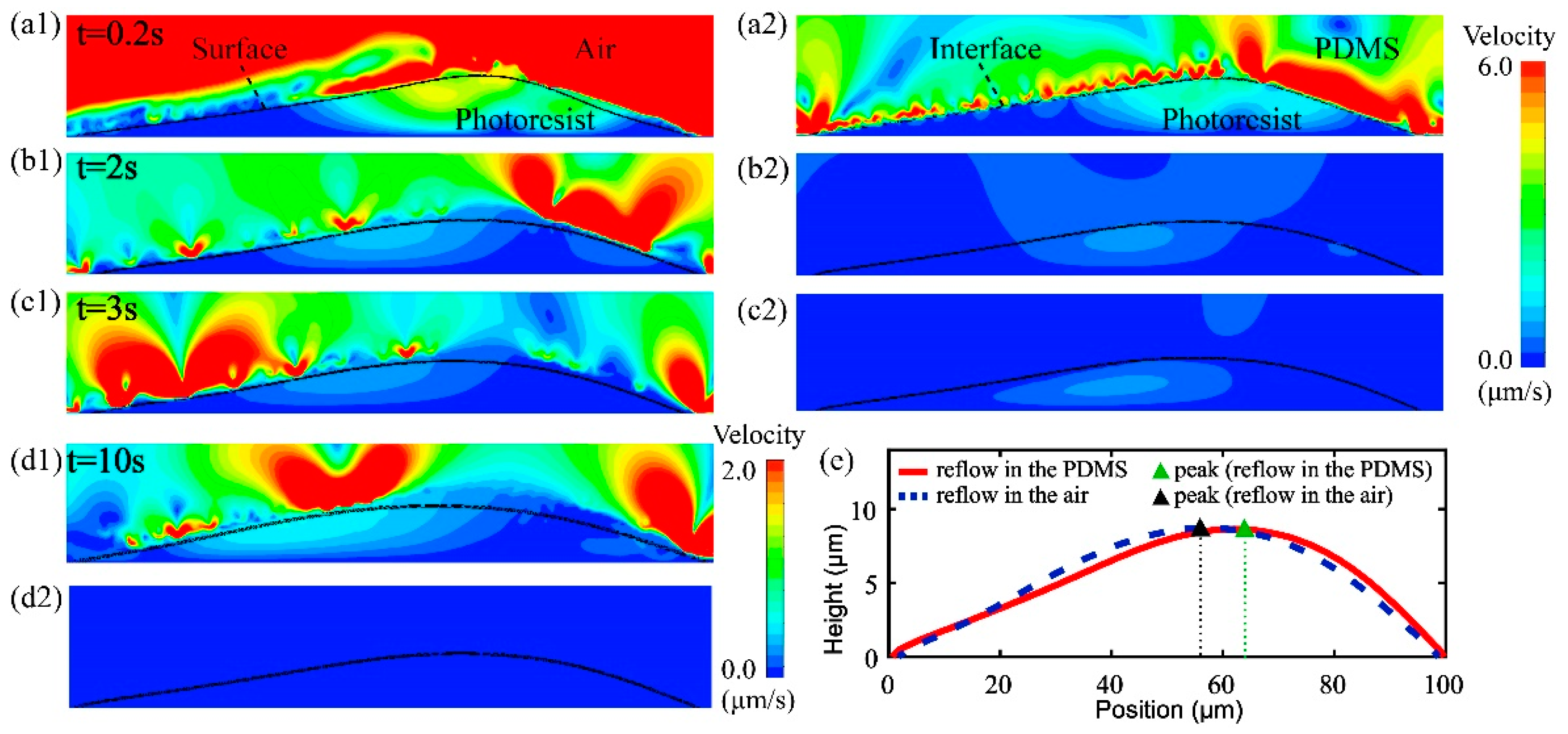
3.3. The Shape Retaining Ability

The shape retaining ability is an important factor in fabricating microstructures with variable desired shapes. Here, it is demonstrated in the PDMS assisted thermal reflow process of a typical tilted cylinder microlens. Figure 5(a1–d1) and (a2–d2) show the velocity distributions at different moments (0.2, 2, 3 and 10 s) during thermal reflow process conducted in the air and PDMS, respectively. In both two thermal reflow processes, it can be seen that the velocity of the melting photoresist is getting smaller and smaller, which indicates the shape evolution becomes slower and slower over time. Comparing Figure 5(a1–c1) with Figure 5(a2–c2), it can be found that the reflow velocity of melting photoresist under the PDMS is obviously slower than that of melting photoresist under the air. This indicates that the introduction of PDMS will lead to a smaller shape evolution velocity. Figure 5(d1,d2) show the velocity of melting photoresist at t = 10 s for the two situations, respectively. It shows that the reflow velocity is nearly 0 μm/s under the curing PDMS. This indicates that the gradually curing of PDMS will further prevent the flow of melting photoresist. To investigate the shape evolutions in these two situations, we compare the microstructure profiles obtained from Figure 5(d1,d2), as shown in Figure 5e. It can be seen that the peak of the profile curve obtained in the air is much closer to the base center than that obtained in the PDMS. This means that introduction of PDMS will decrease the shape evolution in thermal reflow process and therefore is beneficial for keeping the asymmetry of the tilted cylinder microlens.
Figure 6a shows the initial and the final profiles of the tilted cylinder microlens obtained from the simulated and experimental results. Comparing the initial and the final simulated profile, it can be seen that the final simulated profile is smoother and almost coincides with the initial simulated profile. The asymmetry of the tilted cylinder microlens can be kept well. Comparing the final simulated and experimental profile, it can be seen that the general shapes are in good agreement, except for a little profile deviation due to the shrink of the photoresist. The volume fraction contour and SEM image of the cross-section of the tilted cylinder microlens also have a good qualitative agreement, as shown in Figure 6b,c.
To further demonstrate the shape retaining ability and improvement by applying our theoretical model, we also fabricate a compound eye microlens array. Figure 7 shows the experimental results of compound eye microlens array fabricated by applying our method and conventional method. It can be seen that by applying our method a compound eye structure is well formed completely, while with the conventional method there occur an obvious fusion phenomenon between the base and the small lens. Comparing Figure 7a,b, it can be seen that our method can effectively prevent the fusion of the microlens and the base structure and ensure the formation of the compound eye microlens.

4. Conclusions

We have introduced a comprehensive approach for investigating the formation mechanism of the PDMS assisted thermal reflow process. A theoretical simulation model considering the thermal curing of PDMS is constructed. Simulation results show that the bottom shape and the interface evolution of the microstructure are constrained gradually with the thermal curing of PDMS during the reflow process. This will offer our method the abilities of base constraint and shape retaining, and allows for a steady and controllable shape formation during the process. Based on the formation mechanism, we can optimize the PDMS assisted thermal reflow process for various desirable microstructures.

Author Contributions

Conceptualization, M.L. and S.G.; methodology, S.G.; software, C.S.; validation, C.S. and S.G.; writing—original draft preparation, S.G. and C.S.; writing—review and editing, M.L.; supervision, M.L.; funding acquisition, M.L. and S.G. All authors have read and agreed to the published version of the manuscript.

Funding

Please add: This research was funded by the Scientific Research Foundation of Education Department of Anhui Province of China, grant number KJ2020JD16, the National Natural Science Foundation of China, grant number 51475442.

Institutional Review Board Statement

Not applicable.

Informed Consent Statement

Not applicable.

Data Availability Statement

Data is contained within the article.

Acknowledgments

The authors gratefully acknowledge the University of Science and Technology of China Center for Micro and Nanoscale Research and Fabrication.

Conflicts of Interest

The authors declare no conflict of interest.

References

  1. Heo, S.G.; Jang, D.; Koo, H.-J.; Yoon, H. Large-area fabrication of microlens arrays by using self-pinning effects during the thermal reflow process. Opt. Express 2019, 27, 3439–3447. [Google Scholar] [CrossRef]
  2. Dai, C.H.; Agarwal, K.; Choo, J.H. Ion-induced localized nanoscale polymer reflow for three-dimensional self-assembly. ACS Nano 2018, 12, 10251–10261. [Google Scholar] [CrossRef]
  3. Li, Y.L.; Li, K.S.; Gong, F. Fabrication and optical characterization of polymeric aspherical microlens array using hot embossing technology. Appl. Sci. 2021, 11, 882. [Google Scholar] [CrossRef]
  4. Xie, S.P.; Wan, X.J.; Wei, X.X. Fabrication of multiscale-structure wafer-level microlens array mold. Appl. Sci. 2019, 9, 487. [Google Scholar] [CrossRef]
  5. Jung, H.; Jeong, K.-H. Monolithic polymer microlens arrays with high numerical aperture and high packing density. ACS Appl. Mater. Interfaces 2015, 7, 2160–2165. [Google Scholar] [CrossRef]
  6. Bae, S.-I.; Kim, K.; Yang, S.; Jang, K.-W.; Jeong, K.-H. Multifocal microlens arrays using multilayer photolithography. Opt. Express 2020, 28, 9082–9088. [Google Scholar] [CrossRef]
  7. Lotz, M.; Needham, J.; Jakobsen, M.H.; Taboryski, R. Nanoimprinting reflow modified moth-eye structures in chalcogenide glass for enhanced broadband antireflection in the mid-infrared. Opt. Lett. 2019, 44, 4383–4386. [Google Scholar] [CrossRef]
  8. Kim, J.J.; Yang, S.P.; Keum, D.; Jeong, K.H. Asymmetric optical microstructures driven by geometry-guided resist reflow. Opt. Express 2014, 22, 22089–22094. [Google Scholar] [CrossRef]
  9. Hung, S.Y.; Chang, T.Y.; Shen, M.H.; Yang, H. Tilted microlens fabrication method using two photoresists with different melting temperatures. J. Micromech. Microeng. 2014, 24, 025013. [Google Scholar] [CrossRef]
  10. Qiu, J.; Li, M.; Ye, H.; Yang, C.; Shi, C. Fabrication of high fill factor cylindrical microlens array with isolated thermal reflow. Appl. Optics 2018, 57, 7296–7302. [Google Scholar] [CrossRef]
  11. Qiu, J.; Li, M.; Ye, H.; Zhu, J.; Ji, C. Fabrication of high fill-factor microlens array using spatially constrained thermal reflow. Sens. Actuator A-Phys. 2018, 279, 17–26. [Google Scholar] [CrossRef]
  12. Qiu, J.; Li, M.; Zhu, J.; Ji, C. Fabrication of microlens array with well-defined shape by spatially constrained thermal reflow. J. Micromech. Microeng. 2018, 28, 085015. [Google Scholar] [CrossRef]
  13. Jurgensen, N.; Fritz, B.; Mertens, A.; Tisserant, J.-N.; Kolle, M.; Gomard, G.; Hernandez-Sosa, G. A Single-Step Hot Embossing Process for Integration of Microlens Arrays in Biodegradable Substrates for Improved Light Extraction of Light-Emitting Devices. Adv. Mater. Technol. 2020, 6, 1900933. [Google Scholar] [CrossRef]
  14. Zhu, X.Y.; Xu, Q.; Hu, Y.J.; Li, H.K.; Wang, F.; Peng, Z.L.; Lan, H.B. Flexible biconvex microlens array fabrication using combined inkjet-printing and imprint-lithography method. Opt. Laser Technol. 2019, 115, 118–124. [Google Scholar] [CrossRef]
  15. Leveder, T.; Landis, S.; Davoust, L. Reflow dynamics of thin patterned viscous films. Appl. Phys. Lett. 2008, 92, 013107. [Google Scholar] [CrossRef]
  16. Hu, J.J.; Feng, N.N.; Carlie, N.; Petit, L.; Agarwal, A.; Richardson, K.; Kimerling, L. Optical loss reduction in high-index-contrast chalcogenide glass waveguides via thermal reflow. Opt. Express 2010, 18, 1469–1478. [Google Scholar] [CrossRef]
  17. Emadi, A.; Wu, H.; Grabarnik, S.; de Graaf, G.; Wolffenbuttel, R.F. Vertically tapered layers for optical applications fabricated using resist reflow. J. Micromech. Microeng. 2009, 19, 074014. [Google Scholar] [CrossRef]
  18. Zhang, H.; Li, L.; McCray, D.L.; Yao, D.G.; Yi, A.Y. A microlens array on curved substrates by 3D micro projection and reflow process. Sens. Actuator A-Phys. 2012, 179, 242–250. [Google Scholar] [CrossRef]
  19. Audran, S.; Mortini, B.; Faure, B.; Schlatter, G. Dynamical formation of microlenses by the reflow method: Numerical simulation and experimental study of the process fabrication. J. Micromech. Microeng. 2010, 20, 095008. [Google Scholar] [CrossRef]
  20. Kirchner, R.; Schift, H. Mobility based 3D simulation of selective, viscoelastic polymer reflow using Surface Evolver. J. Vac. Sci. Technol. B 2014, 32, 06F701. [Google Scholar] [CrossRef]
  21. Kirchner, R.; Schleunitz, A.; Schift, H. Energy-based thermal reflow simulation for 3D polymer shape prediction using Surface Evolver. J. Micromech. Microeng. 2014, 24, 055010. [Google Scholar] [CrossRef]
  22. Kirchner, R.; Schift, H. Thermal reflow of polymers for innovative and smart 3D structures: A review. Mater. Sci. Semicond. Process 2019, 92, 58–72. [Google Scholar] [CrossRef]
  23. Wu, S. Calculation of interfacial tension in polymer systems. J. Polym. Sci. Pt. C-Polym. Sym. 1971, 34, 19–30. [Google Scholar] [CrossRef]
  24. Bauer, J.; Drescher, G.; Illig, M. Surface tension, adhesion and wetting of materials for photolithographic process. J. Vac. Sci. Technol. B 1996, 14, 2485–2492. [Google Scholar] [CrossRef]
  25. Ismail, A.E.; Grest, G.S.; Heine, D.R.; Stevens, M.J.; Tsige, M. Interfacial structure and dynamics of siloxane systems: PDMS-vapor and PDMS-water. Macromolecules 2009, 42, 3186–3194. [Google Scholar] [CrossRef]
  26. Brackbill, J.U.; Kothe, D.B.; Zemach, C. A continuum method for modeling surface-tension. J. Comput. Phys. 1992, 100, 335–354. [Google Scholar] [CrossRef]
  27. Stieghorst, J.; Doll, T. Rheological behavior of PDMS silicone rubber for 3D printing of medical implants. Addit. Manuf. 2018, 24, 217–223. [Google Scholar] [CrossRef]
Figure 1. (a) The process of PDMS assisted thermal reflow. (b) Geometry model and boundary conditions.
Applsci 12 08282 g001
Figure 2. (a) Measured and predicted viscosity curves of PDMS at different isothermal temperatures. (b) Viscosity curves varying over time at the two different heights of the simulation model.
Applsci 12 08282 g002
Figure 3. The simulated velocity distributions of cylinder microlens array during thermal reflow process: at (a1) t = 0.2 s, (b1) t = 2 s and (c1) t = 3 s conducted in the air, at (a2) t = 0.2 s, (b2) t = 2 s and (c2) t = 3 s conducted in the PDMS. The black lines in figures represent surface and interface, respectively.
Applsci 12 08282 g003
Figure 4. The shape evolutions of cylinder microlens during thermal reflow process conducted in the (a) air and (b) PDMS. (c) The initial simulated and experimental profiles, final simulated and experimental profiles of high fill-factor cylinder microlens array. (d) The volume fraction contour and SEM cross-sectional image of high fill-factor cylinder microlens array.
Applsci 12 08282 g004
Figure 5. Velocity distributions of tilted cylinder microlens during thermal reflow process: at (a1) t = 0.2 s, (b1) t = 2 s, (c1) t = 3 s and (d1) t = 10 s conducted in the air, at (a2) t = 0.2 s, (b2) t = 2 s, (c2) t = 3 s and (d2) t = 10 s conducted in the PDMS. The black lines in figures represent surface and interface, respectively. (e) The profile of tilted cylinder microlens of thermal reflow conducted in the air and PDMS at t = 10 s.
Applsci 12 08282 g005
Figure 6. (a) The initial simulated and experimental profiles, final simulated and experimental profiles of tilted cylinder microlens. The volume fraction contour (b) and SEM cross-sectional image (c) of tilted cylinder microlens.
Applsci 12 08282 g006
Figure 7. The experimental results of compound eye microlens array fabricated by applying the proposed method (a) and the conventional method (b).
Applsci 12 08282 g007
Table 1. Specific heat, thermal conductivity and density of PDMS and photoresist.
ParametersUnitPDMSPhotoresist
Specific heatJ∙kg−1∙K−115401470
Thermal conductivityW∙m−1∙K−10.180.19
Densitykg∙m−310301085
Publisher’s Note: MDPI stays neutral with regard to jurisdictional claims in published maps and institutional affiliations.

