Featured Application
This research provides theoretical support for the design and improvement of transformer winding resistance to a short circuit and has certain guiding significance for real-time monitoring of transformer winding acceleration.
Abstract
The existing research on the distribution characteristics of displacement and acceleration of the transformer axial vibration under short-circuit conditions is based on ignoring the damping parameters. An accurate description of the axial distribution characteristics of the windings, especially for the axial vibration of the winding under short-circuit conditions, has a poor effect. In this paper, the damping, stiffness, and mass parameters between windings are comprehensively considered, and the classical “mass-spring-damping” axial vibration mathematical model of transformer windings is established. After solving, the natural frequency, main mode shape, displacement, and acceleration of each wire cake of the multi-degree-of-freedom (multi-DOF) vibration system were quickly obtained. The relationship between the axial displacement and acceleration of the wire cake and the axial deformation of the transformer winding was discussed, and the transformer winding axis was summarized as well as characteristics of the vibration distribution.
1. Introduction
Power transformer plays an extremely important role in the power system and is the nerve center of the power system, which undertakes the task of voltage and current conversion. Once it breaks down, it will affect a wide range and even lead to the paralysis of a power system [1,2]. About half of all transformer damages are due to insufficient short-circuit resistance of the transformer. The accumulation of axial deformation of a transformer due to short circuits is the primary cause of transformer short circuit damage accidents [3,4]. When a transformer is short-circuited, the maximum short-circuit current on the winding is 20–30 times the rated current [5]. Due to the action of the electromagnetic force, the huge electrodynamic force bends and deforms the winding in the axial direction. When the elastic deformation of winding transfers to plastic deformation, the transformer has irreversible structural failure [6,7].
Axial deformation of transformer winding caused by a short circuit can be attributed to the axial vibration of winding [8,9]. Euler established a mechanical model of a multi-DOF vibration system with mass particles such as stiffness spring connection in the 18th century [10], which has further evolved into the “spring-mass-damper” model in subsequent studies to describe the axial dynamic characteristics of winding [11,12]. So far, this model is still the mainstream analysis model for analyzing axial stability. Based on this model, many scholars have studied the axial vibration of winding through simulation and modeling. Liang Guangcheng et al. calculated the short-circuit electrodynamic force of a transformer by using a finite element method and short-circuit electrodynamic force calculation software, and carried out static and dynamic analysis and calculation, respectively [13]; Hyun-Mo Ahn et al. used the finite element method to calculate the short-circuit electrodynamic force acting on each disk of dry-type transformer winding in case of a short circuit by using a finite element method [14]; Hu Yiwei conducted modal analysis on the vibration signal corresponding to the axial vibration of a transformer under transient operating conditions during power failure by using an operating modal analysis method, and studied and analyzed the vibration characteristics of the transient process and the influence of loose winding pressing force on axial vibration [15]. These literatures studied the mechanical stability changes of winding caused by axial force. However, the influence of the distribution of axial vibration on the transformer cannot be determined. Therefore, some scholars have also conducted research on the distribution model of the axial vibration of the transformer winding.
Xu Yongming et al. calculated the short-circuit electrodynamic force distribution of transformer winding by using a three-dimensional finite element model [16]. Based on the field-circuit coupling method, Wang Xiwen et al. used the transient field analysis method to obtain the distribution of leakage magnetic field and electromagnetic force in the winding area and obtained the distribution law of the axial deformation of the transformer in the whole process in the transient structure field [17]; D. J. Allen believed when the transformer is short circuited, the axial displacement of winding presents a “V” shape distribution, that is, the axial displacement at the middle of the winding is greater than at the end of the winding [18]. Ji Shengchang et al. believed that axial vibration acceleration of winding presented an “M” shape distribution law, that is, the acceleration amplitude at the height of 1/4 and 3/4 of the winding is greater than at the end and middle of the winding [12,19]. However, in the process of calculation and solution, the damping parameters are ignored in the above literature, and only the ideal transformer without damping is considered, which is not universal and cannot be applied to a transformer in an actual situation.
Therefore, this paper firstly deduced the theoretical formula of the transformer axial deformation and built the axial theoretical model of the transformer winding under the condition of a short circuit with damping and multiple degrees of freedom. The accuracy of the model is verified by the frequency sweep, the axial distribution characteristics of the windings during the short-circuit impact of the transformer are obtained, and the influence of the real-time parameters of the axial deformation speed and acceleration on the axial stability is discussed. It provides theoretical support for the design and improvement of transformer windings and has a certain guiding significance.
2. Axial Vibration Model of Transformer Winding
Theoretical analysis and engineering test research show that only a few parameters, such as mass and its distribution, motion damping, and restoring force characteristics, play a leading role in vibration characteristics and the response of a vibration system. The winding of a large-scale power transformer is usually a disk structure, with the alternate distribution of disks and cushion blocks in the axial direction. High-, medium-, and low-voltage windings are stacked according to the number of turns. An alternating current is connected to the winding and generates an alternating magnetic field, which forms a magnetic circuit through the iron core. The current in the winding generates alternating electrodynamic force under the action of a magnetic field and acts on each disk, and the action of alternating current makes each disk vibrate (mainly vibration in the axial direction).
2.1. Equivalent Model of Axial Vibration of the Transformer
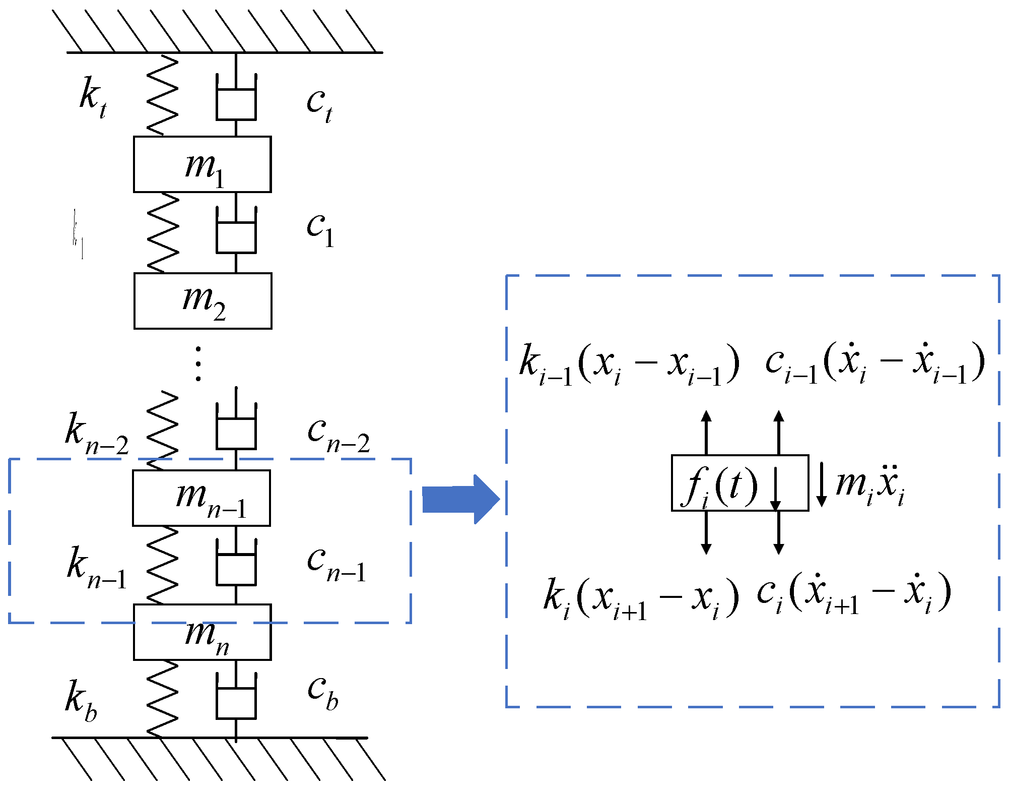
The lumped parameters of a linear vibration system are composed of mass, damping, and spring stiffness, which is usually called the mass-damping-spring model. The disk is regarded as a lumped mass; the insulating cushion block, gasket, and pressing plate between windings are regarded as elastic elements. The iron core and iron yoke are regarded as rigid bodies. The “mass-spring-damping” model is shown in Figure 1 [20].
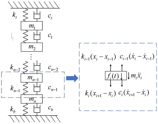
Figure 1.
Winding axial mass-damping-spring model.
As is shown in Figure 1, the mass block m in the figure corresponds to the mass of a single-layer disk, and spring stiffness ki and damping ci correspond to the equivalent stiffness and damping of an insulating paper and insulating cushion block between two layers of the disk. According to the equivalent model and stress analysis of each disk, the dynamic equations of each disk can be written as follows:
wherein, mn is the mass of the n-th layer of disk; kt and kb are the equivalent stiffness coefficients between the upper and lower pressing plates, and between the first disk and the last disk; ct and cb are the equivalent damping coefficients between the upper and lower pressing plates and between the first disk and the last disk; kn is the equivalent stiffness of the n-th disk; cn is the equivalent stiffness of the n-th disk; xn is the displacement of the n-th disk; and fn(t) is the electrodynamic force received by the n-th disk.
As shown in Table 1, the element definitions required for the solution of the axial multi-DOF vibration of the transformer winding.

Table 1.
Definition of elements in the multi-DOF model.
For convenience, Equation (1) is written in matrix form
wherein, [m] is the mass matrix of each disk, [c] is the damping matrix of each disk, [k] is the stiffness matrix of each disk, {ẍ(t)} is the vibration acceleration matrix of each disk, {ẋ(t)} is the vibration velocity matrix of each disk, {x(t)} is the vibration displacement matrix of each disk, and {f(t)} is the electrodynamic force matrix received by each disk.
When the transformer is short-circuited, only the steady-state part of the short-circuit current is considered,
wherein, is the amplitude of the AC component of the short-circuit current, and is the initial phase.
Then the electromagnetic force acting on the winding is
wherein, p is the electromagnetic force coefficient.
It can be seen that the value of the electromagnetic force frequency on the winding is twice the current frequency.
The characteristic equation of the system is as follows
wherein, ωn is the natural frequency of vibration mode in n-th order.
Substitute the r-order natural frequency successively into the eigenvalue problem equation of the system
wherein, {u} is the modal vector matrix.
Manually specify any one of the modal vectors, such as {u1(r)} = {1}, to solve all other r-order modal vectors of the system
wherein, r = 1, 2, 3, ⋯, n
Transform the physical coordinates of the system by using normal modal matrix [uN]
wherein, is the displacement matrix converted to normal modal coordinates.
Transform the vibration equation of a general multi-DOF system into a normal modal equation
wherein, is the acceleration matrix of each disk under normal modal coordinates, is the r-order damping ratio, and {N(t)} is the electrodynamic force matrix received by each disk under normal modal coordinates.
Therefore, the solution of Equation (9) can be regarded as the solution of n second-order partial differential equations with different coefficients but the same variables,
wherein, is the amplitude of electrodynamic force received by each disk, is the phase angle of electrodynamic force received by each disk, and Ω is the frequency of the electric power received by each wire cake.
The displacement equation, velocity equation, and acceleration equation can be obtained by transforming it from a modal space coordinate system to a physical coordinate system.
2.2. Parameter Matrix Acquisition
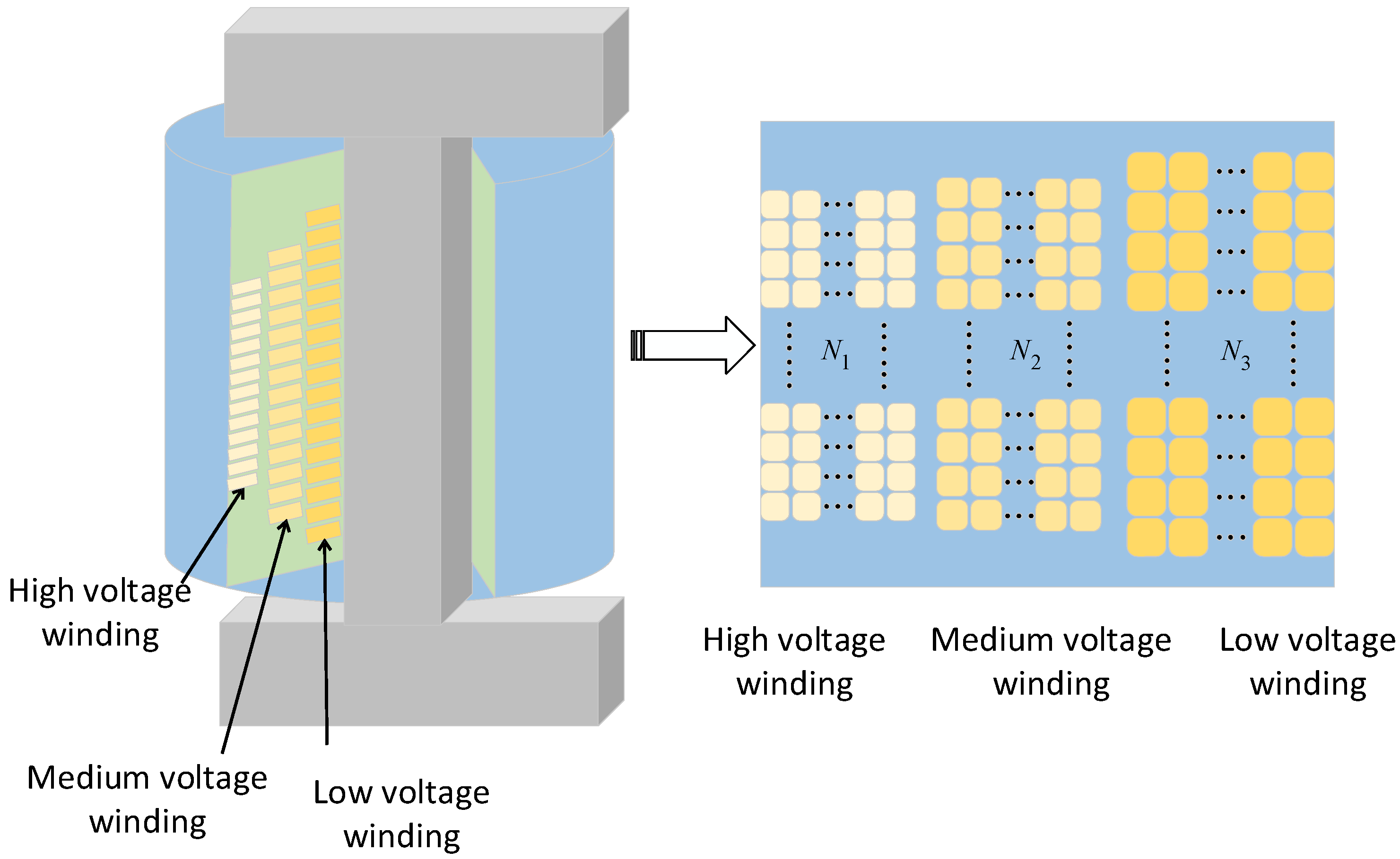
The axial section model of a three-phase transformer is shown in Figure 2. Generally, the disk-like structure is adopted in large and super large transformers with a high voltage of 110 kV and above, that is, the windings are in the radial direction, and the wire turns are continuously wound into a disk shape, and several disks are stacked into windings. The model parameter settings are completely based on the actual parameters of the real transformer.
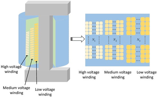
Figure 2.
Transformer axial section model.
In the axial direction, the upper and lower pressure plates are fixed at the ends of the windings, and the spacers are stacked between the turns of the coil. The support stiffness mainly depends on the spacers, which can be expressed as the following formula:
wherein, E is the elastic modulus of the cushion block, which is 50 MPa here; a is the width of the cushion block; b is the height of the conductor in the radial direction; and h is the distance between the iron core and the inner diameter of the coil.
To analyze the overall vibration, each disk is regarded as a coil as a whole. The calculation formula of disk quality is as follows:
where m is the mass of the disk, L is the total length of a single-phase conductor, n is the number of turns of a single disk, S is the cross-sectional area of the conductor, ρ is the density of the conductor, and N is the number of turns of winding. Thus, the mass of each winding disk is obtained.
According to Rayleigh damping (proportional damping), the damping matrix
where α and β are constants.
The damping ratio can be obtained
where ωnr is the r-th order natural frequency.
3. Model Calculation Based on Actual Parameters of True Transformer
Combined with the theoretical formula in the second section and the winding parameters of a power transformer, the simulation calculation of high-voltage winding under a short circuit is carried out through MATLAB (R2016a, MathWorks, Natick, MA, USA).
3.1. Model-Specific Parameters
The specific parameters of transformer winding of a 31.5 MVA/110 kV three-phase three winding power transformer used in MATLAB simulation in this paper are shown in Table 2.
Table 2.
Transformer parameters.
3.2. Natural Frequencies and Mode Shapes
By solving the characteristic Equation (5), it can be concluded that the eigenvalue and eigenvector correspond to the natural frequency and vibration mode vector of the axial winding vibration model, respectively.
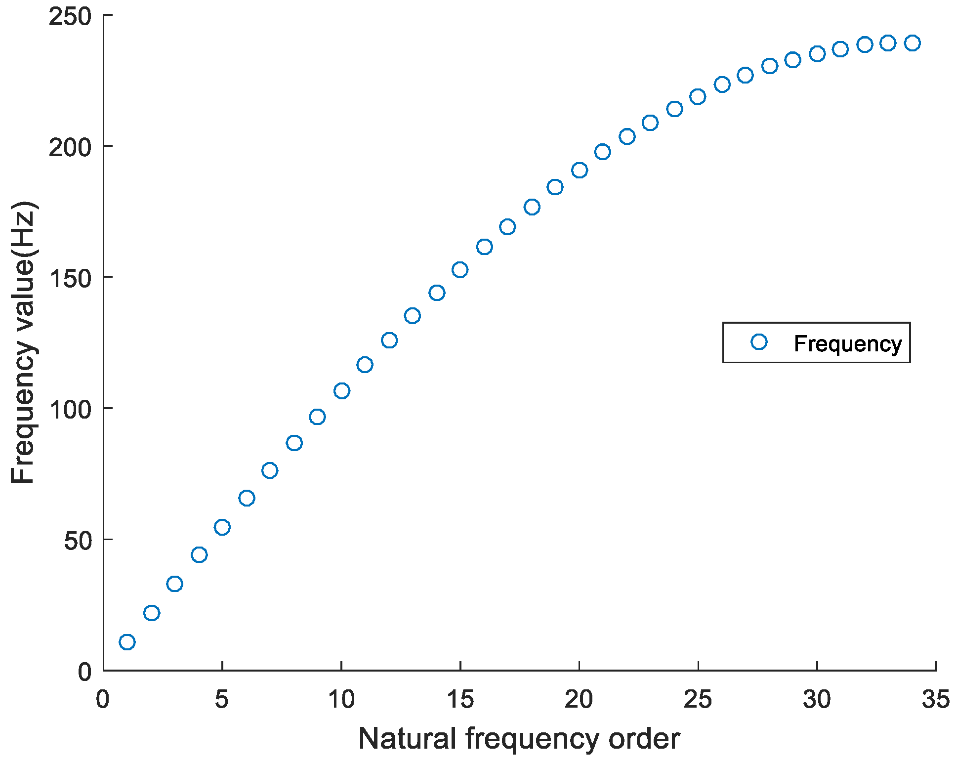
Figure 3 shows the natural frequencies of each order of high-voltage winding, which are arranged in ascending order. As shown, the frequency values, which are equal to , change linearly and change with the change of the square root of the ratio of stiffness to mass.
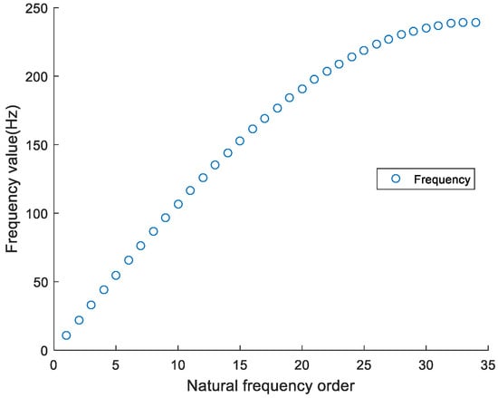
Figure 3.
Natural frequencies of each order.
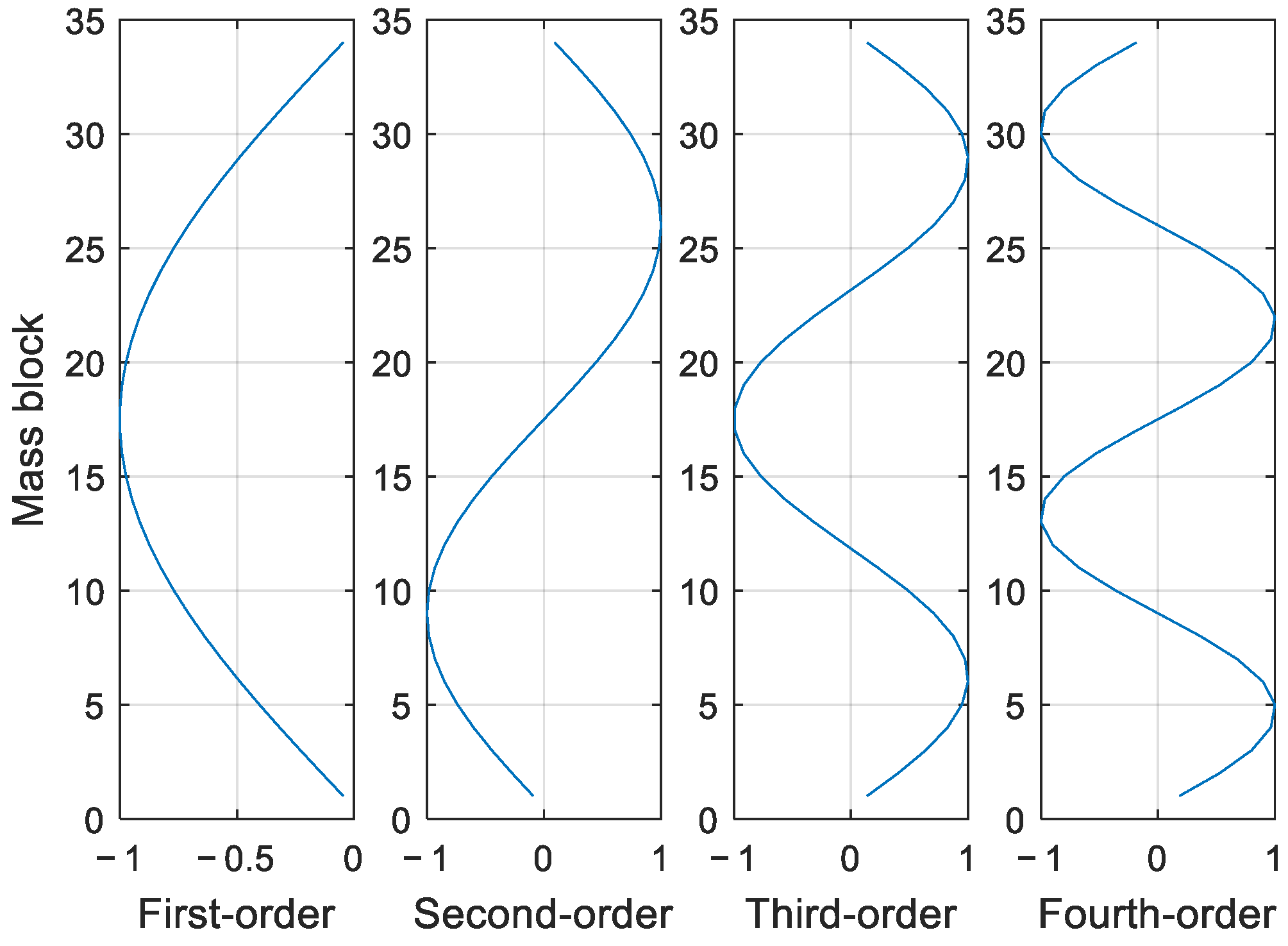
Figure 4 shows the typical modal shape diagram of the axial vibration of a winding with 34 disks by solving the system characteristic Equation (5), where the number of modal vectors is equal to the number of disks. It can be concluded from the figure that the lower the natural frequency, the greater the oscillation period of the disk, that is, the greater the impact on the system. Therefore, only the first four order modal vectors having the greatest impact on the system are taken in Figure 3. The first-order vibration mode shows the windings vibrate in the same direction in the radial direction and is distributed in a “V” shape; the second-order vibration mode shows the windings can be divided into halves from the middle part of the windings in the radial direction, and the upper half and lower half vibrate in the opposite direction, with an “N” distribution; the third-order and fourth-order modes show the higher the number of waves, the higher the distribution of waves in the fourth-order mode.
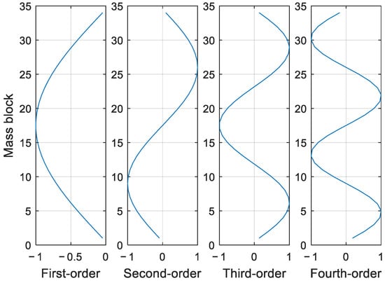
Figure 4.
The first four modes.
3.3. Displacement and Acceleration Variation Law of Disks at Different Frequencies
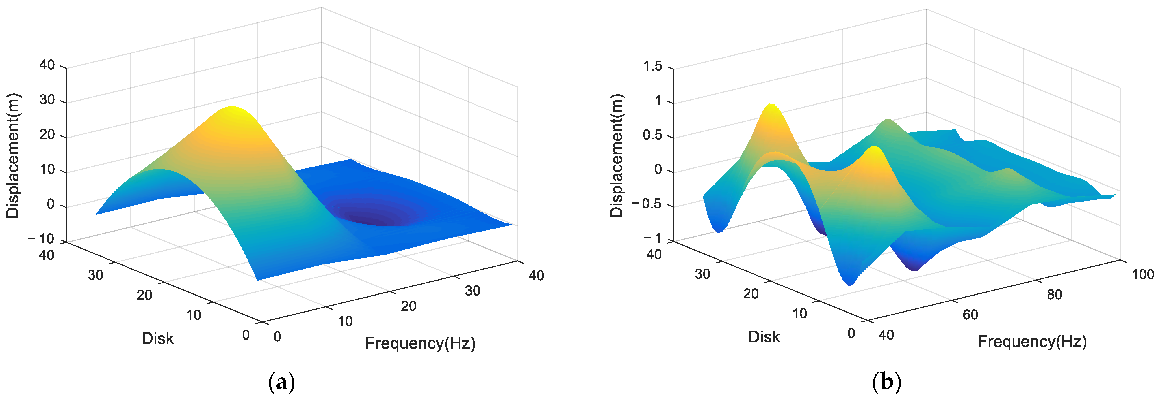
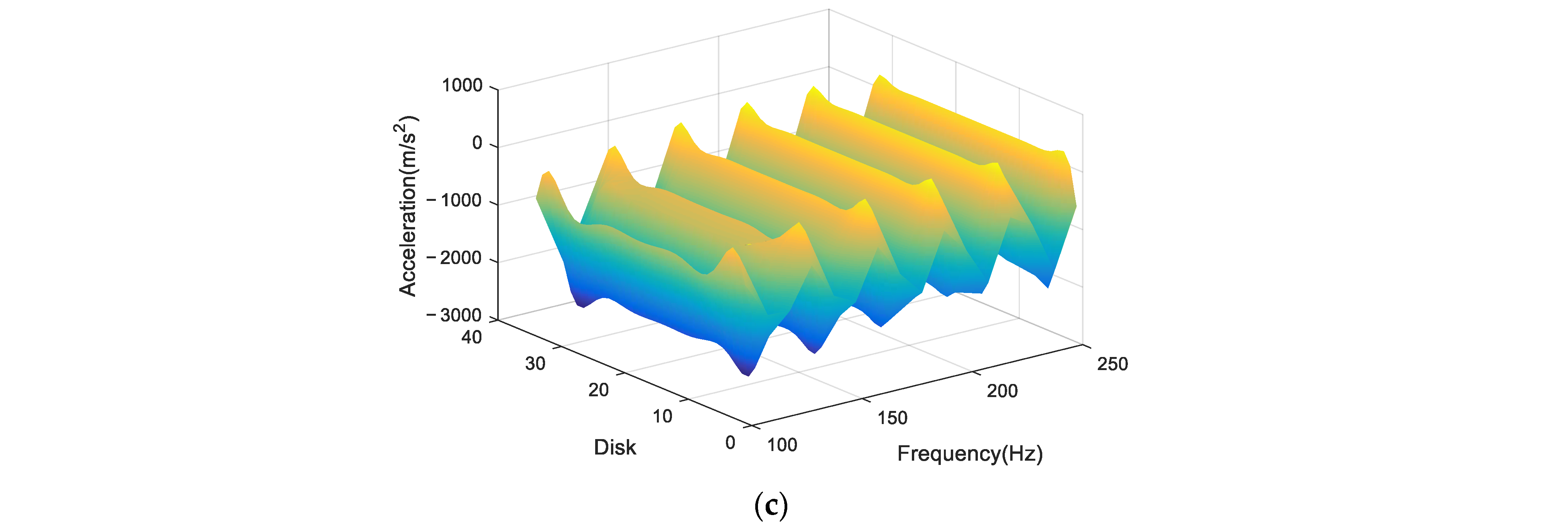
Figure 5 shows winding displacement changes in steady-state condition (t = 0.15 s) at 0–250 Hz. In the low-frequency region, the displacement is large and the amplitude is very high, distributed in an ‘arch’ shape, while in the high-frequency region, the displacement amplitude is small, but fluctuation is increasing. The theory in the previous section proves the zero nodes of high-order vibration mode increase, but the amplitude change decreases; obviously, the displacement change in Figure 5 conforms to the above theory. To better observe the displacement distribution at different frequencies, take the displacement change at 0–40 Hz as a separate observation. As shown in Figure 5a, at 0–20 Hz, the displacement is distributed in a ‘U’ shape on the winding, which is the same as the first vibration mode. With an increase of frequency from 20 Hz to 40 Hz, the displacement shape gradually turns into multiple “arches” from the ‘U’ shape, but the displacement peak decreases gradually. As shown in Figure 5b, in the winding displacement distribution at 40–100 Hz, the displacement fluctuation amplitude decreases consistently, the maximum displacement amplitude gradually approaches the head and end of the winding, fluctuation in the middle part tends to be gentle, and fluctuation in the middle part is almost zero with an increase of frequency. The winding displacement distribution gradually changes from “M” shape distribution to “three-arch” and “four-arch” shapes, which is also consistent with the distribution of vibration modes from third-order vibration modes to high-order vibration modes. As shown in Figure 5c, as frequency increases from 100 Hz to 250 Hz, displacement amplitude continues to decrease in a terraced manner, gradually close to zero, and displacement fluctuation also slowly decreases to zero.

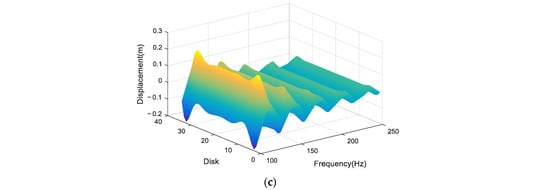
Figure 5.
Displacement of each disk at 0–250 Hz. (a) Displacement of each disk at 0–40 Hz; (b) 40–100 Hz; and (c) 100–250 Hz.
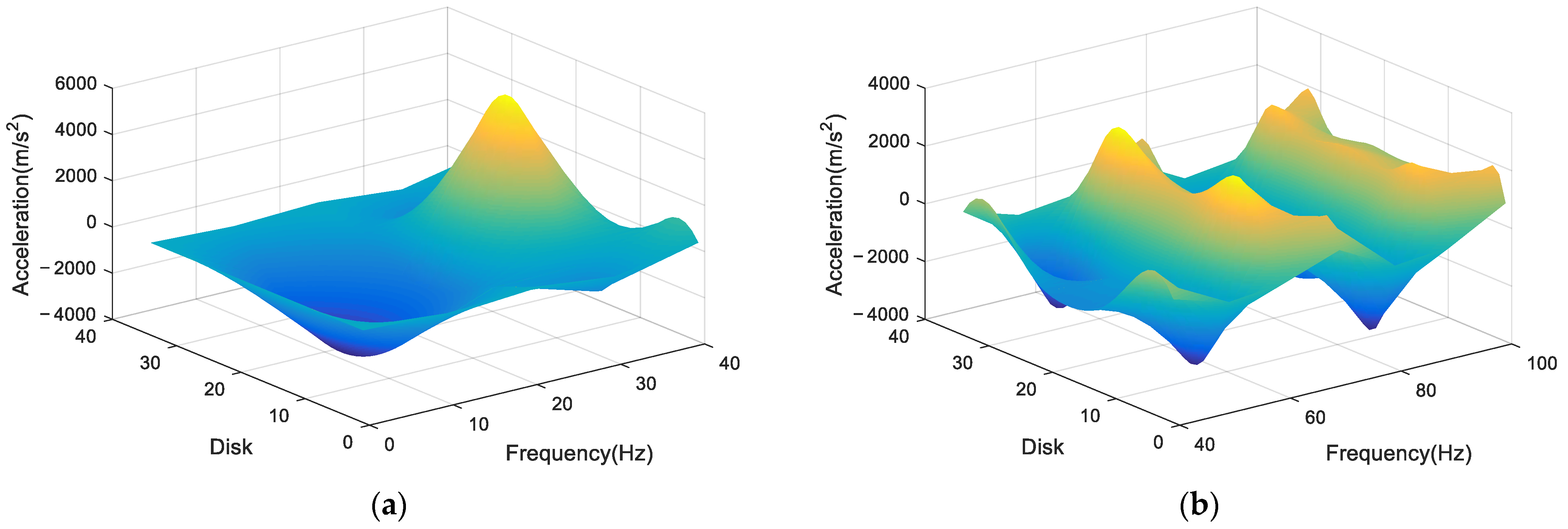
Figure 6 shows the winding acceleration changes at 0–250 Hz. In the low-frequency region, the acceleration is large and the amplitude is high, distributed by the above vibration mode law, while in the high-frequency region, the acceleration amplitude changes little and gently.

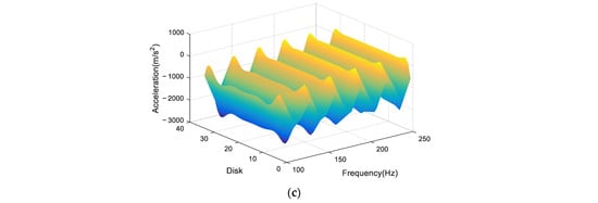
Figure 6.
Acceleration of each disk at 0–250 Hz. (a) Acceleration of Each disk at 0–40 Hz; (b) 40–100 Hz; and (c) 100–250 Hz.
Moreover, all disks have the same acceleration distribution as above. As shown in Figure 6a, at 0–20 Hz, vibration acceleration is distributed in a ‘U’ shape on the winding, consistent with the distribution law of the first vibration mode on the winding. As the frequency increases from 20 Hz to 40 Hz, the displacement shape changes from ‘U’ to ‘double-arch’ and then to ‘M’, consistent with the distribution law from the first-order vibration mode to the third-order vibration mode. Different from the displacement, the peak acceleration in each disk increases gradually with an increase in applied frequency.
As the conclusion of the above analysis, as shown in Figure 6b, the acceleration distribution of each disk is consistent with the shape change law of the vibration mode, while the amplitude does not continue to decay, but changes around a fixed value, and peak acceleration still appears near both ends of the winding.
On the contrary, as shown in Figure 6c, as the frequency increases from 100 Hz to 250 Hz, the acceleration of each disk at each resonance frequency remains at a fixed value except at both ends, and the peak value appears closer and closer to both ends of the winding.
3.4. Displacement and Acceleration Variation Law of Disks at Power Frequency
Assuming that the initial displacement and initial speed of each disk coil are zero, Period T = 2 × pi/ω, when the short-circuit current frequency is equal to the power frequency current, it can be seen from Equation (4) that the short-circuit electromotive force frequency is equal to twice the frequency of the power frequency current, that is, 100 Hz; the external short-circuit current frequency is 50 Hz, that is, at this time, the short-circuit electrodynamic frequency of the disk on the winding is 100 Hz.
In the initial stage of system vibration, transient vibration and steady vibration coexist, and the total vibration of the system is the synthetic vibration of two simple harmonic vibrations with different frequencies. In the damped system, transient vibration is quickly attenuated due to damping, and finally, only the steady vibration is retained. Therefore, the steady motion of damped forced vibration in steady vibration reflects the motion law of a damped forced vibration system. This paper focuses on the transformation and law of displacement and acceleration of the windings when they vibrate axially under short-circuit conditions, so only the steady vibration is studied with the transient vibration omitted in the simulation analysis.
Figure 7 shows the change of the displacement of the top layer of the wire cake with time during a short circuit. When the time is at 0.15, the transient amplitude of the short-circuit current tends to zero, and the steady-state vibration displacement amplitude is at the maximum moment. It can better observe the displacement change of each disk in the axial direction, so the time t = 0.15 s is taken.
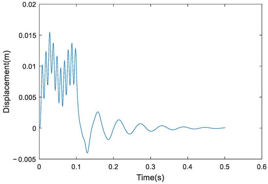
Figure 7.
Displacement response of the top disk.
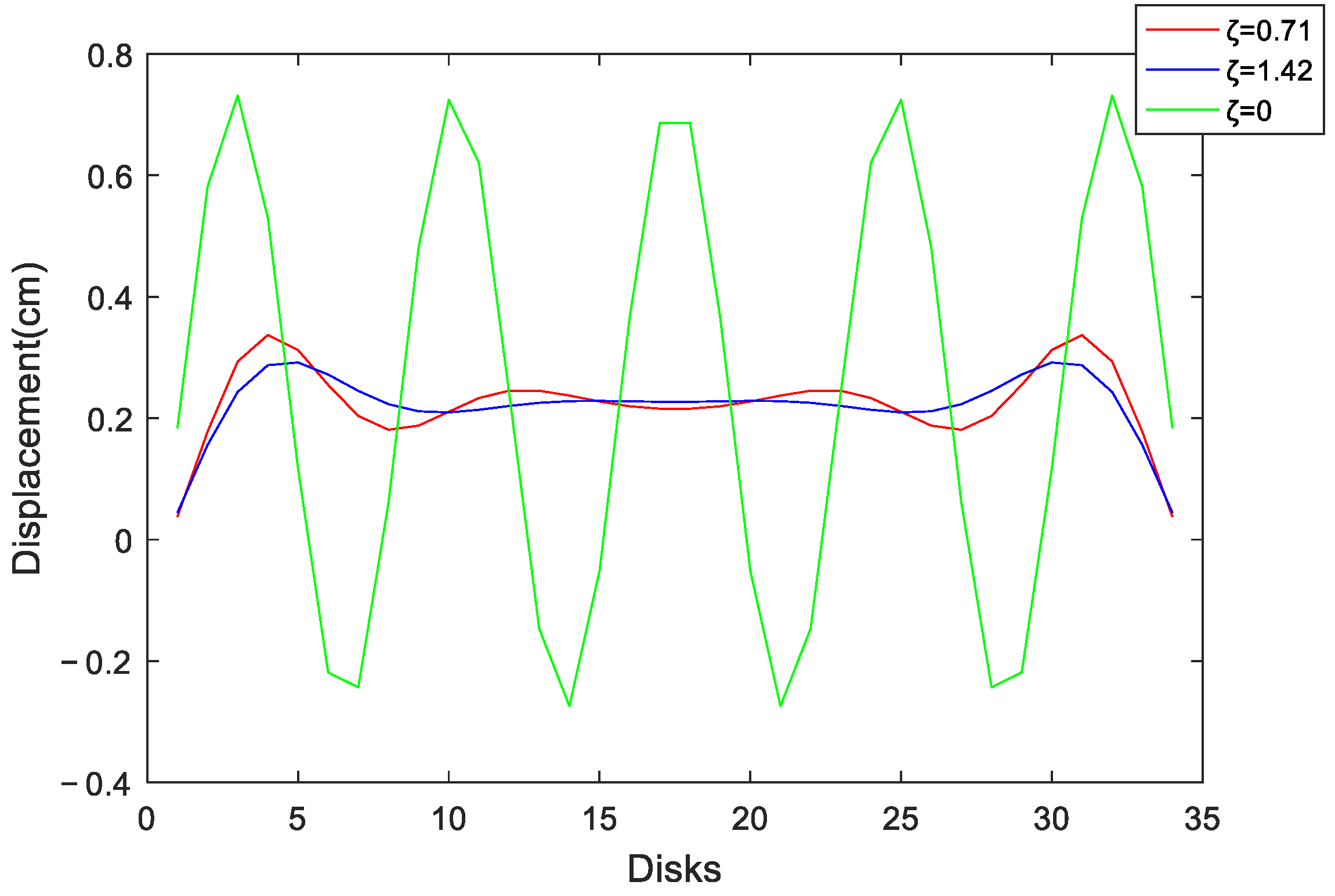
When t = 0.15 s and the damping ratio takes different values, the displacement change at this time is shown in Figure 8. The axial vibration displacement waveform of the winding is in a ‘valley’ shape, which is roughly consistent with the vibration mode law of the eighth order vibration mode, which is just around the frequency of 100 Hz, so it is believed the radial displacement distribution of the winding conforms to the theoretical calculation. The displacement amplitude reaches the peak at one-seventh of both ends, the displacements at the top and the end are close to zero, and the middle disk displacement is distributed in an “M” shape. Therefore, the deformation near both ends of the winding is large, and small in the middle part. As the damping ratio increases, the displacement oscillation amplitude of each disk gradually decreases.
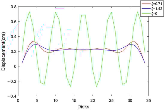
Figure 8.
Displacement of each disk under different damping ratios.
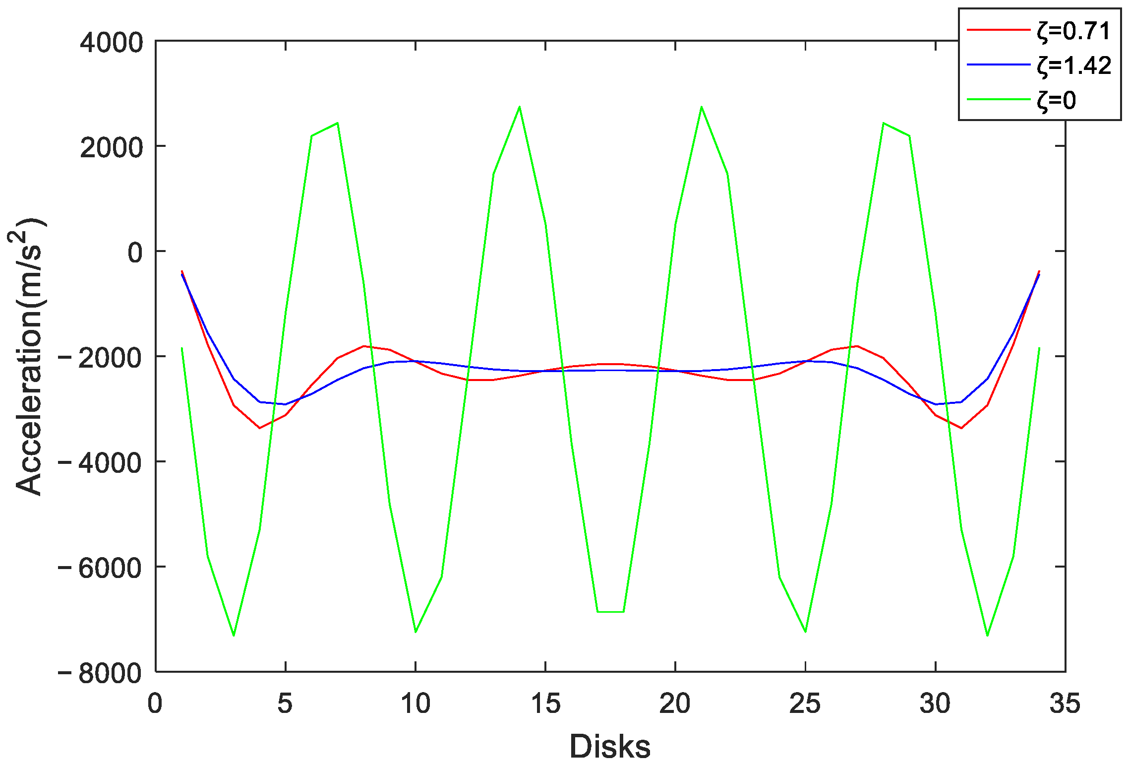
When t = 0.15 s, the acceleration change of each winding disk at this time is shown in Figure 9. Similar to the displacement waveform of each winding disk, the radial vibration acceleration waveform of the winding is in the shape of a ‘valley’, which is also roughly consistent with the vibration mode law of the eighth order mode. The acceleration near both ends of the windings reaches a maximum value, about twice the acceleration of the middle part. With the increase of the damping ratio, the acceleration oscillation amplitude of each disk gradually decreases.
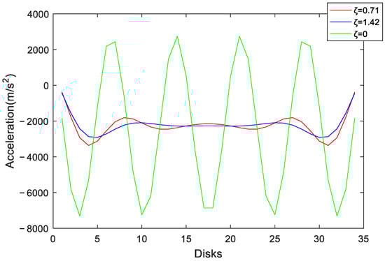
Figure 9.
Acceleration of each disk under different damping ratios.
It can be concluded that when the power transformer is in a short circuit, the winding acts as a damped multi-DOF system and the short-circuit electrodynamic force of the winding is 100 Hz. The displacement distribution law of each disk is consistent with the displacement distribution law of the eighth vibration mode. The displacement is the largest near both ends of the winding, and the middle part is relatively gentle. The displacements of the top and end disks are close to zero. The acceleration distribution law of each disk is also consistent with the eighth order vibration mode distribution law, with the peak appearing near both ends of the winding, about twice the acceleration of the middle part, while the acceleration of the disk at the top and end of the winding being relatively small. The amplitude and vibration law of winding vibration are related to the physical properties, current, and frequency of the system itself, rather than the initial conditions.
4. Results
In this paper, the distribution law of winding axial deformation in the process of transformer short circuit is studied; a multi-DOF winding “spring-mass-damping” model considering damping is established; and the variation laws of axial displacement and acceleration when the transformer with different damping ratios is short circuited at different frequencies is analyzed, which provide a new idea for the design of winding to a certain extent, further improving the short-circuit-bearing capacity of a transformer. The main conclusions are as follows:
- (1)
- In this paper, an axial vibration model of the transformer winding, considering the system damping parameters, is built. Compared with the previous V-type and M-type mode shapes, the mode shape structure calculated in this paper is more detailed and refined. At the same time, the displacement and acceleration distributions of the model at different frequencies are illustrated by sweeping the frequency.
- (2)
- Under short-circuit conditions, the acceleration and displacement of the winding are distributed in a “VMV” type, and the displacement and acceleration reach peak values at 1/8 of the upper end and 1/8 of the lower end at the same time, and the displacement and acceleration at both ends of the winding are approaching to zero; in addition, the numerical distribution of displacement and acceleration in the middle of the winding is relatively flat. With the increase of the damping ratio, the vibration amplitude shows a decaying trend.
- (3)
- According to the calculation model, suggestions for the operation and maintenance of the transformer can be put forward. The positions of the sensors for measuring the vibration acceleration can be located at the two ends, the middle, one quarter, and one-eighth of the winding. In actual operation, attention should be paid to the vibration of the upper and lower ends of the winding and the deformation of the winding. When designing the structure of the transformer winding, it is especially necessary to improve the anti-deformation and stretching ability near both ends of the winding.
In future research, we can further expand the following aspects based on the research in this paper:
- (1)
- Comparative analysis with the actual transformer short-circuit test to verify whether the theory of axial vibration of transformer windings is insufficient.
- (2)
- Further analyze the influence of different short-circuit conditions or transformer overload on the axial vibration.
- (3)
- Considering the response of transformer winding radial vibration under short-circuit conditions, comprehensive axial vibration transformer winding vibration characteristics reflect the transformer winding vibration characteristics more comprehensively.
Author Contributions
Conceptualization, S.G. and L.S.; methodology, S.G., L.S. and Y.T.; validation, L.S. and H.L.; formal analysis, S.G.; investigation, Y.T.; resources, S.G., L.S. and Y.T.; data curation, H.L.; writing—original draft preparation, S.G.; writing—review and editing, Y.T.; visualization, H.L.; supervision, L.S.; project administration, S.G. All authors have read and agreed to the published version of the manuscript.
Funding
This research was funded by Science and Technology Project of State Grid Hebei Electric Power, Fund No. Kj2019-060 and the Natural Science Foundation of Hebei Province, Fund No. E2021521004.
Institutional Review Board Statement
Not applicable.
Informed Consent Statement
Not applicable.
Data Availability Statement
Not applicable.
Conflicts of Interest
The authors declare no conflict of interest.
References
- Secic, A.; Krpan, M.; Kuzle, I. Vibro-Acoustic Methods in the Condition Assessment of Power Transformers: A Survey. IEEE Access 2019, 7, 83915–83931. [Google Scholar] [CrossRef]
- Yun, Z.; Shaoyi, L.; Xiaobo, H. Analysis of a 220kV transformer sudden short-circuit fault. Electr. Technol. 2018, 19, 94–98. [Google Scholar]
- Zhu, Y.; Ji, S.; Zhang, F.; Liu, Y.; Dong, H.; Cui, Z.; Wu, W. Vibration mechanism and influence factors in power transformers. J. Xi’an Jiaotong Univ. 2015, 49, 115–125. [Google Scholar]
- Mengyun, W. Fault statistics and analysis of transformers with 110 kV or higher voltage in 2004. Electr. Equip. 2005, 6, 35–41. [Google Scholar]
- Tenbohlen, S.; Vahidi, F.; Jagers, J.; Gebauer, J. A Worldwide Transformer Reliability Survey. In Proceedings of the VDE High Voltage Technology 2016; ETG-Symposium, Berlin, Germany, 14–16 November 2016; pp. 1–6. [Google Scholar]
- Bagheri, M.; Zollanvari, A.; Nezhivenko, S. Transformer fault condition prognosis using vibration signals over cloud environment. IEEE Access 2018, 6, 9862–9874. [Google Scholar] [CrossRef]
- Yichun, L. Calculation and Stability Analysis of Transformer Winding Short-Circuit Electrodynamic Force. Master’s Thesis, Harbin University of Science and Technology, Harbin, China, 2016. [Google Scholar]
- Xue, W.; Tao, W. Research on dynamic analysis of transformer winding deformation based on magnetic-structural direct coupling. Power Syst. Prot. Control 2017, 45, 24–30. [Google Scholar]
- Paoletti, G.J.; Herman, G. Monitoring of electrical equipment failure indicators and zero-planned outages: Past, present and future maintenance practices. In Proceedings of the Pulp and Paper Industry Conference, Charlotte, NC, USA, 23–27 June 2013; pp. 1–10. [Google Scholar]
- Wenbo, B.; Quan, B.; Haiyan, L. Vibration Mechanics Foundation and MATLAB Application; Tsinghua University Press: Beijing, China, 2015; pp. 1–2. [Google Scholar]
- Brincker, R.; Ventura, C. Introduction to Operational Modal Analysis, 1st ed.; Wiley: West Sussex, UK, 2015. [Google Scholar]
- Zhou, H.; Hong, K.; Huang, H.; Zhou, J. Transformer winding fault detection by vibration analysis methods. Appl. Acoust. 2016, 114, 136–146. [Google Scholar] [CrossRef]
- Zhenguang, L.; Chuncheng, W. Research on radial stability of transformer low-voltage windings using large-displacement geometric nonlinear theory. Transformer 2008, 39, 1–5. [Google Scholar]
- Ahn, H.M.; Oh, Y.H.; Kim, J.K.; Song, J.S.; Hahn, S.C. Experimental verification and finite element analysis of short-circuit electromagnetic force for dry-type transformer. IEEE Trans. Magn. 2012, 48, 819–822. [Google Scholar] [CrossRef]
- Yiwei, H. Research on Transformer Winding Fault Diagnosis Method Based on Spatial Vibration Distribution and Working Condition Modal Analysis. Master’s Thesis, Zhejiang University, Hangzhou, China, 2020. [Google Scholar]
- Yongming, X.; Rong, G.; Hongda, Z. Calculation of short-circuit electrodynamic force of power transformer windings. J. Electr. Mach. Control. 2014, 18, 36–42. [Google Scholar]
- Xiwen, W.; Yongteng, J.; Yongchao, Z.; Yan, L.; Dongxue, L.; Qiang, M. Calculation and Analysis of Dynamic Process of Short-Circuit Winding Deformation in Transformer. Transformers 2021, 58, 1–6+77. [Google Scholar]
- Allan, D.; Sharpley, W. The short circuit performance of trans-formers-a contribution to the alternative to direct testing. In Proceedings of the International Conference on Large High Voltage Electric Systems, Paris, France, 27 August–4 September 1980. [Google Scholar]
- Shengchang, J.; Fan, Z.; Guochao, Q.; Yeye, Z.; Hongkui, D.; Dexu, Z. Axial vibration characteristics and influencing factors of transformer windings under steady-state conditions. High Volt. Technol. 2016, 42, 3178–3187. [Google Scholar]
- Hong, K.; Huang, H.; Zhou, J. Winding condition assessment of power transformers based on vibration correlation. IEEE Trans. Power Del. 2017, 32, 1031–1038. [Google Scholar] [CrossRef]


Publisher’s Note: MDPI stays neutral with regard to jurisdictional claims in published maps and institutional affiliations. |
© 2022 by the authors. Licensee MDPI, Basel, Switzerland. This article is an open access article distributed under the terms and conditions of the Creative Commons Attribution (CC BY) license (https://creativecommons.org/licenses/by/4.0/).