Article

Towards the Feasibility of Long Range Wireless Power Transfer over an Ocean Surface

by
Louis W. Y. Liu
1,* and
Sơn Nguyễn Thành
2
1
Faculty of Engineering, Vietnamese-German University, Binh Duong New City 75000, Binh Duong, Vietnam
2
Faculty of Engineering, Eastern International University, Binh Duong New City 75000, Binh Duong, Vietnam
*
Author to whom correspondence should be addressed.
Appl. Sci. 2022, 12(17), 8751; https://doi.org/10.3390/app12178751
Submission received: 7 June 2022 / Revised: 3 August 2022 / Accepted: 24 August 2022 / Published: 31 August 2022

Abstract

:
In this work, we have realized Zenneck’s style of wireless power transfer over a seawater surface. Method: The problem can be thought of as a surface electromagnetic wave propagating along an interface between a low-loss non-polar medium and seawater. A 10 m long water-filled plastic duct was connected to two separated water tanks, with one tank identified as the transmitting end and the other the receiving end. At the transmitting end, the water tank was excited with a 100 kV plasma from a spark gap transmitter at 44 MHz. At the receiving end, surface power was harvested in an open-circuit manner with the help of a suspended monopole antenna. Results: Without any antenna, no power was received at the receiving end. However, when two monopole antennas were individually connected to the transmitter and the receiver, a power was noticeably detected and successfully delivered to multiple loads even if the water’s conductivity was low. As the salinity level increased from 0 to 5 g/L, the transmission efficiency was increased from 10% to 99%. Consistent with Marconi’s law of transmission, the transmission distance leading to the first maximum efficiency was found to be approximately proportional to square of the antenna heights. Conclusion: A vertically mounted monopole antenna enables power to be wirelessly transmitted along the interface between a low-loss dielectric medium and seawater.

1. Introduction

James Clark Maxwell was the first researcher who formulated the classical theory of electromagnetic radiation. Under his theoretical hypothesis, light is a propagating wave of electric and magnetic fields, which can travel through a vacuum without any involvement of charge movements. Similar to light, electromagnetic waves in free space were believed to be able to propagate in line of sight only.
Maxwell’s theory marked the beginning of wireless communication. Maxwell’s work remained unproven until Hertz demonstrated the existence of the Maxwell’s electromagnetic waves. The antenna in Hertz’s experiment was electrically too small to transmit a large amount of power. At that time, the idea of wireless power transfer was almost non-existent.
The research into wireless electricity did not begin until Tesla and Marconi were actively pushing for long range wireless power transfer. Tesla independently achieved a small scale of wireless power transfer. However, the actual person who practically realized long range wireless power transfer was Marconi [1,2,3,4,5,6]. Marconi unprecedentedly transmitted a series of high-voltage streamer discharges from London to New York. In his Nobel Prize acceptance speech, however, Marconi jokingly admitted he did not really understand how his invention worked. Although the history of wireless communication has finally begun, there was no explanation of the nature of the waves being sent across the Atlantic Ocean during Marconi’s prize winning experiments.
There have been many unsuccessful attempts to explain Marconi’s work. Zenneck and Sommerfeld were among the pioneers who adopted the exact solutions to Maxwell’s equations to analyze the nature of Marconi’s ground waves [7,8,9,10,11,12,13,14,15,16,17,18], but their work was fiercely debated in the scientific community. According to Zenneck and Sommerfeld’s theory, surface electromagnetic waves (or Marconi’s ground waves) propagate along an interface between two homogeneous media having different dielectric constants. Most of their explanations as well as the existing theories [19,20,21,22] have neglected a number of seemingly unrelated issues in Marconi’s work. The examples of these issues are as follows.

1.1. Use of Ground Waves

There was no suggestion that the ground waves used in Marconi’s experiments were ordinary electromagnetic waves similar to those used in Hertz’s experiments. In Hertz’s experiments, his electromagnetic waves propagated in a straight line in much the same manner as light propagating in free space. In Marconi’s experiments, the energy being sent across the Atlantic Ocean was a ground wave that was tightly bound to the surface of the Earth. The former was an unguided wave traveling at a speed of light, whilst the latter was a guided wave which operates in a similar manner as light being guided in an optical fiber.

1.2. Use of Monopole Antennas

Marconi used a long vertically mounted monopole antenna in almost all of his transmitters and receivers. According to the Marconi’s law of transmission, the maximum working telegraphic distance varied as the square of the height of the antenna if the transmitting antenna and the receiving antenna have the same height. That is, if H is the height of the antenna and D the maximum signaling distance, then we have H D . As is explained in the rest of the article, the height of an antenna top plays a critical role in determining the transmission efficiency. Wireless power transfer is practically impossible without an antenna.
In the sections that follow, our theoretical explanations will be largely based on the theory of Spoof Surface Plasmonic Polaritons [23,24,25,26]. Spoof surface plasmons, also known as spoof surface plasmon polaritons, are surface electromagnetic waves in RF/microwave frequencies that propagate along an interface between two media of sign-changing permittivities [19,20,21,22,27]. Plasma is known to be a medium of unbound and charged particles with zero net charge, whilst surface electromagnetic waves do not necessarily contain any charge. Under a high-voltage stress, these charges will move on the interface that supports the propagation of a surface electromagnetic wave, contributing an electrical current that can do work. So far, there has not been any investigation into the high voltage effects on a surface electromagnetic wave or the link between the altitude-induced atmospheric electrostatic field and the transmission efficiency. In this work, these issues are experimentally explored.
The following is a list of innovations of this work:
(1)
A high-voltage surface wave can be wirelessly transmitted along a curved or highly bent interface between a low-loss non-polar dielectric medium and a high-loss polar dielectric medium.
(2)
According to our findings, it is possible to deliver a wireless energy to multiple loads, if and only if each of the loads is connected to a vertically mounted monopole antenna which reaches a higher altitude.
(3)
Our experimental results reveal that the salinity level can enhance the transmission efficiency to a significant extent.
(4)
The correlation between the antenna height and the maximum transmission range is largely consistent with the Marconi’s law of transmission.

2. Methodology and Materials

The objective of this work was to realize wireless transmission of power to multiple loads over a seawater surface. The interface along which this energy propagates is an interface between a low-loss dielectric medium and a high-loss dielectric medium. The low-loss dielectric medium is chosen to be air or a rubber, the latter of which is a non-polar substance. The high-loss dielectric medium is chosen to be water, which is a well-known polar solvent.

2.1. Theory

The problem as stated in the objective of this work can be thought of as a surface electromagnetic wave propagating along an interface between a low-loss medium and a high-loss medium (see Figure 1). The low-loss medium is either air or a non-polar substance. The high-loss medium is a polar substance. Non-polar substances include oil or petroleum chemicals. Polar substances include water.
In this work, the high-voltage surface wave is a wave bound to a water surface, which can be water exposed to air or an interface between the rubber in the rubber tube and the water filling this tube.
The electromagnetic wave capable of propagating on a flat interface is known to be transverse magnetic wave with the electric field component being normal to the interface.
Since the rubber tube has a concave interior wall, there is a likelihood of transverse electric waves as well. However, our analysis is based on an assumption that the effects of this transverse electric waves are insignificant. Under our assumption, the model given in Figure 1 remains appropriate for our theoretical prediction.
Suppose the permittivities’s for medium 1 and medium 2 are respectively ε 1 and ε 2 . The permeabilities for medium 1 and medium 2 are respectively μ 1 and μ 2 . The wavenumbers for medium 1 and medium 2 are respectively k 1 and k 2 . Γ 2 and ω p , 2 are respectively the damping coefficient and the plasma frequency of medium 2. ε 1 and k 1 can be straightforwardly written as:
ε 1 = ε 1 + j ε 1 = ε , 1 j δ 1 ω
k 1 = k 1 + j k 1
Medium 2 is a seawater. Seawater is a pure water with added moving Na+ and Cl ions. Pure water is an insulator that acts like a capacitor with no initial charge, whilst the moving Na+ and Cl ions contribute to the conductivity of the seawater. This conductivity is the key to the feasibility of wireless power transfer.
There are many ways to model the permittivity of seawater. One of the easiest approaches is to treat medium 2 as a capacitor and an inductor connected in parallel, with the capacitor formed by the pure water and the inductor formed by the Na+ and Cl ions. The relative permittivity of the pure water can be easily found using the Debye’s model:
ε w = ε w + j ε w = ε , w + ε s , w ε , w 1 + ω 2 τ 2 + j ε s , w ε , w ω τ 1 + ω 2 τ 2
where ε s , w is the dielectric constant at DC, ε , w is the dielectric constant at infinite frequency, and τ is the relaxation time which is also the inverse of water molecules’ collision frequency.
The model to be used for analysis is a Drude-based model, which was originally intended for modeling the permittivity of metals only. To be able to apply this model to a seawater, we need to obtain the measured permittivity of the NaCl electrolytic solution first, followed by subtracting the influence due to the dielectric constant of the pure water, that is [28,29,30]:
ε 2 , Drude = ε 2 ,   Electrolyte ε w
In so doing, the real part of the permittivity of NaCl as calculated using Equation (4) will be always negative at frequencies below the plasma frequencies.
The Drude model of the medium 2 has the following form:
ε 2 = ε 2 + j ε 2 = 1 ω p , 2 2 ω 2 + Γ 2 2 + j Γ 2 2 ω ω p , 2 2 ω 2 + Γ 2 2
In Equation (5), ω p , 2 is the plasma frequency given by ω p , 2 = N e 2 / ε 0 m where N is the number of particles per unit volume, e is the electron charge, ε 0 is the permittivity of vacuum, m is the mass of the conductive particle, and Γ 2 is the damping factor of seawater.
Likewise, the propagation vector will be obtained in the following form:
k 2 = k 2 + j k 2
Due to the conservation of light momentum, the wave numbers can be expressed as:
k 1 2 = β 2 k 0 2 ε 1
k 2 2 = β 2 k 0 2 ε 2
Due to the continuity conditions for transverse magnetic mode, the following relation must be fulfilled in order to satisfy Maxwell’s equations:
k 1 ε 1 + k 2 ε 2 = 0
For a surface electromagnetic wave to exist on the propagation interface between media 1 and 2, the relation in Equation (9) must be fulfilled. This means that both the real part and the imaginary part of Equation (9) must be zero.
R e k 1 ε 1 + k 2 ε 2 = 0
and
I m k 1 ε 1 + k 2 ε 2 = 0
k 1 and k 2 are assumed to have a positive real part in order to attain a damping condition, i.e., R e k 1 > 0 and R e k 2 > 0 . This assumption is invalid if there exists a wave oscillation at the contact interface. By solving Equations (10) and (11), we obtain the following widely agreed conclusion [23,24,25]:
R e ε 1 ε 2 < 0
By multiplying the top and bottom of Equation (12) with the conjugate of ε 2 , we obtain the following very neat inequality:
ε 1 ε 2 + δ 1 δ 2 ω 2 < 0
Inequality (13) is based on an assumption that both media 1 and 2 have a non-zero imaginary part. By direct inspection of Equation (13), the most straightforward condition that satisfies (9) is for ε 2 to be negative. ε 2 is deduced from the measured dielectric constant of the liquid seawater using Equation (4).

2.2. Electromagnetic Simulation of Spoof Surface Plasma Waves on a Seawater Surface

On the other hand, an electromagnetic simulation has been conducted to prove the feasibility of excitation of surface waves using a monopole antenna and to prove the feasibility of transmitting surface waves along the air/seawater interface.
During the simulation, a surface electromagnetic wave was excited at 44 MHz using a 2 m tall monopole antenna as illustrated in Figure 1b. The monopole antenna is similar to a half-wave dipole antenna, with two exceptions: (a) one of the arms of the dipole antenna is partially submerged in water whilst the other arm is exposed to free space; and (b) the voltage of the excitation source is ways higher than 100 kV.
Figure 1c shows the simulated surface electromagnetic wave in a tank of seawater. The dimension of the tank is about 20 m × 20 m. The middle red dot in Figure 1c represents the monopole antenna as shown in Figure 1b. The simulated result has clearly shown that the circular wave fronts of the surface electromagnetic wave spread from the monopole antenna at the middle. The separation between a wave front and the next is about 3.3 m, corresponding to the wavelength of 44 MHz along the rubber/water interface. The electric field strength of the wave on the ocean surface is clearly stronger than the electric field strength below the seawater surface, suggesting that a surface electromagnetic wave was formed by the monopole antenna on the seawater surface.
In the simulated S1,1 as shown in Figure 1d, the S1,1 was trending to a higher return loss as the frequency goes lower, suggesting that there is a power exchange between the antenna and the surrounding. Some of the energy from the antenna has either gone to medium 2 or radiated out as a space wave.

2.3. Choice of Materials for Medium 2

According to our experimental results, polar substances with a high loss tangent can be used as medium 2 to support propagation of surface waves if and only if medium 2 has a conductive pathway to a higher altitude, where the atmospheric electrostatic potential is always higher. This conductive pathway can be easily realized with a vertically mounted monopole antenna.
On the other hand, a high-voltage plasma has an ability to unlock the ions in a liquid in a way to increase the surface conductivity [31,32,33,34,35]. As revealed in one of our experiments, a slightly salted tap water has been successfully used as medium 2 to realize a wireless power transfer.
The polarity of medium 2 is the key to the feasibility of wireless power transfer. In order to form a surface electromagnetic wave on the surface of a liquid, medium 2 must be either an ionic solution or a polar substance having a finite conductivity. In the sections which follows, we will explore all the optional materials for medium 2 that may potentially lead to fulfillment of Equation (9).
Option 1: Both media 1 and 2 are non-polar.
If medium 1 and medium 2 are both non-polar, their conductivities are unlikely high. In this case, the first term on the lefthand side of (9) is definitely a positive number. Under this condition, it is impossible to fulfill the dispersion conditions as dictated by Equation (9).
Option 2: Medium 1 is non-polar. Medium 2 is polar.
If medium 1 is non-polar and medium 2 is polar, then inequality of (12) can be rewritten as
R e ε , 1 j δ 1 ω ε , 2 ω 2 ω p , 2 2 ω 4 + j ω 2 Γ 2 2 j δ 2 ω + ω Γ 2 ω 4 + j ω 2 Γ 2 2 < 0
By expanding Equation (14), the following expression is obtained:
ε , 1 ε , 2 ω p 2 ω 2 + Γ 2 2 + δ 1 ω δ 2 ω + Γ 2 ω ω p 2 ω 2 + Γ 2 2 < 0
The implication of (15) is very easy to interpret if we apply some approximation. One of the approximations that we can use is to truncate δ 1 . Since medium 1 is non-polar, its ion density will be very low, and there is no reason to factor in δ 1 if medium 1 is just air or an insulator with a negligible loss tangent. Then, the second bracketed term on the left of (15) will be zero. What we have left is for the first bracketed term on the left of (15) to be negative, or equivalently,
ε , 2 ω p 2 ω 2 + Γ 2 2
Inequality (16) suggests that the higher ratio ω p / ω tends to support propagation of surface electromagnetic waves along the interface. By surface electromagnetic waves, it means an evanescent wave with the maximum electric field at the propagation interface [36].

2.4. Experimental Setup

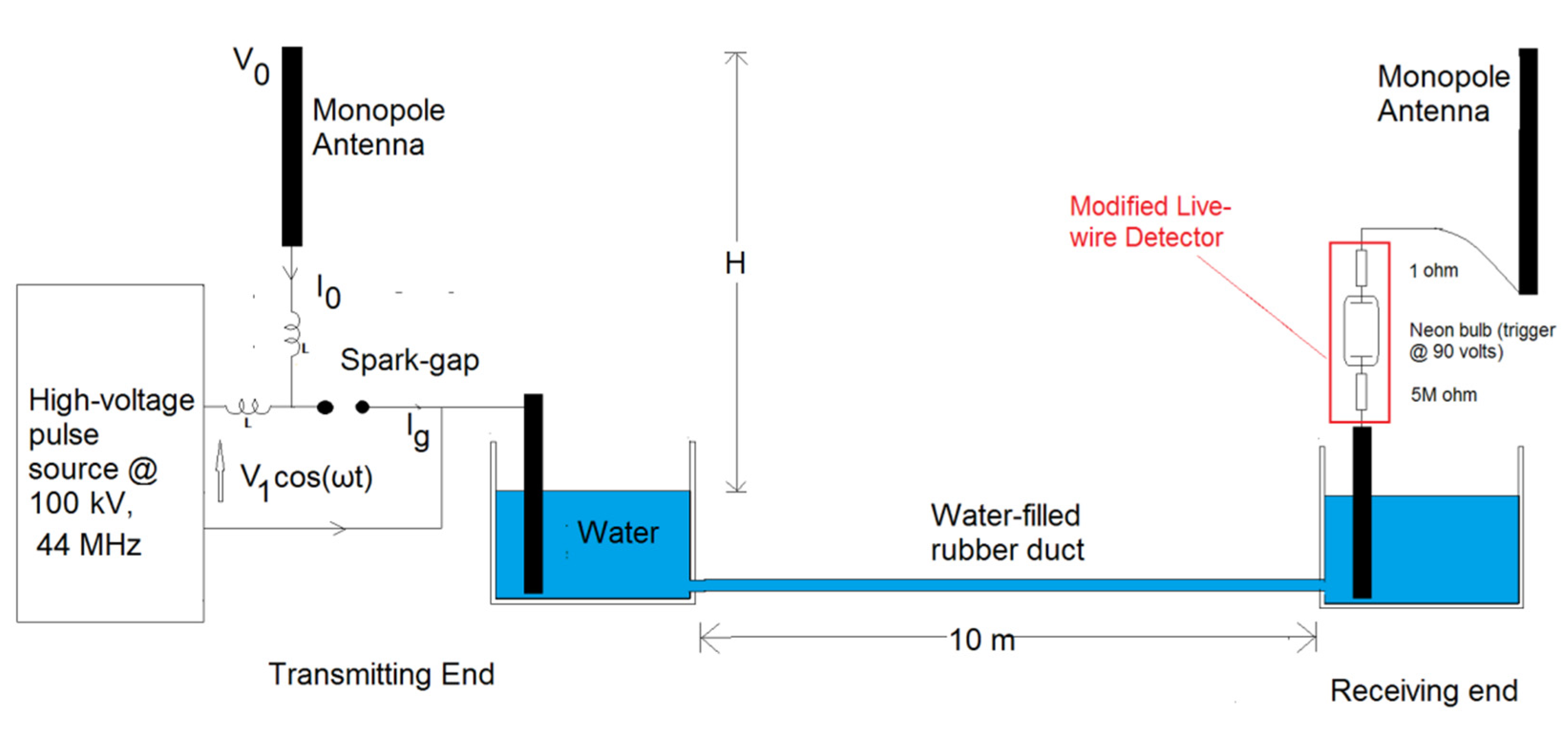
Figure 2 shows the experimental setup of this work. Instead of conducting the experiment on a real ocean, we used a water-filled rubber duct of various lengths to simulate the effects of an ocean. As Figure 2 shows, the 10 m long water filled rubber duct was terminated with two water-filled containers, one being labeled as the transmitting end and the other as the receiving end. This setup allows a high-voltage surface electromagnetic wave to be delivered from the transmitting end to the receiving end through a 10 m long water-filled rubber duct.
Upon detection of a power at the receiving end, the neon lamp in the modified live-wire detector will be on, and the two resistors connected to this neon lamp will consume the power. Of these two resistors, one was 1 ohm at the top of the modified live-wire detector. The voltage across this 1 ohm resistor was used to calculate the current flowing through the live-wire detector circuit. The power consumed by the 1 ohm was used to calculate the transmission efficiency.
The components in the experimental setup together with the experiments are separately discussed in more detail in the following paragraphs.

2.4.1. Transmitting End

At the transmitting end, the power source that drove the circuit was a 100 kV periodic pulse generator (See Figure 2). Its base frequency was 83 kHz but the spark gap released a mixture of harmonics of different resonant frequencies. The actual frequency of peak harmonics was found to be 44 MHz (See Figure 3b).
Driven by the 100 kV periodic pulsating source, the spark gap together with the monopole antenna formed a transmitter very similar to Marconi’s version of the spark gap transmitter [1,2,3,4,5,6] (See Figure 2). The left end of the spark gap was connected to the lower end of a vertical monopole antenna, while the right end of the spark gap was connected to a metal electrode submerged in water.
The Earth’s surface is covered with an electric field of 100 volts/m pointing downwards [37]. Suppose the atmospheric potential associated with the height H is V0. Since the antenna top has reached the height H, the body of the monopole antenna forms a conductive pathway to allow the positive ions at height H to flow towards the left end of the spark gap, thereby forming a current I0. Current I0 is a conductive current which carries charges. Whilst the current density of I0 is undeniably small, the high voltage mixing effect of the spark gap will amplify the harmonics enormously.
Let us assume that the current flowing through the spark gap is I g . Let us also assume that the inductance of the spark gap terminal and the inductance of the antenna are equal. The spark gap itself is a highly nonlinear device which can be modeled using the following polynomial equation:
I g = a 0 + a 1 V 1 + a 2 V 2 + a 3 V 3 + + a n V n
where the V is the voltage across the spark gap. The voltage across the spark gap can be modeled as
V = 1 2 V 0 + V 1 c o s ω t
where V 1 c o s ω t is the input voltage of the spark gap. By substituting V from Equation (18) back to Equation (17), we obtain:
I g = n = 1 n a n 2 n V 0 + V 1 c o s ω t n
Equation (19) can be broken down into multiple harmonics as well:
I g = I 0 + m = 1 I m c o s m ω t + ϕ m
where I 0 and all the harmonics become a function of V0 and V1.
For simplicity, let us say the value of n in Equation (19) is 3 as an example. By going through Equations (17)–(20), we obtain the total current
I g = I 0 + m = 1 3 I m c o s m ω t
where the DC current I 0 as well as the currents of the harmonics become:
I 0 = a 0 + a 1 V 0 2 + a 2 V 0 2 4 + a 3 V 0 3 8 + a 2 V 1 2 8 + 3 a 3 V 0 V 1 2 16  
I 1 = a 1 V 1 2 + a 2 V 0 V 1 2 + 3 a 3 V 0 2 V 1 8 + 3 a 3 V 1 3 32
I 2 = a 2 V 1 2 8 + 3 a 3 V 0 V 1 2 16
I 3 = a 3 V 1 3 32
In Equations (21)–(25), I 0 is the current along the body of the monopole antenna. I1 is the magnitude of the input current feeding the spark gap. I2 and I3 are the magnitudes of the harmonic waves being transmitted from the transmitting end to the receiving end.
In the absence of any monopole antenna, the surface wave along the interface was just an evanescent wave without any charge movement. According to our experimental outcome, this evanescent wave is not detectable at the receiving end.
However, after mounting the monopole antennas to both transmitting end and receiving end, the monopole antenna provides a conductive pathway for the positive ions at a higher altitude to flow towards medium 2. The nonlinear mixing effects of the spark gap enormously amplify the harmonics as revealed in Equations (21)–(25). V0 depends on the antenna height, while V1 is the magnitude of the input voltage feeding the spark gap. Based on the results of the above analysis, a high voltage input to the spark gap together with a highly suspended monopole antenna tends to have a positive effect on the transmission efficiency.

2.4.2. Receiving End

As explained in the Section 2.4.1, the surface waves which reach the receiving end carry charges from the spark gap as well as the atmospheric electric field. In this work, we harvested the energy from these waves using a device based on a modified live-wire detector (see the right side of Figure 2). The circuit contains a 6 M ohm resistor, a neon bulb, another 1 ohm resistor, and a monopole antenna connected in series. The neon bulb requires 90 volts to turn on. The monopole antenna was vertically mounted in a suspended place, with the top of the antenna being at least 1.5 m above the experimental setup.
The monopole antenna serves two purposes. In the AC sense, its capacitive end forms an AC ground of the circuit. In the DC sense, it forms a DC biasing node. Our Earth is enclosed in an electric field of 100 V/m [38,39,40,41]. The electrostatic voltage at a height of 1.5 m is equivalent to a DC voltage of 150 volts. Once the antenna top reaches this altitude, an atmospheric current will flow through the body of the modified live-wire detector circuit. This atmospheric current is too minute to do real work. However, the neon bulb requires only 70 volts to light, and it can operate with virtually no current. By biasing the neon bulb with the atmospheric field, the negative resistance inside the neon bulb will ring and self-generate a very large AC current, typically in excess of 1A. In the presence of a vertically mounted monopole antenna, this AC current will continue to oscillate and spill onto the resistors and the rest of the circuit. Typically, this current was found to be anywhere between 1 mA and 200 A.
The modified live-wire detector at the receiving end was used not only for detection, but also for measurement of the received power on the water surface. In this work, this device was used to measure the received power at the transmitting end ( P T ) and the receiving end ( P R ). The transmission efficiencies under different salt-concentrations can be calculated using the following equation:
E f f T = P R P T

3. Results

During the experimental work, the experimental setup as shown in Figure 2 was used to conduct the following experiments:
(a)
Basic functionality test.
(b)
An experiment testing for the feasibility of wireless power delivery to the receiving end when a tap water was used.
(c)
An experiment testing other materials as medium 2.
(d)
An experiment testing for wireless transmission of power under different salinity levels.
(e)
Transmission efficiency vs. distance test under different antenna heights.
This section reports the results of these experiments.

3.1. Basic Functionality Test

The goal of this basic functionality test was to make sure that the power at the transmitting end can propagate along a plastic/seawater interface and reach multiple loads at the receiving end. During this test, the experimental setup as proposed in Figure 2 was used throughout the experiment. The spark gap at the transmitting end was fed with a 100 kV pulse chain at 44 MHz. The water-filled plastic duct was heavily bent during the process of measurement. A seawater with a conductivity of 4 S was used as the material for medium 2. At the receiving end, three modified live-wire detectors were used simultaneously to capture the transmitted power.
The current at the 1 ohm resistor attached to the top of a randomly selected live-wire detectors was measured. This current represents the load current. This load current was found to be powerful enough to cause an electric shock to humans. It was also found that the load current was further increased by approximately 10–20% if the water-filled plastic duct was straightened.
It was also observed that the success of a wireless power delivery was subject to fulfillment of the following conditions:
(1)
The voltage of input feeding the spark gap was sufficiently high, typically above 20 kV.
(2)
The top of the monopole antenna in the transmitting end reached an altitude of at least 1 m above the experimental setup.
(3)
The top of each of the live-wire detectors was connected to a vertically mounted monopole antenna as stated in (2).
In each of the live-wire detectors, the voltage across the 1 ohm resistor represents the current flowing through the live-wire detector circuit. The measured current waveform and frequency spectrum are respectively included in Figure A1a. According to the measured results, the waveform of the current at the transmitting end was tainted with periodical vertical spikes induced by the high-voltage sparks from the spark gap.
Figure A1b shows the harmonic components detected using an endfire antenna pointing to the transmitting end. Using the peak search function of the spectrum analyzer, we managed to locate the maximum peak at around 44 MHz. The resonant frequencies of these harmonic peaks very close to 44 MHz dramatically moved from low to high periodically.
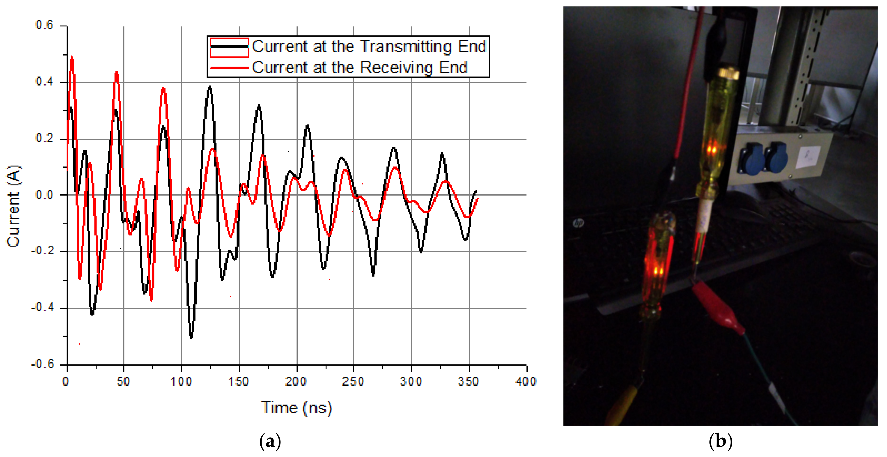
For the purpose of comparison, the waveforms of the detected currents at the transmitting end and the receiving end were plotted together in Figure 3a. As Figure 3a shows, the peak-to-peak currents for the transmitting end and the receiving end were respectively 2.04 A and 1.62 A, corresponding to an estimated transmission efficiency of 79.42%.
Figure 3b shows how multiple live-wire detectors were simultaneously lit at the receiving end. It should be noted that the top of each of these wire detectors was connected to vertically mounted monopole antenna.

3.2. Feasibility of Wireless Power Delivery to the Receiving End when a Tap Water Was Used

The objective of this test was to test for the feasibility of wireless power transfer if the conductivity of medium 2 is low. In this test, tap water was used as medium 2.
The DC conductivity of the tap water was about 60   μ S . A surface power was successfully received by more than one live-wire detectors at the receiving end; however, each of the neon bulbs was very dim.
The measured maximum peak-to-peak voltages across the 1 ohm resistor at the transmitting end and the receiving end were respectively 4.31 mV and 0.83 mV. Hence, the captured currents at the transmitting end and the receiving end were respectively 4.31 mA and 0.83 mA, as opposed to 2.04 A and 1.62 A obtained from the previous experiment.

3.3. Wireless Power Transfer under Different Salinity Levels

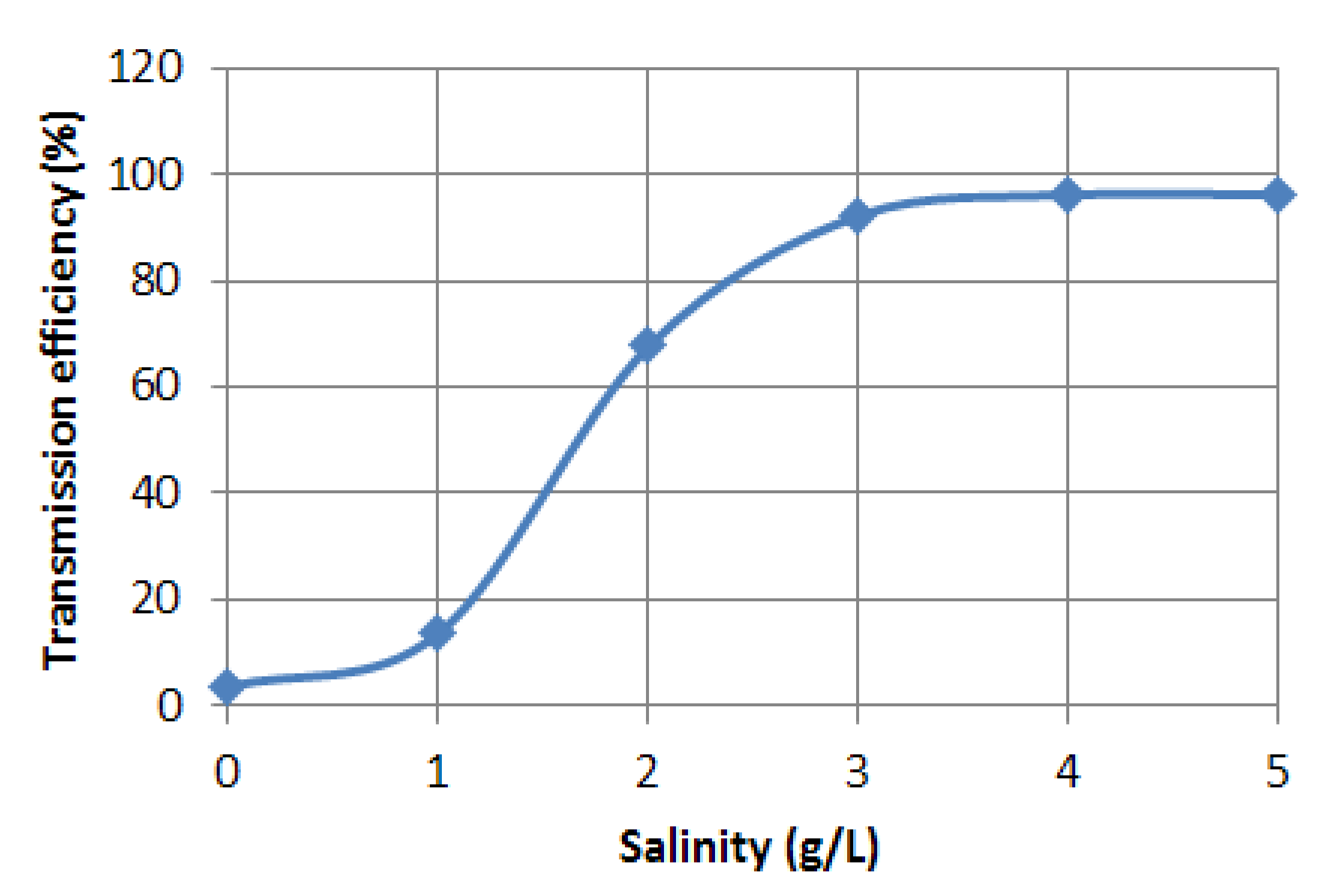
In this test, the salinity level of the water in the experimental setup was changed from zero to the seawater’s salinity level at 33 g/L. The transmission efficiency was measured under different salinity levels. Figure 4 shows the measured transmission efficiency as a function of salinity.
As Figure 4 shows, we only need 4 g/L of salt concentration to elevate the measured transmission efficiency to almost 100%.

3.4. Feasibility of Wireless Power Transfer when Non-Polar Solvents Were Used as Medium 2

The objective of this test was to test for the feasibility of wireless power transfer if a non-polar substance was used as medium 2. In this test, we tested the following materials for medium 2: an oil, an oil/detergent mixture, and a plastic coating of an electric cable. The measured results are summarized in Table 1.
As Table 1 shows, no power was detected at the receiving end or anywhere very close to the excitation source when oil was used as medium 2. No matter how high the excitation voltage was, there was no sign of wireless power transfer along the rubber/oil interface. We brought the modified live-wire detector very close to the excitation source, but the measured results remained the same. This finding suffices to prove that there was no observable near-field magnetic coupling in the experiment.
Table 1 suggests that power was detected at the receiving end if the oil was replaced with an oil/detergent mixture. Since the detergent solution was still a polar solvent under a high voltage stress, it was successfully detected by the live-wire detector.
However, a wireless power was successfully detected on the surface of an electric cable coating. The phenomenon demonstrates the feasibility of the proposed methodology to detect if a substance was polar or not.
The plastic coating of a current-carrying cable has a large loss tangent. Using the proposed methodology, this loss tangent was successfully detected along the contact interface under a high voltage stress.

3.5. Transmission Efficiency Versus Distance Test under Different Antenna Heights

The objective of this test was to measure the transmission efficiency under three different antenna heights, namely 1 m, 1.6 m, and 2 m. During this test, the proposed setup as shown in Figure 2 was used throughout the experiment. The transmitting end was excited with the spark transmitter at 44 MHz. The powers at the transmitting and receiving ends were individually measured using two oscilloscopes. Finally, the measured results were checked against the values calculated according to Marconi’s law of transmission.
The amount of power being transmitted at the transmitting end was approximately 196 watts.
Figure 5a–c respectively show the transmission efficiencies as a function of the propagation distance for an antenna height of 1 m, 1.6 m, and 2 m.
Table 2 shows a comparison between our estimated maximum propagation distance and the maximum signaling distance based on Marconi’s law of transmission. In our estimation, the propagation distance that led to the first maxima from the left axis was assumed to be 80% of maximum propagation distance. With this assumption, the antenna heights together with their respective maximum propagation distance were tabulated in Table 2.
The right-most column of Table 2 displays the maximum signaling distance estimated using Marconi’s law of transmission. By comparing the figures in the second and third columns of Table 2, it is obvious that our experimental outcome was consistent with Marconi’s law.

4. Discussion

Consistent with our simulated results and our theoretical prediction, the experimental outcome of this work has clearly demonstrated the fact that the interface between a low-loss non-polar medium and high-loss polar medium can support propagation of a wireless power if and only if the following conditions are satisfied:
(i)
The transmitting end and the receiving end are connected to a vertically mounted long monopole antenna.
(ii)
The transmitting end is excited with a high-voltage spark gap transmitter.
The original objective of this work was to simulate wireless power transfer over an actual ocean surface. The interface between air and the ocean surface is equivalent to the interface between a low-loss dielectric interface and a high-loss dielectric interface. The main difference between our experimental settings and the actual ocean surface lies in the wavenumber. The relative permittivity for water is 78 at microwave frequencies. If air is chosen to be the low-loss dielectric material, the wavenumber can be calculated using air as the low-loss dielectric is:
k = ω c ε r 1 + ε r
where ε r is the complex permittivity of the high-loss medium. However, a plastic is chosen to be the low-loss dielectric material, then the wavenumber becomes
k = ω c 2.2 ε r 2.2 + ε r
As predicted in Section 3.4, the high-loss dielectric medium which potentially fulfills the conditions dictated by (9) can be any conductive and polar substance. These materials cannot be pure water, oil, or any other non-polar substance with virtually no conductivity.
Unsalted tap water has a conductivity of 10 60   s / m . The plasma frequency of pure water is around 10 Hz. The plasma frequency is definitely lower than the frequency of the 100 kV pulsating source or any other of its harmonic components. Strictly speaking, it cannot be used as medium 2. According to inequality (9), if an unsalted tap water is used as medium 2, then it will be impossible to propagate a surface electromagnetic wave along the interface between air and the unsalted tap water.
However, water itself is a polar solvent. Under a high voltage stress, for example, its surface conductivity will increase [32]. The increase in the surface conductivity is equivalent to an increase in the plasma frequency. When the surface conductivity was increased to an extent that the condition of (9) is fulfilled, it will be partially possible to propagate a surface energy along the interface between air and the unsalted tap water. Therefore, with an unsalted water being used as medium 2, the feasibility of wireless power transfer very much depends on the degree of the high voltage stress [31,32,33,34,35,42].
Highly salted water such as a seawater is a perfect candidate material for medium 2. The plasma frequency of a seawater is around 250 GHz. The frequencies of the plasma source and its associated harmonic components are definitely lower than this plasma frequency. Below the plasma frequency, the permittivity of a plasma in a highly salted water is negative, thus fulfilling the conditions dictated by inequality (9).
However, fulfilling the conditions dictated by inequality (9) is just a part of the equation. Below the plasma frequency, most of the electromagnetic wave will be reflected by the plasma enclosing the interface, whilst a small portion of the surface electromagnetic energy continues to penetrate through and remains along the interface as an evanescent wave. This evanescent wave is unfortunately not a surface plasma wave in the sense that the wave itself unlikely carries any electric charge. Indeed, this may be the reason why no power was received at the receiving end without an antenna.
However, charges can be obtained from the atmospheric electrostatic field through a suspended metal objects such as the top of a monopole antenna. Equations (21)–(25) serve as a simplified proof that this evanescent wave can be loaded with electric charges with the help of an antenna. In the frequency spectrum, the frequency shifts of the resonant peaks from low to high are another indication of a rapid change in the permittivity [40]. Indeed, our experimental results have proven that the key to harvest an energy from this evanescent wave is a highly suspended monopole antenna.
According to the results presented in Section 3.4, a wireless power was detected on the contact surface of a polar substance under a high-voltage stress. However, no matter how high the voltage was, no wireless power was detected on the surface of a non-polar substance such as oil. Obviously, high voltage stress alone cannot elevate the surface conductivity of a non-polar substance, as opposed to the general findings in some other studies [31,32,33,34,35]. The experimental outcome as presented in Section 3.4 clearly contradicted the Zenneck’s theory of surface waves which propagate along an interface between two homogeneous media having different dielectric constants. Whilst wireless power transfer was the primary goal of this work, the findings associated with experiments as presented in Section 3.4 strongly suggest that the proposed methodology wireless power transfer can be used for identifying the polarity of a substance. More work needs to be done in this area.
At the time of this writing, long range wireless power is still believed to be an unresolved issue. However, our experimental results suffice to prove the following facts:
  • A high-voltage surface wave can be wirelessly transmitted along a curved or highly bent interface between a low-loss dielectric medium and a high-loss polar dielectric medium.
  • Even though tap water has very little conductivity, the high-voltage surface electromagnetic wave can propagate along the surface of a tap water and be delivered to multiple loads at the expense of the transmission efficiency.
  • It was possible to deliver a high-voltage surface electromagnetic wave to multiple loads, if and only if each of the loads is individually connected to a vertically mounted monopole antenna.
  • The salinity level of the water can enhance the transmission efficiency to a significant extent.
  • As a byproduct of this work, a live-wire detector can operate without any human contact if its metal top is connected to an antenna which reaches a great height or is suspended in mid-air.
  • As a byproduct of this work, the results of this work can be used to test if a substance is polar or not.
  • The transmission efficiencies as a function of the propagation distance have been measured under three different antenna heights. The measured results suggest that the correlation between the antenna height and the propagation distance in general obeys the Marconi’s law of transmission.
Wireless power transfer has been proven to be feasible along an air/metal interface [43], but this proof is not going to be enough to convince the world of the feasibility of long range wireless power transfer. For the first time, however, the results of this work have proven the feasibility of wireless power transfer on a surface of a tap water or salted water. The results of this work have strongly implicated the feasibility of wireless energy transfer between boats in an ocean. The results of this work further suggest that the methodology of this work can be used to detect if a substance is polar or non-polar.

5. Conclusions

We have experimentally and theoretically proven that a vertically mounted monopole antenna enables a high-voltage surface power to be wirelessly transmitted along the rubber/seawater interface to multiple loads. This interface can be flat, straight, curved, or heavily bent. On the other hand, our experimental results suggest that it is not possible to deliver a wireless power to the loads if the high-voltage surface power was replaced with a low-voltage electromagnetic wave, or if the load was disconnected from the vertically mounted monopole antenna. The outcome of our experiment also suggests that surface power cannot be wirelessly transmitted on the interface between air and a non-polar substance. The overall transmission efficiency was found to positively correlate with the water’s salinity levels. The antenna height was found to vary as the square root of the maximum transmission distance, consistent with Marconi’s law of transmission. The experimental outcome of this work can be used not only for wireless power transfer, but also for detection if a substance is a polar or non-polar.

Author Contributions

Conceptualization, L.W.Y.L.; Investigation, L.W.Y.L.; Methodology, L.W.Y.L.; Project administration, L.W.Y.L.; Resources, S.N.T.; Writing—original draft, L.W.Y.L. All authors have read and agreed to the published version of the manuscript.

Funding

This research received no external funding.

Institutional Review Board Statement

Not applicable.

Informed Consent Statement

Not applicable.

Data Availability Statement

Not applicable.

Conflicts of Interest

The authors declare no conflict of interest.

Appendix A

Figure A1 shows the photos of the measured power at the transmitting end.
Figure A1. Measured results of the power at the transmitting end: (a) Photo of the measured waveform of the current measured at the transmitting end. (b) Photo of the spectrum at frequencies in the neighborhood of the peak harmonic component.
Applsci 12 08751 g0a1

References

  1. Marconi, G. Wireless Telegraphic Communication; Nobel Lecture, December 11, 1909, Nobel Lectures, Physics 1901–1921; Elsevier: Amsterdam, The Netherlands, 1967. [Google Scholar]
  2. Marconi, G. The inventor of wireless telegraphy: A reply. Saturday Rev. 1902, 93, 556–557. [Google Scholar]
  3. Thompson, S.P. Wireless telegraphy: A rejoinder. Saturday Rev. 1902, 93, 598–599. [Google Scholar]
  4. Marconi, G. Wireless telegraphy. J. Inst. Elect. Eng. 1899, 28, 273–291. [Google Scholar]
  5. Bondyopadhyay, P.K. Guglielmo Marconi–The father of long distance radio communication, An engineer’s tribute. In Proceedings of the 25th European Microwave Conference, Bologna, Italy, 4–6 September 1995; pp. 879–885. [Google Scholar]
  6. Mazzinghi, P.; Pelosi, G. Enrico Fermi talks about Guglielmo Marconi [historical corner]. IEEE Antennas Propag. Mag. 2011, 53, 226–230. [Google Scholar] [CrossRef]
  7. Zenneck, J. Propagation of plane EM waves along a plane conducting surface. Annal. Phys. 1907, 28, 846–866. [Google Scholar] [CrossRef]
  8. Sommerfeld, A. Propagation of waves in wireless telegraphy. Annal. Phys. 1909, 28, 665–736. [Google Scholar] [CrossRef]
  9. Sommerfeld, A. Propagation of waves in wireless telegraphy. Annal. Phys. 1926, 81, 1135–1153. [Google Scholar] [CrossRef]
  10. Weyl, H. The propagation of electromagnetic waves over a plane conductor. Annal. Phys. 1919, 60, 481–500. [Google Scholar] [CrossRef]
  11. Van der Pol, B.; Niessen, K.F. Über die Ausbreitung elektromagnetischer Wellen über eine ebene Erde. Annal. Phys. 1930, 398, 273–294. [Google Scholar] [CrossRef]
  12. Wait, J.R. The ancient and modern history of EM ground-wave propagation. IEEE Antennas Propag. Mag. 1998, 40, 7–24. [Google Scholar] [CrossRef]
  13. Tamir, T.; Staiman, D. Nature and optimisation of the ground (lateral) wave excited by submerged antennas. Proc. IEEE 1966, 113, 1299–1310. [Google Scholar]
  14. Tesla, N. The True Wireless (Electrical Experimenter); Electrical Experimenter: New York, NY, USA, 1919. [Google Scholar]
  15. Liu, L.W.; Kandwal, A.; Eremenko, Z.E.; Zhang, Q. Open-ended voltage multipliers for wireless transmission of electric power. J. Microw. Power Electromagn. Energy 2017, 25, 187–204. [Google Scholar] [CrossRef]
  16. Tesla, N. The transmission of electrical energy without wires as a means for furthering peace. Elect. World Eng. 1905, 1, 21–24. [Google Scholar]
  17. Collin, R.E. Some observations about the near zone electric field of a hertzian dipole above a lossy earth. IEEE Trans. Antennas Propag. 2004, 52, 3133–3137. [Google Scholar] [CrossRef]
  18. Collin, R.E. Hertzian dipole radiating over a lossy earth or sea: Some early and late 20th-century controversies. IEEE Antennas Propag. Mag. 2004, 46, 64–79. [Google Scholar] [CrossRef]
  19. Petrillo, L.; Jangal, F.; Darces, M.; Montmagnon, J.-L.; H’elier, M. Negative permittivity Media Able to Propagate a Surface Wave. Prog. Electromagn. Res. 2011, 115, 1–10. [Google Scholar] [CrossRef]
  20. Liu, L.W.; Kandwal, A.; Shi, H.; Cheng, Q.S. Wireless Power Transfer using An RF Plasma. IEEE Access 2018, 6, 73905–73915. [Google Scholar] [CrossRef]
  21. Collin, R.E. Field Theory of Guided Waves; Chapter 11 Surface Waveguides; Wiley-IEEE Press: New York, NY, USA, 1990. [Google Scholar]
  22. Liu, L.W.; Zhang, Q.; Chen, Y.; Teeti, M.A.; Das, R. Wireless Energy Harvesting by Direct Voltage Multiplication on Lateral Waves From a Suspended Dielectric Layer. IEEE Access 2017, 5, 21873–21884. [Google Scholar] [CrossRef]
  23. Derrien, T.J.; Krüger, J.; Bonse, J. Properties of surface plasmon polaritons on lossy materials: Lifetimes, periods and excitation conditions. J. Opt. 2016, 18, 115007. [Google Scholar] [CrossRef]
  24. Tang, W.X.; Zhang, H.C.; Ma, H.F.; Jiang, W.X.; Cui, T.J. Concept, Theory, Design, and Applications of Spoof Surface Plasmon Polaritons at Microwave Frequencies. Adv. Opt. Mater. 2019, 7, 1800421. [Google Scholar] [CrossRef]
  25. Paloma Arroyo, H.; Fernández-Domínguez, A.I.; John, B.P.; Martín-Moreno, L.; Garcia-Vidal, F.J. Spoof Surface Plasmon Metamaterials; Cambridge University Press: Cambridge, UK, 2018; ISBN 9781108553445. [Google Scholar] [CrossRef]
  26. Fitzpatrick, R. Dielectric Constant of a Plasma. 2022. Available online: https://farside.ph.utexas.edu/teaching/em/lectures/node100.html (accessed on 6 May 2022).
  27. Calzada, M.D.; Moisan, M.; Gamero, A.; Sola, A. Experimental investigation and characterization of the departure from local thermodynamic equilibrium along a surface wave sustained discharge at atmospheric pressure. J. Appl. Phys. 1996, 80, 46. [Google Scholar] [CrossRef]
  28. Nhan, T.T.; Theu, L.T.; Tuan, L.; Viet, N.A. Drude-jellium model for the microwave conductivity of electrolyte solutions. J. Phys. Conf. Ser. 2018, 1034, 012006. [Google Scholar] [CrossRef]
  29. Shilov, I.Y.; Lyashchenko, A.K. The Role of Concentration Dependent Static Permittivity of Electrolyte Solutions in the Debye−Hückel Theory. J. Phys. Chem. B 2015, 119, 10087–10095. [Google Scholar] [CrossRef]
  30. Li, S.; Li, S.; Anwar, S.; Tian, F.; Lu, W.; Hou, B. Determination of Microwave Conductivity of Electrolyte Solutions from Debye-Drude Model. In Proceedings of the Progress in Electromagnetics Research Symposium, Guangzhou, China, 25–28 August 2014. [Google Scholar]
  31. Salem, A.A.; Lau, K.Y.; Abdul-Malek, Z.; Zhou, W.; Al-Ameri, S.; Al-Gailani, S.A.; Rahman, R.A. Investigation of High Voltage Polymeric Insulators Performance under Wet Pollution. Polymers 2022, 14, 1236. [Google Scholar] [CrossRef] [PubMed]
  32. Raymond, R. Re: What Is the Effect of High Voltage on Dielectric Materials? 2014. Available online: https://www.researchgate.net/post/What-is-the-effect-of-high-voltage-on-dielectric-materials/53a03be5d4c11862098b4729/citation/download (accessed on 6 May 2022).
  33. Wu, K.; Okamoto, T.; Suzuoki, Y. Effects of discharge area and surface conductivity on partial discharge behavior in voids under square voltages. IEEE Trans. Dielectr. Electr. Insul. 2007, 14, 461–470. [Google Scholar] [CrossRef]
  34. Lasabi, O.A. Performance of Insulators under HVDC Stress. Ph.D. Thesis, University of Kwazulu-Natal, Durban, South Africa, August 2018. [Google Scholar]
  35. Browne, T.E., Jr. Circuit Interruption: Theory and Techniques; Marcel Dekker, Inc.: New York, NY, USA, 1984. [Google Scholar]
  36. Unknown Editor. Microwaves101.com. Available online: https://www.microwaves101.com/encyclopedias/skin-depth (accessed on 14 June 2022).
  37. Liu, L.W.Y.; Zhang, Q.; Chen, Y. Harvesting atmospheric ions using surface electromagnetic wave technologies. J. Adv. Technol. Innov. 2017, 2, 99104. [Google Scholar]
  38. Chalmers, J.A. Atmospheric Electricity; Pergamon Press: London, UK, 1957. [Google Scholar]
  39. Brenni, P. Prometheus’ Tools: Instruments and Apparatus Used in Atmospheric Electricity Research and Experiments. Trans. Am. Philos. Soc. 2009, 99, 230–255. [Google Scholar]
  40. Kandwal, A.; Nie, Z.; Igbe, T.; Li, J.; Liu, Y.; Liu, L.W.; Hao, Y. Surface Plasmonic Feature Microwave Sensor With Highly Confined Fields for Aqueous-Glucose and Blood-Glucose Measurements. IEEE Trans. Instrum. Meas. 2021, 70, 1–9. [Google Scholar] [CrossRef]
  41. Kittel, C. Introduction to Solid State Physics, 6th ed.; John Wiley: New York, NY, USA, 1986. [Google Scholar]
  42. Nomura, S.; Kageura, M.; Toyota, H.; Mukasa, S. G0601-5-3 Discharge Characteristics of High-Frequency In-Liquid Plasma. Proc. JSME Annu. Meet. 2009, 3, 49–50. [Google Scholar] [CrossRef]
  43. Oruganti, S.K.; Liu, F.; Paul, D.; Liu, J.; Malik, J.; Feng, K.; Kim, H.; Liang, Y.; Thundat, T.; Bien, F. Experimental Realization of Zenneck Type Wave-based Non-Radiative, Non-Coupled Wireless Power Transmission. Sci. Rep. 2020, 10, 925. [Google Scholar] [CrossRef] [Green Version]
Figure 1. (a) Cross-sectional view of an interface between a lossless dielectric material and a lossy dielectric material. (b) Excitation of a surface electromagnetic wave on a monopole antenna partially submerged in a seawater, by a 100 kV pulsating source at 44 MHz. (c) Simulated surface electromagnetic wave as a result of the monopole antenna setup in (b). (d) Simulated S1,1 parameters of the setup in (b).
Applsci 12 08751 g001
Figure 2. Experimental setup on wireless power transfer.
Applsci 12 08751 g002
Figure 3. Results of the basic functionality test. (a) Waveforms of the currents harvested at the transmitting end and the receiving end. (b) Photo showing how the surface power was received by multiple loads.
Applsci 12 08751 g003
Figure 4. Measured transmission efficiency as a function of salinity.
Applsci 12 08751 g004
Figure 5. Transmission efficiency as a function of transmission distance: (a) when the antenna height was 1 m; (b) when the antenna height was 1.6 m; (c) when the antenna height was 2 m.
Applsci 12 08751 g005
Table 1. Measured results when a non-water substance was used as medium 2.
Polarity of the
Substance
Detection of Power When the Modified Live-Wire Detector Was in Contact with Medium 2Detection Near-Field
Magnetic Coupling
Transmission Range between the Detection Point and the
Excitation Source
OilNon-polarNoNone5 cm
Oil Mixed with DetergentPolarYesNone1 m
Coating of a Current-Carrying Electric CablePolarYesNone1 m
Table 2. Comparison between our estimated maximum propagation distance and the maximum signaling distance based on Marconi’s law of transmission.
Antenna Height (m)Estimated Maximum Propagation Distance (m)Maximum Signaling Distance (m) Based on Marconi’s Law of Transmission
12.52.5
1.67.56.4
21010
Publisher’s Note: MDPI stays neutral with regard to jurisdictional claims in published maps and institutional affiliations.