Article

High-Efficiency Characterization of Optical Vortices with Arbitrary State of Polarization Using Straight-Line and Parabolic-Line Polarization Gratings

1
Department of Electrical Engineering, Nagaoka University of Technology, 1603-1 Kamitomioka, Nagaoka 940-2188, Niigata, Japan
2
Japan Science and Technology Agency (JST), Core Research for Evolutional Science and Technology (CREST), Chiyoda-ku, Tokyo 102-0076, Japan
3
Department of Applied Chemistry, University of Hyogo, 2167 Shosha, Himeji 671-2280, Hyogo, Japan
*
Author to whom correspondence should be addressed.
Appl. Sci. 2022, 12(17), 8768; https://doi.org/10.3390/app12178768
Submission received: 20 July 2022 / Revised: 29 August 2022 / Accepted: 29 August 2022 / Published: 31 August 2022
(This article belongs to the Special Issue Photo-Responsive Materials and Devices)

Abstract

:

Featured Application

Optical communication, Optical manipulation, Optical processing.

Abstract

An optical system consisting of a straight-line polarization grating (SPG) and two parabolic-line polarization gratings (PPGs) is presented for the characterization of optical vortices (OVs) with arbitrary states of polarization (SoPs). The PPG is capable of converting an OV with a specific SoP into a bright bar-like spot with 100% efficiency. The number of dark lines and their orientation respectively correspond to the magnitude and sign of topological charge (TC) of the incident OV, thereby enabling characterization of OVs with high efficiency. Furthermore, on combining an SPG with PPGs, the present system can characterize the TC of incident OVs regardless of their SoP. The feasibility of the system was demonstrated in experiments using gratings fabricated by applying the photoalignment method and employing films of a photo-crosslinkable polymer liquid crystal. The experimentally obtained efficiency is 70.2%. We furthermore demonstrate the system’s capability to characterize polarization vortices.

1. Introduction

Optical vortices (OVs), which have a helical wavefront and phase singularity at the optical axis, have been attracting attention in recent decades because of their unique optical properties including orbital angular momentum and a dark hole at the phase singularity [1]. The helical phase term of an OV is expressed as exp [iℓθ], where θ denotes the azimuth angle, and the topological charge (TC) that corresponds to the phase ramp of the OV. Because the angular momentum and the size of the dark hole of OVs depend on the TC, their characterization is important for applications in, for example, optical communication [2], optical processing [3], and optical manipulation [4]. Diverse approaches have been proposed so far for their characterization, such as interferometry [5], diffraction from various apertures [6,7,8,9], and use of a robust mode converter [10], a hologram [11] or mode sorter [12].
Recently, Amiri et al. proposed a method using parabolic-line gratings for OV characterization [13]. Its basic principle of operation is based on the astigmatic transformation of the beam as it passes through a cylindrical lens. The lens transforms an axially symmetric OV into an astigmatic beam with a strongly deformed vortex core near the focal plane [14,15,16]. The parabolic-line grating performs the astigmatic transformation on modes of one side of the signed diffraction orders. This method is effective in view of optical throughput because over a given diffraction order (specifically, the +1st order diffraction spot), all of the beam’s energy is transferred into a beam that forms a bright bar-like spot. In addition, its ease of use is advantageous because it is not sensitive to the relative location of the beam axis and the grating center. Moreover, by combining the parabolic-line amplitude and phase gratings, a near 50% diffraction efficiency for diffracted light of +1st order has been indicated from the theory. However, in view of applications, the diffraction efficiency of the spot for OV characterization should ideally reach 100%. Although a phase-type spatial light modulator (SLM) only acts on linearly polarized light for which the polarization azimuth aligns along the director of the liquid crystal layer of the SLM, a parabolic-line grating cannot be used for arbitrary states of polarization (SoPs). To overcome this problem, we proposed an alternative method that exploits two kinds of polarization gratings, called straight-line polarization gratings (SPGs) and parabolic-line polarization gratings (PPGs). Based on the way the PPG functions, our method can characterize the TC of incident OVs with 100% efficiency. Furthermore, by adding an SPG, the method can be used regardless of the SoP of the incident OV.

2. Operating Principle of Our OV Characterizer

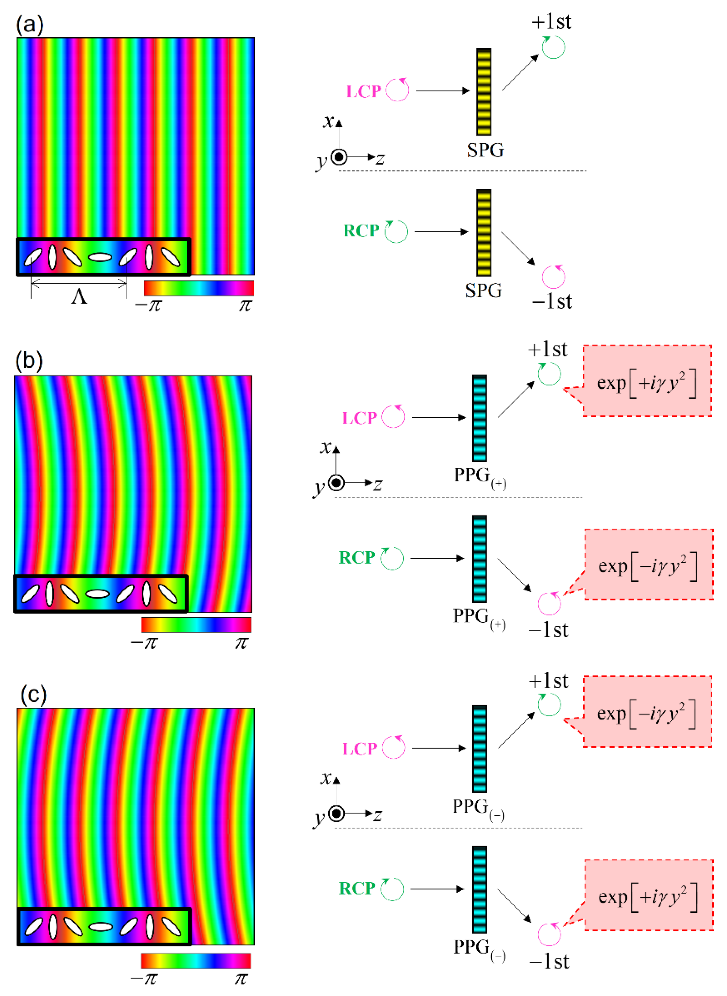
First, we briefly describe the operating principle used in characterizing OVs with arbitrary SoPs. This system consists of an SPG, two PPGs, and an imaging sensor (Figure 1). The SPG and PPG are Pancharatnum–Berry phase elements that imprint space-variant anisotropic patterns on elements [17,18,19,20,21]. The PPG is divided into two parts PPG(+) and PPG(−). The slow axes of the PPG(+) and PPG(−) are both rotated counter-clockwise along the vector direction of the grating, whereas the parabolic lines are inverted (Figure 2). Using the Jones matrix formula, the functions of the SPG and the two PPGs are written as
T S = cos Γ 1 0 0 1 + 1 2 sin Γ 2 e i 2 π x Λ i 1 1 i + 1 2 sin Γ 2 e i 2 π x Λ i 1 1 i ,
T P 1 = cos Γ 1 0 0 1 + 1 2 sin Γ 2 e i 2 π x Λ + ϕ y i 1 1 i + 1 2 sin Γ 2 e i 2 π x Λ + ϕ y i 1 1 i ,  
T P 2 = cos Γ 1 0 0 1 + 1 2 sin Γ 2 e i 2 π x Λ ϕ y i 1 1 i + 1 2 sin Γ 2 e i 2 π x Λ ϕ y i 1 1 i ,  
where Γ = 2 π Δ n d / λ denotes the retardation of the SPG and PPGs, Δ n , d , Λ , and λ denote the birefringence, thickness of the polarization grating, grating pitch, and wavelength, respectively. The phase angle ϕ y = γ y 2 describes the parabolic phase pattern in the same manner as the curvature of a cylindrical lens. Here, γ is a curvature coefficient of cylindrical phase term. With Jones vectors L = 1 ,   i / 2 and R = 1 , i / 2 for the left- and right-handed circular polarizations (LCP and RCP), the beam output from the straight-line and PPGs are expressed as
E S L = T S L = cos Γ L + 1 2 sin Γ 2 e i 2 π x Λ R ,  
E S R = T S R = cos Γ R + 1 2 sin Γ 2 e i 2 π x Λ L ,  
E P + L = T P 1 L = cos Γ L + 1 2 sin Γ 2 e i 2 π x Λ + ϕ y R ,  
E P + R = T P 1 R = cos Γ R + 1 2 sin Γ 2 e i 2 π x Λ + ϕ y L .  
E P L = T P 2 L = cos Γ L + 1 2 sin Γ 2 e + i 2 π x Λ ϕ y R ,  
E P R = T P 2 R = cos Γ R + 1 2 sin Γ 2 e i 2 π x Λ ϕ y L ,  
where E S L , E S R , E P + L , E P + R , E P L , and E P R represent the Jones vectors of the output beams from the SPG, PPG(+), and PPG(−) for LCP and RCP incident beams, respectively. From these equations, the SPG and PPG both show 100% diffraction efficiency for which the retardation is Γ = π . According to Equations (4) and (5), when LCP/RCP light is incident on the SPG, the transmitted light diffracts toward the direction of the +1st/−1st order mode, depending on the handedness of the circular polarization [see Figure 2a]. Similarly, from Equations (6) and (7) for the PPG(+), the transmitted light is converted to cylindrically spreading/focusing light and diffracts toward the +1st/−1st order mode direction, depending on the handedness of the circular polarization [Figure 2b]. From Equations (8) and (9) for the PPG(−), the transmitted light is also converted to cylindrically focusing/spreading light but diffracts toward the +1st/−1st order mode direction, depending on the handedness of the circular polarization [Figure 2c].
Given the operations of the SPG and PPGs, we now describe the characterization principle of the TC. We consider the scenario of an arbitrary polarized OV with a TC of incident on the setup for our characterizer (Figure 1). Initially, an arbitrary polarized OV can be treated as a superposition of LCP and RCP OV components with a TC of . These two OV components are first incident on the SPG and diffracted in the direction of the +1st and −1st order modes with the handedness of their polarization flipped. RCP and LCP OVs are incident on the PPG(+) and PPG(−), respectively. The PPG(+) and PPG(−) diffract incident OVs, the wavevectors of which are aligned parallel to each other. Furthermore, both PPGs introduce a parabolic phase exp i ϕ y , so that cylindrical focusing occurs at the focal length positions of the PPG(+) and PPG(−). When OVs are cylindrically focused by the cylindrical lens, a bright bar-like spot appears in the focal plane [14,15,16]. The number of dark lines in this bar-like spot yields the magnitude of the TC; its sign is determined from the angle of the spot, being either +45° or −45°. Therefore, using an imaging camera, the TC of any incident OV can be determined from its beam profile.
Our system can determine the TC of the LCP and RCP components of incident light without any optical loss because the SPG and PPGs have a diffraction efficiency of 100%. In addition, because SoPs can be treated as superpositions of LCP and RCP components, our system can be used for characterizing OVs with arbitrary SoPs. This function is realized by assembling a combination of a SPG and PPGs. The PPG(+)/PPG(−) can only determine the TC value for only RCP/LCP light. From Equations (6) and (9), we find that the LCP/RCP light passing through the PPG(+)/PPG(−) is cylindrically spread. In this case, a bright bar-like spot is not obtained and therefore we cannot determine the TC of the incident OV. To solve this problem, we introduce a single SPG to individually convert the LCP and RCP components of incident OV into a bright bar-like spot using the PPGs. As a result, our system can determine the TC of incident OV regardless of its SoP.
We note that our system also can determine the TC of a polarization vortex (PV) such as a radially polarized beam [22]. The Jones vector of a PV is expressible as
P V = cos p θ sin p θ = 1 2 e i p θ R + 1 2 e i p θ L ,  
where p denotes the TC of the PV, which corresponds to the rotational symmetry of the polarization pattern around the optical axis. From Equation (10), we find that the PV is a superposition of RCP and LCP OVs with = p and = p . Therefore, when the PV is incident on the system (Figure 1), the patterns obtained in the focal plane are different bar-like spots. From their patterns, we can also determine the TC of each PV.

3. Experimental Methods

To verify the feasibility of the operating principle, we performed an experiment in which we used a photo-crosslinkable polymer liquid crystal (PCLC) film from which the SPG and PPGs were made [23]. Anisotropic patterns can be imprinted in the PCLC films by recording a polarization hologram from LCP and RCP light for which one beam has a parabolic-shaped wavefront. Figure 3 shows the experimental setup for fabricating the PPGs. As light source, we used a diode-pumped solid-state (DPSS) laser (0355-05-01-0020-700, Cobolt AB) (Solna, Sweden) with an operating wavelength of 355 nm. The SoPs of the two interfering beams were converted to LCP and RCP using quarter-wave and half-wave plates (QWP and HWP). A cylindrical lens was inserted in one of the optical paths before the sample plane to change the wavefront into a parabolic shape. The PPG(+) and PPG(−) were respectively fabricated by interchanging the handedness of the circular polarization between the parabolic and plane wavefront beams. The focal length of the cylindrical lens is 1 m. Fabrication details of the polarization gratings out of PCLC film are described in our previous papers [20,24]. We fabricated PPGs with a grating pitch of 3.73 μm and a diffraction efficiency of 97.3%. We configured the SPG by eliminating the cylindrical lens (Figure 3). The effective diameter of the aperture of the fabricated polarization gratings is approximately 6 mm.
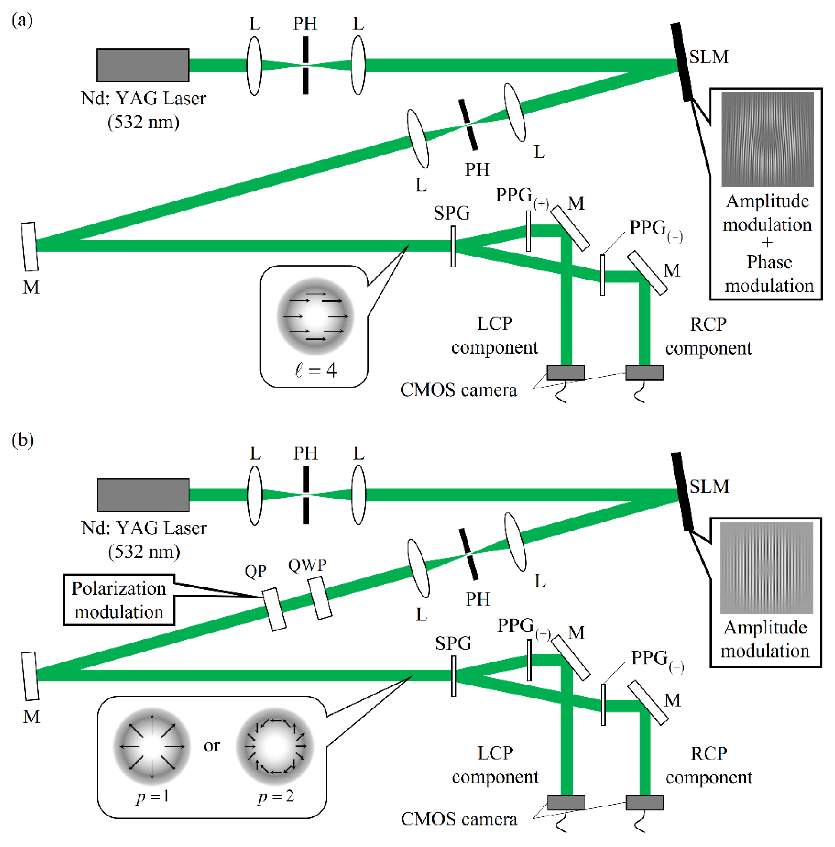
We next assembled an optical setup for demonstrating the OV characterization using a SPG and two PPGs [Figure 4a]. In this setup, a beam emitted from the Nd:YAG laser (operating at 532 nm) was first expanded in diameter and reflected onto a SLM (SLM-200; Santec Inc.) (Aichi, Japan). The amplitude and phase distributions of the reflected light were both modulated using a hologram projected onto the SLM; an OV is thus generated as diffracted light. One diffraction spot from the SLM is filtered by a pinhole and then directed onto the system of SPG and PPGs. The LCP and RCP components divided by the SPG are cylindrically focused by the PPG(+) and PPG(−), respectively. A beam profile of each spot is imaged using a CMOS camera. In this experiment, we generated a LP OV with = 4 . We also demonstrated the feasibility of PV characterization by generating a PV using the SLM and q-plate (QP) [Figure 4b]. The QP is a space-variant HWP, which converts a linearly polarized beam into a PV [25,26,27]. With this setup, we generated PVs with p = 1 and p = 2 using two kinds of QPs made of a liquid crystal film.

4. Results and Discussion

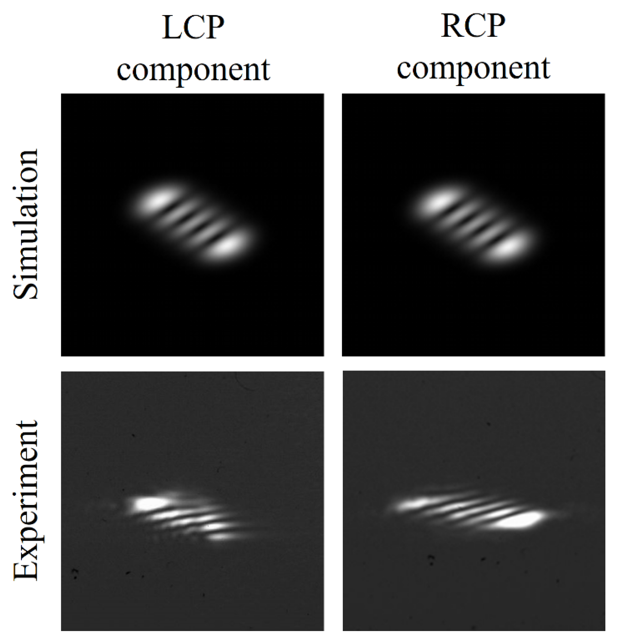
Figure 5 shows numerically simulated and experimentally observed beam profiles at the two detection positions for incident LP OVs with = 4 . We recorded bright bar-like spots at both detection positions. As described in the theory section, the two detection positions correspond to the LCP and RCP components of the incident beam. From the number of dark lines, we found that the LCP and RCP components of the incident beam both have TC of = 4 . From this information, we are able to characterize the incident beam as an OV with = 4 . In addition, the total energy at the two detection positions was measured to 70.2% As described in the Section 2, our system can realize 100% optical throughput in ideal. We can consider that this deterioration between the theory and experiment was caused by the imperfection and the Fresnel reflection of the SPG and PPGs, so that we can improve the optical throughput by adjusting the retardation of SPG and PPGs and, introducing anti-reflection coating. If we only use a single PPG for LP OV characterization, the optical throughput is limited to 50% because one of the circularly polarized components is cylindrically spread after passing through the PPG [Figure 2b,c]. The result shown in Figure 5 proves that both circular polarization components are cylindrically focused by the setup with one SPG and two PPGs. Therefore, even if the incident OV has an arbitrary SoP, our system can characterize the TC value of the incident OV with high optical throughput. In addition, if we measure the ratio of the beam intensities at the two detection positions, we can reconstruct the ellipticity of the incident OV.
We can find the fading or twisting bright spots, especially at the edge of the experimentally obtained results shown in Figure 5 and Figure 6. We consider this distortion to be caused by the initial amplitude distribution of OV before the incident on the proposed system. Due to the accuracy of our experimental setup for generating OV, the measured OV does not have a doughnut-shaped amplitude distribution which is completely matched with the pure Laguerre Gaussian beam. By measuring the number of dark lines along the centerline perpendicular to the dark line orientation, we would mitigate this impact.
Since the SPG and PPG is made of polymer liquid crystal, its birefringence and alignment pattern is almost immune to the temperature and vibration within the room temperature. As a result, the observed beam profiles in the experiment are stable for environmental fluctuation.
From numerically simulated and experimentally obtained beam profiles at the two detection positions for an incident PV with (a) p = 1 and (b) p = 2 [Figure 6a,b], we found that the LCP and RCP components of the incident beam have TC values of Figure 6a ( L = 1 , R = 1 ) and Figure 6b ( L = 2 , R = 2 ), respectively. From this information, we characterize the incident beam as PV with (a) p = 1 and (b) p = 2 . These results indicate that our system is highly efficient not only as an OV characterizer but also as PV characterizer. Furthermore, our system can characterize vector vortex beams, which have both phase and polarization singularity. Because these beams can be decomposed into LCP and RCP OVs with L R , the two detection positions show bright bar-like spots that differ in their number of dark lines.

5. Conclusions

We proposed a method for characterizing OVs that uses two kinds of polarization gratings. The proposed system can characterize the OV with high optical throughput even if the incident OV has an arbitrary SoP. By comparing the striped diffraction patterns at the two detection positions, the proposed setup also can characterize PVs. The feasibility was demonstrated in experiments using SPGs and PPGs made of PPLC film. Our system can be employed to characterize both OV and PV in applications relating to optical communication, optical processing, and optical manipulation.

Author Contributions

Conceptualization, M.S.; Data curation, T.Y. and K.N.; Formal analysis, T.Y.; Investigation, T.Y.; Project administration, H.O.; Resources, N.K.; Supervision, M.S., T.S. and H.O.; Writing—original draft, M.S. All authors have read and agreed to the published version of the manuscript.

Funding

This research received no external funding.

Data Availability Statement

Data underlying the results presented in this paper are not publicly available at this time but may be obtained from the authors upon reasonable request.

Acknowledgments

This work was supported by Japan Science and Technology Agency (CREST JPMJCR2101).

Conflicts of Interest

The authors declare no conflict of interest.

References

  1. Franke-Arnold, S.; Allen, L.; Padgett, M. Advances in optical angular momentum. Laser Photon. Rev. 2008, 2, 299–313. [Google Scholar] [CrossRef]
  2. Gibson, G.; Courtial, J.; Padgett, M.J. Free-space information transfer using light beams carrying orbital angular momentum. Opt. Express 2004, 12, 5448–5456. [Google Scholar] [CrossRef] [PubMed]
  3. Toyoda, K.; Takahashi, F.; Takizawa, S.; Tokizane, Y.; Miyamoto, K.; Morita, R.; Omatsu, T. Transfer of Light Helicity to Nanostructures. Phys. Rev. Lett. 2013, 110, 143603. [Google Scholar] [CrossRef] [PubMed]
  4. Gahagan, K.T.; Swartzlander, G.A., Jr. Optical vortex trapping of particles. Opt. Lett. 1996, 21, 827–829. [Google Scholar] [CrossRef] [PubMed]
  5. Harris, M.; Hill, C.A.; Tapster, P.R.; Vaughan, J.M. Laser modes with helical wave fronts. Phys. Rev. A 1994, 49, 3119–3122. [Google Scholar] [CrossRef] [PubMed]
  6. Guo, C.S.; Lu, L.L.; Wang, H.T. Characterizing topological charge of optical vortices by using an annular aperture. Opt. Lett. 2009, 34, 3686–3688. [Google Scholar] [CrossRef] [PubMed]
  7. Hickmann, J.M.; Fonseca, E.J.S.; Soares, W.C.; Chavez-Cerda, S. Unveiling a truncated optical lattice associated with a triangular aperture using light’s orbital angular momentum. Phys. Rev. Lett. 2010, 105, 053904. [Google Scholar] [CrossRef] [PubMed]
  8. De Araujo, L.E.; Anderson, M.E. Measuring vortex charge with a triangular aperture. Opt. Lett. 2011, 36, 787–789. [Google Scholar] [CrossRef]
  9. Hebri, D.; Rasouli, S.; Dezfouli, A.M. Theory of diffraction of vortex beams from structured apertures and generation of elegant elliptical vortex Hermite-Gaussian beams. J. Opt. Soc. Am. A 2019, 36, 839–852. [Google Scholar] [CrossRef]
  10. Zhou, J.; Zhang, W.; Chen, L. Experimental detection of high-order or fractional orbital angular momentum of light based on a robust mode converter. Appl. Phys. Lett. 2016, 108, 111108. [Google Scholar] [CrossRef]
  11. Moreno, I.; Davis, J.A.; Pascoguin, B.M.; Mitry, M.J.; Cottrell, D.M. Vortex sensing diffraction gratings. Opt. Lett. 2009, 34, 2927–2929. [Google Scholar] [CrossRef]
  12. Berkhout, G.C.; Lavery, M.P.; Courtial, J.; Beijersbergen, M.W.; Padgett, M.J. Efficient sorting of orbital angular momentum states of light. Phys. Rev. Lett. 2010, 105, 153601. [Google Scholar] [CrossRef]
  13. Amiri, P.; Dezfouli, A.M.; Rasouli, S. Efficient characterization of optical vortices via diffraction from parabolic-line linear gratings. J. Opt. Soc. Am. B 2020, 37, 2668–2677. [Google Scholar] [CrossRef]
  14. Bekshaev, A.Y.; Soskin, M.S.; Vasnetsov, M.V. Transformation of higher-order optical vortices upon focusing by an astigmatic lens. Opt. Commun. 2004, 241, 237–247. [Google Scholar] [CrossRef]
  15. Singh, R.K.; Senthilkumaran, P.; Singh, K. Influence of astigmatism and defocusing on the focusing of a singular beam. Opt. Commun. 2006, 270, 128–138. [Google Scholar] [CrossRef]
  16. Denisenko, V.; Shvedov, V.; Desyatnikov, A.S.; Neshev, D.N.; Krolikowski, W.; Volyar, A.; Soskin, M.; Kivshar, Y.S. Determination of topological charge of polychromatic optical vortices. Opt. Express 2009, 23374–23379. [Google Scholar] [CrossRef]
  17. Todorov, T.; Nikolova, L.; Tomova, N. Polarization holography. 2: Polarization holographic gratings in photoanisotropic materials with and without intrinsic birefringence. Appl. Opt. 1984, 23, 4588–4591. [Google Scholar] [CrossRef]
  18. Davis, J.A.; Adachi, J.; Fernandez-Pousa, C.R.; Moreno, I. Polarization beam splitters using polarization diffraction gratings. Opt. Lett. 2001, 26, 587–589. [Google Scholar] [CrossRef]
  19. Bomzon, Z.; Biener, G.; Kleiner, V.; Hasman, E. Space-variant Pancharatnam-Berry phase optical elements with computer-generated subwavelength gratings. Opt. Lett. 2002, 27, 1141–1143. [Google Scholar] [CrossRef]
  20. Ono, H.; Emoto, A.; Kawatsuki, N.; Takahashi, F.; Hasegawa, T. Highly stable polarization gratings in photocrosslinkable polymer liquid crystals. J. Appl. Phys. 2003, 94, 1298–1303. [Google Scholar] [CrossRef]
  21. Escuti, M.J.; Oh, C.; Sanchez, C.; Bastiaansen, C.; Broer, D.J. Simplified spectropolarimetry using reactive mesogen polarization gratings. Proc. SPIE 2006, 6302, 630207. [Google Scholar]
  22. Zhan, Q. Cylindrical vector beams: From mathematical concepts to applications. Adv. Opt. Photon. 2009, 1, 1–57. [Google Scholar] [CrossRef]
  23. Kawatsuki, N.; Goto, K.; Kawakami, T.; Yamamoto, T. Reversion of alignment direction in the thermally enhanced photo orientation of photo-cross-linkable polymer liquid crystal films. Macromolecules 2002, 35, 706–713. [Google Scholar] [CrossRef]
  24. Momosaki, R.; Ashikawa, K.; Sakamoto, M.; Noda, K.; Sasaki, T.; Kawatsuki, N.; Ono, H. Incident angle dependence-reduced polarization grating performed by using optically biaxial polymer liquid crystal. Opt. Lett. 2019, 44, 5929–5932. [Google Scholar] [CrossRef] [PubMed]
  25. Bomzon, Z.; Kleiner, V.; Hasman, E. Formation of radially and azimuthally polarized light using space-variant subwavelength metal stripe gratings. Appl. Phys. Lett. 2001, 79, 1587–1589. [Google Scholar] [CrossRef]
  26. Niv, A.; Beiner, G.; Kleiner, V.; Hasman, E. Manipulation of the Pancharatnam phase in vectorial vortices. Opt. Express 2006, 14, 4208–4220. [Google Scholar] [CrossRef] [PubMed]
  27. Cardano, F.; Karimi, E.; Slussarenko, S.; Marrucci, L.; de Lisio, C.; Santamato, E. Polarization pattern of vector vortex beams generated by q-plates with different topological charge. Appl. Opt. 2012, 51, C1–C6. [Google Scholar] [CrossRef] [PubMed] [Green Version]
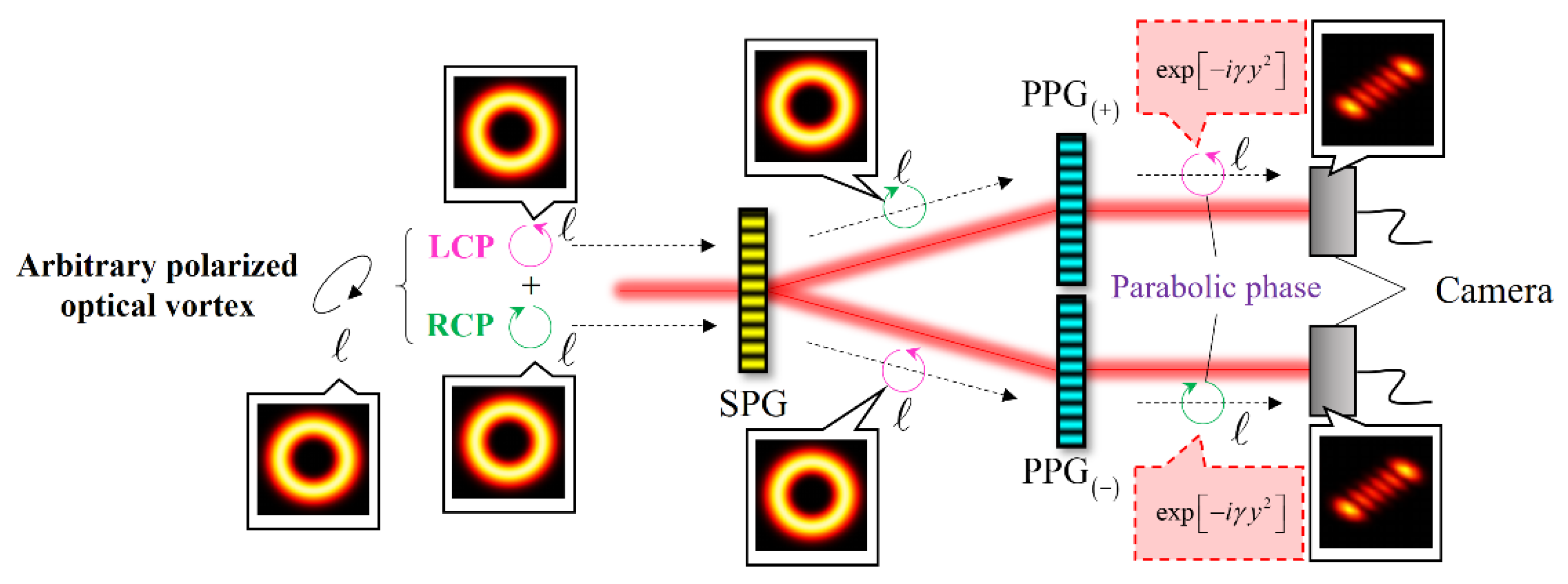
Figure 1. Schematic of the OV characterizer assembled with SPG and two PPGs.
Applsci 12 08768 g001
Figure 2. Structure (left) and function (right) of (a) SPG, (b) PPG(+), and (c) PPG(−).
Applsci 12 08768 g002
Figure 3. Optical setup for fabricating SPG and PPGs from PPLC by photoalignment.
Applsci 12 08768 g003
Figure 4. Schematic showing the optical setup for the demonstration of (a) OV and (b) PV characterizations using one SPG and two PPGs.
Applsci 12 08768 g004
Figure 5. Numerically simulated and experimentally observed beam profiles obtained at the two detection positions of the mode characterizer for an incident OV with = 4 .
Applsci 12 08768 g005
Figure 6. Numerically simulated and experimentally observed beam profiles at the two detection positions of the mode characterizer for an incident PV with (a) p = 1 and (b) p = 2 .
Applsci 12 08768 g006
Publisher’s Note: MDPI stays neutral with regard to jurisdictional claims in published maps and institutional affiliations.