Abstract
The mesogen orientations of liquid crystals are sensitive to the nature of the contacting surface. For side chain liquid crystalline polymer (SCLCP) films, most investigations have been conducted for thin films formed on a solid substrate surface such as glass, quartz and metal oxides, and little knowledge has been accumulated for SCLCP films whose top surface is covered by amorphous polymers. This work presents the effect of a topcoat with amorphous polymers placed on SCLCP films on the mesogen orientation and photoalignment behavior. When an SCLCP film that adopts a homeotropic mesogen orientation is covered with a glass plate or polymer layer, the mesogens turns to a random planar orientation. This planar orientation is favorable for efficient in-plane photoalignment by irradiation with linear polarized light. An in-plane order parameter exceeding 0.5 is readily obtained. Unexpectedly, a significant stabilization of the liquid crystal phase by over 10 °C is observed above the isotropization temperature of the SCLCP. These fundamental sets of knowledge should be significant in the fabrication of various polymer LC devices.
1. Introduction
The orientation of liquid crystals (LCs) is highly sensitive to the nature of the substrate surface. This property is particularly significant for the fabrication of LC display panels and other optical devices. Recently, photoalignment technology has become important as an alternative to the rubbing process in LC display panel production. Photoreactive polymer layers that respond to linear polarized light or diagonal irradiation light are usually used in these processes [1,2,3,4,5,6,7,8,9]. As related systems, photoalignable side chain liquid crystal polymers (SCLCPs) have been widely studied in the fabrication of optically functional devices [10,11,12,13] and light-driven mechanical elastomer films [14,15,16,17,18].
SCLCP films are mostly prepared by the spin-coating procedure. In spin-coated films, one side of the film is supported by the solid substrate surface, and the other side contacts the air (free surface). It has recently become evident that the free surface plays an essential role in the mesogen orientation on SCLCP films [6,7,8,9,19,20,21,22,23,24,25,26,27]. The existence of a top layer on SCLCP films strongly influences the mesogen orientation. Such an effect has occasionally been discussed in block copolymers possessing an SCLCP block to control the orientation of the microphase separation (MPS) structure [19,20,21]. Fukuhara et al. [19] showed that a vertically aligned MPS structure turns into a planar one when a surface segregated layer exists on the top surface. Komura et al. [20] showed that a homeotropic LC and cylindrical MPS structure is changed to a planar one when the film is covered with silicone oil. Xie et al. [21] indicated the orientation control of a cylindrical MPS structure by converging the top surface with a water-soluble polymer. Other than SCLCPs, coverage of the free surface of amorphous block copolymers such as poly(styrene-block-trimethylsilylstyrene-block-styrene) was conducted by Bate et al. [28]. They adopted a polarity-transformable topcoat to attain the vertical orientation of the MPS, which is essential in the block copolymer lithography.
For simple SCLCP systems without an MPS structure, Fukuhara et al. [23] demonstrated that the homeotropic orientation of a light-passive SCLCP film is altered to a planar one when the top surface is covered with an azobenzene (Az)-containing polymer via annealing-assisted surface segregation or inkjet printing. This system provides a photopatterning of the birefringent character of the whole film, indicating that the top photoalignable layer can command the whole light-passive SCLCP film existing underneath. Shortly after this approach, Nakai et al. [24] demonstrated that the mesogen orientation of a light-passive SCLCP film can be switched repeatedly by alternative light irradiation to a surface-segregated Az SCLCP existing on the surface. This system can be compared with the original photo-switchable alignment system achieved by an azobenzene monolayer on a solid substrate called the “command surface” [1,29,30]. Kawatsuki et al. [25,26,27] proposed a smart strategy to use low molecular mass molecules to modify the top surface. By deposition of an aromatic amine onto a benzaldehyde-containing side chain polymer film, the side chain reacts with the aromatic amine to form photoalignable N-benzylideneaniline. After photoalignment is attained, the top layer can be removed by heat-assisted sublimation. Therefore, the photoalignment ability can be switched or fixed on demand.
Rod-like mesogens tend to be anchored to the solid surface and free surface horizontally (planarly) [31,32,33] and vertically (homeotropically) [34,35,36,37,38] in relation to the interface plane, respectively, due to the excluded volume effect. The orientation alternations for SCLCPs, as mentioned above, can be understood in line with these theoretical and experimental facts. An Az-containing SCLCP, shown in Scheme 1 (PAz), shows a homeotropic orientation as well [19], but interestingly, we have found that a cyanobiphenyl (CB) SCLCP with a polymethacrylate main chain exceptionally adopts a random planar orientation [22]. When the Az and CB mesogens are randomly copolymerized [39,40], the homeotropic or planar mesogen orientation is changed, depending on the copolymerization ratio [39].
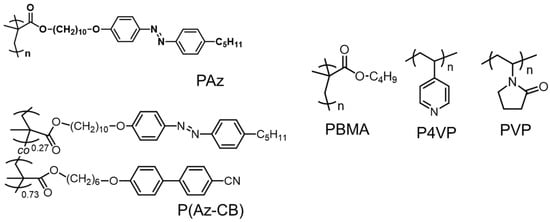
Scheme 1.
Chemical structures of polymers used in this study.
Despite the accumulation of the above explorations, a systematic study on the effect of a topcoat with amorphous polymers on SCLCP films has not been conducted yet. In this context, we have conducted an investigation using various conventional amorphous polymers with different glass transition temperatures (Tg) and poly(butyl methacrylate) (PBMA, Tg = ca. 20 °C), poly(4-vinyl pyridine) (P4VP, Tg = 140 °C) and poly(vinyl pyroridone) (PVP, Tg = 150 °C) as the topcoat material. These polymers were chosen for the feasibility of an additional topcoat using poor solvents for the underlying SCLCPs. In this study, most experiments were conducted with PAz, but in the examinations of in-plane photoalignment, a random copolymer of P(Az-CB) (Az:CB = 0.27:0.73) was further examined (see Scheme 1). This copolymerization ratio was chosen because this copolymer adopts a random planar orientation that is favorable for the in-plane photoalignment [39]. In this study, we have also found a significant stabilization effect of the LC phase by top-coating with an amorphous polymer.
2. Materials and Methods
2.1. Materials
Solvents, chloroform (spectroscopic grade), cyclohexane (spectroscopic grade), acetone and methanol were purchased from Kanto Chemical Co., Ltd. (Tokyo, Japan) and Kishida Chemical Co., Ltd. (Osaka, Japan) and used without purification.
PAz, P(Az-CB), PBMA, P4VP and PVP were synthesized previously in our laboratory [19,40]. PVP was obtained from Nacalai Tesque Inc. (Kyoto, Japan).
The molecular mass data (number-averaged molecular mass (Mn) and polydispersity index (Mw/Mn)) are summarized in Table 1.

Table 1.
Molecular mass data of the polymers.
2.2. Sample Preparation
The SCLCPs were spin-coated from chloroform at 1 or 4 weight % on a quartz plate washed and wiped with acetone. The films were annealed at 120 °C for 10 min. The top-coating of the amorphous polymers was also performed by spin-coating using poor solvents for the SCLCPs. The PBMA, P4VP and PVP (2 weight %) on the SCLCP films were top-coated with solvents of cyclohexane or methanol. These top-coated laminated films were also annealed at 120 °C for 10 min.
The SCLCP samples were sandwiched between glass substrates with an originally designed LC cell. The glass plate of one side was 1.5 mm so that the X-ray could properly penetrate from the in-plane direction through the two glass plates. The cell gap was adjusted with 8-μm capton films (Toray-Du Pont) and fixed with a UV-curing resign (Norland 65) and an epoxy resin (Araldite Rapid, Nichiban). The SCLCP was incorporated into the gap by capillary force at 120 °C between two glass substrates. The extra amount of the polymer was wiped off with chloroform.
2.3. Measurements
Small-angle X-ray scattering (SAXS) measurements were performed with an FR-E (Rigaku Corp.) equipped with a 2D imaging plate (R-AXIS IV, Rigaku Corp, Tokyo, Japan). The X-ray source and camera length were a Cu Kα beam (0.154 nm) and 300 mm, respectively. Grazing incident angle SAXS (GI-SAXS) measurements were also achieved with this instrument. Precise tilt control for this measurement was achieved with an ATS-C316-EM (Chuo Precision Industrial Co., Ltd., Tokyo, Japan).
Gel permeation chromatography measurements were achieved with a DS-4 Shodex system equipped with KF-803L, KF-804L and KF-805 columns. The detection was achieved with a UV absorption (UV-41, Shodex) or a reflective index detector (RI-101, Shodex).
The thermal transition properties of the polymers were evaluated by differential scanning calorimetry (DSC) using a TA 200 (TA Instruments).
The UV-visible absorption spectra were found with an Agilent 8453 spectrometer (Agilent Technologies) with a light source of a deuterium/tungsten lamp.
Contact angle measurements were made with a CA-XP (Kyowa Interface Science Co., Ltd., Niiza, Japan). Water droplets of 3 μL were placed onto the polymer films at room temperature. The measurements were made after 5 s of dropping.
The topographical surface profiles for the evaluation of the film thickness were obtained with white light interference microscopy using a BE-S501 (Nikon Corp, Tokyo, Japan).
Polarized optical microscopic observations were performed with a BX-51 (Olympus Corp, Tokyo, Japan).
2.4. Photoirradiation
Photoirradiation was performed using a mercury lamp (Sanei Electric Supercure-203). To select the 436-nm line, a combination of optical filters (Toshiba glass V-44 and V-43) was used. The light intensity was measured with a TQ8210 (ADC Corporation).
3. Results and Discussion
3.1. Mesogen Orientation of PAz Films
First, the mesogen orientations of the SCLCP films were evaluated without a topcoat (contacting with air), in a sandwiched cell between glass plates and then with films with polymer top-coated systems.
3.1.1. PAz Film Contacting with Air
Figure 1 displays the GI-SAXS data for PAz films with a 100-nm (a) and 400-nm (b) thickness on a glass substrate at room temperature. These thicknesses were chosen because the former should have significant influence from the constraint effects from the solid surface, and the latter could be mostly free from such constraints. In general, the surface constraint effect reached the level of some tens of nanometers [41]. The sample was annealed at 120 °C (isotropic phase) for 10 min and then subjected to measurements. The scattering data were essentially the same for the two thickness films. The scattering spots were observed in the out-of-plane direction at 2θ = ca. 3.2° (spacing: d = 2.8–2.9 nm) and 2θ = ca. 6.4° (d = 1.4 nm), corresponding to (001) and (002) scattering, respectively. These data indicate a lamella structure formation oriented horizontally with the substrate. The film with 400 nm gave the clearer scattering signals because more intense X-ray signals were obtained. In this grazing angle measurement configuration, the small deviation in the d value (0.1 nm) between the two samples was within the experimental error. The d spacing of 2.8–2.9 nm shows that a smectic C phase with a tilted molecular orientation with the lamella plane was formed [19]. Some disordering was involved in the film of a 400-nm thickness, as can be seen from the azimuthal arc scattering. This seems to reflect that more orientational freedom was allowed, because the constraint from the surface was lessened.
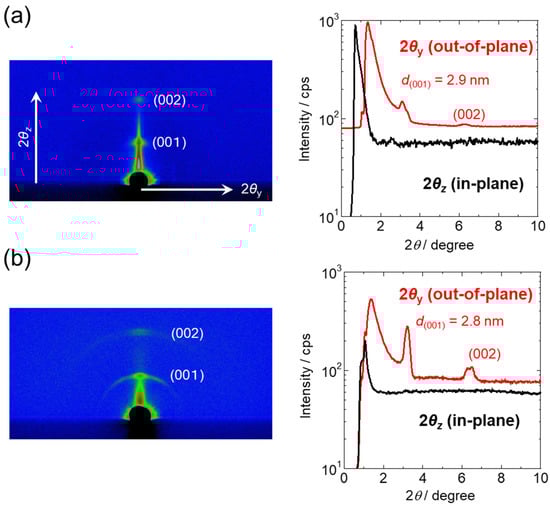
Figure 1.
GI-SAXS data of PAz films with thicknesses of 100 nm (a) and 400 nm (b). In each part, left and right figures display 2D GI-SAXS patterns and 1D intensity profiles taken from the 2D data, respectively. In the left profiles, red and black data show the out-of-plane and in-plane directions, respectively.
3.1.2. PAz Film Sandwiched between Two Glass Substrates
The PAz film was sandwiched between two glass substrates as described in Section 2.2. Figure 2 shows the 2D GI-SAXS and 1D profiles of this sample at room temperature (a) and at 90 °C (b). In contrast to the results for the film contacting with air (Section 3.1.1), the lamellar structure was more randomly oriented and rather preferentially in the in-plane direction. At room temperature, another spot at 55° from the normal was also observed for the (001) scattering. These facts indicate that the lamellar plane was preferentially oriented vertically with a tilted structure, reflecting the smectic C phase (d = 2.7 nm). At 90 °C, on the other hand, the scattering tilt structure disappeared, and scatterings showing a periodicity at d = 3.4 nm were observed both in the in-plane and out-of-plane directions. This shows that the LC structure was changed to a smectic A phase at the higher temperature. In this way, the free (air) surface and the solid substrate gave the homeotropic and planar anchoring for the Az mesogens, respectively, which is consistent with the theoretical considerations based on the excluded volume effect [31,32,34].
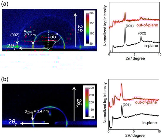
Figure 2.
GI-SAXS data of PAz film sandwiched between two glass substrates at room temperature (a) and at 90 °C (b). In each part, left and right figures display 2D GI-SAXS patterns and 1D intensity profiles taken from the 2D data, respectively. In the left profiles, red and black data show the out-of-plane and in-plane directions, respectively.
3.1.3. PAz Film with Top-Coated Amorphous Polymers
Next, the surfaces of the PAz films (thickness: 100 nm) were covered with PBMA, P4VP and PVP. PBMA was overlaid using cyclohexane and P4VP and PVP with methanol, both of which are poor solvents for PAz. The thickness of the overlaid amorphous polymers was 100–200 nm. The coverage of the top surface of the PAz with the amorphous polymers was confirmed by static contact angle measurements using a water droplet. Table 2 lists the contact angles of the water droplets (θw) on various polymer surfaces. θw values from the literature are also shown in parentheses for comparison. The surface of the PAz was highly hydrophobic due to the homeotropic anchoring, where the alkyl tail was oriented toward the air. When the top surface was covered with the amorphous polymers, the resulting θw agreed well with the pure amorphous polymers, indicating that the top-coating was successfully performed.
Table 2.
Static contact angles of water droplets at room temperature.
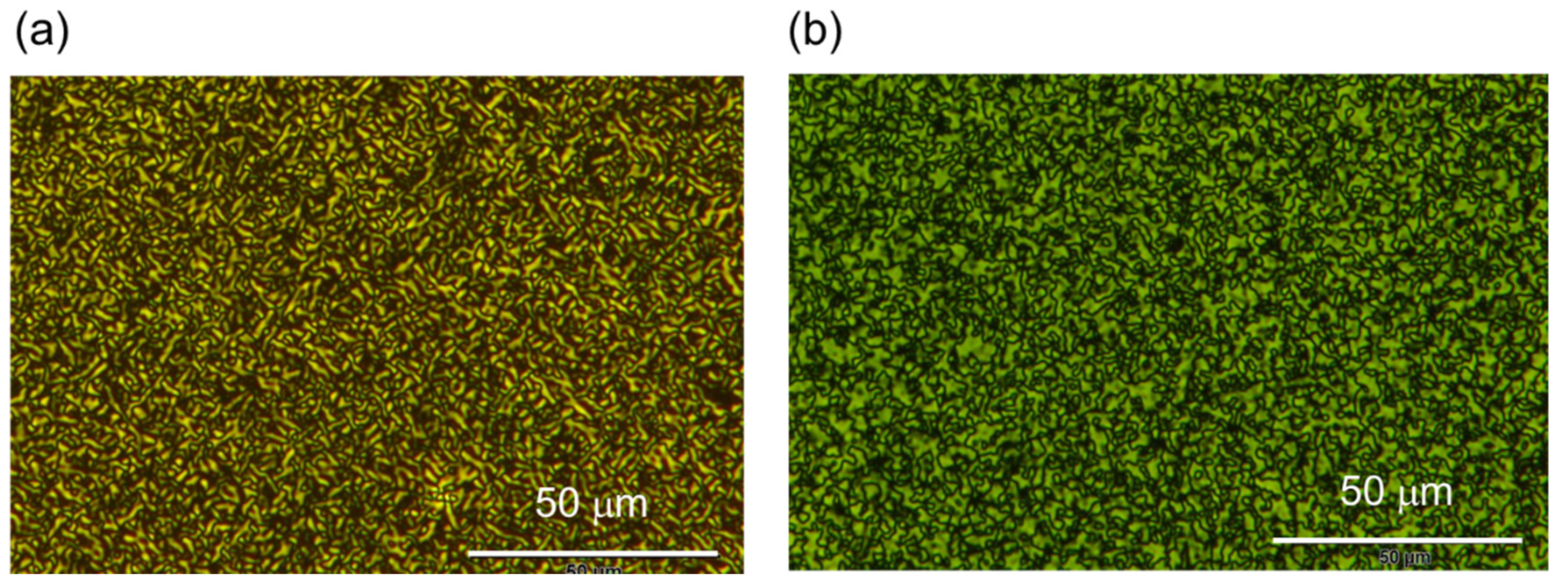
The PAz films covered with PBMA, P4VP and PVP at room temperature consistently provided the same results as those for the glass substrate (see Section 3.1.2). The films covered with amorphous polymers indicated a random planar orientation state, whose typical domain size range was approximately some micrometers. Representative examples of the POM image are shown in Figure 3 for the PAz films covered with PBMA films 100 nm (a) and 400 nm (b) thick.
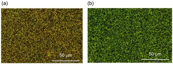
Figure 3.
POM images of PAz of 100-nm thickness covered with PBMA films 100 nm (a) and 400 nm (b) thick.
Figure 4 shows the GI-SAXS data for the PAz film covered with PVP as an example. By covering the surface with the polymer film, the scattering spots became sharpened, indicating that the orientational disorder became more suppressed (compared with the data in Figure 2). A thicker topcoat film with a 400-nm thickness was also examined. The thickness of the topcoat layer did not significantly influence the results.
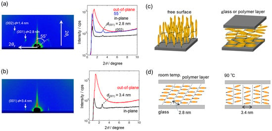
Figure 4.
GI-SAXS data for PAz film (thickness: 100 nm) covered with PVP (thickness: 100 nm) at room temperature (a) and 90 °C (b). In each part, left and right figures display 2D GI-SAXS patterns and 1D intensity profiles taken from the 2D data, respectively. In the left profiles, red, black and blue lines show the out-of-plane and in-plane directions and 55° to the normal direction, respectively. (c) Schematics on the mesogen orientation induced by the free surface (left) and glass plate or polymer coat on the top (right) are displayed. (d) Schematic illustrations of the structure and orientation of the smectic C phase at room temperature (left) and vertically oriented smectic A phase at 90 °C (right) of PAz film covered with a polymer layer.
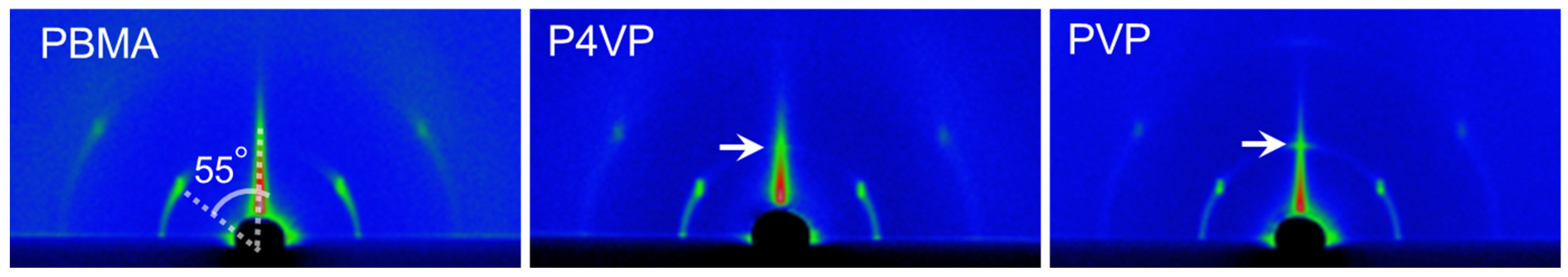
The three polymer layers (PBMA, P4VP and PVP) on the top essentially gave the same anchoring effect, but small differences were observed when the PAz film was thickened to 400 nm. Figure 5 indicates the 2D GI-SAXS images of the PAz film covered with the three polymer layers. At room temperature, the X-ray images consistently gave the tilt layer structure ascribed to the smectic C phase, but the smectic layer with the PBMA topcoat indicated a more disordered orientation state, judging from the vague arc-scattering image (left) compared with the other two polymer topcoats. In the cases of P4VP and PVP topcoats (middle and right), layer spacing was also observed in the out-of-plane direction (white arrow). This seems to show that P4VP and PVP tend to induce homeotropically aligned mesogens partially in the contacting region with the polymer. We do not have clear explanations for the different characteristics between the PBMA and P4VP or PVP at present. One plausible possibility is that the difference in Tg can affect the anchoring behavior [44]. As the polarity of the polymers also differed, this was not the decisive factor to account for the present observations.
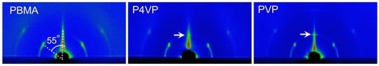
Figure 5.
2D GI-SAXS data for thicker PAz films (thickness: 400 nm) covered with PBMA (left), P4VP (middle) and PVP (right) layer on top at room temperature. For the white arrow, see the text.
3.1.4. Reversible Orientation Switching by Coating and Removal of the Top Layer
As displayed in Figure 4c, the homotropic or planar alignment is changed by the absence and presence of polymer topcoat. Here, an attempt was made to confirm the reversibility of the mesogen by repeated coating and removal of the polymer. To evaluate the Az mesogen orientation, UV-visible absorption spectra of the films on a quartz plate were taken in the transmission mode. The ππ* band of Az around 320–350 nm region reflects the orientation of the long axis of Az mesogen.
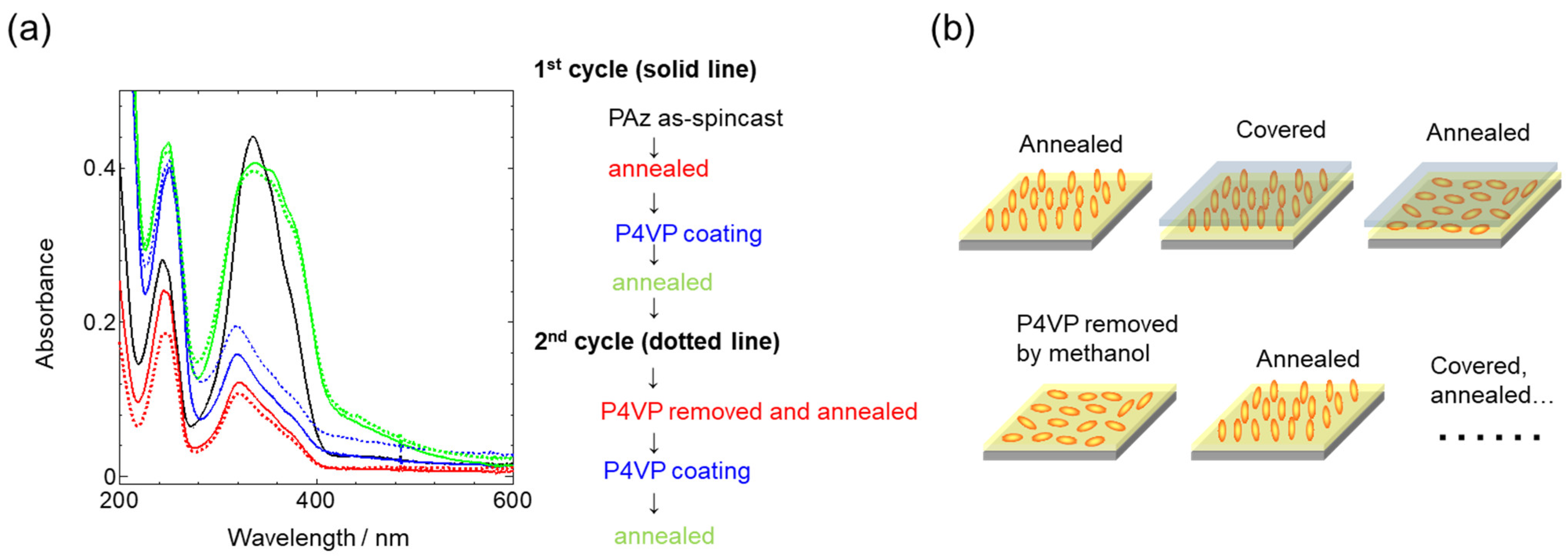
Figure 6 shows the changes in the UV-visible absorption spectrum in the course of the coating and removal procedures of the P4VP top layer. A spin-coated PAz film (thickness: 100 nm) was first annealed (120 °C for 10 min), and then the absorbance of the ππ* band was significantly reduced with a slight blue shift (black solid line to the red solid line). After annealing, the spectrum was somewhat broadened, probably due to the involvement of a J-type aggregate [45]. This shows the orientational change of Az to a more vertical orientation state. When an overcoat of P4VP using methanol followed by annealing was achieved, the ππ* band almost recovered to the spin-coated state with spectrum broadening (green solid line). Next, the topcoat film of P4VP was washed (removed) with methanol and annealed. The Az mesogen became vertically aligned again (red dotted line). By coating with P4VP followed by annealing, the ππ* band recovered (green dotted line). In this manner, the homeotropic and planar alignments of Az mesogen can be successfully altered repeatedly by topcoat manipulation. The orientation changes of the mesogens during such processes are schematically displayed in Figure 6b.
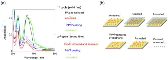
Figure 6.
(a) UV-visible absorption spectra of PAz film (thickness: 100 nm) in repeated cycles of top-coating and removal of P4VP with annealing. The processes are indicated in colors on the right side, and the colored spectra on the left side correspond to the colored steps. (b) Schematic illustration of the mesogen orientation by repeated cycles of coverage and removal of the P4VP top layer.
3.2. Photoalignment of PAz and P(Az-CB) Films
The homeotropic orientation of Az mesogens was unfavorable for the in-plane alignment because the transition moment of Az absorption was almost parallel to the long axis of the chromophore. For the efficient light absorption, the long axis of the Az should be oriented horizontally with the substrate. This desired Az orientation for photoalignment can be realized for high-density surface-tethered polymer brushes of SCLCP [46,47,48]. In the present work, the horizontal orientation was attained by coating with a polymer layer (Section 3.1.3), and the in-plane photoalignment was examined by irradiation with LPL.
3.2.1. In-Plane Photoalignment of PAz Coated with Polymer Layers
A PAz polymer (thickness: 100 nm) was prepared, and then the top surface was coated with a polymer layer of PMBA and PVP as described in Section 2.2. The laminate film was first annealed at 120 °C for 10 min. After cooling the film to room temperature, the sample was heated to 90 °C, and the LPL at 436 nm was irradiated at 1.0 mW cm−2. During these processes, the Az mesogens kept the planar orientation, as confirmed by UV-visible absorption spectroscopy.
Figure 7 shows the polarized UV-visible absorption spectra of the resulting films coated with PBMA and PVP. In both cases, a strong dichroic characteristic appeared, as indicated in Figure 6a,b. The order parameter (S) was calculated with the following equation
and reached 0.67 and 0.77 for the PBMA and PVP, respectively. Figure 7c,d displays the GI-SAXS data for the PBMA-coated PAz film. Here, the incidence for the X-ray beam was selected parallel (//) and perpendicular () to the irradiated LPL, as illustrated below in Figure 7d. The X-ray scattering spot (d = 3.5 nm) was observed only in the in-plane direction of the parallel X-ray incidence (Figure 7c). Essentially, no scattering signal was obtained for the perpendicular incidence (Figure 7d). These facts show that highly homogeneous in-plane structural anisotropy was attained, which coincided with the polarized spectral data.
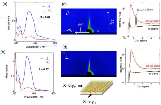
Figure 7.
Polarized UV-visible absorption spectra of PAz film (thickness: 100 nm) coated with PBMA (a) and PVP (b). Blue and red lines indicate spectra taken perpendicular () and parallel (//) to the direction of exposed LPL In (c) and (d), GI-SAXS data are shown for the photoaligned PAz coated with a PBMA layer.
3.2.2. In-Plane Photoalignment of P(Az-CB)
It should be interesting to grasp the effect of a coated polymer layer on the photoalignment behavior. However, the Az mesogen of the PAz oriented vertically and horizontally after annealing with and without the polymer coat, respectively, and it was impossible to make direct comparisons. Therefore, in this section, the photoalignment process is compared using P(Az-CB) that adopts a planar orientation without the topcoat [22,39]. As mentioned in the introductory remark, the copolymerization ration of Az:CB = 0.27:0.73 gives a random planar orientation. In fact, the absorption spectra of P(Az-CB) before and after annealing hardly results in any changes, indicating that this copolymer provides a random planar orientation without a polymer topcoat.
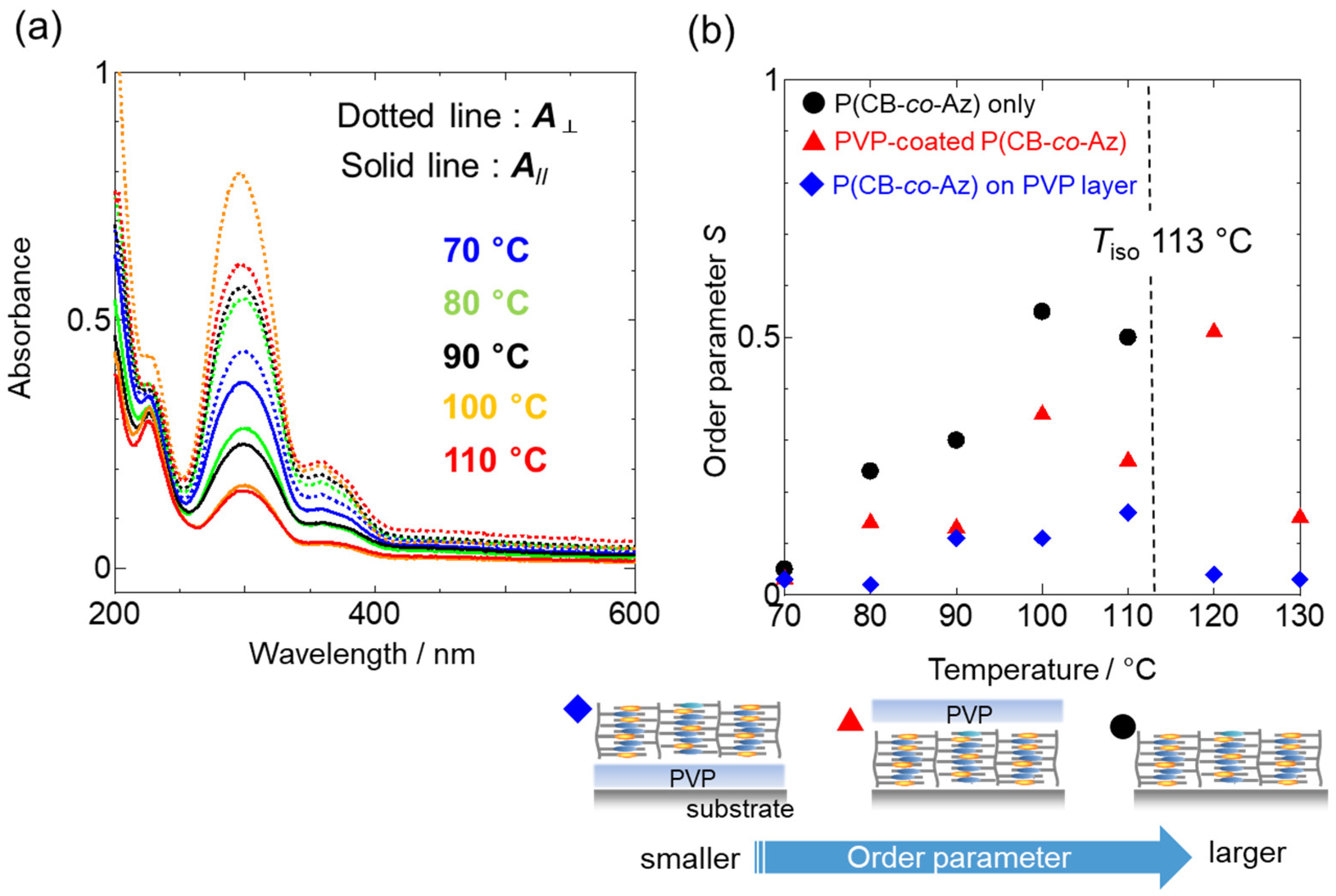
LPL irradiation was conducted at 70–130 °C. Figure 8a shows the polarized UV-visible absorption spectra for P(Az-CB) without a topcoat irradiated at various temperatures. Spectrum measurements were performed after cooling to room temperature. The ππ* bands of Az and CB were positioned around 360 and 290 nm, respectively. These spectra were obtained after LPL irradiation at a dose of 1.0 J cm−2. The increase in S was saturated at 200 mJ cm−2, and further irradiation did not affect the degree of in-plane optical anisotropy. The dotted and solid lines correspond to the polarized spectra in the perpendicular and parallel directions of the LPL, respectively. In all spectra, the dichroic ratios (/A//) obtained for the Az and CB ππ* bands coincided with each other under all conditions, showing that the two mesogens were photoaligned in a highly cooperative manner.

Figure 8.
(a) Polarized UV-visible absorption spectra of P(Az-CB) film (thickness: 100 nm) without topcoat after LPL irradiation at various temperatures. Dotted and solid lines correspond to spectra taken perpendicular and parallel with irradiated LPL. (b) In-plane order parameter of P(Az-CB) films. Black, red and blue symbols correspond to data for pure P(Az-CB) film, P(Az-CB) film coated with PVP layer, and P(Az-CB) film formed on PVP underlayer, respectively. A scheme below b indicates the relationship between the film constitution and resulting in-plane S.
In Figure 8b, the order parameter after the above LPL irradiation conditions was plotted as a function of the temperature for a P(Az-CB) film without a topcoat (black circle) on a quartz plate, a PVP-coated P(Az-CB) film (red triangle) and a P(Az-CB) film prepared on a PVP-coated substrate (blue diamond). The last film constitution was examined to grasp the influence on the underlying substrate surface. In these evaluations, the photoalignment procedure was achieved at each target temperature and then cooled down to room temperature for spectral measurements. The in-plane S increases with the increase in temperature until reaching the isotropization temperature (Tiso) of 113 °C. The extent of S enhancement is strongly dependent on the film constitution. Among the three types of films, the pure P(Az-CB) film provided the highest in-plane S at all temperatures, with S exceeding 0.5 above 100 °C. However, this film exhibited film damage (dewetting) above 113 °C (indicated by Tiso in Figure 8b), and the evaluation of S above this temperature was not feasible. Interestingly, when the P(Az-CB) film was formed on a polymer layer of PVP, the film was stable enough to evaluate S up to 130 °C. The dewetting seemed to be suppressed by the stronger molecular interactions of P(Az-CB) with the PVP by dipole-dipole interactions. However, S was significantly reduced in this case (S = 0.15 at 110 °C), seemingly due to this strong anchoring that could restrict from the molecular reorientation by LPL. Intermediate S values were obtained for the P(Az-CB) films coated with PVP. More importantly and unexpectedly, the LC state was maintained above 113 °C, the S value reached the maximum level above Tiso (S = 0.52 at 120 °C), and the photoalignment was possible even at 130 °C (S = 0.15). Actually, the GI-SAXS measurement confirmed the smectic A phase at 120 °C. These facts suggest the strong influence of the free surface side for alignment control in SCLCP films which, on the other hand, was not observed when the same PVP layer was placed on the solid substrate side (compare the red and blue symbols at 120 °C in Figure 8b).
4. Conclusions
The use of rubbed or photoirradiated polymer films has frequently been achieved to align LC materials. However, the alignment behavior of SCLCP films capped with amorphous polymers has hardly been investigated. This work was undertaken to shed light on the orientation and photoalignment behavior of such systems. This systematic approach demonstrated the significant effect of polymer coverage on SCLCPs. We believe that the results obtained here should be of great help for the fabrication and understanding of various types of polymer-based SCLCP devices. Polymer substrates are important for the construction of flexible LC devices. The significant thermal stabilization of the LC phase by covering with a polymer layer, as mentioned in the last section, seems to provide a new outlook and expand the choice of SCLCPs for utilization toward various devices.
Author Contributions
Conceptualization, S.N. and T.S.; experiments and analysis, M.F. and M.H.; writing and editing, T.S. and S.N. All authors have read and agreed to the published version of the manuscript.
Funding
This research was funded by the JSPS KAKENHI, grant numbers 19H02774 to S.N. and 21H01983 and 21K19000 to T.S., and JST CREST grant number JPMJCR21B5 to S.N. S.N. would also like to thank Admatechs Co., Ltd. for their financial support.
Conflicts of Interest
The authors declare no conflict of interest.
References
- Ichimura, K. Photoalignment of Liquid-Crystal Systems. Chem. Rev. 2000, 100, 1847–1873. [Google Scholar] [CrossRef] [PubMed]
- Chigrinov, V.G.; Kozenkov, V.M.; Kwok, H.-S. Photoalignment of Liquid Crystalline Materials; John Wiley & Sons: West Sussex, UK, 2008. [Google Scholar]
- Kawatsuki, N. Photoalignment and Photoinduced Molecular Reorientation of Photosensitive Materials. Chem. Lett. 2011, 40, 548–554. [Google Scholar] [CrossRef]
- Yaroshchuk, O.; Reznikov, Y. Photoalignment of liquid crystals: Basics and current trends. J. Mater. Chem. 2012, 22, 286–300. [Google Scholar] [CrossRef]
- Seki, T.; Nagano, S.; Hara, M. Versatility of photoalignment techniques: From nematics to a wide range of functional materials. Polymer 2013, 54, 6053–6072. [Google Scholar] [CrossRef]
- Seki, T. New strategies and implications for the photoalignment of liquid crystalline polymers. Polym. J. 2014, 46, 751–768. [Google Scholar] [CrossRef]
- Nagano, S. Inducing Planar Orientation in Side-Chain Liquid-Crystalline Polymer Systems via Interfacial Control. Chem. Rec. 2016, 16, 378–392. [Google Scholar] [CrossRef] [PubMed]
- Seki, T. A Wide Array of Photoinduced Motions in Molecular and Macromolecular Assemblies at Interfaces. Bull. Chem. Soc. Jpn. 2018, 41, 1026–1057. [Google Scholar] [CrossRef]
- Nagano, S. Random Planar Orientation in Liquid-Crystalline Block Copolymers with Azobenzene Side Chains by Surface Segregation. Langmuir 2019, 35, 5673–5683. [Google Scholar] [CrossRef]
- Shibaev, V.; Bobrovsky, A.; Boiko, N. Photoactive liquid crystalline polymer systems with light-controllable structure and optical properties. Prog. Polym. Sci. 2003, 28, 729–836. [Google Scholar] [CrossRef]
- Zhao, Y.; Ikeda, T. Smart Light-Responsive Materials; John Wiley & Sons: Hoboken, NJ, USA, 2009. [Google Scholar]
- Ikeda, T. Photomodulation of liquid crystal orientations for photonic applications. J. Mater. Chem. 2003, 13, 2037–2057. [Google Scholar] [CrossRef]
- Priimagi, A.; Shevchenko, A. Azopolymer-based micro- and nanopatterning for photonic applications. J. Polym. Sci. Part B Polym. Phys. 2014, 52, 163–182. [Google Scholar] [CrossRef]
- Yu, Y.; Nakano, M.; Ikeda, T. Directed bending of a polymer film by light. Nature 2003, 425, 145. [Google Scholar] [CrossRef] [PubMed]
- Ube, T.; Ikeda, T. Photomobile Polymer Materials with Crosslinked Liquid-Crystalline Structures: Molecular Design, Fabrication, and Functions. Angew. Chem. Int. Ed. 2014, 53, 10290–10299. [Google Scholar] [CrossRef]
- Yu, H. Photoresponsive liquid crystalline block copolymers: From photonics to nanotechnology. Prog. Polym. Sci. 2014, 39, 781–815. [Google Scholar] [CrossRef]
- Lv, J.; Liu, Y.; Wei, J.; Chen, E.; Qin, L.; Yu, Y. Photocontrol of fluid slugs in liquid crystal polymer microactuators. Nature 2016, 537, 179–184. [Google Scholar] [CrossRef]
- Priimagi, A.; Barrett, C.J.; Shishido, A. Recent twists in photoactuation and photoalignment control. J. Mater. Chem. C 2014, 35, 7155–7162. [Google Scholar] [CrossRef]
- Fukuhara, K.; Fujii, Y.; Nagashima, Y.; Hara, M.; Nagano, S.; Seki, T. Liquid-Crystalline Polymer and Block Copolymer Domain Alignment Controlled by Free-Surface Segregation. Angew. Chem. Int. Ed. 2013, 52, 5988–5991. [Google Scholar] [CrossRef]
- Komura, M.; Yoshitake, A.; Komiyama, H.; Iyoda, T. Control of Air-Interface-Induced Perpendicular Nanocylinder Orientation in Liquid Crystal Block Copolymer Films by a Surface-Covering Method. Macromolecules 2015, 48, 672–678. [Google Scholar] [CrossRef]
- Xie, H.-L.; Li, X.; Suh, H.S.; Ren, J.-X.; Craig, G.S.W.; Arges, C.G.; Nealey, P.F. Water-soluble top coats for orientation control of liquid crystal-containing block copolymer films. J. Polym. Sci. Part B Polym. Phys. 2017, 55, 1569–1574. [Google Scholar] [CrossRef]
- Tanaka, D.; Nagashima, Y.; Hara, M.; Nagano, S.; Seki, T. Alternation of Side-Chain Mesogen Orientation Caused by the Backbone Structure in Liquid-Crystalline Polymer Thin Films. Langmuir 2015, 31, 11379–11383. [Google Scholar] [CrossRef]
- Fukuhara, K.; Hara, M.; Nagano, S.; Seki, T. Free-surface molecular command systems for photoalignment of liquid crystalline materials. Nat. Commun. 2014, 5, 3320. [Google Scholar] [CrossRef] [PubMed]
- Nakai, T.; Tanaka, D.; Hara, M.; Nagano, S.; Seki, T. Free Surface Command Layer for Photoswitchable Out-of-Plane Alignment Control in Liquid Crystalline Polymer Films. Langmuir 2016, 32, 909–914. [Google Scholar] [PubMed]
- Kawatsuki, N.; Miyake, K.; Kondo, M. Facile Fabrication, Photoinduced Orientation, and Birefringent Pattern Control of Photoalignable Films Comprised of N-Benzylideneaniline Side Groups. ACS Macro Lett. 2015, 4, 764–768. [Google Scholar] [CrossRef]
- Kawatsuki, N.; Inada, S.; Fujii, R.; Kondo, M. Photoinduced Birefringent Pattern and Photoinactivation of Liquid-Crystalline Copolymer Films with Benzoic Acid and Phenylaldehyde Side Groups. Langmuir 2018, 34, 2089–2095. [Google Scholar] [CrossRef] [PubMed]
- Ito, A.; Norisada, Y.; Inada, S.; Kondo, M.; Sasaki, T.; Sakamoto, M.; Ono, H.; Kawatsuki, N. Photoinduced Reorientation and Photofunctional Control of Liquid Crystalline Copolymers with in Situ-Formed N-Benzylideneaniline Derivative Side Groups. Langmuir 2021, 37, 1164–1172. [Google Scholar] [CrossRef]
- Bates, C.M.; Seshimo, T.; Maher, M.J.; Durand, W.J.; Cushen, J.D.; Dean, L.M.; Blachut, G.; Ellison, C.J.; Willson, C.G. Polarity-Switching Top Coats Enable Orientation of Sub–10-nm Block Copolymer Domains. Science 2012, 338, 775–779. [Google Scholar] [CrossRef]
- Ichimura, K.; Suzuki, Y.; Seki, T.; Hosoki, A.; Aoki, K. Reversible change in alignment mode of nematic liquid crystals regulated photochemically by command surfaces modified with an azobenzene monolayer. Langmuir 1988, 4, 1214–1216. [Google Scholar] [CrossRef]
- Seki, T.; Sakuragi, M.; Kawanishi, Y.; Suzuki, Y.; Tamaki, T.; Fukuda, R.; Ichimura, K. “Command surfaces” of Langmuir-Blodgett films. Photoregulations of liquid crystal alignment by molecularly tailored surface azobenzene layers. Langmuir 1993, 9, 211–218. [Google Scholar]
- Okano, K. Anisotropic Excluded Volume Effect and Alignment of Nematic Liquid Crystal in a Sandwich Cell. Jpn. J. Appl. Phys. 1983, 22, L343–L344. [Google Scholar] [CrossRef]
- Berreman, D.W. Solid Surface Shape and the Alignment of an Adjacent Nematic Liquid Crystal. Phys. Rev. Lett. 1972, 28, 1683–1686. [Google Scholar] [CrossRef]
- Tanaka, D.; Mizuno, T.; Hara, M.; Nagano, S.; Saito, I.; Yamamoto, K.; Seki, T. Evaluations of Mesogen Orientation in Thin Films of Polyacrylate with Cyanobiphenyl Side Chain. Langmuir 2016, 32, 3737–3745. [Google Scholar] [CrossRef] [PubMed]
- Scaramuzza, N.; Berlic, C.; Barna, E.S.; Strangi, G.; Barna, V.; Ionescu, A.T. Molecular Simulation of the Free Surface Order in NLC Samples. J. Phys. Chem. B 2004, 108, 3207–3210. [Google Scholar] [CrossRef]
- Chen, S.M.; Hsieh, T.C.; Pan, R.P. Magnetic-field-induced Fréedericksz transition and the dynamic response of nematic liquid-crystal films with a free surface. Phys. Rev. A 1991, 43, 2848–2857. [Google Scholar] [CrossRef]
- Canabarro, A.A.; de Oliveira, I.N.; Lyra, M.L. Homeotropic surface anchoring and the layer-thinning transition in free-standing films. Phys. Rev. E 2008, 77, 011704. [Google Scholar] [CrossRef] [PubMed]
- Ocko, B.M.; Braslau, A.; Pershan, P.S.; Als-Nielsen, J.; Deutsch, M. Quantized layer growth at liquid-crystal surfaces. Phys. Rev. Lett. 1986, 57, 94–97. [Google Scholar] [CrossRef]
- Pershan, P.S. Structure of surfaces and interfaces as studied using synchrotron radiation. Liquid surfaces. Faraday Discuss. Chem. Soc. 1990, 89, 231–245. [Google Scholar] [CrossRef]
- Imanishi, R.; Nagashima, Y.; Hara, M.; Nagano, S.; Seki, T. Collective Competition between Two Mesogens showing Opposing Orientational Nature in Side Chain Liquid Crystalline Polymers. Chem. Lett. 2019, 48, 98–101. [Google Scholar] [CrossRef]
- Imanishi, R.; Nagashima, Y.; Takishima, K.; Hara, M.; Nagano, S.; Seki, T. Induction of Highly Ordered Smectic Phases in Side Chain Liquid Crystalline Polymers by Means of Random Copolymerization. Macromolecules 2020, 53, 1942–1949. [Google Scholar] [CrossRef]
- Prucker, O.; Christian, S.; Bock, H.; Ruhe, J.; Frank, C.W.; Knoll, W. On the glass transition in ultrathin polymer films of different molecular architecture. Macromol. Chem. Phys. 1998, 199, 1435–1444. [Google Scholar] [CrossRef]
- Raczkowska, J.; Stetsyshyn, Y.; Awsiuk, K.; Zemła, J.; Kostruba, A.; Harhay, K.; Marzec, M.; Bernasik, A.; Lishchynskyi, O.; Ohar, O.; et al. Temperature-responsive properties of poly(4-vinylpyridine) coatings: Influence of temperature on the wettability, morphology, and protein adsorption. RSC Adv. 2016, 6, 87469–87477. [Google Scholar]
- van Oss, C.J.; Good, R.J. Surface Tension and the Solubility of Polymers and Biopolymers: The Role of Polar and Apolar Interfacial Free Energies. J. Macromol. Sci. Chem. 1989, A26, 1183–1203. [Google Scholar] [CrossRef]
- Kinose, Y.; Sakakibara, K.; Sato, O.; Tsujii, O. Near-Zero Azimuthal Anchoring of Liquid Crystals Assisted by Viscoelastic Bottlebrush Polymers. ACS Appl. Polym. Mater. 2021, 3, 2618–2625. [Google Scholar] [CrossRef]
- Shimomura, M.; Ando, A.; Kunitake, T. Orientation and Spectral Characteristics of the Azobenzene Chromophore in the Ammonium Bilayer Assembly. Ber. Bunsen-Ges. Phys. Chem. 1983, 87, 1134–1143. [Google Scholar] [CrossRef]
- Uekusa, T.; Nagano, S.; Seki, T. Highly Ordered In-Plane Photoalignment Attained by the Brush Architecture of Liquid Crystalline Azobenzene Polymer. Macromolecules 2009, 42, 312–318. [Google Scholar] [CrossRef]
- Haque, H.A.; Nagano, S.; Seki, T. Lubricant Effect of Flexible Chain in the Photoinduced Motions of Surface-Grafted Liquid Crystalline Azobenzene Polymer Brush. Macromolecules 2012, 45, 6095–6103. [Google Scholar] [CrossRef]
- Mukai, K.; Hara, M.; Nagano, S.; Seki, T. High-Density Liquid-Crystalline Polymer Brushes Formed by Surface Segregation and Self-Assembly. Angew. Chem. Int. Ed. 2016, 55, 14028–14032. [Google Scholar] [CrossRef] [PubMed]


Publisher’s Note: MDPI stays neutral with regard to jurisdictional claims in published maps and institutional affiliations. |
© 2022 by the authors. Licensee MDPI, Basel, Switzerland. This article is an open access article distributed under the terms and conditions of the Creative Commons Attribution (CC BY) license (https://creativecommons.org/licenses/by/4.0/).