
Rotor Winding Short-Circuit-Fault Protection Method for VSPSGM Combining the Stator and Rotor Currents

 ,
,
Abstract
:1. Introduction
2. Characteristics Analysis of Stator and Rotor Current
2.1. Normal Operation
2.2. Rotor Winding Short-Circuit Fault
3. Protection Method Combining the Stator and Rotor Currents
3.1. Protection Criterion
- (1)
- The instantaneous values of the three-phase stator and rotor currents are measured synchronously, and the dq-axis stator and rotor currents are obtained by using the Clark transform. This process is the product operation of the three-dimensional matrix, the computational burden is small, and can be realized quickly.
- (2)
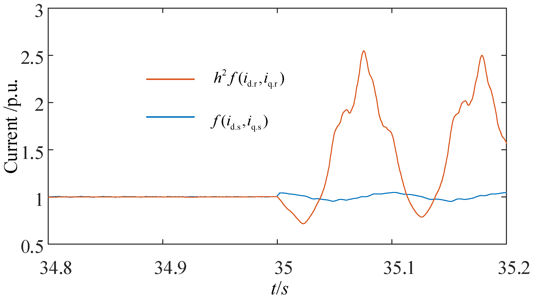
- According to Equations (12), (15) and (16), is calculated by using the dq-axis stator and rotor currents, which is no longer equal to 0 after a rotor winding short-circuit fault occurs. This process is a simple algebraic operation; the computational burden is small and can be realized quickly.
- (3)
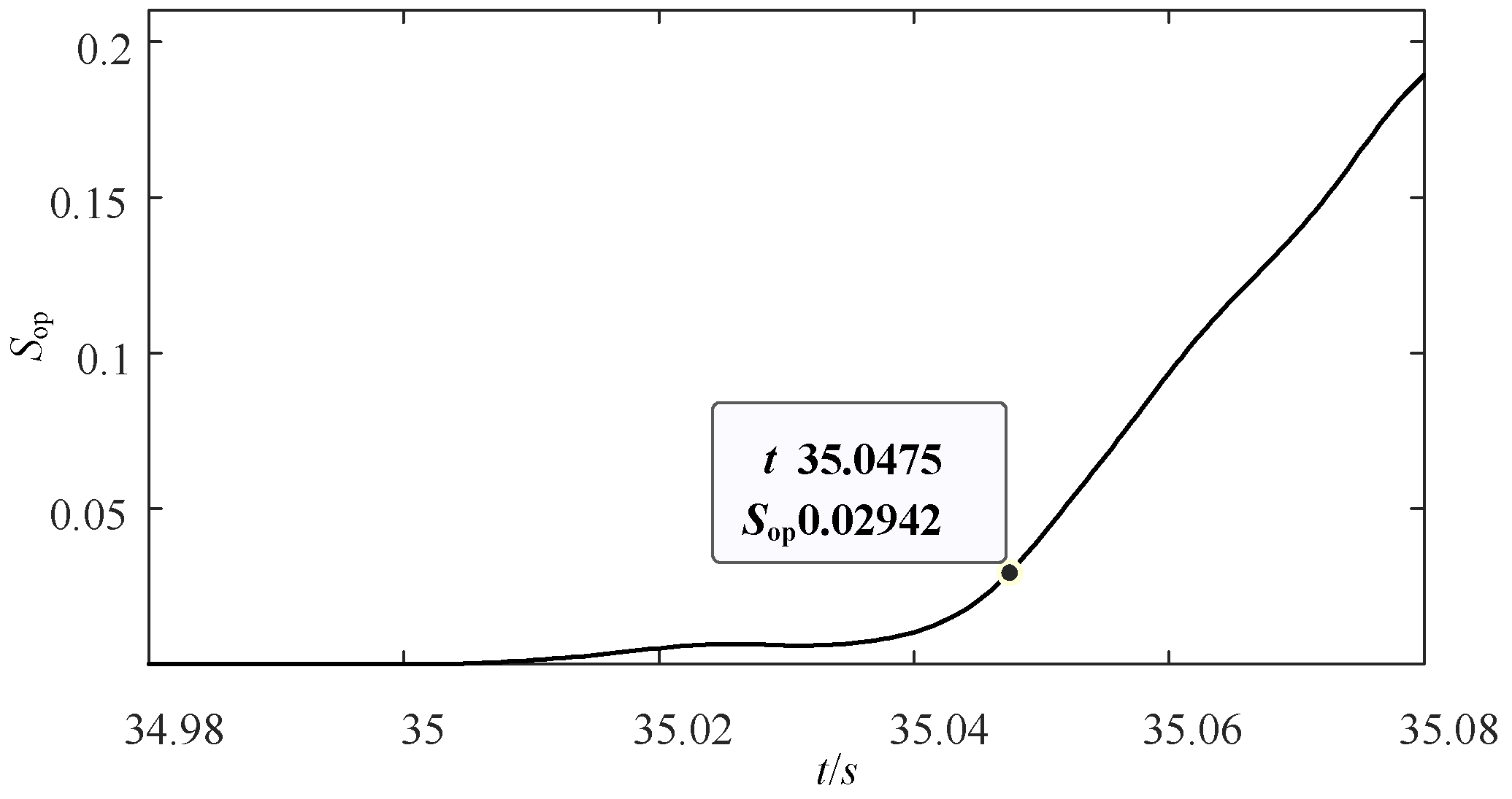
- The protection action value is calculated according to Equation (18), and the protection outlet mode is determined according to the size of the protection action value. This process requires the protection device to have a memory storage function, which is easy to implement. The existing protection device can store the intermediate calculation results in RAM, and can quickly exchange data with the CPU. Thus, the protection action value in Equation (18) can be obtained quickly by invoking the stored results. In addition, this process is a discrete integral operation, its algorithm is not complicated and can be realized quickly.
3.2. Calculation Method of the Protection Setting Value
4. Simulation Analysis
4.1. Performance Analysis under Different Slip Ratios
4.2. Performance Analysis under Different Fault Types
4.3. Performance Comparison with Another Method
5. Conclusions
Author Contributions
Funding
Institutional Review Board Statement
Informed Consent Statement
Data Availability Statement
Conflicts of Interest
Nomenclature
| Acronym | |
| VSPSGM | Variable-speed pumped-storage generator-motor |
| DFIG | Doubly fed induction generator |
| RAM | Random access memory |
| CPU | Central processing unit |
| FFT | Fast Fourier transform |
| Variable/Parameter | |
| ia.s | The stator current of phase A |
| ib.s | The stator current of phase B |
| ic.s | The stator current of phase C |
| Is | The amplitude of stator phase current |
| ωs | The stator angular frequency |
| φas | The stator A-phase current angle |
| id.s | The d-axis current at stator side obtained by Clark transformation |
| iq.s | The q-axis current at stator side obtained by Clark transformation |
| ia.r | The rotor current of phase A |
| ib.r | The rotor current of phase B |
| ic.r | The rotor current of phase C |
| Ir | The amplitude of rotor phase current |
| ωr | The rotor angular frequency |
| φar | The rotor A-phase current angle |
| id.r | The d-axis current at rotor side obtained by Clark transformation |
| iq.r | The q-axis current at rotor side obtained by Clark transformation |
| s | The slip ratio |
| Es | The amplitudes of the stator winding induced potential |
| Er | The amplitudes of the rotor winding induced potential |
| Ns | The number of series turns of each branch winding on the stator side |
| Nr | The number of series turns of each branch winding on the rotor side |
| kws | The fundamental wave winding factors of stator side |
| kwr | The fundamental wave winding factors of rotor side |
| Ie | The amplitude of short-circuit current |
| φe | The angle of short-circuit current |
| Ne | The turn number of the short-circuit coils |
| kek | The winding factor of the short-circuit coils |
| θ | The space electric angle |
| P | The number of pole-pairs |
| k | The harmonic order |
| Ir1 | The amplitude of the positive- and negative-sequence current components after the fault |
| φar1 | The phase angle of A-phase positive induced current after the fault |
| I+ | The induced-current amplitudes of the 1 + 2 s harmonic components |
| I− | The induced-current amplitudes of the 1 − 2 s harmonic components |
| φa+ | The induced-current phase angles of the 1 + 2 s harmonic components |
| φa− | The induced-current phase angles of the 1 − 2 s harmonic components |
| p | Differential operator |
| Us | The stator branch voltage matrices |
| Ur | The rotor branch voltage matrices |
| Is | The stator branch current matrices |
| Ir | The rotor branch current matrices |
| Rs | The stator branch resistance matrices |
| Rr | The rotor branch resistance matrices |
| Lss | The stator inductance matrix |
| Lrr | The rotor inductance matrix |
| Lsr | The mutual inductance matrices of stator and rotor |
| Lrs | The mutual inductance matrices of rotor and stator |
| N | The sampling times in one power frequency cycle |
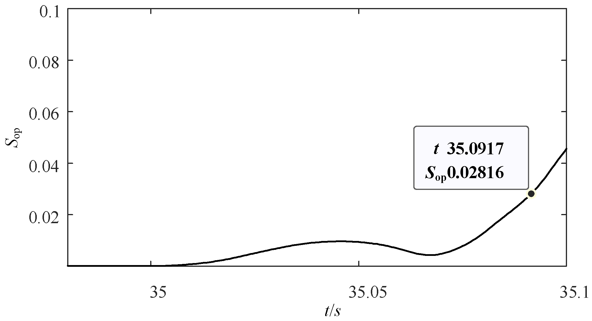
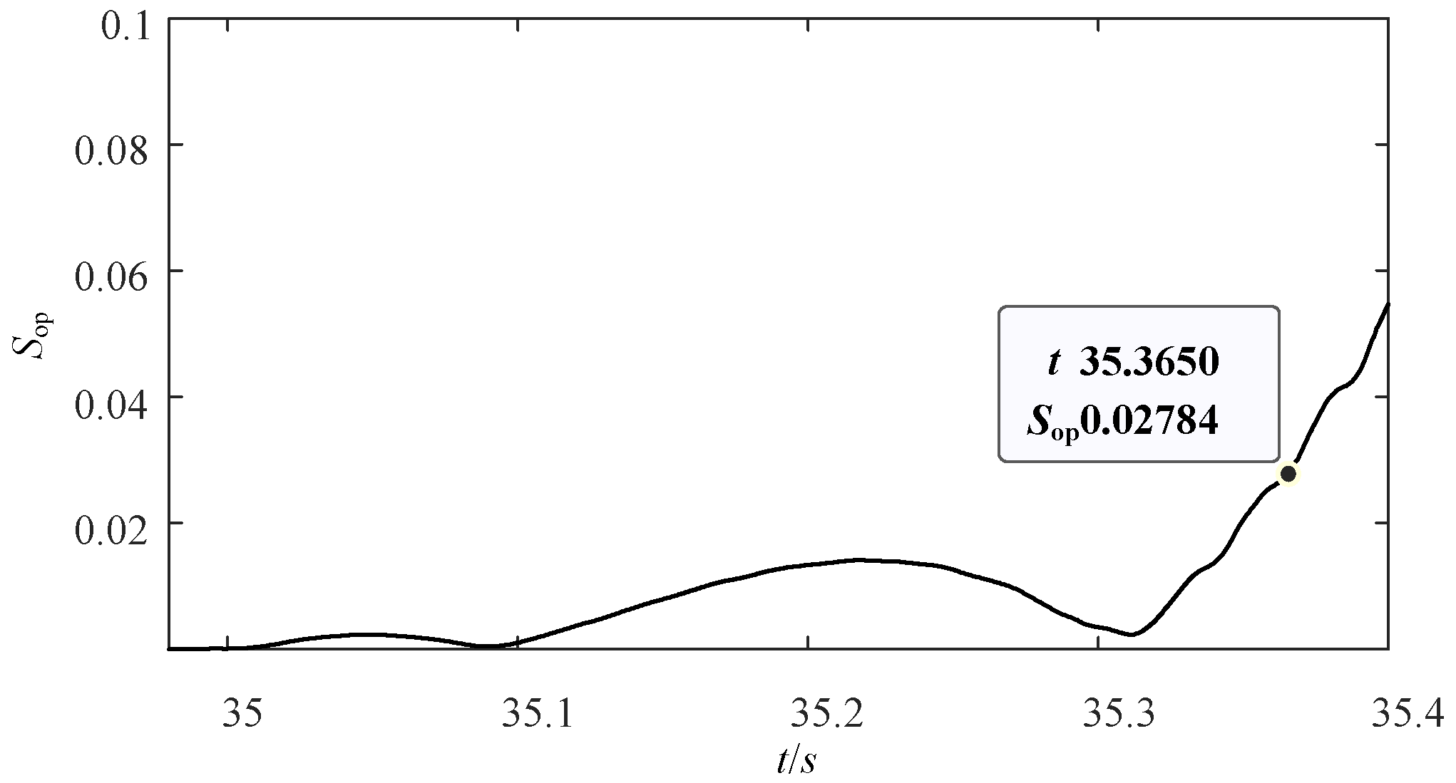
| Sop | The protection action value |
| Sset | The protection setting value |
| Sop.normal | The maximum protection action value under normal operation. |
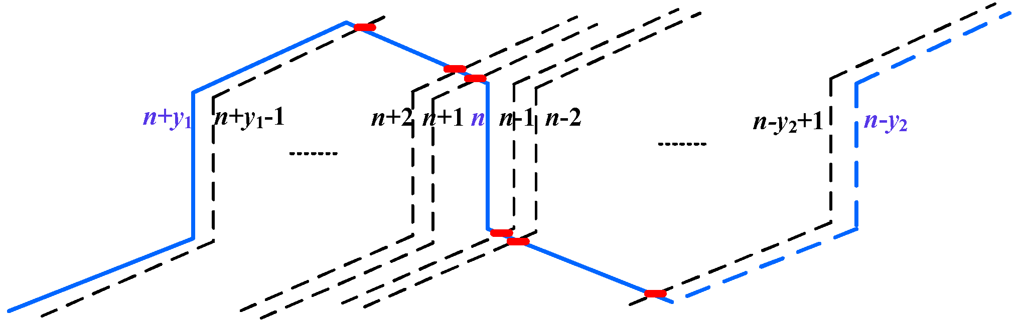
| Z | The slot number of the VSPSGM |
| y1 | The first pitch of the VSPSGM |
| y2 | The second pitch of the VSPSGM |
| Krel | The reliability coefficient |
References
- Deng, Y.; Wang, P.; Morabito, A.; Feng, W.; Mahmud, A.; Chen, D.; Hendrick, P. Dynamic analysis of variable-speed pumped storage plants for mitigating effects of excess wind power generation. Int. J. Electr. Power Energy Syst. 2021, 135, 107453. [Google Scholar] [CrossRef]
- Zhang, Z.; Cai, X. Low-carbon dispatch considering operating characteristics of variable speed pumped storage. Pro. CSEE 2016, 36, 51–60. [Google Scholar]
- Han, X.; Ding, L.; Chen, G. Key technologies and research prospects for cascaded hydro-photovoltaic-pumped storage hybrid power generation system. Trans. China Electrotech. Soc. 2020, 35, 2711–2722. [Google Scholar]
- Tianhui, L.; Ming, T.; Boyan, J. Modeling simulation and diagnosis analysis of inter-turn short circuits fault in generator rotor. High Volt. Eng. 2019, 45, 3932–3940. [Google Scholar]
- Orchuk, S. Synchronous Motors: Methods for Quantifying Rotor Condition. IEEE Ind. Appl. Mag. 2019, 25, 44–54. [Google Scholar] [CrossRef]
- Wang, L.; Li, Y.; Li, J. Diagnosis of Inter-Turn Short Circuit of Synchronous Generator Rotor Winding Based on Volterra Kernel Identification. Energies 2018, 11, 2524. [Google Scholar] [CrossRef]
- Zhou, G.; Li, Y.; Wan, S. Analysis on rotor unbalanced electromagnetic force of generator under rotor interturn short circuit fault. Trans. China Electrotech. Soc. 2012, 27, 120–127. [Google Scholar]
- Tang, S.; Chen, X.; Zheng, S. Fault diagnosis method of motor bearing based on attention and multi-scale convolution neural network. Electr. Eng. 2020, 21, 32–38. [Google Scholar]
- Chen, J.; Ye, H. Research on protection of internal short circuit in rotor winding of variable speed pumped-storage generator-motor. Electr. Power 2021, 54, 121–127. [Google Scholar]
- Mohammad, E.; Carlos, A. Novel differential protection technique for doubly fed induction machines. IEEE Trans. Ind. Appl. 2019, 55, 3697–3706. [Google Scholar]
- Wei, S.; Ren, Z.; Fu, Y. Early stage inter-turn faults detection technique for the rotor windings of offshore wind dfigs based on the differential value of two-side linkage observation. Pro. CSEE 2019, 39, 1470–1479. [Google Scholar]
- Abdesselam, L.; Ammar, M. Online computational tools dedicated to the detection of induction machine faults. Int. J. Electr. Power Energy Syst. 2013, 44, 752–757. [Google Scholar]
- Stefani, A.; Yazidi, A.; Rossi, C. Double fed induction machines diagnosis based on signature analysis of rotor modulating signals. IEEE Trans. Ind. Appl. 2008, 44, 1711–1721. [Google Scholar] [CrossRef]
- Yin, X.; Qiao, J.; Wang, Y. Optimal configuration of main protection for a variable speed pumped storage power generator based on internal fault simulation. Power Syst Prot. Control 2022, 13, 1–10. [Google Scholar]
- Huamin, N.; Lin, G. Simulation and experimental research on internal faults of rotor winding in ac excitation generator-motor based on the multi-loop theory. Hydropower Pumped Storage 2021, 7, 34–42. Available online: https://kns.cnki.net/kcms/detail/detail.aspx?dbcode=CJFD&dbname=CJFDLAST2021&filename=DBGC202104008&uniplatform=NZKPT&v=Gq5STmDu5FoerN971O8crSHgYRMrMCI99UaXSD7sCambLWFjBzoixJVvW7CKvRsv (accessed on 1 August 2022).
- He, R.; Qiao, J.; Peng, Y.; Yin, X.; Wang, Y.; Zhang, H.; Wang, W. A Rotor Winding Internal Short-Circuit Fault Protection Method for Variable-Speed Pumped Storage Units. Appl. Sci. 2022, 12, 7783. [Google Scholar] [CrossRef]
- Wei, S.; Zhang, L.; Fu, Y. Early fault detection based on the Park’s vector locus ovality for inter-turn faults in stator windings of the offshore wind DFIG. Pro. CSEE 2017, 37, 3001–3009. [Google Scholar]
- Mansouri, M.; Nayeripour, M. Internal electrical protection of wind turbine with doubly fed induction generator. Renewable Sustain. Energy Rev. 2016, 55, 840–855. [Google Scholar] [CrossRef]
- Gholam, R.; Gholam, R. Broken rotor bar and rotor eccentricity fault detection in induction motors using a combination of discrete wavelet transform and Teager–Kaiser energy operator. IEEE Trans. Energy Convers 2022, 37, 2199–2206. [Google Scholar]
- Shiyong, X.; Baojun, G.; Zhihui, L. Multi-loop model for fractional pole-path ratio synchronous generators with stator winding internal faults. IET Electr. Power Appl. 2020, 14, 2687–2696. [Google Scholar]
- Yuguang, S.; Wang, S. Analysis of armature inter-turn fault in the multiphase synchronous generator-rectifier system. IET Electr. Power Appl. 2019, 13, 871–880. [Google Scholar]
- Hao, L.; Li, J. Characteristic analysis of short-circuit fault in rotor winding of nuclear power multi-phase annular brushless exciter. Trans. China Electrotech. Soc. 2020, 35, 1251–1261. [Google Scholar]
- Huamin, N.; Lin, G.; Yuguang, S. Simulation and Experimental Research on Stator Winding Internal Faults of AC Excitation Machine Based on Multi-Loop Theory. Pro. CSEE 2019, 39, 3666–3684. [Google Scholar]
- Lv, Z.; Wang, D.; Lin, N. Analysis and Calculation of DC Side Short-Circuit Current of High-Speed Staggered Pole Hybrid Excitation Generator. Trans. China Electrotech. Soc. 2020, 35, 1251–1261. [Google Scholar]
- Li, W.; Qiao, J.; Wang, Y.; Liu, R.; Lv, T.; Yin, X. Fault Diagnosis Method of Stator Windings Short Circuit for Variable Speed Pumped Storage Unit Based on Park Transform. In Proceedings of the CEEPE, Chongqing, China, 22–24 April 2022; pp. 507–512. [Google Scholar] [CrossRef]


| Parameter | Stator | Rotor |
|---|---|---|
| Slot number (Z) | 252 | 294 |
| Winding form | Double-layer lap winding | Double-layer wave winding |
| Number of parallel branches | 4 | 2 |
| Number of coils per branch | 21 | 49 |
| The first pitch (y1) | 15 | 21 |
| The second pitch (y2) | 14 | 21 |
| Rated current/A | 12,317 | 6400 |
| Faults in the Same Branch with Different Short Turns | Faults between Two Branches in the Same Phase | Faults between Phases | Total | |
|---|---|---|---|---|
| In-slot faults | 252 | 42 | 0 | 294 |
| End faults | 1584 | 1944 | 8232 | 11,760 |
| Total | 1836 | 1986 | 8232 | 12,054 |
| Faults in the Same Branch with Different Short Turns | Faults between Two Branches in the Same Phase | Faults between Phases | Total | |
|---|---|---|---|---|
| In-slot faults | 205 | 35 | 0 | 240 |
| End faults | 1048 | 1158 | 7974 | 10,180 |
| Total | 1253 | 1193 | 7974 | 10,420 |
| Faults in the Same Branch with Different Short Turns | Faults between Two Branches in the Same Phase | Faults between Phases | Total | |
|---|---|---|---|---|
| In-slot faults | 222 | 36 | 0 | 258 |
| End faults | 1290 | 1467 | 8194 | 10,951 |
| Total | 1512 | 1503 | 8194 | 11,209 |
| Faults in the Same Branch with Different Short Turns | Faults between Two Branches in the Same Phase | Faults between Phases | Total | |
|---|---|---|---|---|
| In-slot faults | 226 | 36 | 0 | 262 |
| End faults | 1554 | 1906 | 8232 | 11,692 |
| Total | 1780 | 1942 | 8232 | 11,954 |
Publisher’s Note: MDPI stays neutral with regard to jurisdictional claims in published maps and institutional affiliations. |
© 2022 by the authors. Licensee MDPI, Basel, Switzerland. This article is an open access article distributed under the terms and conditions of the Creative Commons Attribution (CC BY) license (https://creativecommons.org/licenses/by/4.0/).
Share and Cite
Qiao, J.; Wang, Y.; He, R.; Wang, W.; Yin, X.; Peng, Y.; Zhang, H. Rotor Winding Short-Circuit-Fault Protection Method for VSPSGM Combining the Stator and Rotor Currents. Appl. Sci. 2022, 12, 9051. https://doi.org/10.3390/app12189051
Qiao J, Wang Y, He R, Wang W, Yin X, Peng Y, Zhang H. Rotor Winding Short-Circuit-Fault Protection Method for VSPSGM Combining the Stator and Rotor Currents. Applied Sciences. 2022; 12(18):9051. https://doi.org/10.3390/app12189051
Chicago/Turabian StyleQiao, Jian, Yikai Wang, Rufei He, Wenhui Wang, Xianggen Yin, Yumin Peng, and Hao Zhang. 2022. "Rotor Winding Short-Circuit-Fault Protection Method for VSPSGM Combining the Stator and Rotor Currents" Applied Sciences 12, no. 18: 9051. https://doi.org/10.3390/app12189051
APA StyleQiao, J., Wang, Y., He, R., Wang, W., Yin, X., Peng, Y., & Zhang, H. (2022). Rotor Winding Short-Circuit-Fault Protection Method for VSPSGM Combining the Stator and Rotor Currents. Applied Sciences, 12(18), 9051. https://doi.org/10.3390/app12189051