Abstract
Cervical laminoplasty is a useful for treatment for cervical myelopathy. However, this procedure has limitations for kyphotic cervical alignments. We used the finite element (FE) analysis and investigated the biomechanical changes in intact and laminoplasty models with lordosis, straight, and kyphosis cervical alignments. A three-dimensional FE model of the cervical spine (C2–C7) with ligaments was created from computer tomography. The model was modified with the following cobb angles (a) intact–lordotic model (intact–L; C2–C7 angle: −10°), (b) intact–straight model (intact–S; C2–C7 angle: 0°), and (c) intact–kyphotic model (intact–K; C2–C7 angle: 10°). The C3–C6 laminoplasty was conducted on the three intact models, represented by the laminoplasty–lordosis model (LM–L), laminoplasty–straight model (LM–S), and laminoplasty–kyphosis model (LM–K), respectively. Pure moment with compressive follower load of 100 N to represent the weight of the head/cranium and cervical muscle stabilization was applied to these models and the range of motion (ROM), annular stress, nucleus stress and facet forces were analyzed. ROM of intact–K and LM–K increased when compared to the other models. The LM–K had the highest mobility with 324% increase in ROM observed under extension, compared to LM–L. In addition, the annular stresses and nucleus stresses in intact–K and LM–K were higher compared to the other models. The maximum increase in annular stresses was about 309% in LM–K compared to the LM–L, observed at the C3–C4 segment. However, the facet contact forces were lower in the intact–K and LM–K, compared to the other models. Cases with cervical kyphosis alignment are at a disadvantage compared to cases with lordosis or straight alignment and should be treated with caution.
1. Introduction
In cervical spondylotic myelopathy (CSM), cervical disc herniation (CDH), and cervical ossification of the posterior longitudinal ligament (C-OPLL), asymptomatic patients with radiculopathy or myelopathy may be considered for surgical decompression [1]. Laminoplasty is a decompression procedure of the lamina for the spinal cord with positive surgical outcomes and improved techniques [2]. Although anterior decompression and fixation is also an important technique for decompression of the spinal cord, laminoplasty is often chosen because it allows for a wider decompression range and is relatively easy to perform [3,4]. However, complications such as increased kyphosis and axial pain may occur more often after conducting laminoplasty compared to anterior decompression and fixation because laminoplasty invades the cervical posterior ligament complex, which can disturb the cervical sagittal balance [5]. Specifically, laminoplasty for straight or kyphotic curvatures of the cervical spine is not recommended because the laminoplasty may not create enough posterior migration or may cause impingement, stretch injury of the spinal cord, postoperative kyphotic deformity, and loss of range of motion (ROM) [6,7].
There are no reports that have examined the extent to which the ROM of the cervical spine, stresses on the intervertebral discs and facet joint contact biomechanics change when the laminoplasty procedure is performed for different alignments. We examined the biomechanical changes on when double-door laminoplasty [8] is performed on cervical spines with lordosis, straight, and kyphosis alignments. We hypothesized that the ROM, stress contribution of the disc, intervertebral body, and facet loads may change for the cervical alignment if the same laminoplasty was conducted. This study would provide mechanically important information for a physician performing laminoplasty and whether additional anterior decompression and fixation or posterior fixation with instrumentation is necessary, depending on the cervical spine alignment.
In this study, a C2–C7 three-dimension (3D) FE model of a cervical spine with three alignments (lordosis, straight, and kyphosis) was created to examine how stress and mobility in the cervical spine changed for different alignments post double-door laminoplasty surgery.
2. Materials and Methods
2.1. Model Development
A validated cervical spine (C2-C7) FE model was developed using computed tomography (CT) images of a healthy adult subject [9]. Use of the CT scans was approved by the Institutional Review Board of the authors’ affiliated institutions and informed consent was obtained from the patient and documented in the electronic medical record. Three-dimensional reconstruction of the CT scans was performed in MIMICS v15.0 (Materialise, Leuven, Belgium) and mesh construction was performed in IA-FEMESH (Iowa, IA, USA) with hexahedral elements. The meshed structures of the vertebrae and intervertebral discs was then assembled in ABAQUS software (Dassault Systèmes, Simulia Inc., Providence, RI, USA). Ligaments including the anterior longitudinal ligament (ALL), posterior longitudinal ligament (PLL), interspinous ligament (ISL), supraspinous ligament (SSL), capsular ligament (CL), and ligamentum flavum (LF) were incorporated onto the FE model via truss elements. The cortical bone was modeled as a shell with a 0.5 mm shell surrounding the inner cancellous bone. The intervertebral discs composed of the annulus fibrosis, which consisted of ground substances and contained embedded fibers oriented at ±25° [10], and the nucleus pulposus. Facet joints were modelled using surface-surface sliding contacts and Kushka’s joints present in the lower intervertebral discs were modelled using GAPUNI elements [11]. The FE model material properties are summarized in Table 1 [12,13,14].

Table 1.
Material properties assigned to the finite element model [12,13,14].
2.2. Cervical Alignments
Cobb Angles were used as cervical spine parameters and calculated per the 4-line method described by Harrison et al [15,16]. This method involves drawing two parallel lines on the lateral radiograph. The first is a line from the inferior endplate of C2 to the posterior margin of the spinous process and the second parallel line is drawn from the inferior endplate of C7. Perpendicular lines are drawn from the two lines mentioned above and the angle subtended between the intersection of the perpendicular lines is defined as the cervical curvature angle. The angles created include the spino-cranial angle (SCA) which is defined as the angle between the C7 slope and the straight line joining the middle of the C7 end plate and the middle of the sella turcica. The cervical sagittal vertical axis (cSVA) is defined as the distance from a vertical plumb line dropped from the center of the C2 vertebral body to the posterior superior corner of the C7 vertebra). The FE model used for cervical validation had a C2–C7 Cobb angle of −5°. This FE model was modified, and the three alignments were created by applying displacement/rotations to the cervical vertebrae until the appropriate alignment was obtained. For example, for creating a kyphotic model, the C7 vertebra was fixed and rotation at C2 was applied until C2–C7 = 10° (kyphosis) was obtained. From this method, the following alignments were created (a) intact-lordotic model (intact-L; C2–C7 angle: −10°, cSVA: 25 mm, the C7 slope: 20°), (b) intact-straight model (intact-S; C2–C7 angle: 0°, cSVA: 31 mm, the C7 slope: 22°), and (c) intact-kyphotic model (intact-K; C2–C7 angle: 10°, cSVA: 38 mm, the C7 slope: 24°) (Figure 1a–c).
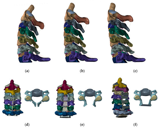
Figure 1.
The intact (C2–C7) FE model. (a) Lordosis model. (b) Straight model. (c) Kyphosis model. The laminoplasty model. (d) The spinous process was partially resected, about 4 mm of bone from the center of the lamina was cut, and the medial side of both the facet joints was shaved (C3–C6). (e) The lamina was opened to the lateral sides. (f) The laminoplasty model (C3–C6).
2.3. Cervical Laminoplasty
Double door laminoplasty was simulated on the three intact models by performing osteotomy at the central spinous process and lamina. First, the ISL and SSL were resected. Next, the spinous process was partially resected. About 4 mm of bone from the center of the lamina was cut, and the medial side of both the facet joints was shaved so that lamina could be opened (Figure 1d,e). The LF of C2–C3 and C6–C7 was excised because these interfered with the opening of the lamina, which was opened to the right and left sides (Figure 1f). Moreover, it widened the narrow canal and simulated the decompression of the spinal cord posteriorly. The artificial bone with 4 mm height and 8 mm depth was then placed to fit into the opened lamina (Figure 1f). The artificial bones were attached to the either side of the lamina via “TIE” constraint formulation in ABAQUS to represent firm attachment of bone graft to the lamina. The material properties of the artificial bone were the same as the cortical bone. The same procedure was used to create a double-door laminoplasty model of C3–C6, in which the lamina and the artificial bone were set to be connected in all directions (Figure 1f). The C3–C6 double door laminoplasty using this methodology was conducted on the intact–lordosis, intact–straight, and intact–kyphosis configurations. The resulting laminoplasty models were represented by laminoplasty–lordosis model (LM–L), laminoplasty–straight model (LM–S), and laminoplasty–kyphosis model (LM–K).
2.4. Loads and Boundary Conditions
A 1.5 Nm pure moment was applied onto the C2 odontoid process to simulate six motions: flexion/extension, lateral (left and right) bending, axial (right and left) rotations. The inferior endplate of C7 was fixed. The model was subjected to preloads which included a 100N follower load to represent the weight of the head/cranium and cervical muscles stabilizing the spine [17].
2.5. Data Analyses
The ROM, annular stresses, intradiscal (nucleus) stresses, and facet contact forces were calculated for intact, LM–L, LM–S, and LM–K. Annular stresses and nucleus stresses were noted by the maximum von Mises stress. For the facet joint force, the data for facet forces were averaged for the left/right facets. For example, if C3 ROM was 5° and C4 ROM was 3°. Then C3–C4 ROM would be 5 – 3 = 2°.
The annulus and nucleus stress are calculated directed by the Abaqus software. We reported the maximum von Mises stress observed on the nucleus/annulus. Similarly, for facet contact forces, the Abaqus software calculated the maximum force on each facet joint. We averaged the facet contact force observed on right/left facet.
The maximum von Mises stress was reported for the annulus and nucleus stress. Facet contact maximum forces were also reported and averaged for each right/left facet.
The percentage change (%) was calculated using the following equation:
3. Results
3.1. ROM
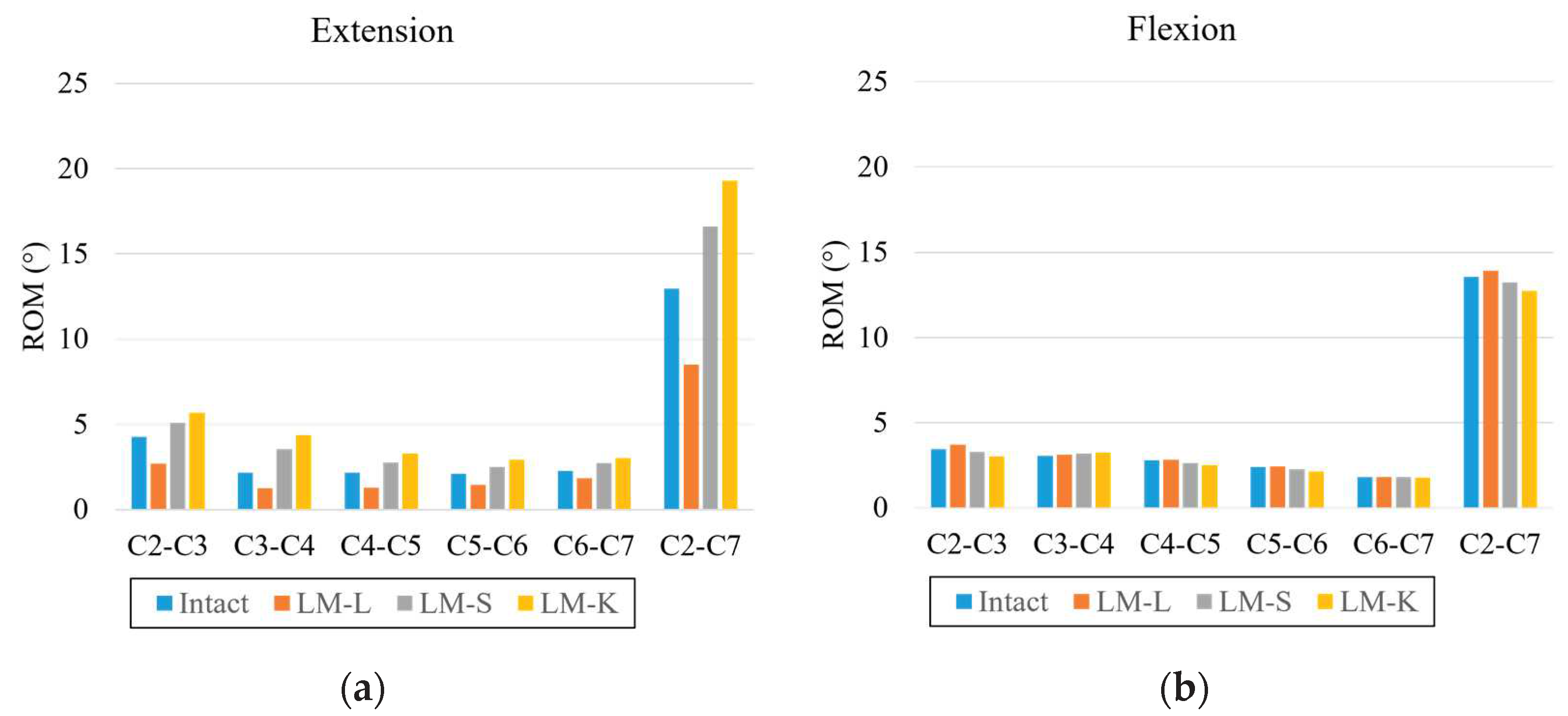
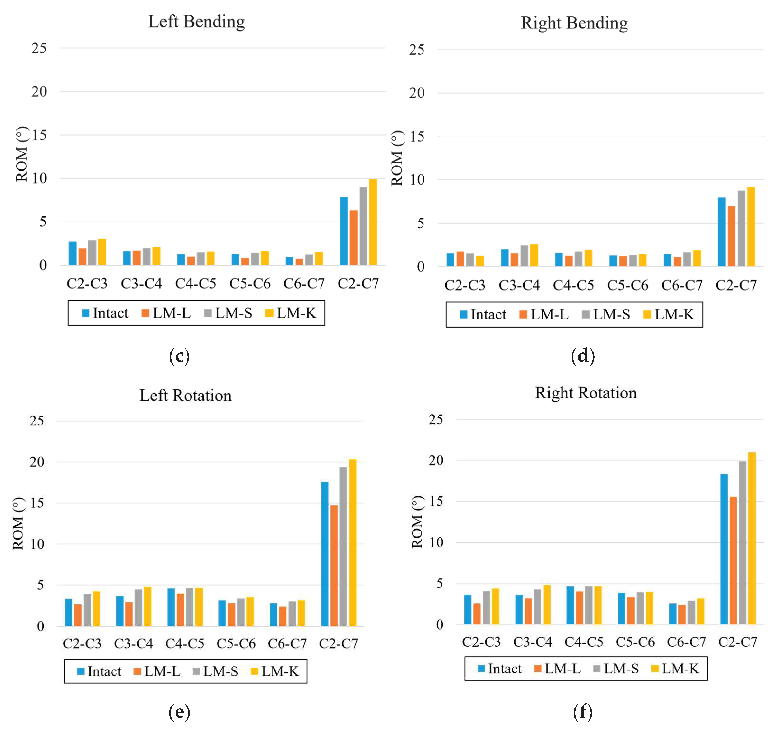
In extension, LM–L models’ ROM decreased by 35%, and LM–S and LM–K models’ ROM increased by 28% and 49% at C2–C7 compared to the intact model. In flexion, LM–L model’s ROM increased by 3%, and LM–S and LM–K model’s ROM decreased at C2–C3, C3–C4, C4–C5, and C2–C7 compared to the intact model. In left bending, LM–L model’s ROM decreased by 20%, and LM–S and LM–K model’s ROM increased by 15% and 26% at C2–C7 compared to the intact model. In right bending, LM–L model’s ROM decreased by 13%, and LM–S and LM–K model’s ROM increased by 10% and 15% at C2–C7 compared to the intact model. In left rotation, LM–L model’s ROM decreased by 16%, and LM–S and LM–K model’s ROM increased by 10% and 16% at C2–C7 compared to the intact model. In right rotation, LM–L model’s ROM decreased by 15%, and LM–S and LM–K model’s ROM increased by 8% and 15% at C2–C7 compared to the intact model (Figure 2).
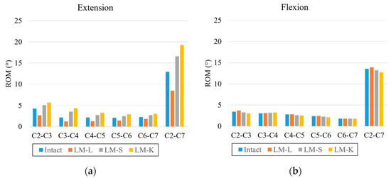
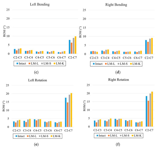
Figure 2.
Range of motion: (a) extension, (b) flexion, (c) left bending, (d) right bending, (e) left rotation, and (f) right rotation. The vertical axis is the angle (degree); the horizontal axis is each intervertebral level.
3.2. Annular Stress
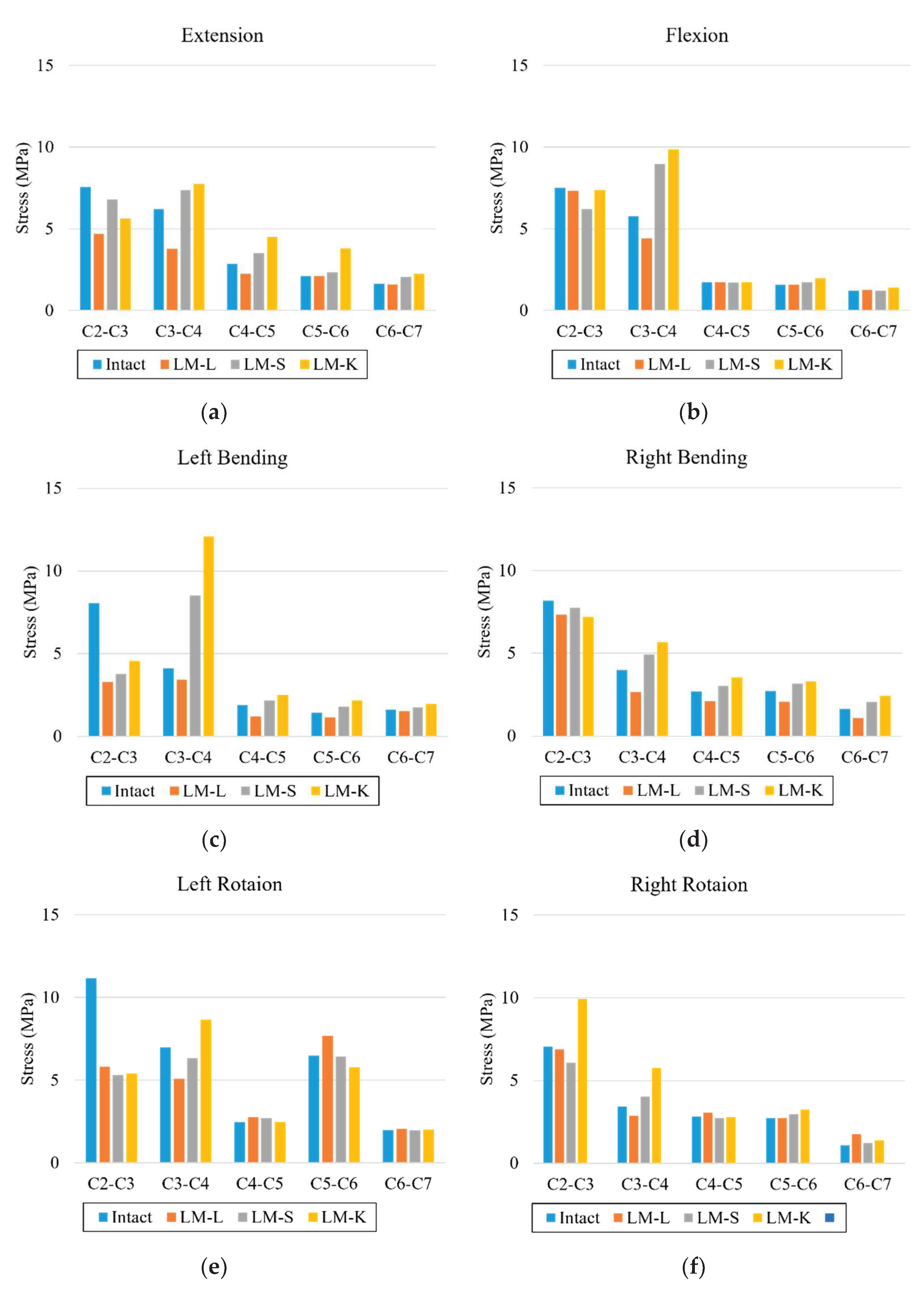
In extension, the annular stresses decreased by 37%, 39%, and 21% at C2–C3, C3–C4, and C4–C5 in the LM–L when compared to the intact model. The annular stresses increased by 18%, 23%, and 11% at C3–C4, C4–C5, and C5–C6 in the LM–S and by 24%, 59%, and 80% at C3–C4, C4–C5, and C5–C6 in the LM–K when compared to the intact model. In flexion, the annular stresses decreased by 23% at C3–C4 in the LM–L when compared to the intact model. The annular stresses increased by 55% at C3–C4 in the LM–S and by 71% at C3–C4 in the LM–K when compared to the intact model. In left bending, the annular stresses decreased by 16% at C3–C4 in the LM–L when compared to the intact model. The annular stresses increased by 108% at C3–C4 in the LM–S and by 194% at C3–C4 in the LM–K when compared to the intact model. In right bending, the annular stresses decreased by 34% at C3–C4 in the LM–L when compared to the intact model. The annular stresses increased by 24% at C3–C4 in the LM–S and by 48% at C3–C4 in the LM–K when compared to the intact model. In left rotation, the annular stresses decreased by 27% in the LM–L and by 9% at C3–C4 in the LM–S when compared to the intact model. The annular stresses increased by 24% at C3–C4 in the LM–K when compared to the intact model. In right rotation, the annular stresses decreased by 16% at C3–C4 in the LM–L when compared to the intact model. The annular stresses increased by 18% at C3–C4 in the LM–S and by 69% at C3–C4 in the LM–K when compared to the intact model (Figure 3).

Figure 3.
Annulus pressure: (a) extension, (b) flexion, (c) left bending, (d) right bending, (e) left rotation, and (f) right rotation. The vertical axis is stress (egapascal; Mpa); the horizontal axis is each intervertebral level.
3.3. Nucleus Stresses
In extension, the nucleus stresses decreased in the LM–L, LM–S and LM–K models compared to the intact model in all levels. For flexion, nucleus stresses increased in the LM–L model in comparison with the LM–S and LM–K. In left bending, the nucleus stresses increased in the LM–K compared to the LM–L and LM–S models except for C2–C3. In right bending, higher nucleus stresses were observed at all levels for the LM–K compared to the intact, LM–L and LM–S models. In left and right axial rotation, the nucleus stress was increased in the LM–K model when compared to the intact, LM–L and LM–S models (Figure 4).
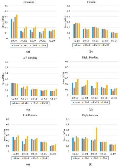
Figure 4.
Nucleus stresses: (a) extension, (b) flexion, (c) left bending, (d) right bending, (e) left rotation, and (f) right rotation. The vertical axis is stress (Mpa); the horizontal axis is each intervertebral level.
3.4. Facet Contact Forces
In extension, the facet contact forces at all levels for LM–L increased by 20–60% respectively compared to the intact model. The facet contact forces at all levels for LM–S and LM–K decreased by 30–45% and 58–95% respectively compared to the intact model. In lateral bending, the facet contact forces at all levels for LM–L increased by 15–27% respectively compared to the intact model. The facet contact forces at all levels for LM–S and LM–K decreased by 10–46% and 19–57% respectively compared to the intact model. In rotation, the facet contact forces at all levels for LM–L increased by 14–89% respectively compared to the intact model. The facet contact forces at all levels except for C2–C3 for LM–S decreased by 24–45% respectively compared to the intact model. The facet contact forces at all levels for LM–K decreased by 43–90% respectively compared to the intact model (Figure 5).
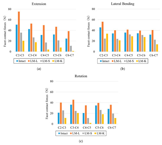
Figure 5.
Facet contact forces. (a) extension, (b) lateral bending, (c) axial rotation. Vertical axis is force (N), horizontal axis is each intervertebral level.
4. Discussion
This study aimed to investigate the biomechanical changes for lordotic, straight, and kyphotic cervical sagittal alignment models following cervical laminoplasty.
The cervical spine is an important part of the body that supports the head and provides sufficient mobility and protection to the cervical spinal cord, but once neurological symptoms occur, anterior or posterior decompression (laminectomy or laminoplasty) may be required. Laminoplasty is usually reported to increase the stability of the cervical spine. Seichi et al. reported that mean mobility decreased from 36° to 8° following double door laminoplasty [18]. Additionally, Ratliff and Cooper reported that the ROM was reduced by 50% for double-door laminoplasty relative to pre-operation measurements [19]. The effect of cervical alignment on surgical intervention is debated. There are few reports on what Cobb angles are acceptable for cervical laminoplasty. Lee reported that patients with straight or lordosis (range, 1–14°) may also be suitable for laminoplasty [20]. In general, it has been reported that laminoplasty is not effective for patients with C-OPLL and having cervical spine kyphosis along with high cSVA [7,21,22]. The clinical review reported the ranges of two sagittal parameters for desired post-operative clinical outcomes: C7 slope, average value 20°, must not be higher than 40° and cSVA must be less than 40 mm (mean value 20 mm) [23]. In this analysis, for extension, both bending and both rotations, the LM–L model only showed a decrease in ROM compared to other models. The ROM became higher as kyphosis increased. These results agree with reports in the literature that claimed that complications such as increased kyphosis may occur after conducting laminoplasty for cases with kyphosis alignment [6,7]. The annulus stresses generally increased as the kyphosis increased. The largest differences for the annulus stresses between the intact and laminoplasty models were observed in C3–C4. This could be because the posterior ligaments were stretched as kyphosis increased, and the laminoplasty damaged the posterior ligaments, resulting in increased stress in the annulus. For nucleus stresses, lower stresses were observed for the LM–L model than for the intact model in all motions except for left bending. The facet forces were the highest in the LM–L model, which may be due to the distance between the facet joints in that specific alignment. In this analysis, the spinous processes, lamina, and the artificial bones were also closer in the lordotic alignment, but they never came in contact during any motion. The facet forces in the LM–S model were higher than the intact model in flexion, bending, and rotation motions, especially in C2–C3, possibly due to stabilization by laminoplasty. Conversely, in kyphosis, there was a possibility that the load was further decreased by laminoplasty. The facet force was reduced in all motions, and the function of the facet joint can be weakened. The results of the ROM, annulus stresses, nucleus stresses and facet forces suggested that laminoplasty in cervical kyphosis alignments may result in negative clinical outcomes. Conversely, Kim showed that patients having within 10° of cervical kyphosis had similar postoperative outcome compared to patients with normative cervical lordotic alignment following posterior decompression with laminoplasty [6]. Matsunaga reported successful neurologic outcomes for patients with up to 13 degrees of kyphosis after cervical laminoplasty [24]. Thus, the debate continues about sagittal alignment and posterior procedures, and it will be necessary to analyze a model with increased kyphosis angle in the future.
The published studies on the biomechanical effects of laminoplasty of the cervical spine can be largely divided into FE analysis and cadaver analysis studies. In FE analysis studies, reports of laminectomy are far more common than reports of laminoplasty [25]. We did not analyze laminectomy in this study. Hashiguchi reported the difference in stresses in the cervical spine after different laminoplasty surgeries including open door laminoplasty, French door laminoplasty, and double-door laminoplasty. They reported that laminoplasty was more stable than the intact model [26]. In our study, the results were similar only for LM–L. Kode reported that during flexion, the percent changes in C2–T1 ROM of LM resulted in a 20% increase, and in left bending, a decrease of 20% was observed. Similarly, left axial rotation resulted in a 15% decrease in motion at C6–C7 after double-door laminoplasty [27]. In our study, LM–L showed the same trend; however, previous reports did not consider cervical alignment.
In cadaver analysis studies, Kubo reported three-dimensional kinematic changes after double-door cervical laminoplasty. They found that laminoplasty showed no significant differences in motion compared with intact except in axial rotation [28]. Subramaniam reported that open-door laminoplasty left the spine in a significantly more stable condition than laminectomy after comparing biomechanical stability during flexion and extension [29]. These results indicated the contribution of laminoplasty to stability. Our results also showed a similar trend for LM–L. To the best of our knowledge, our study is the first to examine various sagittal alignments on the cervical spine.
There are several limitations to our study. The models do not include muscles, although the effect of musculature was addressed by the follower load technique [17]. Additionally, the only cervical alignments analyzed were lordotic, straight, and kyphosis alignments. A model with increased kyphosis should also be explored. The current study does not include a spinal cord, nor does it take osteoporosis or osteoarthritis into consideration, which may alter the material properties of the bone. Kyphosis of the thoracic spine and total spine alignment were also not considered. This model simulates an immediate postoperative scenario and does not consider conditions such as fusion and non-fusion of the lamina. The study also does not fully simulate the long-term outcome of laminoplasty. Although there are several methods of laminoplasty [26], the current study only analyzes double-door laminoplasty. FE analysis is a one-time event analyses for a single model. It does not allow for subsequent analysis, such as the evaluation of muscle training and other statistical factors due to rehabilitation. Therefore, multivariate analysis cannot be performed as in clinical analysis. However, our analysis was consistent with previous biomechanical and clinical studies [24,26,29]. Despite these limitations, this study provides valuable insight on the biomechanical outcome of laminoplasty in different cervical sagittal alignments.
5. Conclusions
An FE model created from medical images was used to analyze laminoplasty for different cervical sagittal alignments (lordotic, straight, and kyphotic). In the lordotic model, we observed reduction in ROM, annulus stress, and nucleus stress compared to the intact model. In the straight model, we observed higher ROM, annulus stress, and nucleus stress compared to intact and lordotic model. In the kyphotic model, we observed the highest increase in the ROM, annulus stress, and nucleus compared to the intact model. In summary, patient cases with a cervical kyphosis alignment are disadvantageous compared to a case with a lordotic or straight alignment and should be treated with caution when considering laminoplasty.
Author Contributions
Conceptualization, N.N.; data curation, M.M., N.N. and S.T.; formal analysis, M.M., N.N. and S.T.; funding acquisition, V.K.G.; methodology, N.N. and A.K.; project administration, N.N. and M.M.; supervision, V.K.G.; validation, M.M. and N.N.; visualization, S.T.; writing—original draft, N.N. and Y.K.; writing—review and editing, M.M., N.N., A.K., J.M. and V.K.G. All authors have read and agreed to the published version of the manuscript.
Funding
This research received no external funding.
Institutional Review Board Statement
The study was conducted according to the guidelines of the Declaration of Helsinki and was approved by the Institutional Review Board of The University of Toledo.
Informed Consent Statement
Informed consent was obtained from the subjects involved in the study.
Data Availability Statement
The data presented in this study are available.
Acknowledgments
The work was supported in part by the NSF Industry/University Cooperative Research Center at the University of California at San Francisco, University of Toledo, and Ohio State University.
Conflicts of Interest
The authors declare no conflict of interest.
References
- Boody, B.S.; Lendnerm, M.; Vaccaro, A.R. Ossification of the posterior longitudinal ligament in the cervical spine: A review. Int. Orthop. 2019, 43, 797–805. [Google Scholar] [CrossRef] [PubMed]
- Hirabayashi, S.; Kitagawa, T.; Yamamoto, I.; Yamada, K.; Kawano, H. Development and Achievement of Cervical Laminoplasty and Related Studies on Cervical Myelopathy. Spine Surg. Relat. Res. 2020, 4, 8–17. [Google Scholar] [CrossRef] [PubMed]
- Lee, N.J.; Kim, J.S.; Park, P.; Riew, K.D. A Comparison of Various Surgical Treatments for Degenerative Cervical Myelopathy: A Propensity Score Matched Analysis. Glob. Spine J. 2022, 12, 1109–1118. [Google Scholar] [CrossRef]
- Yoshii, T.; Egawa, S.; Chikuda, H.; Kaito, T.; Mori, K.; Koda, M.; Egawa, S.; Hasegawa, T.; Imagama, S.; Yoshida, M.; et al. A systematic review and meta-analysis comparing anterior decompression with fusion and posterior laminoplasty for cervical spondylotic myelopathy. J. Orthop. Sci. 2021, 26, 116–122. [Google Scholar] [CrossRef] [PubMed]
- Tang, J.A.; Scheer, J.K.; Smith, J.S.; Deviren, V.; Bess, S.; Hart, R.A.; Lafage, V.; Shaffrey, C.I.; Schwab, F.; Ames, C.P. The impact of standing regional cervical sagittal alignment on outcomes in posterior cervical fusion surgery. Neurosurgery 2015, 76 (Suppl. 1), S14–S21; Discussion S. [Google Scholar] [CrossRef] [PubMed]
- Kim, S.W.; Jang, S.B.; Lee, H.M.; Lee, J.H.; Lee, M.U.; Kim, J.W.; Yee, J.S. Analysis of Cervical Spine Alignment and its Relationship with Other Spinopelvic Parameters after Laminoplasty in Patients with Degenerative Cervical Myelopathy. J. Clin. Med. 2020, 9, 713. [Google Scholar] [CrossRef] [PubMed]
- Machino, M.; Yukawa, Y.; Hida, T.; Ito, K.; Nakashima, H.; Kanbara, S.; Morita, D.; Kato, F. Cervical alignment and range of motion after laminoplasty: Radiographical data from more than 500 cases with cervical spondylotic myelopathy and a review of the literature. Spine 2012, 37, E1243–E1250. [Google Scholar] [CrossRef]
- Kurokawa, R.; Kim, P. Cervical Laminoplasty: The History and the Future. Neurol. Med. -Chir. 2015, 55, 529–539. [Google Scholar] [CrossRef]
- Nishida, N.; Mumtaz, M.; Tripathi, S.; Kelkar, A.; Sakai, T.; Goel, V.K. Biomechanical Analysis of Posterior Ligaments of Cervical Spine and Laminoplasty. Appl. Sci. 2021, 11, 7645. [Google Scholar] [CrossRef]
- Kallemeyn, N.; Gandhi, A.; Kode, S.; Shivanna, K.; Smucker, J.; Grosland, N. Validation of a C2-C7 cervical spine finite element model using specimen-specific flexibility data. Med. Eng. Phys. 2010, 32, 482–489. [Google Scholar] [CrossRef]
- Mumtaz, M.; Zafarparandeh, I.; Erbulut, D.U. Investigation into Cervical Spine Biomechanics Following Single, Multilevel and Hybrid Disc Replacement Surgery with Dynamic Cervical Implant and Fusion: A Finite Element Study. Bioengineering 2022, 9, 16. [Google Scholar] [CrossRef] [PubMed]
- Finn, M.A.; Brodke, D.S.; Daubs, M.; Patel, A.; Bachus, K.N. Local and global subaxial cervical spine biomechanics after single-level fusion or cervical arthroplasty. Eur. Spine J. 2009, 18, 1520–1527. [Google Scholar] [CrossRef] [PubMed]
- Goel, V.K.; Clausen, J.D. Prediction of load sharing among spinal components of a C5-C6 motion segment using the finite element approach. Spine 1998, 23, 684–691. [Google Scholar] [CrossRef] [PubMed]
- Little, J.P.; Adam, C.J.; Evans, J.H.; Pettet, G.J.; Pearcy, M.J. Nonlinear finite element analysis of anular lesions in the L4/5 intervertebral disc. J. Biomech. 2007, 40, 2744–2751. [Google Scholar] [CrossRef]
- Ling, F.P.; Chevillotte, T.; Leglise, A.; Thompson, W.; Bouthors, C.; Le Huec, J.C. Which parameters are relevant in sagittal balance analysis of the cervical spine? A literature review. Eur. Spine J. 2018, 27 (Suppl. 1), 8–15. [Google Scholar] [CrossRef]
- Harrison, D.E.; Harrison, D.D.; Cailliet, R.; Troyanovich, S.J.; Janik, T.J.; Holland, B. Cobb method or Harrison posterior tangent method: Which to choose for lateral cervical radiographic analysis. Spine 2000, 25, 2072–2078. [Google Scholar] [CrossRef]
- Patwardhan, A.G.; Havey, R.M.; Carandang, G.; Simonds, J.; Voronov, L.I.; Ghanayem, A.J.; Meade, K.P.; Gavin, T.M.; Paxinos, O. Effect of compressive follower preload on the flexion-extension response of the human lumbar spine. J. Orthop. Res. 2003, 21, 540–546. [Google Scholar] [CrossRef]
- Seichi, A.; Takeshita, K.; Ohishi, I.; Kawaguchi, H.; Akune, T.; Anamizu, Y.; Kitagawa, T.; Nakamura, K. Long-term results of double-door laminoplasty for cervical stenotic myelopathy. Spine 2001, 26, 479–487. [Google Scholar] [CrossRef]
- Ratliff, J.K.; Cooper, P.R. Cervical laminoplasty: A critical review. J. Neurosurg. 2003, 98 (Suppl. 3), 230–238. [Google Scholar] [CrossRef]
- Lee, J.Y.; Sharan, A.; Baron, E.M.; Lim, M.R.; Grossman, E.; Albert, T.J.; Vaccaro, A.R.; Hilibrand, A.S. Quantitative prediction of spinal cord drift after cervical laminectomy and arthrodesis. Spine 2006, 31, 1795–1798. [Google Scholar] [CrossRef]
- Inose, H.; Yoshii, T.; Kimura, A.; Takeshita, K.; Inoue, H.; Maekawa, A.; Endo, K.; Furuya, T.; Nakamura, A.; Mori, K.; et al. Factors Negatively Influencing Postoperative Improvement after Laminoplasty in Degenerative Cervical Myelopathy. Clin. Spine Surg. 2021, 35, E230–E235. [Google Scholar] [CrossRef]
- Bridges, K.J.; Simpson, L.N.; Bullis, C.L.; Rekito, A.; Sayama, C.M.; Than, K.D. Combined Laminoplasty and Posterior Fusion for Cervical Spondylotic Myelopathy Treatment: A Literature Review. Asian Spine J. 2018, 12, 446–458. [Google Scholar] [CrossRef] [PubMed]
- Azimi, P.; Yazdanian, T.; Benzel, E.C.; Hai, Y.; Montazeri, A. Sagittal balance of the cervical spine: A systematic review and meta-analysis. Eur. Spine J. 2021, 30, 1411–1439. [Google Scholar] [CrossRef] [PubMed]
- Matsunaga, S.; Sakou, T.; Nakanisi, K. Analysis of the cervical spine alignment following laminoplasty and laminectomy. Spinal Cord 1999, 37, 20–24. [Google Scholar] [CrossRef]
- Khuyagbaatar, B.; Kim, K.; Park, W.M.; Lee, S.; Kim, Y.H. Increased stress and strain on the spinal cord due to ossification of the posterior longitudinal ligament in the cervical spine under flexion after laminectomy. Proc. Inst. Mech. Eng. H 2017, 231, 898–906. [Google Scholar] [CrossRef] [PubMed]
- Hashiguchi, A.; Kanchiku, T.; Nishida, N.; Taguchi, T. Biomechanical Study of Cervical Posterior Decompression. Asian Spine J. 2018, 12, 391–397. [Google Scholar] [CrossRef] [PubMed]
- Kode, S.; Kallemeyn, N.A.; Smucker, J.D.; Fredericks, D.C.; Grosland, N.M. The effect of multi-level laminoplasty and laminectomy on the biomechanics of the cervical spine: A finite element study. Iowa Orthop. J. 2014, 34, 150–157. [Google Scholar] [PubMed]
- Kubo, S.; Goel, V.K.; Yang, S.J.; Tajima, N. The biomechanical effects of multilevel posterior foraminotomy and foraminotomy with double-door laminoplasty. J. Spinal Disord. Tech. 2002, 15, 477–485. [Google Scholar] [CrossRef]
- Subramaniam, V.; Chamberlain, R.H.; Theodore, N.; Baek, S.; Safavi-Abbasi, S.; Senoglu, M.; Sonntag, V.K.H.; Crawford, N.R. Biomechanical effects of laminoplasty versus laminectomy: Stenosis and stability. Spine 2009, 34, E573–E578. [Google Scholar] [CrossRef] [Green Version]


Publisher’s Note: MDPI stays neutral with regard to jurisdictional claims in published maps and institutional affiliations. |
© 2022 by the authors. Licensee MDPI, Basel, Switzerland. This article is an open access article distributed under the terms and conditions of the Creative Commons Attribution (CC BY) license (https://creativecommons.org/licenses/by/4.0/).