Abstract
When constructing open excavation and adding stories on the upper part of an existing station structure, the new foundation pit contacts with the existing station at zero distance; subsequently, the construction has a greater impact than that of other close constructions. To explore the cross-impact of new and existing structures on open excavation and story-adding above the existing station, in this study, through numerical simulation and field measurement, we analyze the deformation law of the existing station and foundation pit retaining structure in the excavation and story-adding construction above the existing station. The following conclusions are obtained. The excavation of the upper foundation pit leads to the overall uplift of the existing station, and the sidewall exhibits an internal extrusion trend, which is caused by an increase in the horizontal load on the station caused by the unloading of the vault and expansion of the formation plastic zone. Affected by the existing station structure, some foundation pit retaining structures are end-suspended piles; the bottoms of the end-suspended pile slips are evident. This study offers control measures for the primary support connection between the pile bottom and initial retention and protection of the existing station, deep hole grouting reinforcement of the stratum behind the pile, and reserving earth berm at the pit bottom to reduce the deformation of the end-suspended pile. The research results can provide a reference for constructing the added story of a subway transfer station.
1. Introduction
Recently, urban subway construction in China has gradually expanded and an increasing number of cities have formed operational networks of subway lines. When a net of subway lines is built, many existing subway stations are turned into new transfer stations. During transfer station construction, the surrounding environment is complex. Construction tolerances at ultra-small distances and under-through construction are frequent, increasing the construction difficulty. Open excavation is a common construction method in station expansion, but the new structure problematically affects the existing structure.
Many studies have been conducted on the interaction between foundation pit excavations and existing underground structures. Ye et al. [1] studied the deformation of a tunnel near the foundation pit through finite element simulation of the foundation pit excavation. Subsequently, they found that the horizontal displacement of the tunnel was affected, whereas the vertical displacement did not change significantly. Huang et al. [2] studied the deformation mechanism of an adjacent tunnel caused by foundation pit excavation using a calculation model and numerical simulation. The results showed that the stress concentration caused deformation of the tunnel lining. Chen et al. [3] studied the force and deformation of adjacent tunnels after foundation pit excavation under soft-soil conditions. The results indicate that changing the excavation sequence can alleviate the internal forces experienced by existing tunnels. Zhang et al. [4] analyzed the deformation of a tunnel near the foundation pit using a computational model and found that the foundation pit excavation causes longitudinal deformation of the tunnel; the degree of deformation in the retaining structure directly affects the longitudinal deformation of the tunnel. Qiu et al. [5] used the Winkler model to calculate the additional stress due to foundation pit excavation under different strata compared to the existing tunnel and obtained a calculation theory that can predict the tunnel deformation. Zhang et al. [6] analyzed the mechanical behavior of a pipeline near a foundation pit and determined the influence of soil and pipeline parameters on the pipeline force. Zhang et al. [7] analyzed the reasons behind the damage inflicted on existing buildings caused by foundation pits and found that the settlement of existing buildings is related to the precipitation in the pits. Oztoprak et al. [8] analyzed the effect of a deep foundation pit on existing high-rise buildings by field investigation and numerical simulation and proposed to use retaining walls and additional piles to strengthen the foundation pit to control its lateral displacement. Akhtarpour and Mortezaee [9] analyzed the displacement mode of high-rise buildings near foundation pits using three interaction models. The results indicated that excavation near the foundation pit may lead to an incline in buildings. Li et al. [10] analyzed the settlement law of existing buildings near the corner of the foundation pit. The results demonstrated that the deflection and deformation of existing buildings were limited under the pit-corner effect and a partition wall could reduce the settlement of existing buildings. Yang and Liu [11] analyzed the foundation pit under four working conditions using field monitoring data. The geometry of the foundation pit plays a key role in its stability. Ou et al. [12] used specific cases to analyze the interaction between the foundation pit support system and adjacent high-speed railway line. Subsequently, they found that foundation pit excavation caused large settlement deformation to the nearby railway. Liu et al. [13] proposed a method to analyze the effect of adjacent excavations on piles and verified the accuracy of the method by numerical and case analyses. Only a few scholars have investigated the interaction between foundation pit excavation and adjacent subway stations. Zhou et al. [14] analyzed the deformation and destruction of an existing station caused by the unilateral foundation pit of the station through a model experiment. Li et al. [14,15] studied the impact of foundation pit excavations on both sides of an existing station. The results indicated that foundation pit excavations on both sides of the station will cause the platform to rise, whereas an asymmetrical excavation will deform and damage the existing station. This research shows that in addition to the excavation and unloading, the stress generated by the deformation of the retaining structure will also harm adjacent structures [16]. Therefore, the effect of foundation pit excavation on adjacent structures can be reduced by improving the stability of retaining structures [17,18]. Moreover, the foundation pit produces a lateral deformation difference under an asymmetric load [19,20,21], which destroys the existing structure and degrades the stability of the retaining structure.
According to existing research, the foundation pit and existing underground structures are mostly horizontally adjacent. However, a new construction was adopted at the transfer station of the Beijing Metro Pingguo Yuan Station. First, underground excavations were conducted on the second and third floors. Then, an open excavation construction above the existing station was carried out to build an additional underground floor, which saved underground space. However, the stronger cross-impact between the existing and new structures leads to a difficult construction process right above the station, because of the cross-impact between the existing and new structures in the open excavation and story-adding above the existing station. Based on the Pingguo Yuan Station project of Beijing metro line 6, this study analyzed the deformation mechanism for the existing station and foundation pit retaining structure in the open excavation and story-adding above the existing station by numerical simulation and field measurement. Moreover, we discuss the corresponding safety measures that can provide a reference for the story-adding and subway station extension procedures.
2. Project Introduction
2.1. Location of Pingguo Yuan Station
The main structure of the Pingguo Yuan Station of Beijing metro line 6 is divided into a standard section, three-story section, and underneath pass section. The standard section is a double-story three-arch structure constructed using the pile-beam-arc (PBA) method for underground excavation. The three-story section is a three-story and three-span structure, in which the underground second and third floors adopt the PBA method in underground excavation, and the underground first floor adopts open excavation. The underneath pass section is a double-story and three-span boxed frame structure that closely underpasses the existing M1 Pingguo Yuan Station. Figure 1 shows the location of the open excavation foundation pit at the Pingguo Yuan Station.
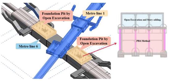
Figure 1.
Location of open excavation foundation pit of Pingguo Yuan Station.
2.2. Geological and Hydrological Conditions of Construction
According to the survey data obtained from the construction site, the soil layer within the story-adding section created by open excavation comprised silty clay, pebble ②, pebble ⑤, pebble ⑦, pebble ⑨, pebble ⑪, and sandstone, as shown in Figure 2. There was a layer of phreatic water within the station, with a level of 39.76 m and a water level elevation of 31.58 m. The groundwater level was approximately 10.4 m below the station bottom plate. Groundwater has little effect on station construction; therefore, it was not considered.
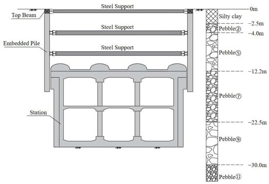
Figure 2.
Soil layer distribution of transfer hall by open excavation in Pingguo Yuan Station.
2.3. Open Excavation and Added-Stories Construction
The transfer hall created by open excavation was located above the underground excavation structure of the three-story section of the Pingguo Yuan Station. The foundation pit was divided into two independent foundation pits located on the east and west sides of Pingguo Yuan Station. The plan view size of the two foundation pits was the same, with a length of 39.8 m, width of 26.9 m, and depth of 12.2 m. The foundation pit was supported by piles and internal supports. The supporting piles were Φ1000 manual digging piles with a pile spacing of 1.6 m and was supported by 100 mm thick hang net shotcretes. The foundation pit was vertically held with three supports: the corner of the first one was concrete support, the middle was steel support, and the second and third were supported by steel pipes with a diameter of 0.8 m and a wall thickness of 16 mm. Because of the existing station structure under the foundation pit, the supporting piles on the east and west sides could not be embedded into the soil and were in the form of end-suspended piles. The supporting piles on the north and south sides of the foundation pit were embedded in the soil near the existing station in the form of embedded piles.
The foundation pit of the added story above the existing station adopted open excavation. First, a supporting pile for the foundation pit was constructed. After the end-suspended pile on the east and west sides of the foundation pit is excavated for adding a story above the existing station, the primary support concrete of the existing station should be chiseled out and the reinforcement at the bottom of the pile should be connected to the primary support geogrid of the existing station. Subsequently, a foundation pit should be constructed before constructing the pile top beam. The first support should be erected when the excavation depth is 0.5 m. Soil excavation should be continued to erect the second and third steel supports. When excavating soil below the third support, an earth berm should be reserved at the four corners of the foundation pit. the remaining soil should be excavated. Parts of the primary support structure and plain concrete of the existing station that affect the construction should be broken; subsequently, a waterproof layer and sidewall structure should be constructed. The reserved earth berm soil should be excavated after the sidewall structure reaches the desired strength. After the sidewall structure of the main body reaches the desired strength, the third steel support should be removed first, and then the second steel support should be removed. Finally, the main body structure of the remaining transfer hall should be constructed. After the top plate construction meets the strength requirements, the remaining supports and top beams should be removed. The supporting pile should be broken 3 m below the ground. The foundation pit construction will be complete after backfilling.
3. Numerical Simulation of Open Excavation and Added-Stories Construction
The open excavation of the foundation pit above the existing station significantly affects the station and foundation pit. Therefore, a finite element model was established to quantitatively analyze this effect using a numerical simulation.
3.1. Calculation Model
Considering that the retaining structure of the foundation pit has a certain effect range on the outer soil [22,23], the model size in this study was determined to be 108 m × 120 m × 55 m by measuring 3.3 H horizontally out of the pit (H is the excavation depth) and 2 H vertically down from the bottom of the station. The finite element model is presented in Figure 3. Constraints were set around the model and on the ground, except for the upper surface of the model, without considering seepage. Model details are depicted in Figure 4.
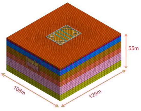
Figure 3.
Finite element model.
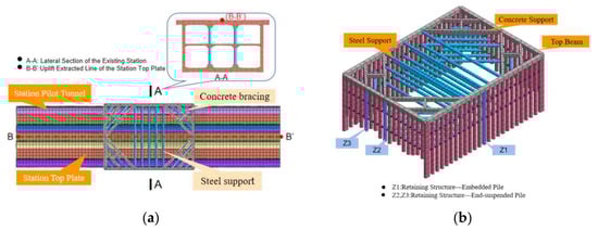
Figure 4.
Schematic diagram of retaining structure and existing station. (a) Top view of existing station; (b) schematic diagram of retaining structure.
A 1D truss element was used to simulate the steel support of the model. The supporting pile, top beam, steel pipe pile, and concrete support were simulated using a 1D beam element, and a 3D element was used to simulate the soil and lower existing station. The formation parameters were modified according to the geological survey data. The primary parameters required by the model are listed in Table 1 and Table 2. The specific simulation steps include the construction using the PBA method on the lower station, construction of the retaining structure, construction of the top beam and first support, excavation to 0.5 m (−4 m) below the second support, construction of I-steel purlin and second steel support, excavation to 0.5 m (−8.7 m) below the third support, construction of I-steel purlin and third steel support, and excavation to the top of the existing station (−12.2 m). An activated or passivated grid was used to simulate the excavation and support construction. The primary support and grouting construction were simulated by adding and modifying the boundary conditions of the element attributes during the construction stage.

Table 1.
Mechanical parameters of soil.
Table 2.
Model parameters.
3.2. Deformation of Existing Stations and Forced Action on Them
The maximum displacement of the existing station in the lower region was closely related to the depth of the foundation pit created by open excavation. The deformation of an existing station under large unloading becomes complex. Therefore, to determine the deformation law of the existing station and ensure its safety, it is necessary to analyze the effect of open excavation and story-adding on the station below the foundation pit.
A cloud diagram of the overall vertical displacement of the existing station was extracted, as shown in Figure 5a. Observe that the station exhibits obvious uplift deformation near the foundation pit. The uplift value in each excavation stage of the station top plate on line B-B’ in the model was extracted and drawn in curves, as shown in Figure 5b. With an increase in the upper foundation pit depth, the uplift in the station top plate gradually increased. The uplift in the station top plate is within the longitudinal uplift range of the station top plate in the excavation area and 30 m area on both sides of the foundation pit.
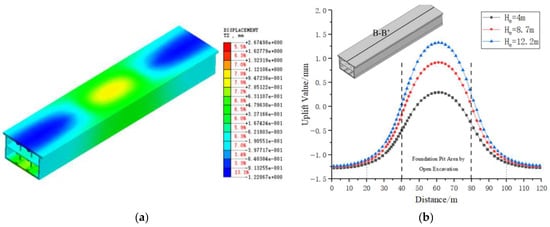
Figure 5.
Schematic diagram of longitudinal uplift of station. (a) Comparison of uplift on top plate B-B’ line; (b) comparison of uplift on top plate B-B’ line.
The vertical and horizontal displacement cloud diagrams of section A-A’ of the existing station before and after foundation pit excavation were extracted by simulation, as shown in Figure 6. Observe from Figure 6a,b that the station top and bottom plates deformed toward the inside of the station before excavation. After excavating the foundation pit above the existing station, the existing station top and bottom plates were uplifted to different degrees, with maximum uplift values of 2.61 and 1.35 mm, respectively. The total uplift of the top plate is greater than that of the bottom plate. Figure 6c,d depict the horizontal displacement of the existing station. Observe from the figure that the horizontal displacement of the sidewall of the station was small; moreover, the sidewall of the station moved horizontally to the soil side before excavation. After excavating the foundation pit, the sidewall showed a tendency of internal crowding. The maximum horizontal displacement of the sidewalls before and after excavation was 0.51 mm.
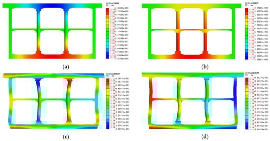
Figure 6.
Displacement cloud diagram of section A-A of existing station before and after excavation. (a) Vertical displacement before excavation; (b) vertical displacement after excavation; (c) horizontal displacement before excavation (enlarged by five times); (d) horizontal displacement after excavation (enlarged by five times).
A comparison cloud diagram for the vertical and horizontal stresses in section A-A’ before and after the foundation pit excavation was extracted is shown in Figure 7. Notice that after the foundation pit excavation, the stress state of the station top plate changes from the upper compression and lower tension states to the upper tension and lower compression states, respectively. The stress state of the station bottom plate before excavation is that the lower part is compressed and the upper part is tensioned, whereas the stress state of the station bottom plate after excavation remains unchanged but the stress value decreases. After foundation pit excavation, the stress state of the upper sidewall changes from external tension and internal compression to external compression and internal tension, respectively. The change in the horizontal load on the lower sidewall was small; although the stress state remained unchanged, the stress value decreased. The maximum tensile stress of the station structure before and after excavation was 1.28 MPa; the station was not damaged.
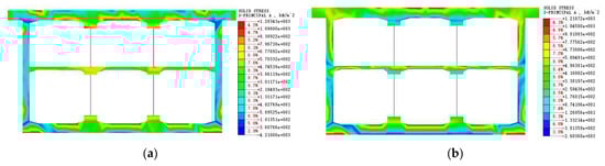
Figure 7.
Cloud diagram of section A-A stress of existing station before and after excavation. (a) Cloud diagram of stress before excavation; (b) cloud diagram of stress after excavation.
The analysis demonstrated that the vertical load at the top of the station disappeared after foundation pit excavation. Under the lateral and bottom loads, the overall uplift of the station remains within the pit range and direction of the bending moment of the station bottom plate changes; accordingly, the stress state changes. The overall uplift of the station reduces the bending moment of the station bottom plate, which alleviates the stress of the station bottom plate.
A comparison diagram for the effective plastic strain in section A-A’ of the existing station before and after excavation was extracted. Figure 8a,b show that after excavation construction, the surrounding rock is partially broken on both sides of the station, and the plastic zone is further expanded owing to the upper excavation. The surrounding rock develops from a pit angle of 45° upward to the surface fracture surface, whereas the plastic zone on both sides of the station continues to extend upward. The two stages of the plastic zone are connected, forming a fracture surface extending from both sides of the station to the surface. Observe that the plastic zone of the surrounding rock is enlarged after foundation pit excavation, and the horizontal load of the station is increased, which leads to an internal extrusion trend in the sidewall of the structure.
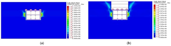
Figure 8.
Comparison diagram of effective plastic strain before and after excavation: (a) before excavation; (b) after excavation.
3.3. Deformation of the Retaining Structure
For the existing station, part of the foundation pit supporting piles are end-suspended piles on the top of the station, and part of those are embedded piles of the adjacent station. The horizontal displacements of the embedded piles and end-suspended piles were analyzed via numerical simulation to explore the deformation mode of the retaining structure affected by the existing structure.
Pile Z1 was a longitudinal midspan embedded pile in the foundation pit. Figure 9a shows the horizontal displacement curve during the excavation of pile Z1. As shown in the figure, the overall deformation of the embedded pile causes bulging in the medium and there is no significant change in the horizontal displacement of the top of the embedded pile under the three-step excavation, indicating that the first steel and concrete supports are effective. When the excavation depths are 4, 8.7, and 12.2 m, the maximum horizontal displacements are 1.06, 2.14, and 2.67 mm, respectively. Accordingly, the maximum horizontal displacements at excavation depths of 4 and 8.7 m increase significantly, and the embedded pile descends to the pit bottom at the maximum displacement. Therefore, monitoring and measurement are necessary during the third excavation stage to ensure the stability of embedded piles.
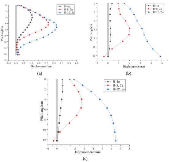
Figure 9.
Horizontal displacement curve of supporting pile. (a) Horizontal displacement curve of pile Z1; (b) horizontal displacement curve of pile Z2; (c) horizontal displacement curve of pile Z3.
Pile Z2 was a horizontal midspan end-suspended pile in the foundation pit. Figure 9b shows the horizontal displacement curve during the excavation of pile Z2, which indicates that the horizontal displacement of the bottom pile can be controlled when the excavation reaches 4 and 8.7 m. When the excavation reaches 8.7 m, the maximum horizontal displacement occurred in the upper part of the pit bottom, and horizontal displacement occurred at the pile bottom. The unexcavated soil at the pit bottom poses certain restrictions on the horizontal displacement of the bottom of pile Z2. When the excavation depth reaches 12.2 m, no soil was embedded in the bottom of the end-suspended pile, which led to a displacement of the pile bottom toward the inner side of the foundation pit, with a maximum horizontal displacement of 4.85 mm. Figure 9c shows a comparison curve for the horizontal displacement during the excavation of pile Z3. Pile Z3 was an end-suspended pile horizontally located at 1/4 of the foundation pit. Unlike pile Z2, pile Z3 was located between two steel diagonal braces. Observe from the figure that when the excavation depth reached 8.7 m, the maximum horizontal displacement of the pile was 2.72 mm. When excavation depth reached the pit bottom, the horizontal displacement of the pile bottom was 6.48 mm. Based on the horizontal displacement of the end-suspended piles Z2 and Z3, we found that the steel diagonal brace restricted the horizontal displacement of the middle and upper ends of the end-suspended pile; however, the displacement of the pile bottom was not effectively controlled, evident by the existing slip deformation. The horizontal displacement of the end-suspended pile bottom between the two diagonal steel braces was significant. Therefore, necessary security controls need to be implemented.
4. Safety Control Measures for End-Suspended Piles
4.1. Influence of Different Control Measures on Pile Deformation
The analysis indicated a large slip deformation at the bottom of the end-suspended pile. Three control measures can be used improve the pile deformation: strengthening the primary support between the pile bottom and station top plate structure connected to the bottom of the embedded piles, constructing a grouting reinforcement after the pile to increase the bearing capacity of the soil behind the pile, and reserving the earth berm at the pit bottom to increase the soil in the passive area. Accordingly, the simulation conditions were changed numerically. The effects of the three control measures on the end-suspended pile are discussed to determine the control effect of each measure on the displacement of the end-suspended pile.
4.1.1. Influence of Pile Bottom Fixation
The connection to the pile bottom combined with the primary support geogrid with the main reinforcement of the end-suspended pile results in pile bottom embedding. Figure 10 shows the horizontal displacement comparison curve of the end-suspended piles Z2 and Z3 after being connected to the pile bottom, which shows that the connection to the pile bottom has no obvious control effect on the pile displacement when the excavation depth reaches 4 m. The maximum horizontal displacement of pile Z2 was reduced to 1.01 mm when the excavation depth reached 8.7 m, signifying a decrease of approximately 49%, whereas that of pile Z3 was reduced to 1.82 mm, signifying a decrease of approximately 33%. When the excavation depth reaches 12.2 m, the bottom displacements of piles Z2 and Z3 can be controlled. Observe that after establishing the pile bottom connection, the pile deformation causes a more stable bulging in the medium. The pile bottom of the end-suspended pile is embedded, which makes the controlling effect of the pile bottom slip significant, while significantly reducing the pile displacement.
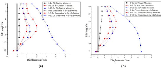
Figure 10.
Comparison curve before and after connection to pile bottom: (a) pile Z2; (b) pile Z3.
4.1.2. Influence of Formation Grouting Reinforcement
When the excavation depth of the foundation pit was less than 4 m, the horizontal displacement of the end-suspended pile was small. Therefore, the soil behind the end-suspended pile was reinforced by grouting from 3.7 m below the ground with respect to the station top. The grouting reinforcement position is shown in Figure 11, where Ln denotes the grouting reinforcement thickness. By studying the effects of different grouting reinforcement thicknesses on the end-suspended pile, the best grouting reinforcement thickness was selected as Ln = 1–6 m.
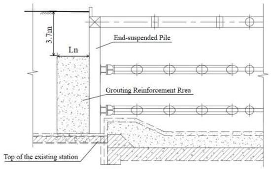
Figure 11.
Schematic diagram of grouting reinforcement position.
Moreover, when the excavation depth was less than 4 m, the displacement of the pile was small. Accordingly, the horizontal displacement curves of the end-suspended pile under different grouting reinforcement thicknesses at excavation depths of 8.7 and 12.2 m are extracted as shown in Figure 12 and Figure 13. The figures show that the horizontal displacement of the pile gradually decreased with an increase in the grouting reinforcement thickness. When the reinforcement thickness was greater than 3 m, the control effect of the horizontal displacement on piles Z2 and Z3 decreased significantly. Based on a comprehensive analysis, the best grouting reinforcement thickness was determined as 3 m. When H = 8.7 m and the grouting reinforcement thickness is 3 m, the maximum decrease in pile Z2 is approximately 46% and the maximum decrease in pile Z3 is approximately 41%. When H = 12.2 m and the grouting reinforcement thickness is 3 m, the horizontal displacement of the bottom of pile Z2 is 1.42 mm, signifying a decrease of approximately 71%. whereas that of the bottom of pile Z3 is 1.76 mm, signifying a decrease of approximately 73%. The maximum horizontal displacement occurred in the piles. After grouting reinforcement, the pile displacement was significantly improved. Notice that reinforcing the grouting after the pile is constructed can improve the mechanical parameters of the soil, increase the bearing capacity of the soil behind the pile, and improve the anti-deformation capacity of the area behind the pile, which improves the ultimate bearing capacity of the end-suspended pile. Although reinforcing the grouting after the pile was constructed improved the displacement of the pile, there remained a risk of slipping at the bottom of the end-suspended pile when excavation depth reached the bottom of the pit. Therefore, a connection to the pile bottom was necessary to achieve the best control effect.
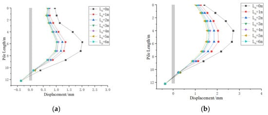
Figure 12.
Comparison curve of thickness effect of grouting reinforcement with H = 8.7 m: (a) pile Z2; (b) pile Z3.
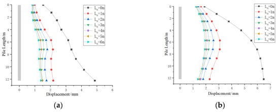
Figure 13.
Comparison curve of thickness effect of grouting reinforcement with H = 12.2 m: (a) pile Z2; (b) pile Z3.
4.1.3. Influence of Excavation Earth Berm
The reserved earth berm comprised undisturbed soil at the four corners of the foundation pit. In the calculation, the range of counter pressure soil is 8 m long in the longitudinal direction, 2 m high along the foundation pit, and 6 m wide in the transverse direction. Figure 14 shows a comparison curve of the horizontal displacement of piles Z2 and Z3 after reserving the earth berm, which indicates that the overall horizontal displacement of pile Z2 decreased but slip deformation still occurred at the pile bottom. The displacement at the bottom of pile Z3 was improved. In other words, it decreased from 6.47 to 3.73 mm, signifying a decrease of approximately 42%, which has less effect than the connection to the pile bottom and grouting reinforcement measures and can be used as an auxiliary measure to ensure the safety of the retaining structure.
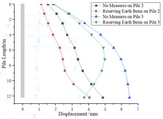
Figure 14.
Comparison curve of horizontal displacement of end-suspended pile with H = 12.2 m.
4.2. Development of Safety Control Measures
After analyzing the effect of several stabilizing control measures on the end-suspended pile, we determined that all three control measures play a positive role in stabilizing the end-suspended pile. A combination of the three control measures is required to strengthen the end-suspended piles during the construction.
4.2.1. Connection Technology between Pile Bottom and Existing Primary Support Structure
When the end-suspended pile excavation reaches to the pilot tunnel top of the existing station, the air pick breaks the primary support structure of the existing station until the geogrid is exposed. Subsequently, the main reinforcement at the pile bottom is connected to the primary support geogrid. The primary support geogrid is connected to the main reinforcement of the end-suspended pile to effectively embed the pile bottom. The pile bottom connection in the pilot tunnel of the station is shown in Figure 15.
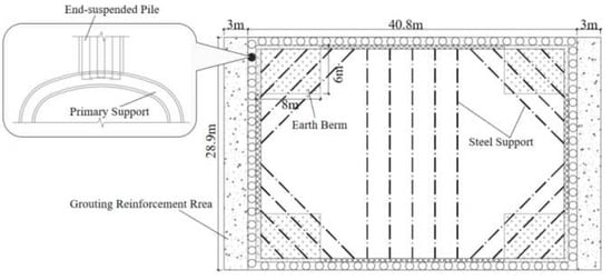
Figure 15.
Schematic diagram of safety reinforcement measures.
4.2.2. Deep Hole Grouting Reinforcement after Pile Constructed
After the end-suspended pile is constructed, the soil between the piles is grouting-reinforced, with a grouting width of 3 m. The grouting area extends from 3.7 m below the earth’s surface to the bottom of the foundation pit to improve the ultimate bearing capacity of the end-suspended pile. The grouting reinforcement positions are shown in Figure 15.
4.2.3. Reserving Earth Berm at the Pit Bottom
When the excavation depth reached below the third support, the undisturbed soil at four corners of the foundation pit should be retained to achieve a counter-pressure in the foundation bottom. The earth berm should be 8 m long in the longitudinal direction, 2 m high along the foundation pit, and 6 m wide in the transverse direction. The position of the earth berm is shown in Figure 15. The earth berm should be excavated after constructing the sidewall structure of the first formwork outside the earth berm range.
Using finite element simulation, the three safety reinforcement measures were comprehensively applied to the foundation pit excavation working conditions. Subsequently, the horizontal displacement of piles Z2 and Z3 after safety reinforcement was measured to construct a comparison curve of the horizontal displacement without safety measures and that with the three comprehensive measures, as shown in Figure 16. Observe that under the several comprehensive safety measures, the overall horizontal displacement of the end-suspended pile has been significantly reduced, pile bottom slip has been significantly controlled, and maximum horizontal displacement of piles Z2 and Z3 has been controlled within 1.5 mm, all of which effectively ensure the stability of the retaining structure. The vertical displacement along the B-B’ line on the top plate of the station with or without safety measures is extracted to construct the comparison curve of the station vertical displacement, as shown in Figure 17. Observe from the figure that the three safety control measures have little influence on the roof uplift of the station; in addition, the uplift of the grouting reinforcement area and that for the area where the foundation pit is located are alleviated.
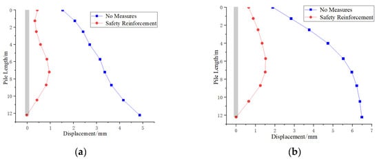
Figure 16.
Comparison curve of safety reinforcement of end-suspended pile: (a) pile Z2; (b) pile Z3.
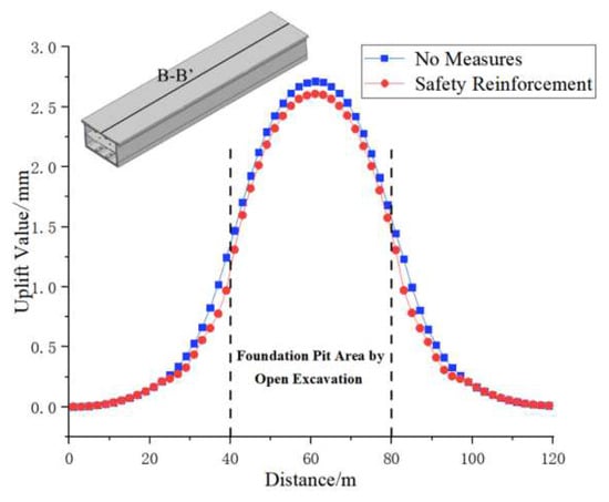
Figure 17.
Longitudinal uplift contrast curves of existing stations.
5. Field Test
5.1. Experimental Scheme
The existing station is located in the strong-effect area of the open excavation foundation pit. During the construction of the open excavation foundation pit, the existing station and retaining structure can be monitored to ensure stability. A set of section monitoring items was located every 5–10 m along the longitudinal direction of the existing station. Four pile deformation measurement points were set midway between the short side of the foundation pit and external corner of the foundation pit to monitor the entire pile length. The layout of each measurement point is shown in Figure 18.
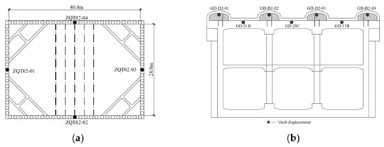
Figure 18.
Layout of measuring points. (a) Measuring points of foundation pit retaining structure; (b) section survey points of existing stations at section A-A.
5.2. Deformation of Foundation Pit Retaining Structure
Figure 19 shows a comparison diagram regarding the horizontal displacement of the midspan embedded pile and midspan end-suspended pile. The simulated value denotes the horizontal displacement of the pile after reinforcement. Figure 19a depicts that the deformation mode of the embedded pile had a medium drum shape. When excavation depth reaches the pit bottom, the maximum horizontal displacement of the pile becomes 2.31 mm. The pile bottom is close to the existing station, the horizontal displacement at the pile bottom varies little, and the maximum horizontal displacement becomes 8.7 m, which indicates that the third steel support after prestress plays a role in controlling the deformation of the pile. As shown in Figure 19b, after the control measures for the end-suspended pile are implemented, the deformation mode of the pile is similar to that of the embedded pile; the pile bottom slip is effectively controlled. When the excavation depth reached the pit bottom, the maximum displacement of the pile body was only 0.95 mm; accordingly, the stability of the retaining structure was guaranteed.
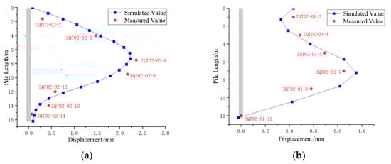
Figure 19.
Comparison diagram of horizontal displacement of measuring points: (a) ZQT02-02; (b) ZQT02-01.
5.3. Deformation of the Existing Station
The measured value presented in Figure 20 is the arch crown monitoring data along section A-A’, whereas the simulated value signifies the total uplift value of the station top plate of section A-A’ after the control measures are implemented. The comparison indicates that the control measures have little effect on the uplift value of the station top plate, and the station’s maximum uplift value occurs at the midspan. The simulated value is consistent with the measured value in terms of the size and change trend. The measured maximum uplift value of the station is 2.41 mm.
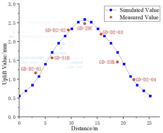
Figure 20.
Comparison diagram of uplift value of station top plate.
The abovementioned measurement results are similar to the numerical simulation results, which indicates that the numerical simulation is reasonable, and the optimization and reinforcement of the open excavation and story-adding of the foundation pit based on numerical simulation are effective.
6. Conclusions
For the open excavation and story-adding project at the Pingguo Yuan Station of Beijing metro line 6, the existing station and retaining structure of the foundation pit created by open excavation were analyzed using finite element simulation. Subsequently, the effects of three stabilizing measures were verified based on field measurements. Accordingly, the following conclusions are drawn:
- (1)
- After unloading the soil above the station, the vertical load at the top disappeared. Under lateral and bottom loads acting on the station, the overall station uplift in the foundation pit area changed from subsidence to uplift, and the uplift value of the roof reached 2.59 mm. The sidewall exhibited an internal crowding trend, and the stress state of the station top plate changed to upper tension and lower compression. The stress state of the upper sidewall is changed to outside compression. In addition, the inside tension state and the stresses on the station bottom plate and lower sidewall are relieved.
- (2)
- After the construction of the station, the surrounding rock is partially broken on both sides of the station. Accordingly, the plastic zone is further expanded owing to the foundation pit excavation, which is simultaneously connected to the underground excavation fracture surface. This enlarges the plastic zone of the surrounding rock, leading to an increase in the horizontal load acting on the station, which then leads to an internal extrusion trend within the structure.
- (3)
- Under the existing structure, the horizontal displacement of the embedded pile can be well controlled; however, the bottom of the end-suspended pile exhibits an obvious slip. The effects of connecting the pile bottom and primary support of the existing station, establishing grouting reinforcement after pile construction, and reserving earth berm on the horizontal displacement of the end-suspended pile are discussed through numerical simulation. Subsequently, we concluded that after establishing the connection between the pile bottom and primary support of the existing station, the slip of the pile bottom was significantly reduced, and the piles bulged in the middle with stability. After grouting reinforcement, the horizontal displacement of the pile decreased by 60%, and the slip of the pile bottom persisted. Reserving the earth berm has a certain controlling effect on the pile bottom slip of the end-suspended pile at the pit corner.
- (4)
- Based on finite element simulation, combined with the measured analysis, after establishing three safety reinforcement measures, the maximum horizontal displacement of the end-suspended pile was controlled to within 1.5 mm. Moreover, the pile bottom hardly slipped, and the stability of the retaining structure was significantly improved, all of which can provide guidelines for similar constructions.
Author Contributions
Conceptualization, J.W. and S.W.; methodology, H.L.; software, H.L.; validation, E.L., Z.W., and S.W.; formal analysis, S.W. and H.L.; investigation, S.W.; resources, E.L.; data curation, H.L.; writing—original draft preparation, H.L.; writing—review and editing, J.W. and S.W.; visualization, S.W.; supervision, S.W.; project administration, E.L.; funding acquisition, J.W. and Z.W. All authors have read and agreed to the published version of the manuscript.
Funding
This research was funded by the Shandong Provincial Key R&D Program (Major Scientific and Technological Innovation Project) Project, grant number 2019JZZY010428, the Postdoctoral Innovation Project of Shandong Province, grant number 202003080, the Natural Science Foundation of Shandong Province, grant number ZR2020QE265 and China Railway Construction Corporation Limited’s 2020 annual scientific research plan, grant number 2020-B05.
Institutional Review Board Statement
Not applicable.
Informed Consent Statement
Not applicable.
Data Availability Statement
The data are contained within the article.
Acknowledgments
We are grateful to the China Railway Fourteenth Bureau Group Co., Ltd., for providing us with the experimental platform.
Conflicts of Interest
The authors declare no conflict of interest.
References
- Ye, S.H.; Zhao, Z.F.; Wang, D.Q. Deformation analysis and safety assessment of existing metro tunnels affected by excavation of a foundation pit. Undergr. Space 2020, 6, 421–431. [Google Scholar] [CrossRef]
- Huang, F.; Zhang, M.; Wang, F.; Ling, T.H.; Yang, X.L. The failure mechanism of surrounding rock around an existing shield tunnel induced by an adjacent excavation. Comput. Geotech. 2019, 117, 103236. [Google Scholar] [CrossRef]
- Chen, R.P.; Meng, F.Y.; Li, Z.C.; Ye, Y.H.; Ye, J.N. Investigation of response of metro tunnels due to adjacent large excavation and protective measures in soft soils. Tunn. Undergr. Space Technol. 2016, 58, 224–225. [Google Scholar] [CrossRef]
- Zhang, X.H.; Wei, G.; Jiang, C.W. The Study for Longitudinal Deformation of Adjacent Shield Tunnel Due to Foundation Pit Excavation with Consideration of the Retaining Structure Deformation. Symmetry 2020, 12, 2103. [Google Scholar] [CrossRef]
- Qiu, J.T.; Jiang, J.; Zhou, X.J.; Zhang, Y.F.; Pan, Y.D. Analytical solution for evaluating deformation response of existing metro tunnel due to excavation of adjacent foundation pit. J. Cent. South Univ. 2021, 28, 1888–1900. [Google Scholar] [CrossRef]
- Zhang, J.; Xie, R.; Zhang, H. Mechanical response analysis of the buried pipeline due to adjacent foundation pit excavation. Tunn. Undergr. Space Technol. 2018, 78, 135–145. [Google Scholar] [CrossRef]
- Zhang, X.M.; Yang, J.S.; Zhang, Y.X.; Gao, Y.F. Cause investigation of damages in existing building adjacent to foundation pit in construction. Eng. Fail. Anal. 2017, 83, 117–124. [Google Scholar] [CrossRef]
- Oztoprak, S.; Cinicioglu, S.F.; Oztorun, N.K.; Alhan, C. Impact of neighbouring deep excavation on high-rise sun plaza building and its surrounding. Eng. Fail. Anal. 2020, 111, 104495. [Google Scholar] [CrossRef]
- Akhtarpour, A.; Mortezaee, M. Dynamic response of a tall building next to deep excavation considering soil-structure interaction. Asian J. Civ. Eng. 2019, 20, 479–502. [Google Scholar] [CrossRef]
- Li, Z.; Han, M.; Liu, L.L.; Li, Y.Y.; Yan, S.H. Corner and partition wall effects on the settlement of a historical building near a supported subway excavation in soft soil. Comput. Geotech. 2020, 128, 103805. [Google Scholar] [CrossRef]
- Yang, X.; Liu, G.B. Performance of a Large-Scale Metro Interchange Station Excavation in Shanghai Soft Clay. J. Geotech. Geoenviron. Eng. 2017, 143, 05017003. [Google Scholar] [CrossRef]
- Ou, X.F.; Zhang, X.M.; Fu, J.Y.; Zhang, C.; Zhou, X.S.; Feng, H. Cause investigation of large deformation of a deep excavation support system subjected to unsymmetrical surface loading. Eng. Fail. Anal. 2019, 107, 104202. [Google Scholar] [CrossRef]
- Liu, J.W.; Shi, C.H.; Cao, C.Y.; Lei, M.F.; Wang, Z.X. Improved analytical method for pile response due to foundation pit excavation. Comput. Geotech. 2020, 123, 103609. [Google Scholar] [CrossRef]
- Zhou, F.C.; Zhou, P.; Li, J.Y.; Lin, J.Y.; Ge, T.C.; Deng, S.M.; Ren, R.; Wang, Z.J. Deformation characteristics and failure evolution process of the existing metro station under unilateral deep excavation. Eng. Fail. Anal. 2021, 131, 105870. [Google Scholar] [CrossRef]
- Li, M.G.; Wang, J.H.; Chen, J.J.; Zhang, Z.J. Responses of a Newly Built Metro Line Connected to Deep Excavations in Soft Clay. J. Perform. Constr. Facil. 2017, 31, 04017096. [Google Scholar] [CrossRef]
- Li, M.G.; Xiao, X.; Wang, J.H.; Chen, J.J. Numerical study on responses of an existing metro line to staged deep excavations. Tunn. Undergr. Space Technol. 2018, 85, 268–281. [Google Scholar] [CrossRef]
- Guo, P.P.; Gong, X.N.; Wang, Y.X. Displacement and force analyses of braced structure of deep excavation considering unsymmetrical surcharge effect. Comput. Geotech. 2019, 113, 103102. [Google Scholar] [CrossRef]
- Zhang, W.G.; Hou, Z.J.; Goh, A.T.C.; Zhang, R.H. Estimation of strut forces for braced excavation in granular soils from numerical analysis and case histories. Comput. Geotech. 2018, 106, 286–295. [Google Scholar] [CrossRef]
- Luo, Z.; Hu, B.; Wang, Y.W.; Di, H.G. Effect of spatial variability of soft clays on geotechnical design of braced excavations: A case study of Formosa excavation. Comput. Geotech. 2018, 103, 242–253. [Google Scholar] [CrossRef]
- Li, H.J.; Tong, L.Y.; Liu, S.Y. Effect of excavation unloading on p-y curves for laterally loaded piles. Comput. Geotech. 2018, 104, 131–139. [Google Scholar] [CrossRef]
- Wang, K.Y.; Li, W.J.; Sun, H.L.; Pan, X.D.; Diao, H.G.; Hu, B. Lateral Deformation Characteristics and Control Methods of Foundation Pits Subjected to Asymmetric Loads. Symmetry 2021, 13, 476. [Google Scholar] [CrossRef]
- Han, J.; Liu, D.; Guan, Y.; Chen, Y.; Li, T.; Jia, D.; Yan, F.; Jia, P.; Zhao, Y. Study on shear behavior and damage constitutive model of tendon-grout interface. Constr. Build. Mater. 2022, 320, 126–223. [Google Scholar] [CrossRef]
- Wang, J.; Han, J.; Chen, J.; Ding, G.; Feng, G.; Liu, T.; Guo, B. Experimental and numerical study on the dynamic response of a superthick backfill subgrade under high-speed railway loading: A case study of Qianjiang-Zhangjiajie-Changde Railway. J. Constr. Eng. Manag. 2022, 148. [Google Scholar] [CrossRef]
Publisher’s Note: MDPI stays neutral with regard to jurisdictional claims in published maps and institutional affiliations. |
© 2022 by the authors. Licensee MDPI, Basel, Switzerland. This article is an open access article distributed under the terms and conditions of the Creative Commons Attribution (CC BY) license (https://creativecommons.org/licenses/by/4.0/).