Article

Magnetic Skyrmion-Based Spiking Neural Network for Pattern Recognition

School of Integrated Circuit Science and Engineering, Beihang University, Beijing 100191, China
*
Author to whom correspondence should be addressed.
Appl. Sci. 2022, 12(19), 9698; https://doi.org/10.3390/app12199698
Submission received: 25 August 2022 / Revised: 14 September 2022 / Accepted: 22 September 2022 / Published: 27 September 2022
(This article belongs to the Special Issue Advanced Integrated Circuits and Devices)

Abstract

:
Spiking neural network (SNN) has emerged as one of the most powerful brain-inspired computing paradigms in complex pattern recognition tasks that can be enabled by neuromorphic hardware. However, owing to the fundamental architecture mismatch between biological and Boolean logic, CMOS implementation of SNN is energy inefficient. A low-power approach with novel “neuro-mimetic” devices offering a direct mapping to synaptic and neuronal functionalities is still an open area. In this paper, SNN constructed with novel magnetic skyrmion-based leaky-integrate-fire (LIF) spiking neuron and the skyrmionic synapse crossbar is proposed. We perform a systematic device-circuit-architecture co-design for pattern recognition to evaluate the feasibility of our proposal. The simulation results demonstrated that our device has superior lower switching voltage and high energy efficiency, two times lower programming energy efficiency in comparison with CMOS devices. This work paves a novel pathway for low-power hardware design using full-skyrmion SNN architecture, as well as promising avenues for implementing neuromorphic computing schemes.

1. Introduction

The human brains are highly efficient in performing pattern cognitive tasks including image recognition, speech recognition et al., which were thought as the main applications of current artificial intelligence (AI) [1]. Generally speaking, we have been studying spike-based coding schemes and various related learning methods [2], trying to mimic the logic and function of the human brain with AI in the field of neuroscience, which is called spiking neural networks (SNNs). SNNs have important applications in pattern recognition as a result of their outstanding performance over traditional machine learning algorithms. In parallel to such progress, hardware implementation of these SNNs mimicking the information transfer in biological neurons, i.e., via the precise timing of spikes or a sequence of spikes has attracted a lot of attention [3,4,5].
Many researchers try to build silicon semiconductor-based circuits through transistor integration to realize spiking neurons. However, there are energy consumption and area problems that are difficult to solve when implementing SNN with CMOS, hindering further development. This is mainly due to the lack of direct mapping to spike neurons and multiple synaptic memory access. Therefore, emerging nonvolatile devices, such as Ag-Si memristors [6], phase change memories [7], and multilayer spintronic devices [8], have been adopted for SNN functionalities exploration. Magnetic random access memory (MRAM) is a typical representative of spintronic devices [9,10]. Many achievements have been made in recent years [11,12,13,14,15], promoting the application of MRAM in neuromorphic computing.
Among the post-CMOS technologies, magnetic skyrmions have emerged as potential candidates due to their small size, stable structure, and low driving threshold current density [16]. There have been prior proposals for SNN implementation based on skyrmions. For instance, ref. [17] considers a skyrmion-based artificial synapse device for neuromorphic systems, mimicking the process of a biological synapse. Ref. [18] introduced a new artificial neuron model, in which the threshold can be modulated by voltage. In addition, the different behaviors of neurons are realized by many parallel skyrmionic devices. Ref. [19] proposed that skyrmion is a spintronic device for deep learning, which improves energy consumption as a spiking neuron processor. Nevertheless, most of these studies focus on single neural/synaptic device functionality demonstration from a device perspective or simple digit recognition with a relatively small array size from the application perspective. A holistic design of an SNN system based on full-skyrmion-based neural network design for complicated pattern recognition is still an open area.
In this paper, we provide a device-circuit-architecture co-design of all-skyrmion leaky-integrate-fire (LIF) type SNN. We choose the LIF neuron model which has attracted a lot of attention in SNN applications in the past two decades [20]. Much progress has been made in previous work on the study of skyrmion-based LIF neurons in terms of device design and performance evaluation. For example, ref. [21] studied skyrmion dynamics driven by the current in the nanotrack, proposing a new LIF neuron device. Ref. [22] mainly studied the performance of the skyrmion-based LIF neuron dynamics in the nanotrack, focusing on size, velocity, energy, and stability. Based on the above achievements, we present a new method to simulate neurons and their synaptic responses, mainly focusing on the circuit implementation of the whole SNN structure. The research provides a new way to build skyrmion-based SNN for complicated pattern recognition tasks, which paves the way for the practical application of skyrmionics and can be used as an alternative to traditional CMOS-based SNN implementation.

2. Overview

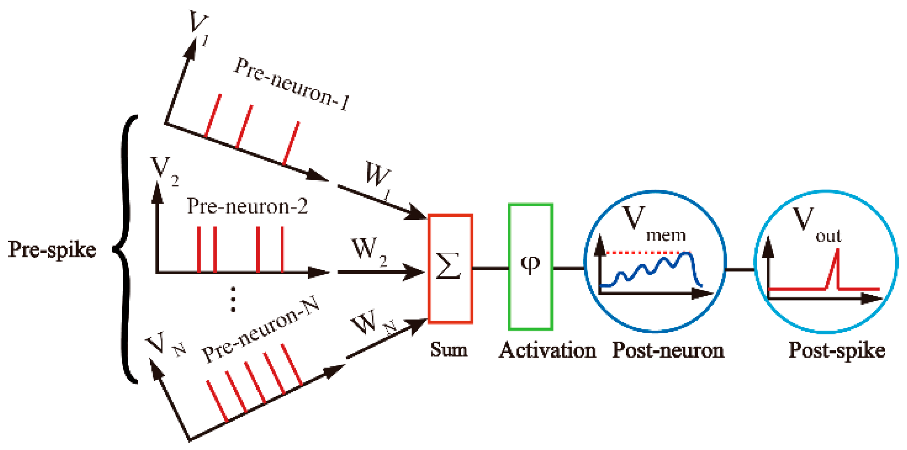
2.1. LIF Neuron Model

A number of spiking models, such as the pulse-coupled IF model [23] and the Spike Response Model [24] have been developed to quantitatively characterize the biophysical neuronal membrane potential and ion channel. As one of the exemplary models, the LIF neuron model has been widely recognized and applied in the field of neuroscience [25]. The principle can be understood by the simplified computational model in Figure 1. The input spikes (Vi) from pre-neurons are modulated by the weights (Wi) which are stored in the interconnecting synapses. The output from all synapses is then summed up and fed to the post-neuron through the non-linear activation function. In response to this weighted current, a neuron’s membrane potential (Vmem) rises by a certain amount but decays slowly to a rest value until the next spike is received. This behavior can be expressed as follows:
            τ m d V m e m d t = ( V m e m V r e s e t ) + i δ ( t t i ) w i
where Vmem is the membrane potential,   V r e s e t is the reset potential, w i is the synaptic weight for the i-th input,     τ m   is the membrane time constant, and δ ( t t i ) is the spiking event occurring at time instant t i . As soon as Vmem crosses a threshold (Vth), the neuron emits a spike, which is transmitted to the next layer of neurons.

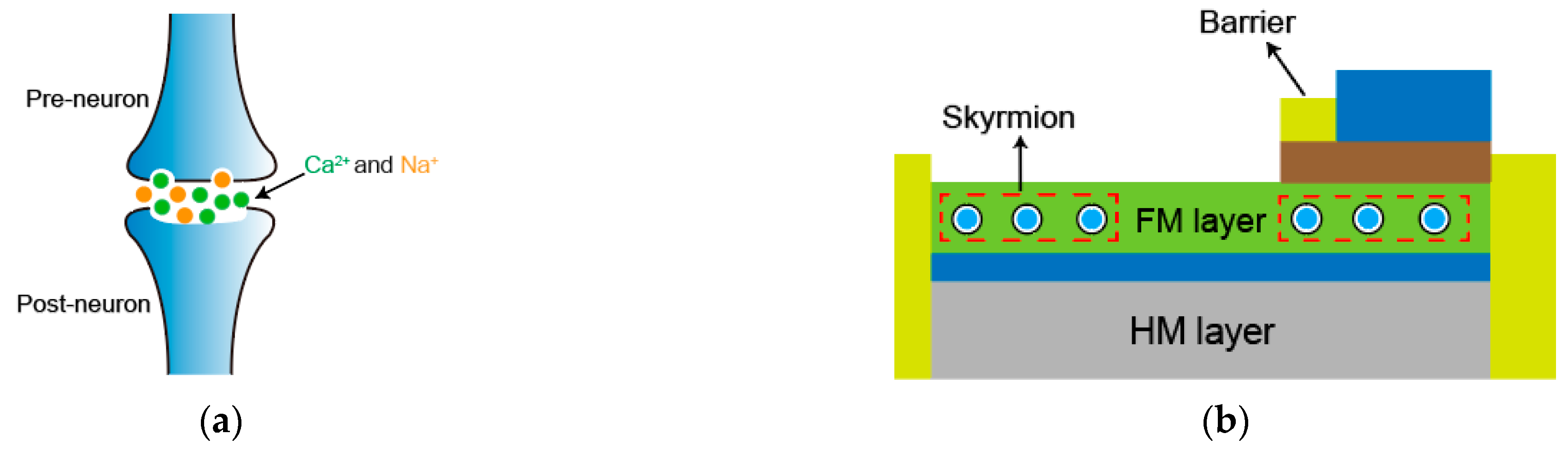
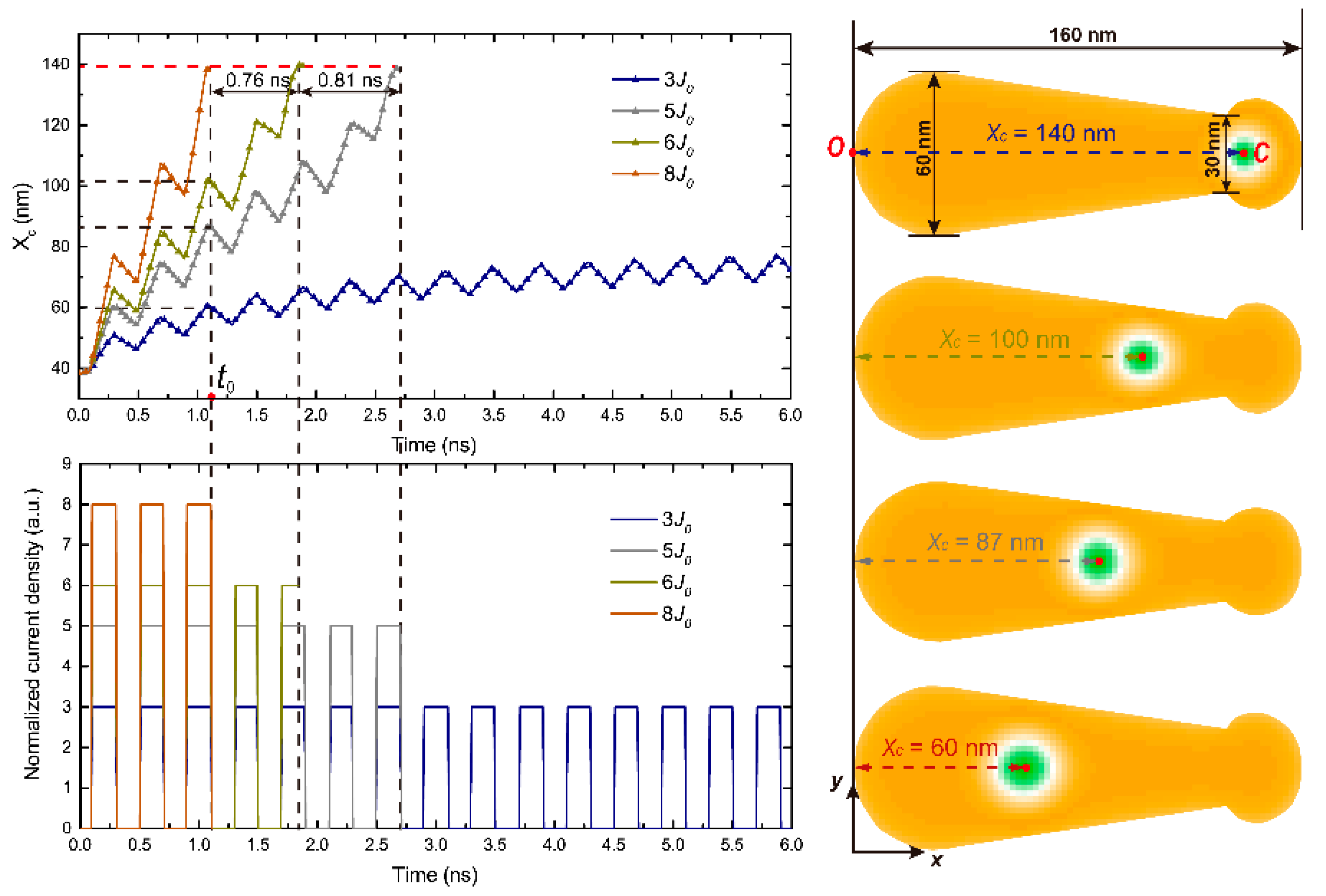
2.2. Skyrmion-Based LIF Neuron

Magnetic skyrmions, topologically protected particle-like spin textures, have been observed in ultrathin magnetic systems with breaking inversion symmetry and large spin–orbital coupling, which can be explained by the presence of the Dzyaloshinskii–Moriya Interaction (DMI) [26]:
H D M = D 1 , 2 · ( S 1 × S 2 )
where HDM is the Hamiltonian parameter, D1,2 is the DMI vector, S1 and S2 are the spins of the two neighboring atoms. Recently, skyrmions in magnetic ultrathin films or multilayer systems have received intensive research interest [27]. To mimic the biological LIF neuron, it is important to represent the membrane potential with an analogy physical quantity concerning the skyrmion motion. According to the previous report [21], the LIF neuronal behavior could be practically described by the skyrmion motion on a pre-designed three-terminal nanotrack device as shown in Figure 2. More practical functionalities of the SNN system, for example, the winner-takes-all module, have also been explored [28].

2.3. Skyrmion-Based Synapse

Analog memory is one of the essential properties of synaptic devices. We may consider using magnetic domain walls (DW) [30] to realize multistage synaptic devices in the field of spintronics. However, DW has the characteristics of random pinning/depinning, at the same time, it requires a relatively high threshold current during movement, which will have a bad impact on the performance of the devices. This does not necessarily follow as skyrmions have particle-like and rigid-body characteristics [26], which allow the number of skyrmions to be increased in a certain area, promising to become a new generation of storage devices [17].
Here we propose a new type of skyrmionic synaptic device composed of a heavy metal (HM, e.g., Pt), a FM layer (e.g., Co), and an energy barrier, as shown in Figure 3b. The skyrmions move on the nanotrack formed by the FM layer and the HM layer, and DMI exists at their interface. The artificial energy barrier divides the nanotrack into pre-synapse and post-synapse areas, which has a higher PMA than FM. Figure 3 illustrates an analogy between the biological synapse (Figure 3a) and the skyrmion-based synapse (Figure 3b). When the received signals (impulses) of pre-neuron reaches a threshold, certain Ca2+ or Na+ channel open, and neurotransmitters are released into the biological synapse region. Then, the post-neuron will change its conductance when the ions are received. Similarly, the skyrmion-based synapse changes its conductance due to the skyrmion generation and migration process when the input stimulus signals are received. Therefore, the electric-current-controlled accumulation and dissipation of skyrmions can imitate the variations of synaptic behavior with the weights proportional to the number of skyrmions.

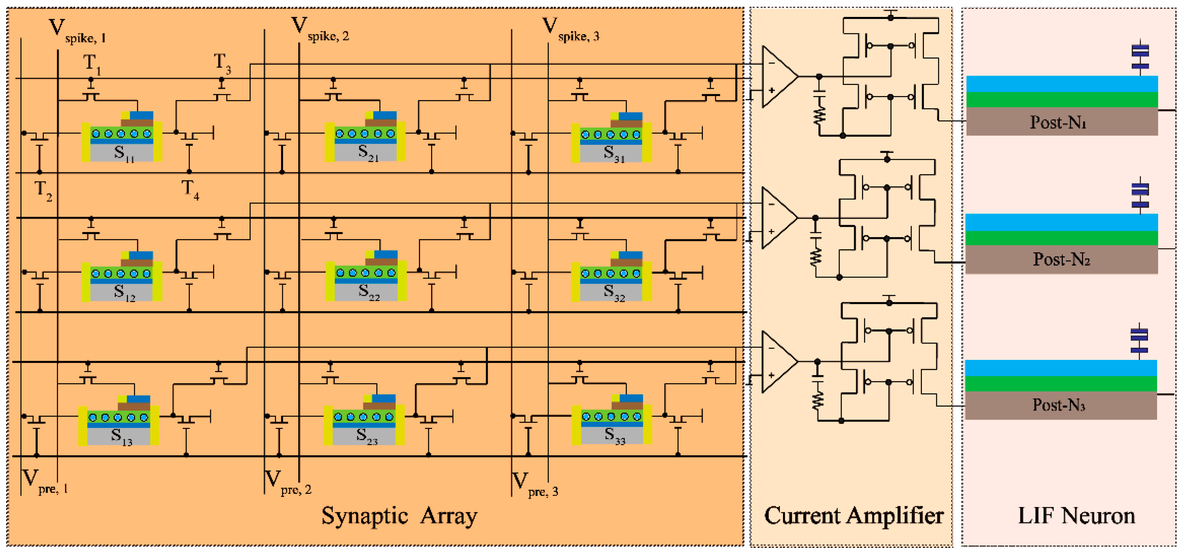
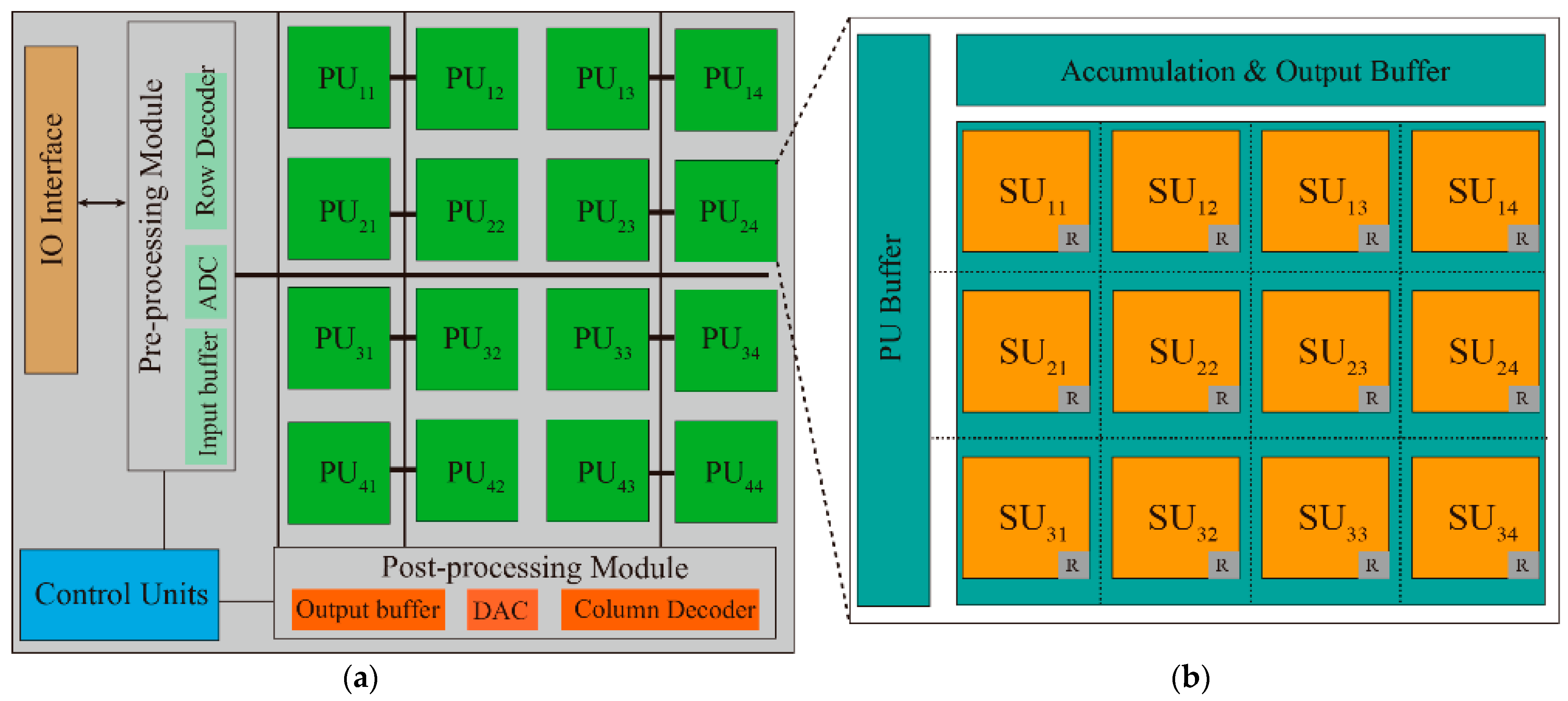
3. Proposed Architecture

All-Skyrmion SNN Architecture
In order to utilize the proposed skyrmionic devices, we construct a full-skyrmion subarray to generate the pattern recognition result. Figure 4 illustrates an example of the proposed full-skyrmion SNN subarray structure (3 × 3), which consists of the skyrmion-based synaptic array to store the synapse weight and the LIF neurons with a current amplifier connection. Herein, there are three pre-neurons (pre-N1, pre-N2 and pre-N3, not shown in the figure) and three post-neurons (post-N1, post-N2 and post-N3). The nine synapses were designed to connect the corresponding pre- and post-neurons through four switch transistors in each cell. For instance, the pre-synapse region of synapse S11 was connected to pre-N1 through transistors T1 and T2 while the post-synapse region was connected to post-N1 through transistors T3 and T4. Thus, the synaptic weight was expressed by the number of skyrmions in S11. The spiking current channel will not be closed until the post-neuron spike or a reset signal. The synaptic weights can modulate the spike voltage Vspike from the pre-neuron, which is then transmitted to the post-neuron via the current amplifier. It should be noted that the synaptic weight is constant during this process. Once the post-neuron spikes, the synaptic device shifts to the learning pattern, and the skyrmions are driven, causing the number of s skyrmions in the post-synapse region to change, as well as the synaptic weights. This designed synaptic array can also map convolutional and fully-connected layers of artificial CNNs and DNNs with spiking neurons and interconnecting synapses.
Based on the subarray structure, we have designed a full-skyrmion SNN engine as shown in Figure 5. Figure 5a shows the top-level skyrmion-based SNN architecture, which contains multiple processing units (PU), IO interface, pre-processing module, post-processing module, and global control units. At this level, the pre-processing module will accomplish the data caching and convert the analog data into a digital domain if necessary. Then the input data will be transferred to each PU to complete the operation with the weights which have been trained offline and mapped into the PU array through an H-tree method. With a group of partitioned PUs, the SNN engine could be able to hold the large network structure for different applications and take multiple input data to generate independent outputs simultaneously. After the operation, the firing spike will be collected by the post-processing module and transferred to the next layer. One should note that Figure 5b shows a PU containing multiple subarray units (SU) with PU buffer and accumulation and output buffer. Within a PU, the routers will receive the input data from the PU buffer, simultaneously making it possible to communicate among SUs and transfer partial sums from SUs to accumulation units.

4. Simulation and Discussion

In order to evaluate the feasibility of the proposed skyrmion SNN for pattern recognition tasks, a systematic device-circuit-architecture simulation was conducted.

4.1. Micromagnetic Simulation

To gain insight into the skyrmion motion and LIF behavior in the nanotrack, we used the OOMMF [31] software to conduct micromagnetic simulations by solving the Landau–Lifshitz–Gilbert (LLG) equation as (3):
d m d t = γ m × h eff + α ( m × d m d t ) γ P j d 2 μ 0 e M s t f [ m × ( m × m p ) ]
Table 1 lists some key parameters in the simulation and shows their values. Gilbert damping α = 0.3 , exchange stiffness A = 15   pJ / m , spin polarization P = 0.4 , saturation magnetization M s = 580   kA / m , and DMI value D = 3   mJ / m 2 . Furthermore, the PMA value of the nanotrack satisfies a linear relationship, i.e., K u ( l x ) = K u 0 + Δ K u l x , in which K u 0 = 0.7   MJ / m 3 , Δ K u is the PMA increasing rate at 7.0 × 10 4   MJ / m 3 · nm , and l x is the relative distance from the nanotrack origin. References [21,22] give a more detailed description of the micromagnetic simulation.
The simulation results with square wave excitations was shown in Figure 6. The amplitude of the current density is referred to as the Idrive with the same frequency (T = 0.4 ns, duty ratio r = 0.5) selected at point O indicated as the red point in the top view of the structure in Figure 6. The skyrmion is initially nucleated at an origin site (Xc ≈ 40 nm) and then moves forward along the nanotrack. Under 8   J 0 , the skyrmion will overcome the repulsive force and move forward, which corresponds to the “integrate” process of the LIF neuron. During the interval of two contiguous excitation signals, the skyrmion will go backward, which corresponds to the “leaky” process of the LIF neuron model. Finally, since 8   J 0 exceeds the skyrmion depinning current density, with the continuous arrival of the excitation signals, the skyrmion will arrive at the detection point C in about three periods and be detected by the read head, which corresponds to the “fire” process. However, as the current intensity decreased from 8   J 0 to 5   J 0 , the time consumed to reach the detecting point increased. The skyrmion in the first track has reached the detecting point C while the other three are at 100 nm, 87 nm, and 60 nm, respectively. Specifically, as the Idrive dropped below 3   J 0 , the skyrmion may never be detected since the driving force and repulse force have reached an equilibrium. The results show that the skyrmion neuron can successfully emulate the LIF function of biological neurons.

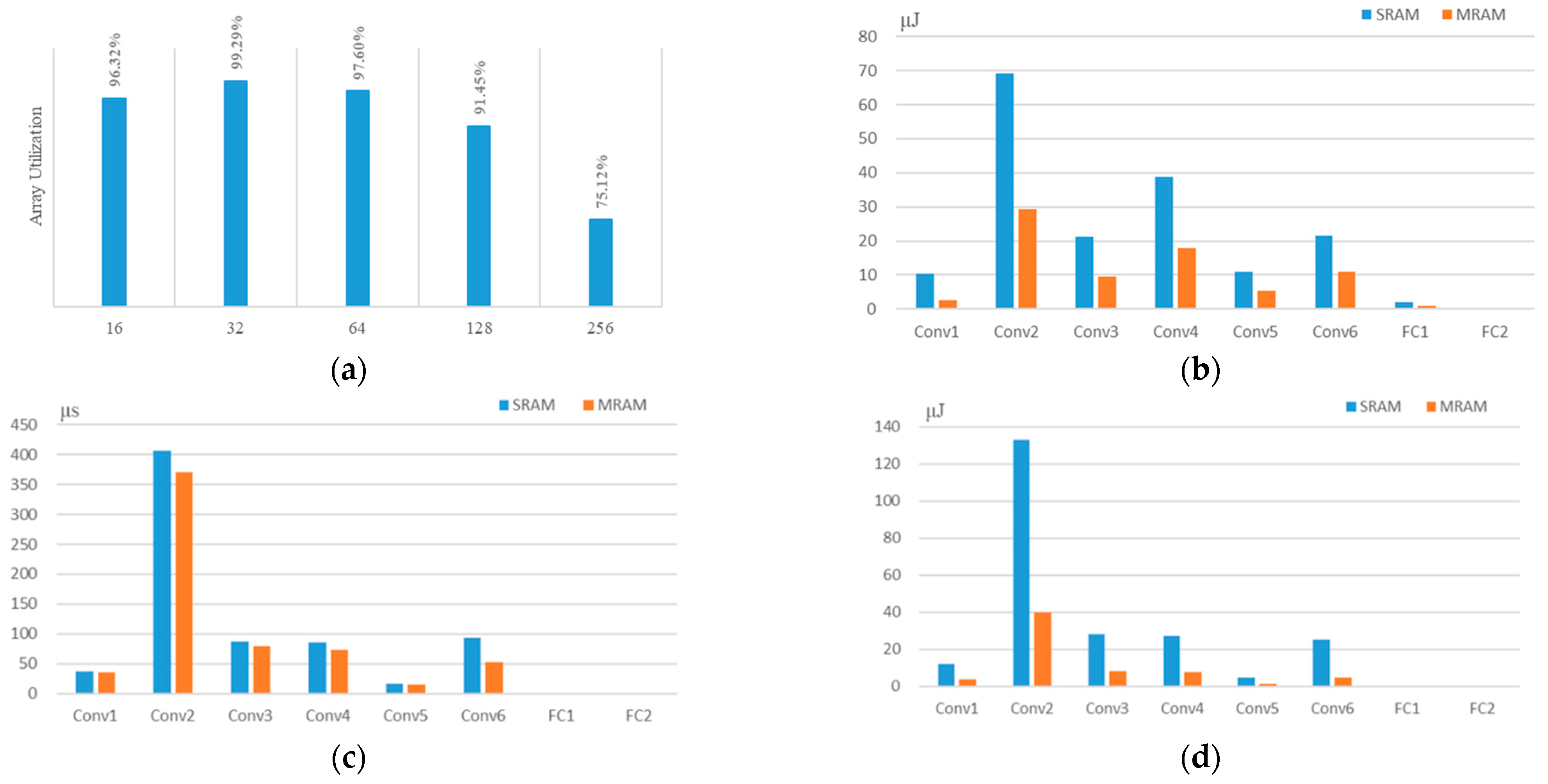
4.2. System Simulation

In this section, we estimated the area, latency, and energy of our deep SNN prototype by deploying 8-layer VGG-8 on CIFAR-10 with 1000 selected images. Based on the device model, we developed a deep SNN hierarchical framework starting from device to array architecture with NeuroSim [32]. If readers are interested in or have doubts about how deep SNNs conduct supervised training, you can refer to [33], which has specific instructions. The pre-trained weights have been configured into the SUs in advance by importing the network structure config file. The detailed comparison with SRAM is shown in Table 2 with numerical results including area, system throughput, computation time, and energy consumption. To maximize the utilization of computing resources, we analyze the detailed utilization of the proposed skyrmion subarray design in Figure 7a. The utilization rate will reach the highest value of 99.29% when the size of SU is 32 × 32. Compared to SRAM, the proposed skyrmion-based implementation is times smaller power. In addition, we also analyze the dynamic energy, latency, and leakage energy distribution on different layers. Results in Figure 7b–d show that Conv-2 consumes the most dynamic energy of 38%, the most latency of 59%, and the most leakage energy of 61% of the total. For the throughput performance, we use TOPS (Tera operations per second) to evaluate all the implementations. For energy efficiency, the skyrmion device achieves 4.33 TOPS/W, 2.85 times better than the SRAM. In area efficiency comparison, the skyrmion device is 2 times better than the CMOS-based implementation.

5. Conclusions

The energy and area overhead in large-scale SNN has motivated the utilization of magnetic skyrmion as promising information carriers to replace the electrons. In this paper, we proposed an all-skyrmion spiking deep neural network architecture to mimic the function of neurons and synapses for pattern recognition tasks. The synaptic weight can be changed by regulating the number of skyrmions with current and micromagnetic simulation to verify the LIF behavior of the proposed skyrmionic neuron. Moreover, we have evaluated the area, delay, and energy of the deep SNN prototype and compared it with SRAM in detail. The results show that our proposed skyrmion-based implementation outperforms SRAM with better energy and area efficiency. The result indicated that ultra-low current switching of skyrmionic devices has the potential for low-power-consumption application, suggesting new possibilities for exploiting it in deep SNN architectures. Although magnetic skyrmions have great application potential, many problems including material limitation and experimental detection must be solved before they can be used in practice. At present, skyrmion-based SNN is still in its infancy. Future research should give full play to the advantages of skyrmions, develop new SNN architectures with higher reliability and lower energy consumption, and find more suitable application scenarios.

Author Contributions

Conceptualization and methodology, B.P. and S.L.; software, W.M.; validation, G.W., K.M., and W.W.; formal analysis, Z.Y.; investigation, T.B.; resources, B.P.; data curation, J.C.; writing—original draft preparation, B.P. and S.L.; writing—review and editing, G.W. and T.B.; visualization, K.M.; supervision, S.L.; project administration, B.P.; funding acquisition, B.P. All authors have read and agreed to the published version of the manuscript.

Funding

This research was funded in part by the Fundamental Research Funds for the Central Universities, part by the National Key Research and Development Program of China (Grant No. 2021YFB3601304, 2021YFB3601300), part by the Beijing Nova Program from Beijing Municipal Science and Technology Commission (No. Z211100002121014, Z201100006820042), and part by the National Natural Science Foundation of China (62001019, 61871008).

Institutional Review Board Statement

Not applicable.

Informed Consent Statement

Not applicable.

Data Availability Statement

Not applicable.

Conflicts of Interest

The authors declare no conflict of interest.

References

  1. Lecun, Y.; Bengio, Y.; Hinton, G. Deep learning. Nature 2015, 521, 436–444. [Google Scholar] [CrossRef]
  2. Merolla, P.A.; Arthur, J.V.; Alvarez-Icaza, R.; Cassidy, A.S.; Sawada, J.; Akopyan, F.; Jackson, B.L.; Imam, N.; Guo, C.; Nakamura, Y.; et al. A million spiking-neuron integrated circuit with a scalable communication network and interface. Science 2014, 345, 668–673. [Google Scholar] [CrossRef]
  3. Markram, H.; Gerstner, W.; Sjöström, P.J. Spike-timing-dependent plasticity: A comprehensive overview. Front. Synaptic Neurosci. 2012, 4, 2. [Google Scholar] [CrossRef]
  4. Wu, X.; Saxena, V.; Zhu, K.; Balagopal, S. A CMOS Spiking Neuron for Brain-Inspired Neural Networks with Resistive Synapses and In-Situ Learning. IEEE Trans. Circ. Syst. Expr. Briefs 2015, 62, 1088–1092. [Google Scholar] [CrossRef]
  5. Seo, J.-S.; Brezzo, B.; Liu, Y.; Parker, B.D.; Esser, S.K.; Montoye, R.K.; Rajendran, B.; Tierno, J.A.; Chang, L.; Modha, D.S.; et al. A 45 nm CMOS neuromorphic chip with a scalable architecture for learning in networks of spiking neurons. In Proceedings of the 2011 IEEE Custom Integrated Circuits Conference (CICC), San Jose, CA, USA, 19–21 September 2011. [Google Scholar]
  6. Jo, S.H.; Chang, T.; Ebong, I.; Bhadviya, B.B.; Mazumder, P.; Lu, W. Nanoscale memristor device as synapse in neuromorphic systems. Nano Lett. 2010, 10, 1297–1301. [Google Scholar] [CrossRef]
  7. Kuzum, D.; Jeyasingh, R.G.D.; Lee, B.; Wong, H.-S.P. Nanoelectronic programmable synapses based on phase change materials for brain-inspired computing. Nano Lett. 2012, 12, 2179–2186. [Google Scholar] [CrossRef]
  8. Grollier, J.; Querlioz, D.; Stiles, M.D. Spintronic nanodevices for bioinspired computing. Proc. IEEE 2016, 104, 2024–2039. [Google Scholar] [CrossRef]
  9. Wang, M.; Cai, W.; Zhu, D.; Wang, Z.; Kan, J.; Zhao, Z.; Cao, K.; Wang, Z.; Zhang, Y.; Zhang, T.; et al. Field-free switching of a perpendicular magnetic tunnel junction through the interplay of spin–orbit and spin-transfer torques. Nat. Electron. 2018, 1, 582–588. [Google Scholar] [CrossRef]
  10. Wang, Z.; Zhou, H.; Wang, M.; Cai, W.; Zhu, D.; Klein, J.O.; Zhao, W. Proposal of Toggle Spin Torques Magnetic RAM for Ultrafast Computing. IEEE Electron Device Lett. 2019, 40, 726–729. [Google Scholar] [CrossRef]
  11. Peng, S.; Zhu, D.; Zhou, J.; Zhang, B.; Cao, A.; Wang, M.; Cai, W.; Cao, K.; Zhao, W. Modulation of heavy metal/ferromagnetic metal interface for high-performance spintronic devices. Adv. Electron. Mater. 2019, 5, 1900134. [Google Scholar] [CrossRef]
  12. Wang, M.; Cai, W.; Cao, K.; Zhou, J.; Wrona, J.; Peng, S.; Yang, H.; Wei, J.; Kang, W.; Zhang, Y.; et al. Current-induced magnetization switching in atom-thick tungsten engineered perpendicular magnetic tunnel junctions with large tunnel magnetoresistance. Nat. Commun. 2018, 9, 1–7. [Google Scholar] [CrossRef] [PubMed]
  13. Wang, Z.; Zhang, L.; Wang, M.; Wang, Z.; Zhu, D.; Zhang, Y.; Zhao, W. High-Density NAND-Like Spin Transfer Torque Memory With Spin Orbit Torque Erase Operation. IEEE Electron Device Lett. 2018, 39, 343–346. [Google Scholar] [CrossRef]
  14. Peng, S.; Zhao, W.; Qiao, J.; Su, L.; Zhou, J.; Yang, H.; Zhang, Q.; Grezes, C.; Amiri, P.K.; Wang, K.L. Giant interfacial perpendicular magnetic anisotropy in MgO/CoFe/capping layer structures. Appl. Phys. Lett. 2017, 110, 072403. [Google Scholar] [CrossRef]
  15. Pan, B.; Wang, G.; Zhang, H.; Kang, W.; Zhao, W. A Mini Tutorial of Processing in Memory: From Principles, Devices to Prototypes. IEEE Trans. Circuits Syst. Express Briefs 2022, 69, 3044–3050. [Google Scholar] [CrossRef]
  16. Fert, A.; Cros, V.; Sampaio, J. Skyrmions on the track. Nat. Nanotechnol. 2013, 8, 152–156. [Google Scholar] [CrossRef]
  17. Huang, Y.; Kang, W.; Zhang, X.; Zhou, Y.; Zhao, W. Magnetic skyrmion-based synaptic devices. Nanotechnology 2017, 28, 08LT02. [Google Scholar] [CrossRef]
  18. He, Z.; Fan, D. A tunable magnetic skyrmion neuron cluster for energy efficient artificial neural network. In Proceedings of the Design, Automation & Test in Europe Conference & Exhibition (DATE), Lausanne, Switzerland, 27–31 March 2017; pp. 350–355. [Google Scholar]
  19. Chen, M.-C.; Sengupta, A.; Roy, K. Magnetic skyrmion as a spintronic deep learning spiking neuron processor. IEEE Trans. Magn. 2018, 54, 1500207. [Google Scholar] [CrossRef]
  20. Das, B.; Schulze, J.; Ganguly, U. Ultra-Low Energy LIF Neuron Using Si NIPIN Diode for Spiking Neural Networks. IEEE Electron Device Lett. 2018, 39, 1832–1835. [Google Scholar] [CrossRef]
  21. Chen, X.; Kang, W.; Zhu, D.; Zhang, X.; Lei, N.; Zhang, Y.; Zhou, Y.; Zhao, W. A Compact Skyrmionic Leaky-integrate-fire Spiking Neuron. Nanoscale 2018, 10, 6139–6146. [Google Scholar] [CrossRef]
  22. Li, S.; Kang, W.; Huang, Y.; Zhang, X.; Zhou, Y.; Zhao, W. Magnetic skyrmion-based artificial neuron device. Nanotechnology 2017, 28, 31LT01. [Google Scholar] [CrossRef]
  23. Stimberg, M.; Goodman, D.F.; Benichoux, V.; Brette, R. Equationoriented specification of neural models for simulations. Front. Neuroinformatics 2014, 8, 6. [Google Scholar] [CrossRef] [PubMed]
  24. Clayton, T.; Cameron, K.; Rae, B.R.; Sabatier, N.; Charbon, E.; Henderson, R.K.; Leng, G.; Murray, A. An Implementation of a Spike-Response Model With Escape Noise Using an Avalanche Diode. IEEE Trans. Biomed. Circuits Syst. 2011, 5, 231–243. [Google Scholar] [CrossRef] [PubMed]
  25. Lapicque, L. Recherches quantitatives sur l’excitation electrique des nerfs traitée comme une polarization. J. Physiol. Pathol. Gen. 1907, 9, 620–635. [Google Scholar]
  26. Rohart, S.; Thiaville, A. Skyrmion Confinement in Ultrathin Film Nanostructures in the Presence of Dzyaloshinskii-Moriya Interaction. Phys. Rev. B 2013, 88, 184422. [Google Scholar] [CrossRef]
  27. Kang, W.; Huang, Y.; Zhang, X.; Zhou, Y.; Zhao, W. Skyrmion-Electronics: An Overview and Outlook. Proc. IEEE 2016, 104, 2040–2061. [Google Scholar] [CrossRef]
  28. Pan, B.; Zhang, D.; Zhang, X.; Wang, H.; Bai, J.; Yang, J.; Zhang, Y.; Kang, W.; Zhao, W. Skyrmion-Induced Memristive Magnetic Tunnel Junction for Ternary Neural Network. IEEE J. Electron Devices Soc. 2019, 7, 529–533. [Google Scholar] [CrossRef]
  29. Pan, B.; Kang, W.; Chen, X.; Bai, J.; Yang, J.; Zhang, Y.; Zhao, W. SR-WTA: Skyrmion racing winner-takes-all module for spiking neural computing. In Proceedings of the 2019 IEEE International Symposium on Circuits and Systems (ISCAS), Sapporo, Japan, 26–29 May 2019. [Google Scholar]
  30. Lequeux, S.; Sampaio, J.; Cros, V.; Yakushiji, K.; Fukushima, A.; Matsumoto, R.; Kubota, H.; Yuasa, S.; Grollier, J. A magnetic synapse: Multilevel spin-torque memristor with anisotropy. Sci. Rep. 2016, 6, 31510. [Google Scholar] [CrossRef]
  31. Donahue, M.J.; Porter, D.G. OOMMF User’s Guide; Interagency Report NISTIR; 1999; Available online: https://citeseerx.ist.psu.edu/viewdoc/summary?doi=10.1.1.35.2118 (accessed on 9 August 2022).
  32. Peng, X.; Liu, R.; Yu, S. Optimizing Weight Mapping and Data Flow for Convolutional Neural Networks on RRAM Based Processing-In-Memory Architecture. In Proceedings of the 2019 IEEE International Symposium on Circuits and Systems (ISCAS), Sapporo, Japan, 26–29 May 2019. [Google Scholar]
  33. Lee, J.H.; Delbruck, T.; Pfeiffer, M. Training deep spiking neural networks using backpropagation. Front. Neurosci. 2016, 10, 508. [Google Scholar] [CrossRef] [Green Version]
Figure 1. Illustration of a biological LIF neuron. A biological pre-neuron receives, processes, and transmits information to a post-neuron via a synapse.
Applsci 12 09698 g001
Figure 2. Analogy between biological neuron and skyrmion neuron: (a) a biological pre-neuron; (b) skyrmion-based LIF neuron [29].
Applsci 12 09698 g002
Figure 3. Analogy between the biological synapse (a) for the ion transmission and (b) the corresponding schematic of the skyrmion-motion-induced resistive change device structure [28].
Applsci 12 09698 g003
Figure 4. Illustration of the 4T1R architecture and the 4-cell-4T1R cell array of the proposed skyrmion-based SNN. The architecture consists of a synaptic array and LIF neurons connected by the current amplifier.
Applsci 12 09698 g004
Figure 5. (a) The diagram of skyrmion-based SNN architecture contains 16 PUs. (b) Each PU contains 12 SUs and other peripheral circuits.
Applsci 12 09698 g005
Figure 6. Micromagnetic simulations of the proposed skyrmion-based SNN under different amplitudes of Idrive.
Applsci 12 09698 g006
Figure 7. (a) Relationship between array utilization and SU size; layer-wise, (b) dynamic energy, (c) latency, and (d) leakage energy comparison between skyrmionics and SRAM.
Applsci 12 09698 g007
Table 1. Key parameters in simulation.
ParameterDescriptionValue
MSSat. magnetization580 kA/m
AExchange constant15 pJ/m
DDMI factor3 mJ/m2
αGilbert damping factor0.3
Ku0Magnetic anisotropy0.7 MJ/m3
PSpin polarization0.4
l × wLength and width300 nm × 80 nm
Table 2. Validation performances for different devices *.
DeviceArea (mm2)Dynamic Energy (μJ)Leakage Energy (μJ)Latency (μs)Energy Efficiency (TOPS/W)
Skyrmion SRAM29.5876.6065.74625.454.33
55.76174.23230.32726.571.52
* Data were calculated under 40 nm technology node and SU size of 32 × 32.
Publisher’s Note: MDPI stays neutral with regard to jurisdictional claims in published maps and institutional affiliations.

