Article

Numerical Analysis on the Mechanical Properties of the Concrete Precast Pavement of Runways under the Wheel Load

1
School of Aeronautical Engineering, Air Force Engineering University, Xi’an 710038, China
2
Institute of Defense Engineering, AMS, PLA, Beijing 100850, China
*
Author to whom correspondence should be addressed.
Appl. Sci. 2022, 12(19), 9826; https://doi.org/10.3390/app12199826
Submission received: 3 September 2022 / Revised: 22 September 2022 / Accepted: 26 September 2022 / Published: 29 September 2022
(This article belongs to the Section Civil Engineering)

Abstract

:
This study aims to investigate the mechanical characteristics of precast concrete runway cement pavement under the wheel load of aircraft, and to promote the construction of precast concrete pavement. In this study, based on the elastic layered Boussinesq calculation theory and ABAQUS finite element numerical model, the distribution law of stress, the displacement of the aircraft wheel load acting on different positions of the pavement slab, the influence of the added dowel bar on the pavement slab, and the load transfer between adjacent slabs are obtained. The results revealed that when the wheel load of the aircraft acts on the edge and joint of the slab, the vertical stress of the adjacent slab edge is largest, followed by the middle of the slab, and then the joint; the maximum vertical stress is 0.295 MPa. Furthermore, the aircraft wheel load on the slab edge, and the joint vertical displacement, is larger than that of the slab middle, and the adjacent slab edge transverse displacement attenuation coefficient is approximate. Moreover, the load transfer efficiency of the dowel bar was lower when the wheel load of the aircraft was closer to another unloaded slab. Finally, the validity and sensitivity of the simulation results are verified by laboratory test data. These results can provide a reference and suggestions for the design and production of the precast concrete pavement of airport runways.

1. Introduction

As cement concrete pavements are distinguished by high strength, big bearing capacity, and good durability, they are also utilized as the principal pavement structure of highways and urban roads in a variety of countries around the globe [1,2]. Nevertheless, their application procedure is plagued by numerous issues; for instance, on-site pouring construction is complex, with a lengthy maintenance period and significant maintenance difficulties, and the site’s construction is significantly influenced by environmental elements, such as temperature and climate factors, and road traffic time limits [3,4,5]. Based on the aforementioned issues, the suggestion of using precast pavement, and the implementation of precast pavement assembly structures, have significantly enhanced the performance of concrete pavement. Moreover, it has streamlined a large number of processes during the building phase, and it has increased the service life of cement pavement. Most importantly, it has decreased the cost. The greatest benefit is that damaged pavement may be rapidly and easily repaired and maintained [6,7], which is also the most pressing problem for airport concrete pavement, and it needs to be resolved [8,9]. The technology for laying precast pavement is of considerable relevance when discussing the technology used to lay new airport runways. Moreover, the swift passage of airport flights because of damaged cement concrete pavement would seriously impair the taxiing, taking off, and landing of aircraft. This would result in a high number of flight delays; therefore, the mechanical features of airport runway wheel loads acting on precast pavements must be investigated immediately.
In the former Soviet Union, precast concrete pavement first appeared, and it was initially mainly utilized at war preparedness support airports. The size and contour of the precast pavement, as well as the moment of bending under a wheel load, were investigated; as technology continues to advance, it is now more often used for roads. The United States took the lead in adopting precast pavement technology for the quick maintenance and laying of roads. Other nations, such as the former Soviet Union, the United Kingdom, and others, characterized the strength and construction technology of pavement slabs by using diameters of 4.1 × 4 feet, 4.9 × 5.5 feet, and 24 × 6 feet [10,11]. Moreover, it was proposed that the slab size should be constructed in accordance with genuine engineering specifications, and that it should be easy to transport and hoist. The United Kingdom has dealt with precast pavement grout joints [12,13]. Prior to now, the practical application of precast pavement slabs was limited to simple concrete slabs. Due to the constant increase in aircraft wheel weight and vehicle load, the precast pavement slab exhibited fatal flaws, including abnormally large bending moments and non-uniform expansion [13]. Subsequently, the technology involved in the manufacturing of prestressed reinforced pavement slabs has developed progressively, and prestressed structurally reinforced pavement can effectively increase the bearing capacity and fatigue resistance of the pavement slab [14,15,16]. Hu et al. examined the structural system of prestressed pavement slabs and the installation of prestressed steel bars [17,18,19,20].
Subsequently, Bo et al. utilized orthogonal analysis to determine the impact of slab thickness and prestressing on the structural properties of prestressed pavements that are appropriate for aircraft loads [21,22]. Andrew et al. substituted FRP for reinforced concrete, and precast it into a concrete pavement slab that had undergone prestressing [23,24]. Experiments were used to examine the technology and economics of construction, and it was argued that the precast prestressed pavement was simple to build, easy to construct, inexpensive, and had a high promotional value [2,25]. The majority of concrete pavement slabs, when subjected to a wheel load, can give an indication as to what the ultimate strengths and weaknesses are in relation to finding a suitable concrete pavement for aircraft. Although the strength of the pavement is not the most crucial factor for airport concrete pavement, when the airport pavement slab is subjected to wheel load, deflection and deformation will have a significant impact on the overall flatness of the pavement. Furthermore, the environment, temperature-wise, and the contact between the precast pavement and the base, will degrade the flatness of the airport pavement to variable degrees, thereby impacting the regular operation of the airport runway.
Since the 1940s, precast pavements of highway airports have been widely utilized in Japan, the United States, Germany, and other European nations. In addition, scientists from both the United States and overseas have investigated the mechanical model [26,27,28], joint load transfer, and transportation construction of precast pavements. On the highway, experimental engineering sections have been constructed, and a vast amount of data has been collected [11,29,30]. In China, however, there is little research on the use of precast pavements on airport runways [21]. Currently, the majority of studies concentrate on the theoretical model, the small size of the interior, and are in the stage of joint material structure optimization design. Moreover, the application of prestressed concrete pavements for use as airport runways is being preliminarily explored [31].
Based on the examination of the aforementioned research background and the current state of research, it can be concluded that the mechanical properties of the precast pavement slab under a wheel load, and the connections between neighboring slabs, have emerged as urgently needed solutions to the current scientific difficulties encountered during the laying of airport precast pavement slabs. These problems can be successfully resolved by creating a full-scale model for numerical simulation.
In this paper, the elastic layered Boussinesq calculation theory and ABAQUS finite element are utilized to develop an analysis model of an aircraft’s wheel load operating on the pavement slab. The distribution law of stress, and the displacement of a B737-800 aircraft’s wheel load on the various positions of the pavement slab is investigated. Then, the load transfer of pavement slabs is examined, noting the influence of adding a dowel bar between adjacent pavement slabs. Furthermore, the attenuation law of the stress displacement on the loaded slab in the transverse, and the longitudinal direction and the load transfer coefficient of the deflection between the adjacent slabs, are discussed. The conclusion can provide some suggestions for the design and laying of precast concrete pavement for airport runways.

2. Theories and Methods

2.1. Load Model of a Pavement Slab under an Aircraft Load

To establish a pavement loading model that is consistent with actual conditions, the stress distribution of the aircraft load on the pavement, and the random load under the irregularity excitation, are considered. The theoretical model is established by combining elastic lamination layered with an aircraft vibration model. The establishment procedure is specified as follows:
(1)
Aircraft load model simulation
The elastic layered Boussinesq calculation theory [32,33,34] is used to determine the effect of an aircraft load on the pavement. Based on this, it is evident that the impact load and inertial load of the aircraft on the pavement will be caused by the vibration of the fuselage when the aircraft is taxiing at high speed. By deducing the simplified link between the international roughness index IRI and the pavement power spectral density (PSD), the quarter vehicle model is utilized as a reference [35,36], and Figure 1 depicts the analytical diagram of the aircraft load operating on the pavement slab. Furthermore, assuming that the geometry and materials of the transverse model are uniform along the runway structure, and that the displacement between the layers of the runway structure is continuous, the aircraft wheel load is simplified as a rectangular load. Figure 1 depicts the analytical diagram of the aircraft load operating on the pavement slab.
The analytical expression of displacement and stress at any point obtained from Boussinesq’s stress study in elastic half-space is as follows:
σ d = 3 P 2 π Z 2 R 5 = 3 P 2 π R 2 cos 3 θ
Substituting R = x 2 + y 2 + z 2 into the above equation, the following can be obtained.
σ d = 3 P 2 π z 2 [ ( x 2 + y 2 ) / z 2 + 1 ] 5 / 2
where P is the axle load of different types of aircraft; x, y, and z are the relative coordinates of each wheel load of the aircraft model to any point Q (x, y, z) in the base structure. In Equations (1) and (2), the origin of coordinates is located at point O of Figure 1b, that is, σd0 = (0,0,0).
The random load on the runway is regarded as a Gaussian distribution, and the relationship between IRI and DLC (Dynamic Load Coefficient) is established by using the quarter aircraft vibration model [37,38]:
D L C v = 1 + { 2.56 v ω 1 2 n 0 ω 2 I R I [ 0 | ( k 1 + i c 1 ω ) H 1 ( ω ) | 2 f ω d f ] 1 2 } / [ a 0 ( m 1 + m 2 ) g ]
where H 1 ( ω ) is the frequency response function of the mass of the non-suspension system, as follows:
H 1 ( ω ) = [ ω 4 i α 2 ( 1 + h ) ω 3 β 2 ( 1 + h ) ω 2 ] / [ ω 4 i ( α 1 + h α 2 + α 2 ) ω 3 ( α 1 α 2 + β 1 + β 2 + h β 2 ) ω 2 + i ( α 1 β 2 + α 2 β 1 ) ω + β 1 β 2 ]
Considering the natural frequency range of the aircraft, the speed range of the aircraft during take-off and landing is converted into a time–frequency range of 2–16 Hz, with an upper limit of fu = 35 Hz and a lower limit of ft = 0.5 Hz, which includes the natural frequency distribution range of the aircraft. To ensure the applicability of the dynamic load factor, the aircraft vibration model’s parameters must be harmonized. This paper selects the relevant parameters of B737-800 as the standard parameters of an aircraft model [39,40,41], as shown in Table 1.
The relationship between the dynamic load coefficient K and IRI when the aircraft is running on the runway is obtained, as follows (5):
K = 1 + 11.5 c o I R I v
where c0 is a constant, and c0 = 10−3m−0.5s0.5; v is the speed of the aircraft. According to the principle of flight dynamics, the lifting force of the aircraft during taxiing is:
Y v = 1 2 ρ v 2 C y S
where ρ is air density (kg/m3); Cy is the lift coefficient; S is the wing area (m2); v is the aircraft taxiing speed (m/s).
Therefore, the vertical load on the pavement during aircraft taxiing can be expressed as:
P = M g ( 1 + 11.5 c 0 I R I v ) Y
where M is the mass of the aircraft, P = M g ( 1 + 11.5 c 0 I R I v ) 1 2 ρ v 2 C y S
Based on Equations (2)–(7), the theoretical analytical expression of the stress component of the aircraft load along the z direction of the pavement slab is shown in Equation (8):
σ d = i = 1 n 3 P i 2 π z 2 [ ( x i 2 + y i 2 ) / z i 2 + 1 ] 5 / 2 = i = 1 n 3 × ( M g ( 1 + 11.5 c 0 I R I v ) 1 2 ρ v 2 C y S ) i 2 π z 2 [ ( x i 2 + y i 2 ) / z i 2 + 1 ] 5 / 2
(2)
Aircraft wheel load simulation
The impact of the aircraft load on the construction of the runway’s foundation is investigated using the B737-800 as the research aircraft. Regarding the area of the pavement where the aircraft’s wheels make contact, the shape of the wheel imprints is commonly represented by a graph consisting of a rectangle and two semicircles [42,43,44,45]. In order to simplify the computation, as depicted in Figure 2, the area of the wheel impression is determined using Equation (9). It is assumed that the length of the aircraft’s wheel imprint is L and its width is 0.6 L, which may be computed using Equations (9)–(11). The form of the main landing gear of the B737-800 aircraft is depicted in Figure 3, and the specific calculation parameters of the B737-800 aircraft are displayed in Table 2.
A = P S 1000 q
A = π × ( 0 . 3 L ) 2 + 0.4 L × 0.6 L = 0.5227 L 2
b = S 0.6 L = 0.5227 L 2 0.6 L = 0.8712 L
where A is the area (m2) of the aircraft’s single wheel imprint; Ps is the single wheel load of main landing gear (kN); Q is the single wheel contact pressure on the main landing gear of the aircraft, which can be the inflation pressure of the tire (MPa); B is the length of the combined wheel imprints (m).

2.2. Finite Element Numerical Model of Runway Foundation

Using the C3D20R 20-node secondary hexahedron element, the size of the partition mesh is 0.2 m × 0.2 m × 0.2 m. The model of the airport runway’s concrete precast pavement slab and the base course is constructed. The length and width of the precast pavement slab have been fixed to 5 m × 4 m, and Figure 4 depicts the mesh creation of the finite element model of the pavement structure. The contact between the base of the slab’s surface and the layers of the structure utilizes Surface—Surface Contact (Standard), and it defines tangential behavior and normal behavior, where the friction Coeff is 0.6. The structural layer of the base is called the Elastic Foundation. Then, the base course material and pavement slab are assumed to have a linear elastic constitutive relationship, and the parameters of this model are assumed to be constant in temperature. Furthermore, the effect of temperature on pavement slabs is not discussed in this research. The airport runway’s precast concrete pavement and foundation material specifications are found in the specifications for the Cement Concrete Pavement Design for Civil Airports [46,47], and the particular pavement structural specifications are displayed in Table 3. The elastic modulus of the dowel bar is 200,000 MPa, and it has a Poisson’s ratio of 0.3. It is made of a light round steel bar with a 13 mm diameter. The mechanical response changes caused by the dowel bar are ignored, and the interaction between the slab and the dowel bar adopts embedded region constraints. According to the distance requirements between engineering experience and the construction surface, the dowel bar is simulated by an optical circular reinforcement column, with a spacing of 0.3 m, and a total of 13 bars arranged in the transverse section of the pavement slab, 0.2 m away from the slab edge, and 0.2 m embedded at both ends.
As illustrated in Figure 5, the aircraft wheel loads are applied in the center of the pavement slab, at the edge of the adjacent slab and the joint, based on the aircraft wheel imprint area shown in Figure 3. The contact friction behavior between the bottom surface of the pavement slab and the top surface of the base layer, which is known as Tangential Behavior, expresses the contact property between the pavement slab and the base layer. In order to take into account the actual degree to which the surface layer and the base layer combine, as well as the actual stress conditions, the friction formula uses a penalty and the friction coefficient is 0.6, which makes the numerical computation of the finite element analysis more reasonable. The boundary conditions of the finite element model are as follows: (1) the free boundary around the pavement slab; (2) without considering the effect of gravity on the whole model; (3) both sides of the base layer are constrained in a horizontal direction and vertical direction.

3. Results and Discussion

To investigate the effect of the aircraft’s wheel load on the load-bearing performance of the pavement slab, and the influence of the load transfer performance when the dowel bar is added, the mechanical properties of the aircraft’s wheel load acting on the middle of the pavement slab, the edge of the adjacent pavement slab, and the joint of the pavement slab were analyzed [48]. Moreover, the stress field and displacement field distribution of the pavement slab and the deflection load transfer coefficient at the joint were investigated. The results are as follows:

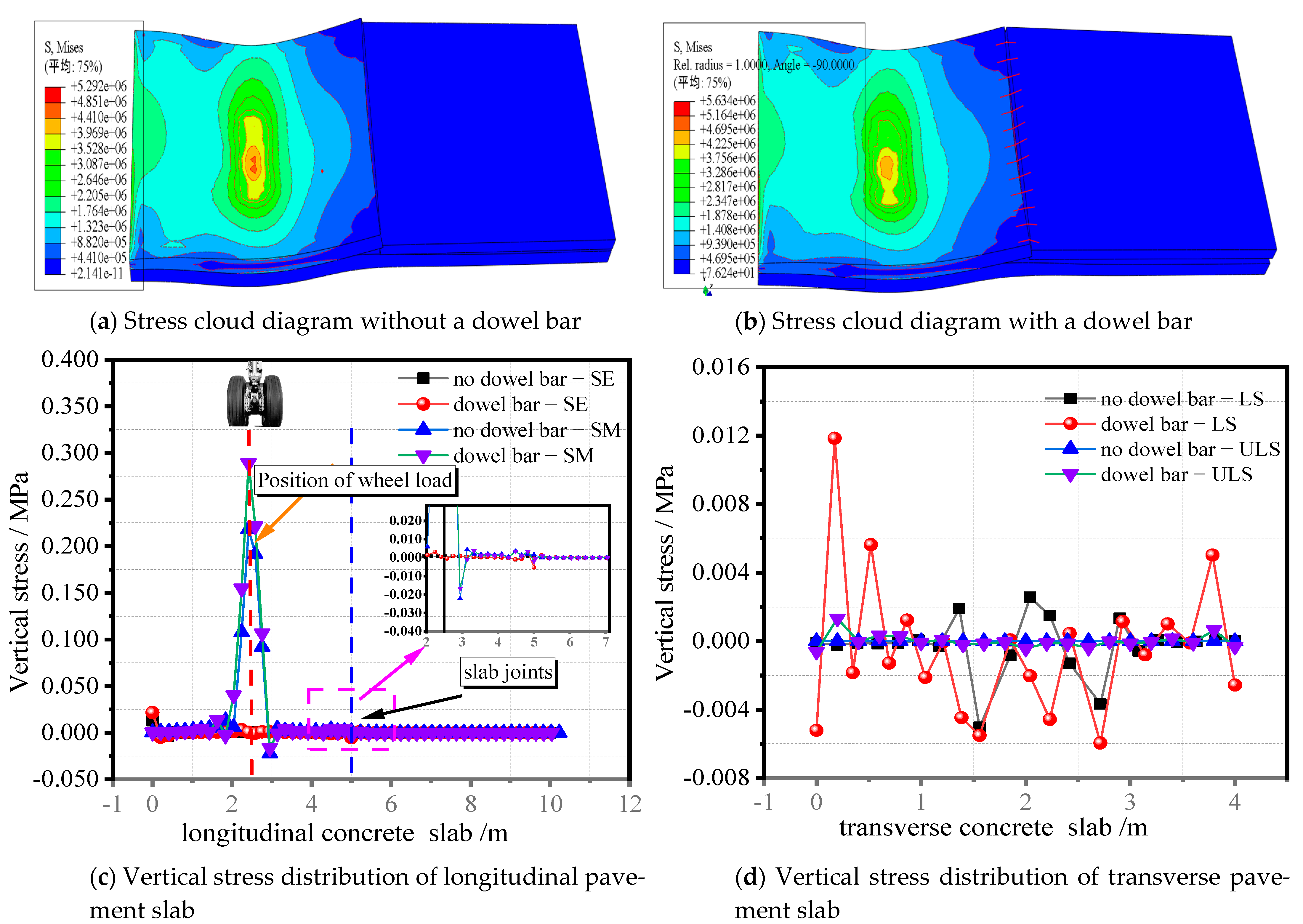
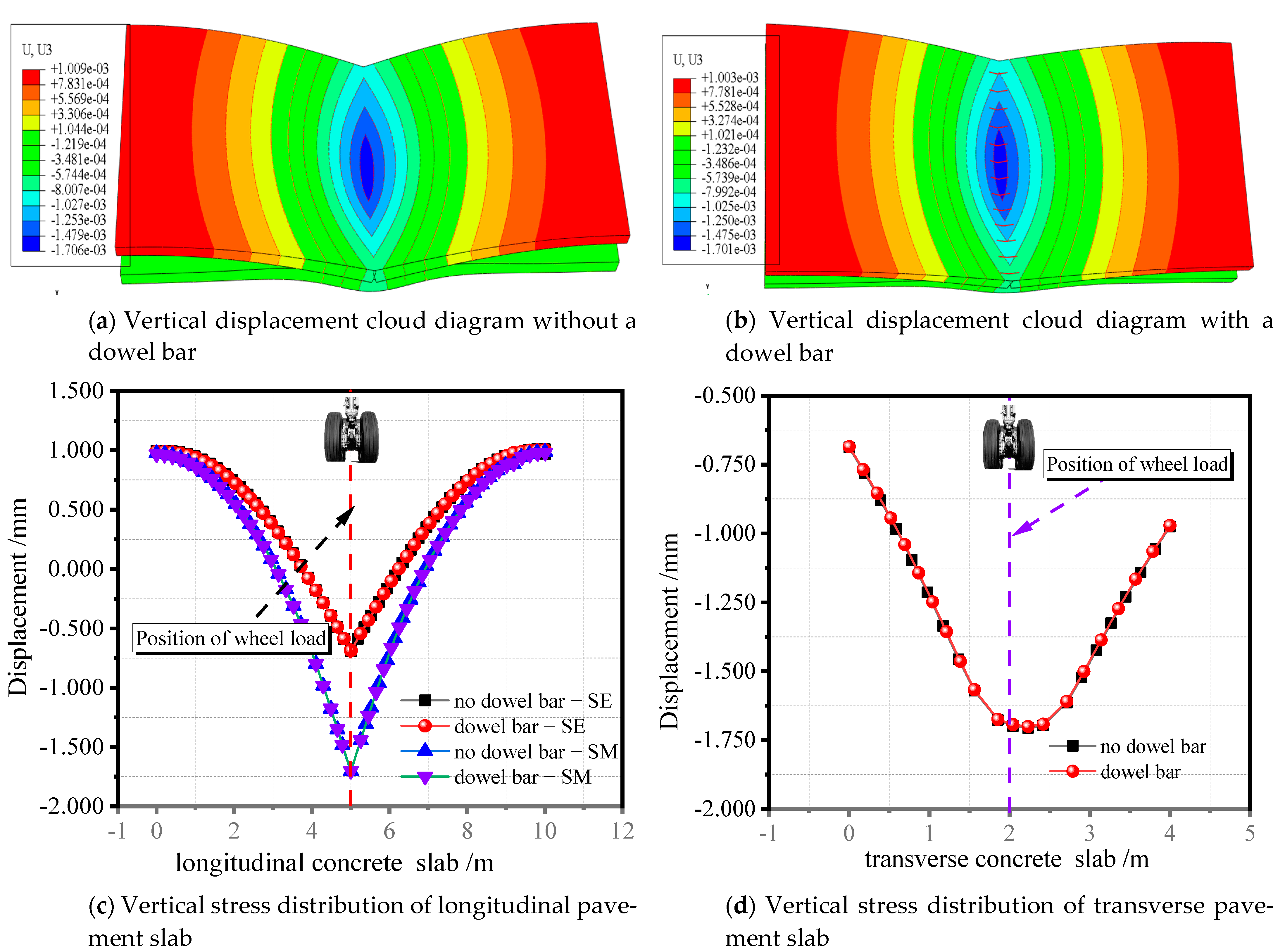
3.1. When an Aircraft Load Acts on the Slab

The stress distribution of the pavement slab with and without the dowel bar is shown in Figure 6a,b, when the aircraft wheel load operates on the center location of the slab. At the wheel load, the bending tensile stress of the paving slab is the greatest. With and without a dowel bar, the top surface of the pavement slab experiences the maximum vertical stress of 0.218 MPa and 0.289 MPa, increasing by 24.56% in each case. As the range is extended, the force continuously lowers, whereas the bending tensile stress at the loaded concrete slab’s (LS and unloaded concrete slab-ULS) edge marginally rises. Moreover, there is no discernible difference between the vertical stress at the connection points of adjacent slabs with and without a dowel bar. In the transverse direction of the pavement slab, the maximum vertical stress is approximately 0.005 MPa for the wheel impression. In the transverse direction of the laden slab, there is a tiny variation between the vertical stress at the axle with and without a dowel bar. There is significant bending tensile stress at the slab’s edge along the transverse direction, and this is what causes the dowel bar’s vertical stress to be compressive at the wheel load of the pavement slab. Additionally, there is compressive stress and bending tensile stress at the wheel load of the pavement without a dowel bar, which vertically reduces to the edge of the slab along the wheel load until it disappears.
As depicted in Figure 7a,b, the displacement of the pavement slab progressively diminishes from the wheel load to the surrounding area, thus exhibiting a displacement diffusion circle, and the longitudinal and transverse displacement of the pavement slab decreases in a parabolic fashion. The slab’s vertical displacement at the longitudinal half of the laden slab, the slab’s edge, and the attenuation coefficient, are all affected when a wheel load is applied to it. These measurements are 1.06 mm, 0.25 mm, and 76.42%, respectively.
The vertical displacement at the center of the laden slab’s longitudinal edge is 0.31 mm, whereas the edge of the slab is 0.17 mm. The attenuation coefficient is 45.16%. Here, in the transverse direction of the loaded slab, the vertical displacement between the wheel load and slab edge increases by 0.28 mm. Figure 7 shows that there is an upward warping deformation along the slab’s edge, and Figure 7c,d also demonstrate that there is an upward warping deformation at the joint between the adjacent slabs. The warping deformation displacement of the loaded slab’s edge is 0.28 mm, and that of the empty slab is 0.05 mm when there is no dowel bar. The displacement caused by warping when a dowel bar is present is 0.28 mm for the loaded slab’s edge and 0.15 mm for the unloaded slab’s edge. Hence, we may conclude that when the dowel bar is introduced, the adjacent slabs share a portion of the load, the deformation of the laden slab occurs on the opposite side, and the deflection load transfer coefficient of the dowel bar is 56.03%.

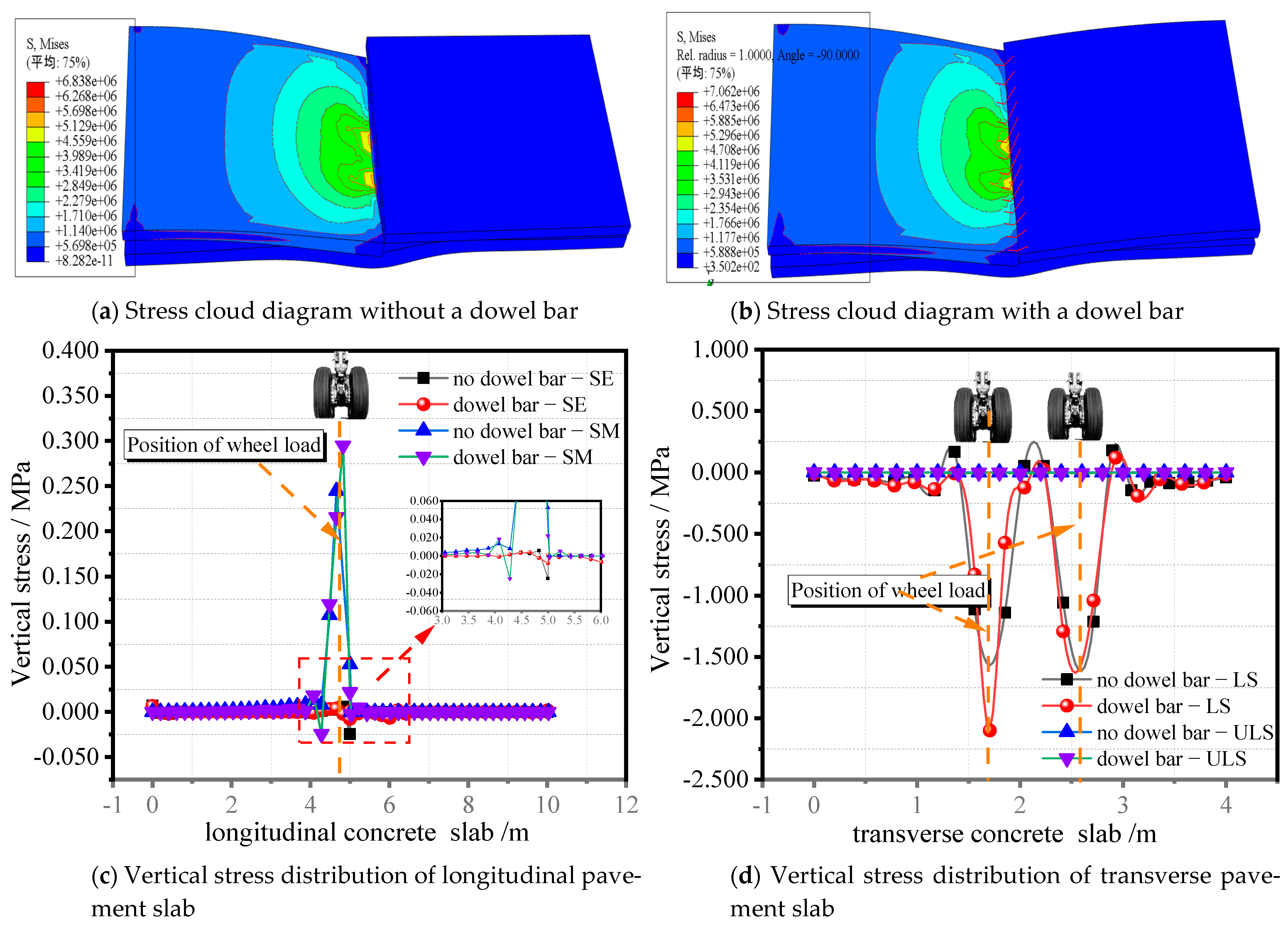
3.2. When the Aircraft’s Load Acts on the Slab Edge

Figure 8 illustrates how the edge of the neighboring slab experiences both bending tensile stress and compressive stress when a wheel load is applied to it. These stresses are present at both the edge of the slab with a dowel bar and the center position of the slab with a dowel bar. When there is a dowel bar at the wheel load, the vertical stress increases by 14.29% to 0.29 MPa from 0.25 MPa when there is no vertical stress. At the edge of the longitudinal slab, only a minor bending tensile stress exists. When there is no dowel bar, the distribution of the bending tensile stress at the transverse wheel load of the pavement slab is similar. When there is a dowel bar present, the vertical stress increases to around 2.10 MPa from 1.13 MPa when there is no vertical stress, and the bending tensile stress rises by 85.84%.
When the aircraft wheel load operates on the edge of the adjacent slab, the maximum vertical displacement of the slab is approximately 1.92 mm, with or without a dowel bar, and the maximum vertical displacement of the slab edge is 0.42 mm. Along the transverse direction of the slab, the vertical displacement from the slab’s center to its edge reduces by 78.13%. The vertical displacement along the longitudinal axis of the slab diminishes parabolically to zero, and the upward warping deformation occurs 2.65 meters away, on the opposite side of the slab. As can be seen from Figure 9, the positioning of the dowel bar has a minimal impact on the stress and deformation of the slab; however, on the sides of the unloaded slab, the vertical displacement increases by 0.52 mm when a dowel bar is present, and the deflection load transfer coefficient is 27.08%.

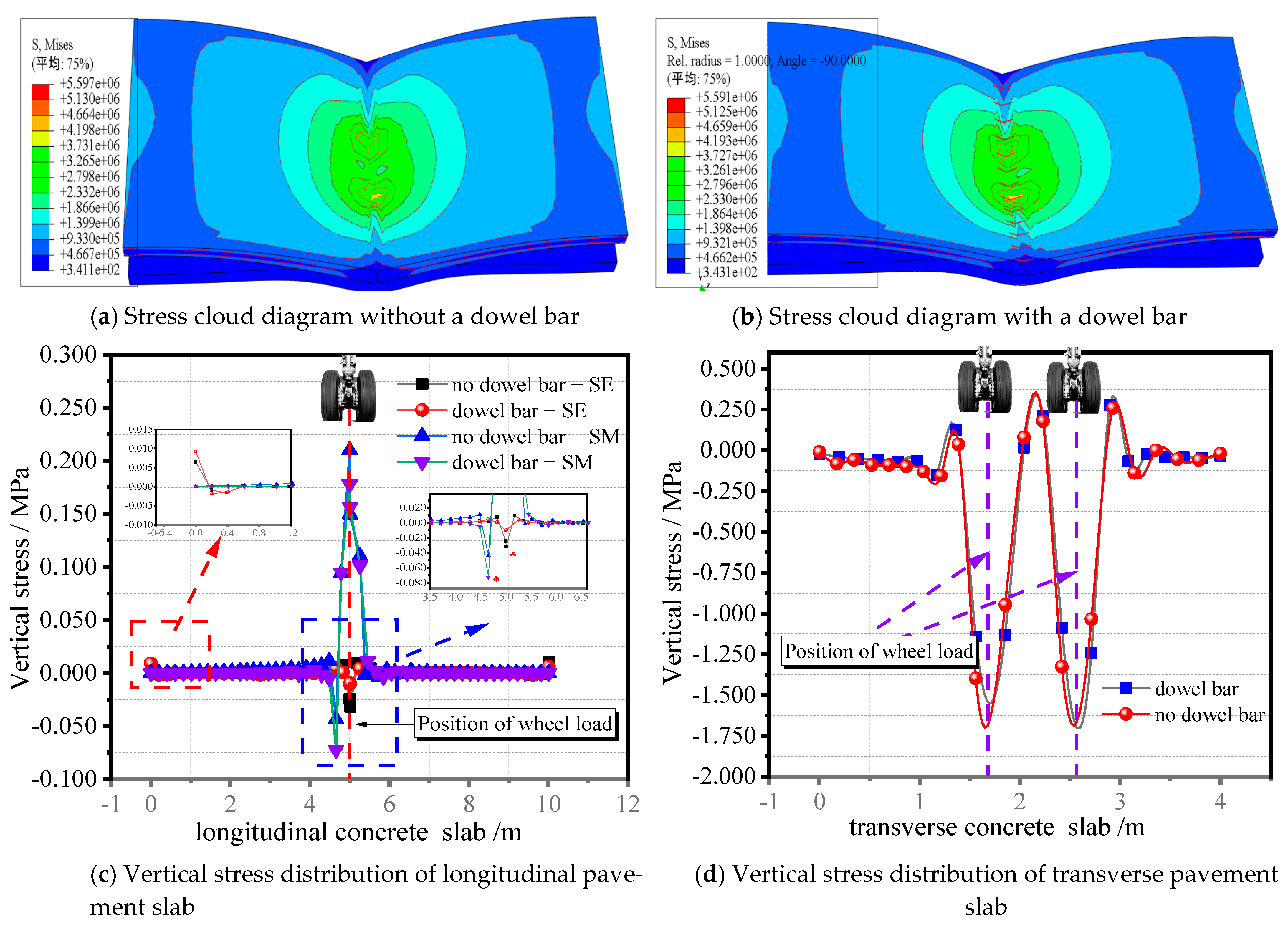
3.3. When the Aircraft Load Acts on Joints

Figure 10 depicts the stress distribution when the wheel load operates on the joint of the pavement slab. The vertical stress is greatest near the joint of the pavement slab. The vertical stress is 0.21 MPa when there is no dowel bar in the slab, and 0.17 MPa when there is, thus showing that the presence of a dowel bar will have a positive influence on the stress at the joint of the pavement slab, resulting in a reduction of stress at the joint of the pavement slab with a dowel bar of 19.05%. There is a significant bending tensile stress on the slab’s edge and middle at the joint where the wheel load position is located, and the bending tensile stress increases when a dowel bar is present. With or without a dowel bar, the bending tensile stress of the slab is 0.07 MPa and 0.04 MPa, respectively. When a dowel bar is present or absent, the slab’s transverse and vertical stress distributions are comparable. If there is a dowel bar present, the vertical stress increases to 1.39 MPa from 1.13 MPa, without a dowel bar. Here, the slab is being placed under a 23.01% increase in flexural–tensile stress.
Figure 11 reveals that the greatest vertical displacement in the longitudinal slab is 1.71 mm, and for the slab edge it is 0.69 mm when the wheel load acts on the junction of the pavement slab, thus representing a reduction of 59.65%. When the transverse wheel load operates, the greatest displacement is 1.71 mm, and when it is transmitted to the slab edge, the vertical displacement is 0.68 mm. Currently, the attenuation coefficient is also 59.65%. Consequently, the vertical displacement of the pavement slab, with and without a dowel bar in the transverse and longitudinal directions, is consistent, thus indicating that the wheel load acting on the dowel bar at the joint of the pavement slab has no discernible effect on the displacement change value, and the longitudinal, transverse, and vertical displacement attenuation law is consistent. In addition, at this time, the vertical displacement distribution of the transverse and longitudinal directions of the pavement reveals that when the wheel load acts on the joint of the adjacent pavement slab, the deflection load transfer of the dowel bar is nearly ineffective; however, it will influence the force at the joint position. When the wheel load acts on the pavement slab, the maximum vertical displacement is 1.06 mm, the displacement attenuation coefficient along the transverse direction is 76.42%, and the longitudinal attenuation coefficient is 45.16%; this can be inferred from comparing the vertical displacement results from Section 3.1, Section 3.2 and Section 3.3. The maximum vertical displacement caused by the wheel load acting on the edge and joint of the adjacent slab is 1.92 mm and 1.71 mm, respectively. The displacement attenuation coefficient along the slab’s transverse direction is 78.13% and 59.65%, respectively. The warping deformation of approximately 0.68 and 0.99 mm upward is produced at another edge of the laden slab, and the vertical displacement along the longitudinal direction of the pavement slab diminishes parabolically to 0. The results suggest that the pavement slab has the weakest force at the slab edge and junction, that the transverse displacement attenuation coefficient of the wheel load operating on the middle of the slab and the adjacent slab edge is similar, and that the attenuation coefficient at the joint position is minimal; therefore, a substantial deflection deformation has been generated over the whole transverse direction of the pavement slab.

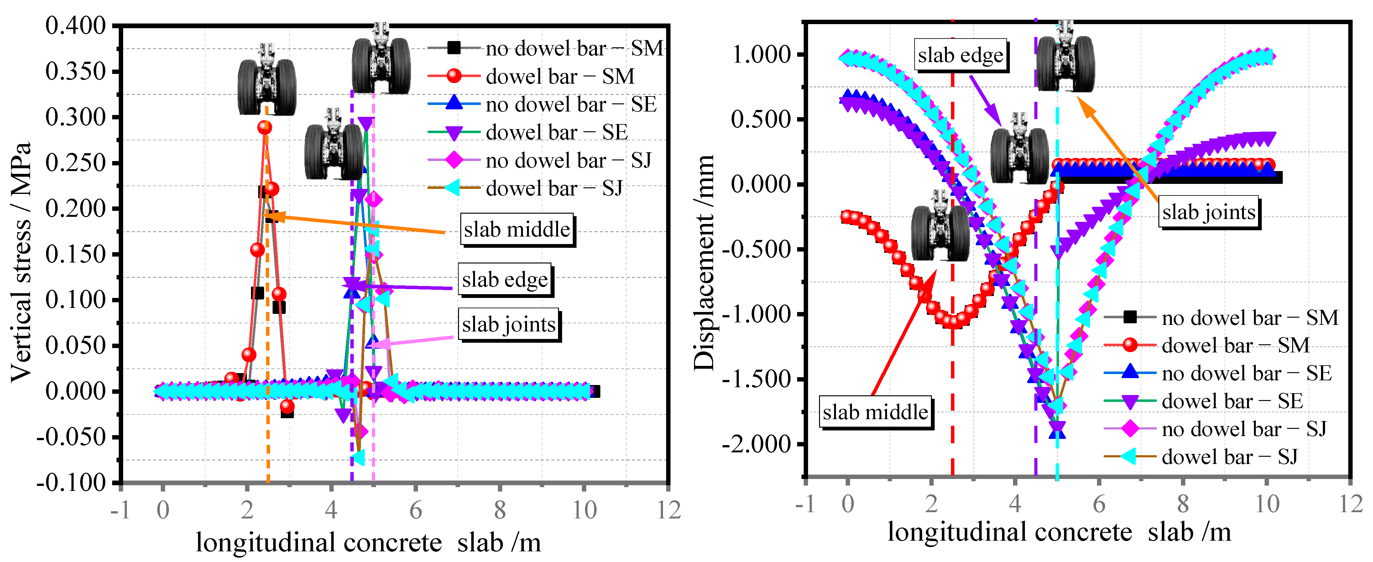
3.4. Changes in Aircraft Load Acting on Different Positions of the Pavement Slab

Following a comparison of the vertical stress and vertical displacement distribution on the middle of the slab, the nearby slab edge, and the junction along the longitudinal pavement length, it can be said that the stress acting on the adjacent slab edge and the joint is more complex, containing both significant bending tensile stress and compressive stress. Moreover, [9,29,35,47] also mentioned that when the aircraft wheel load acts on the pavement slab, there will be shear stress between the slabs; however, these studies focus on the compressive, flexural, and tensile strengths when the aircraft wheel load acts on the pavement slab, and thus, they do not consider the influence of shear stress on the pavement slab.
Furthermore, the connection between the slab edge and the adjacent pavement may be defined as the place where the aircraft’s wheel load acts on the prefabricated pavement slab, which is most unfavorable. As a result, the most unfavorable position should be taken into account when designing the precast airport pavement. This is illustrated by the comparison of the stress values at various positions; the wheel load operating on the pavement is present in Table 4. According to Figure 12, it can be inferred that the addition of a dowel bar has a minimal impact on the level of stress on the pavement, but it has a beneficial impact on the transmission load of the slab of pavement next to it.
According to Section 3.1, Section 3.2 and Section 3.3, it can be concluded that the precast airport pavement, when subjected to the aircraft’s wheel load, will exhibit a warping deformation around the slab’s perimeter. As the smoothness of the airport cement concrete pavement is a crucial aspect in determining the safety of the airport and the aircraft’s landing, the deformation will have a severe negative influence on the pavement’s smoothness. The deformation of the slab generated by the airport’s prefabricated pavement grouting layer is an important basis for researching the application and construction of the precast airport pavement. This is because it is necessary to manage the warping deformation of the slab and take into account the coupling impact of the temperature wheel load and the mechanical features of the direction of the pavement’s thickness [42,43]. Based on the aforementioned factors, more research will be done in the future on the mechanical characteristics of the concrete precast pavement used for airport runways.

3.5. Laboratory Test Verification

Based on the above analysis results, to further verify the accuracy of the calculations and analysis, and the effectiveness of the finite element simulation, the laboratory test data are used to compare the simulation results of the displacement and stress of the aircraft wheel load acting on the pavement slab [49,50,51,52]. When the aircraft’s wheel load acts on the pavement slab, in the laboratory test, the displacement and stress placed on the slab, and its corresponding changes, are shown in Figure 13 and Figure 14, respectively.
As can be seen from Figure 13 and Figure 14, when the aircraft’s wheel load acts on the pavement slab, the laboratory test data are approximately consistent with the finite element simulation results, which is expected; however, there are some differences between the laboratory test data and the calculation results of the finite element model, which may be due to the following reasons:
  • the results are different due to the different conditions in laboratory test facilities and human errors;
  • the results do not consider the stress and deformation caused by temperature changes on the pavement slab.
Therefore, future research will continue to carry out investigations into the influence of the aircraft’s wheel load, coupled with temperature, on the laying of prefabricated runway slabs. Moreover, future research will also continue to verify these results, as well as the engineering applications of the finite element simulation results from laboratory tests and full-scale tests.

4. Conclusions

This paper presents the elastic layered Boussinesq theory and finite element simulation in order to study the stress field and displacement field distribution law of aircraft wheel loads, which act on the central slab, the edge of adjacent slabs, and the junctions of the adjacent slabs of precast concrete airport pavement. Then, the effect of adding a dowel bar to reduce the burden of the load on the pavement slab, and the load transfer of the adjacent slab, were compared and investigated. Finally, the laboratory test data were compared with the simulation calculation results. The following conclusions can be drawn:
(1)
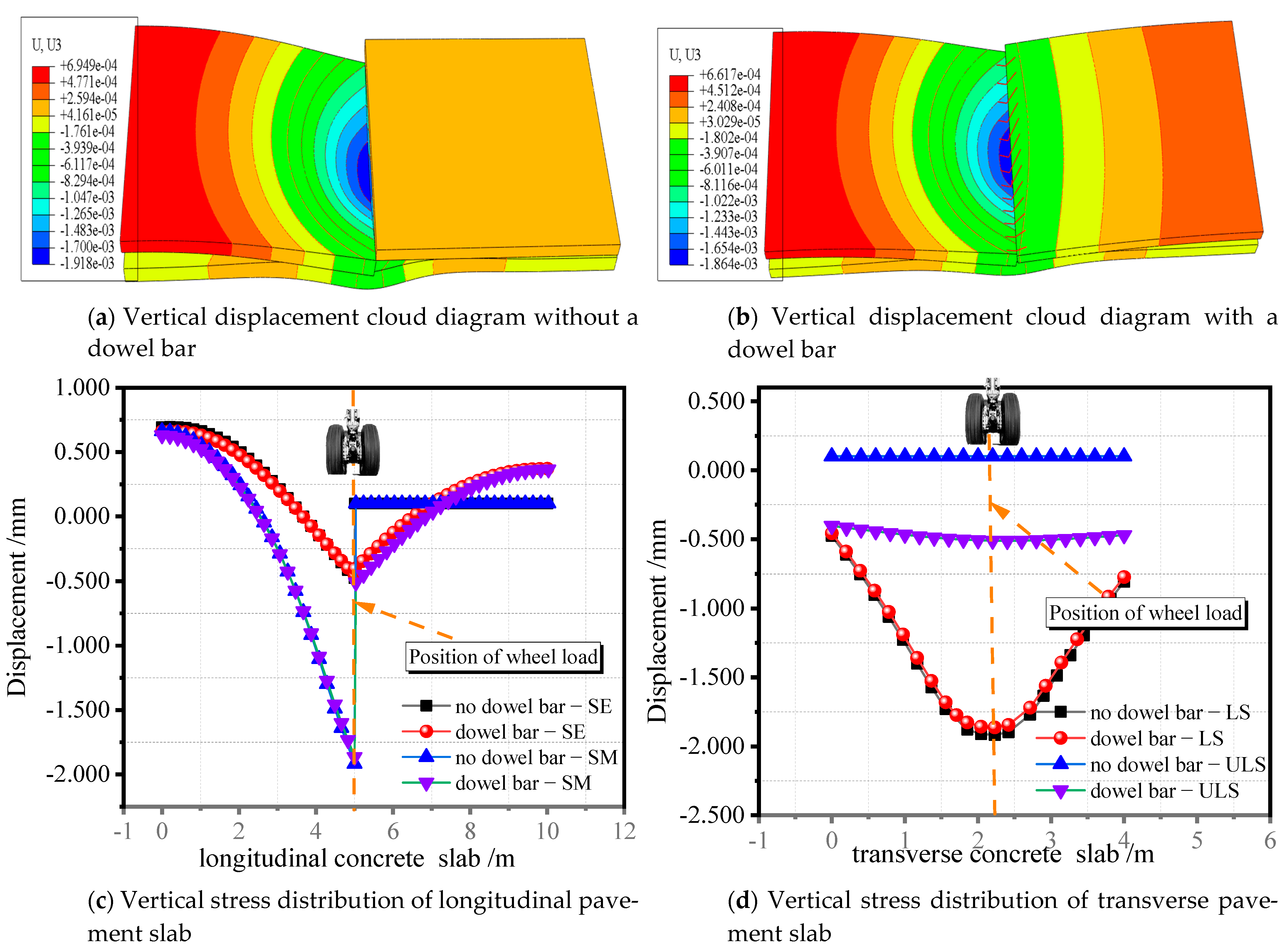
The vertical displacement of the slab at the slab’s edge, and the connection between neighboring slabs, was relatively significant, with the greatest vertical displacement measuring at 1.92 mm and 1.71 mm, respectively. The coefficient of the transverse displacement attenuation of the wheel load operating on the center of the slab and the edge of neighboring slabs was comparable. A high deflection deformation on the transverse direction of the pavement slab was present, together with a small attenuation coefficient and a complex stress condition at the junction point.
(2)
The effect of the dowel bar on the load-bearing pavement slab was minimal, regardless of the slab’s different positions. The deflection load transfer coefficient of the loaded slab, relative to the unloaded slab, was 56.03% when the wheel load was acting on the center of the slab. The deflection load transfer coefficient that was measured when the wheel load was acting at the slab’s edge, was 27.08%. The conclusion that the dowel bar’s load transfer efficiency was lower when the aircraft wheel load was closer to another unloaded slab is based on the fact that when the wheel load acted on the joint of adjacent pavement slabs, the dowel bar rarely modified the load transfer of the pavement; however, it did affect the force at the joint point.
(3)
The edges of nearby slabs underwent the most vertical stress after the dowel bar was introduced, followed by center of the slab, and finally, the slab’s joints. The three vertical stresses were 0.295 MPa, 0.289 MPa, and 0.178 MPa. The junctions experienced the highest bending stress, which was then followed by the slab’s edges, and finally, the center of the slab. The bending stresses were 0.072 MPa, 0.025 MPa, and 0.016 MPa, respectively.
(4)
After comparing the laboratory test data with the simulation calculation, the results were found to be similar. The joint between the edge of the precast pavement slab and the neighboring pavement slab was the most unfavorable position of the precast pavement slab under the aircraft’s wheel load. This finding may help to understand the illness and damage mechanisms of existing pavement slab edges and joints. The warping distortion of the pavement slab along its edges and its surroundings, caused by the wheel load, would have a significant impact on the smoothness of the airport’s cement concrete pavement; therefore, in the future, it will be necessary to use theoretical numerical simulations and field tests to further verify the warping deformation of the slab, and to investigate the deformation of the slab caused by the effect of the temperature, the wheel load, and the stress characteristics along the direction of the slab’s thickness.

Author Contributions

C.L.: Conceptualization, Data curation, Formal analysis, Writing—original draft, Writing—review and editing. X.C.: Conceptualization, Supervision, L.W.: Funding acquisition, Resources. J.Z. and Z.C.: Conceptualization, Data curation, Formal analysis. F.L. and P.B.: Writing—Review and Editing. All authors have read and agreed to the published version of the manuscript.

Funding

This research was funded by Natural Science Foundation of Shaanxi Province grant number [2022JQ-398] and Xi’an Young Talent Lifting Program grant number [095920221380].

Institutional Review Board Statement

Not applicable.

Informed Consent Statement

Not applicable.

Data Availability Statement

Not applicable.

Acknowledgments

We would like to express our sincerest gratitude to the anonymous unidentified reviewers for providing us with constructive and insightful comments and suggestions. Thanks to the Institute of Defense Engineering, AMS, PLA provided the experiment conditions.

Conflicts of Interest

The authors declare that they have no known competing financial interests or personal relationships that could have influenced the work in this paper.

References

  1. Faheem, M.; Tahir, M.; Mustafa, M.; Bakri, A. Potential of industrial By-Products based geopolymer for rigid concrete pavement application. Constr. Build. Mater. 2022, 344, 128190. [Google Scholar] [CrossRef]
  2. Fang, M.; Zhou, R.; Ke, W.; Tian, B.; Zhang, Y.; Liu, J. Precast system and assembly connection of cement concrete slabs for road pavement: A review. J. Traffic Transp. Eng. (Engl. Ed.) 2022, 9, 208–222. [Google Scholar] [CrossRef]
  3. Chhorn, C.; Hong, S.J.; Lee, S.W. A study on performance of roller-compacted concrete for pavement. Constr. Build. Mater. 2017, 153, 535–543. [Google Scholar] [CrossRef]
  4. Chen, Y.; Cen, G.; Cui, Y. Comparative study on the effect of synthetic fiber on the preparation and durability of airport pavement concrete. Constr. Build. Mater. 2018, 184, 34–44. [Google Scholar] [CrossRef]
  5. Ganiron, T.U.J. Effects of Human Hair Additives in Compressive Strength of Asphalt Cement Mixture. Int. J. Adv. Sci. Technol. 2014, 67, 11–22. [Google Scholar] [CrossRef]
  6. Seehra, S.S.; Gupta, S.; Kumar, S. Rapid setting magnesium phosphate cement for quick repair of concrete pavements—Characterisation and durability aspects. Cem. Concr. Res. 1993, 23, 254–266. [Google Scholar] [CrossRef]
  7. Peng, P.; Yuan, Z.; Tian, B.; Niu, K. Research on application of precast-assemble technology to road maintenance engineering. Appl. Mech. Mater. 2013, 361–363, 1693–1698. [Google Scholar] [CrossRef]
  8. Jordaan, G.J.; Steyn, W.J.V. Nanotechnology Applications towards Sustainable Road Surface Maintenance and Effective Asset Protection, Generating Rapid Employment Opportunities in a Post COVID-19 Era. Appl. Sci. 2022, 12, 2628. [Google Scholar] [CrossRef]
  9. Wang, Y.; Kong, L.; Chen, Q.; Lau, B.; Wang, Y. Research and application of a black rapid repair concrete for municipal pavement rehabilitation around manholes. Constr. Build. Mater. 2017, 150, 204–213. [Google Scholar] [CrossRef]
  10. Tayabji, S.; Tyson, S. Precast concrete pavement innovations, performance and best practices. Concr. Int. 2014, 39, 41–46. [Google Scholar]
  11. Tayabji, S.; Ye, D.; Buch, N. Precast concrete pavements: Technology overview and technical considerations. PCI J. 2013, 58, 112–128. [Google Scholar] [CrossRef] [Green Version]
  12. Murugan, R.B.; Natarajan, C.; Chen, S.E. Material development for a sustainable precast concrete block pavement. J. Traffic Transp. Eng. (Engl. Ed.) 2016, 3, 483–491. [Google Scholar] [CrossRef]
  13. Merritt, D.; McCullough, B.F.; Burns, N.H. Feasibility of using precast concrete panels to expedite construction of portland cement concrete pavements. Transp. Res. Rec. 2001, 1761, 3–9. [Google Scholar] [CrossRef]
  14. Hu, W.; Li, Y.; Yuan, H. Review of Experimental Studies on Application of FRP for Strengthening of Bridge Structures. Adv. Mater. Sci. Eng. 2020, 2020. [Google Scholar] [CrossRef]
  15. Noël, M.; Soudki, K. Fatigue Behavior of Full-Scale Slab Bridge Strips with FRP Reinforcement. J. Compos. Constr. 2015, 19, 04014047. [Google Scholar] [CrossRef]
  16. Ma, H.; Zhang, Z. Paving an engineered cementitious composite (ECC) overlay on concrete airfield pavement for reflective cracking resistance. Constr. Build. Mater. 2020, 252, 119048. [Google Scholar] [CrossRef]
  17. Hu, H.; Dong, C.Z.; Wang, J.; Chen, J. Experimental study of the fatigue performance of the bonding surfaces and load-bearing capacity of a large-scale severely damaged hollow slab strengthened by cfrp. Sustainability 2021, 13, 12179. [Google Scholar] [CrossRef]
  18. Sorelli, L.G.; Meda, A.; Plizzari, G.A. Steel fiber concrete slabs on ground: A structural matter. ACI Struct. J. 2006, 103, 551–558. [Google Scholar] [CrossRef]
  19. Xiaochun, Q.; Xiaoming, L.; Xiaopei, C. The applicability of alkaline-resistant glass fiber in cement mortar of road pavement: Corrosion mechanism and performance analysis. Int. J. Pavement Res. Technol. 2017, 10, 536–544. [Google Scholar] [CrossRef]
  20. Mounes, S.M.; Karim, M.R.; Mahrez, A.; Khodaii, A. An overview on the use of geosynthetics in pavement structures. Sci. Res. Essays 2011, 6, 2251–2258. [Google Scholar] [CrossRef]
  21. Qu, B.; Weng, X.z.; Zhang, J.; Mei, J.j.; Guo, T.x.; Li, R.f.; An, S.h. Analysis on the deflection and load transfer capacity of a prefabricated airport prestressed concrete pavement. Constr. Build. Mater. 2017, 157, 449–458. [Google Scholar] [CrossRef]
  22. Hargett, E.R. Prestressed concrete panels for pavement construction. PCI J. 1970, 43–49. [Google Scholar] [CrossRef]
  23. Boyd, A.J.; Liang, N.; Green, P.S.; Lammert, K. Sprayed FRP repair of simulated impact in prestressed concrete girders. Constr. Build. Mater. 2008, 22, 411–416. [Google Scholar] [CrossRef]
  24. Issa, M.A.; Idriss, A.T.; Kaspar, I.I.; Khayyat, S.Y. Full depth precast and precast, prestressed concrete bridge deck panels. PCI J. 1995, 40. [Google Scholar] [CrossRef]
  25. Sacks, R.; Eastman, C.M.; Lee, G. Process Model Perspectives on Management and Engineering Procedures in the Precast/Prestressed Concrete Industry. J. Constr. Eng. Manag. 2004, 130, 130–206. [Google Scholar] [CrossRef]
  26. JBull, W.; Woodford, C.H. Design of precast concrete pavement units for rapid maintenance of runways. Comput. Struct. 1997, 64, 857–864. [Google Scholar] [CrossRef]
  27. Senseney, C.T.; Smith, P.J.; Snyder, M.B. Precast concrete paving repairs at vancouver international airport. Transp. Res. Rec. 2021, 2675, 439–448. [Google Scholar] [CrossRef]
  28. Chen, Y.S.; Murrell, S.D.; Larrazabal, E. Precast concrete (PC) pavement tests on Taxiway DD at LaGuardia Airport. In Airfield Pavements: Challenges and New Technologies; ASCE: Reston, VA, USA, 2004. [Google Scholar]
  29. Abdualla, H.; Ceylan, H.; Kim, S.; Taylor, P.C.; Gopalakrishnan, K.; Cetin, K. Hydronic Heated Pavement System Using Precast Concrete Pavement for Airport Applications. In Proceedings of the International Conference on Transportation and Development 2018: Airfield and Highway Pavements, Pittsburgh, PA, USA, 15–18 July 2018; American Society of Civil Engineers: Reston, VA, USA, 2018; Volume 2018, pp. 16–24. [Google Scholar] [CrossRef]
  30. Ping, H.; Qi, Z.D.; Hui, L.; Feng, S.G.; Jun, T.Y. Research of prestressed concrete hollow multi-ribbed composite box girder. Adv. Mater. Res. 2012, 368–373, 705–709. [Google Scholar] [CrossRef]
  31. Šrámek, M.; Novák, J. Non-linear analysis of precast concrete element for airport pavement. Solid State Phenom. 2019, 292 SSP, 153–158. [Google Scholar] [CrossRef]
  32. Davis, E.H.; Poulos, H.G. The use of elastic theory for settlement prediction under three-dimensional conditions. Geotechnique 1968, 18, 67–91. [Google Scholar] [CrossRef]
  33. Li, C.; Ashlock, J.C.; Lin, S.; Vennapusa, P.K.R. In situ modulus reduction characteristics of stabilized pavement foundations by multichannel analysis of surface waves and falling weight deflectometer tests. Constr. Build. Mater. 2018, 188, 809–819. [Google Scholar] [CrossRef]
  34. Marecos, V.; Solla, M.; Fontul, S.; Antunes, V. Assessing the pavement subgrade by combining different non-destructive methods. Constr. Build. Mater. 2017, 135, 76–85. [Google Scholar] [CrossRef]
  35. Li, Y.; Song, G.; Cai, J. Mechanical Response Analysis of Airport Flexible Pavement Above Underground Infrastructure Under Moving Wheel Load. Geotech. Geol. Eng. 2017, 35, 2269–2275. [Google Scholar] [CrossRef]
  36. Maina, J.W.; Ozawa, Y.; Matsui, K. Linear elastic analysis of pavement structure under non-circular loading. Road Mater. Pavement Des. 2012, 13, 403–421. [Google Scholar] [CrossRef]
  37. Liu, S.; Ling, J.; Tian, Y.; Hou, T.; Zhao, X. Random Vibration Analysis of a Coupled Aircraft/Runway Modeled System for Runway Evaluation. Sustainability 2022, 14, 2815. [Google Scholar] [CrossRef]
  38. Liu, S.; Tian, Y.; Liu, L.; Xiang, P.; Zhang, Z. Improvement of boeing bump method considering aircraft vibration superposition effect. Appl. Sci. 2021, 11, 2147. [Google Scholar] [CrossRef]
  39. Tian, Y.; Liu, S.; Liu, L.; Xiang, P. Optimization of international roughness index model parameters for sustainable runway. Sustainability 2021, 13, 2184. [Google Scholar] [CrossRef]
  40. Gagliardi, P.; Teti, L.; Licitra, G. A statistical evaluation on flight operational characteristics affecting aircraft noise during take-off. Appl. Acoust. 2018, 134, 8–15. [Google Scholar] [CrossRef]
  41. Xu, H.; Xiao, K.; Cheng, J.; Yu, Y.; Liu, Q.; Pan, J.; Chen, J.; Chen, F.; Fu, Q. Characterizing aircraft engine fuel and emission parameters of taxi phase for Shanghai Hongqiao International Airport with aircraft operational data. Sci. Total Environ. 2020, 720, 137431. [Google Scholar] [CrossRef]
  42. Wang, H.; Al-Qadi, I.L. Combined effect of moving wheel loading and three-dimensional contact stresses on perpetual pavement responses. Transp. Res. Rec. 2009, 2095, 53–61. [Google Scholar] [CrossRef]
  43. Dong, Z.; Ma, X. Analytical solutions of asphalt pavement responses under moving loads with arbitrary non-uniform tire contact pressure and irregular tire imprint. Road Mater. Pavement Des. 2018, 19, 1887–1903. [Google Scholar] [CrossRef]
  44. Ameri, M.; Mansourian, A.; Khavas, M.H.; Aliha, M.R.M.; Ayatollahi, M.R. Cracked asphalt pavement under traffic loading—A 3D finite element analysis. Eng. Fract. Mech. 2011, 78, 1817–1826. [Google Scholar] [CrossRef]
  45. Shi, C.X.; Guo, Z.Y. Mechanical properties of asphalt pavement structure in highway tunnel. J. Shanghai Jiaotong Univ. 2008, 13, 206–210. [Google Scholar] [CrossRef]
  46. Lai, Y.; Liu, Y.; Ma, D. Automatically melting snow on airport cement concrete pavement with carbon fiber grille. Cold Reg. Sci. Technol. 2014, 103, 57–62. [Google Scholar] [CrossRef]
  47. Tian, Y.; Xiang, P.; Liu, S.; Ling, J.; Tang, R. Improving airport runway rigid pavement design using influence surfaces. Constr. Build. Mater. 2021, 284, 122702. [Google Scholar] [CrossRef]
  48. Guo, T.; Liu, Z.X.; Zhu, J.S. Fatigue reliability assessment of orthotropic steel bridge decks based on probabilistic multi-scale finite element analysis. Adv. Steel Constr. 2015, 11, 334–346. [Google Scholar] [CrossRef]
  49. Priddy, L.P.; Bly, P.G.; Jackson, C.J.; Flintsch, G.W. Full-scale field testing of precast Portland cement concrete panel airfield pavement repairs. Int. J. Pavement Eng. 2014, 15, 840–853. [Google Scholar] [CrossRef]
  50. Taheri, V.; Fakhri, M.; Hayati, P. Evaluation of airfield concrete block pavements based on 3-D modelling and plate loading test. Constr. Build. Mater. 2021, 280, 122441. [Google Scholar] [CrossRef]
  51. Maros, H.; Juniar, S. Construction and Preliminary Monitoring of the Georgetown, Texas Precast Prestressed Concrete Pavement; Texas Department of Transportation: Austin, TX, USA, 2016.
  52. Zhang, J.; Weng, X.; Yang, B.; Li, Y.; Liu, J.; Jiang, L. Bonding characteristics of grouting layer in Prefabricated Cement Concrete Pavement. Constr. Build. Mater. 2017, 145, 528–537. [Google Scholar] [CrossRef]
Figure 1. Schematic diagram of the aircraft load pavement slab and quarter aircraft wheel load vibration model.
Applsci 12 09826 g001
Figure 2. Equivalent wheel imprint area of the rectangle, combined with the wheel imprints.
Applsci 12 09826 g002
Figure 3. Schematic diagram of the wheel imprint of the main landing gear acting on airport pavement.
Applsci 12 09826 g003
Figure 4. Schematic diagram of the aircraft load pavement slab and quarter aircraft wheel load vibration model. Schematic diagram of finite element meshing model of pavement slab structure.
Applsci 12 09826 g004
Figure 5. Diagram of an aircraft’s wheel load acting on different positions of the pavement slab.
Applsci 12 09826 g005
Figure 6. Stress distribution of pavement slabs under the aircraft’s wheel load.
Applsci 12 09826 g006
Figure 7. Displacement distribution of the aircraft’s wheel load acting on the pavement slab.
Applsci 12 09826 g007
Figure 8. Stress distribution of the aircraft’s wheel load acting on the edge of adjacent slabs.
Applsci 12 09826 g008
Figure 9. Vertical displacement distribution of the aircraft’s wheel load acting on the edge of adjacent slabs.
Applsci 12 09826 g009
Figure 10. Stress distribution of the aircraft’s wheel load on the joints of adjacent pavement slabs.
Applsci 12 09826 g010
Figure 11. Displacement distribution of the aircraft’s wheel load acting on the joint of the pavement slab.
Applsci 12 09826 g011
Figure 12. Comparison of stress states caused by the aircraft’s wheel load acting on different positions of the pavement slab.
Applsci 12 09826 g012
Figure 13. Laboratory test [49,50,51,52].
Applsci 12 09826 g013
Figure 14. Comparison between the laboratory test and simulation results [49,50,51,52].
Applsci 12 09826 g014
Table 1. Parameters of B737-800 aircraft.
Aircraft ParametersValue
Suspension system mass (m2)/kN328
Non-suspension system mass (m1)/kN74.55
Rear landing gear tire stiffness coefficient (k1)/kN·m−19600
Rear suspension stiffness factor (k2)/kN·m−14800
Rear landing gear tire damping factor (c1)/kN·m−1·s−124
Rear suspension buffer damping factor (c2)/kN·m−1·s−120
Table 2. B737-800 model calculation reference data.
Maximum ramp weight792.60 kNMain landing gear spacing5.72 m
Maximum takeoff weight790.04 kNNumber of main landing gear2
Maximum landing weight663.80 kNLanding-gear tread0.86
Maximum fuel-free weight627.50 kNMain landing gear configurationDouble round
Empty weight414.30 kNMain landing gear tire pressure1.47 MPa
Main landing gear load distribution factor0.950
Table 3. Parameters of the pavement structure layer.
ParametersCement Concrete PavementCement-Stabilized MacadamBase
Thickness/m0.240.3--
Elasticity modulus/MPa38,00015002000
Poisson’s ratio0.150.250.3
Table 4. Stress values at different positions of pavements.
Position of Wheel LoadVertical Stress/MPaFlexural-Tensile Stress/MPa
No Dowel BarDowel BarNo Dowel BarDowel Bar
Slab EdgeSlab MiddleSlab EdgeSlab MiddleSlab EdgeSlab MiddleSlab EdgeSlab Middle
SM0.0130.0220.2180.2890.0030.0050.0220.016
SE0.0070.0070.2450.2950.0240.0080.0010.025
SJ0.0100.0090.2100.1780.0320.0100.0440.072
Publisher’s Note: MDPI stays neutral with regard to jurisdictional claims in published maps and institutional affiliations.

