Article

Elastic Analysis of Three-Layer Concrete Slab Based on Numerical Homogenization with an Analytical Shear Correction Factor

by
Natalia Staszak
1,
Anna Szymczak-Graczyk
2 and
Tomasz Garbowski
3,*
1
Doctoral School, Department of Biosystems Engineering, Poznan University of Life Sciences, Wojska Polskiego 28, 60-637 Poznań, Poland
2
Department of Construction and Geoengineering, Poznan University of Life Sciences, Piątkowska 94, 60-649 Poznań, Poland
3
Department of Biosystems Engineering, Poznan University of Life Sciences, Wojska Polskiego 50, 60-627 Poznań, Poland
*
Author to whom correspondence should be addressed.
Appl. Sci. 2022, 12(19), 9918; https://doi.org/10.3390/app12199918
Submission received: 14 September 2022 / Revised: 23 September 2022 / Accepted: 28 September 2022 / Published: 1 October 2022

Abstract

:
Sandwich structures are widely used in construction, as well as in the aviation, spaceship, and electronics industries. The interesting result, among others, is the fact that individual layers can be freely selected to meet the planned requirements. In the case of sandwich structures in construction, they must meet the requirements of load-bearing capacity, thermal, and acoustic insulation, and additionally, they must be resistant to biological and chemical corrosion. The paper presents calculation algorithms for Hoff’s three-layer panels. In the first case, the well-known and proven method of finite differences in variation terms was used, assuming actual geometrical and material parameters. In the second case, the numerical homogenization method of the layered panel was used, replacing the stiffnesses of individual layers with a homogeneous equivalent plate with substitute stiffness corrected in shearing by an analytically derived shear correction factor. A comparative analysis of the results of the calculations with the use of both approaches was carried out. A good agreement between the displacement values and the calculated cross-sectional forces was obtained. On this basis, it can be assumed that the static analysis of a slab by simplified methods using numerical homogenization with an analytical shear correction factor is appropriate and can be applied to layer structures.

1. Introduction

Sandwich panels are widely used in construction due to the possibility of a deliberate selection of the properties of individual layers. In the initial period, the sandwich panel theory was mainly developed for applications in the aviation, space, and electronics and medicine industries [1,2,3]. Sandwich panels used in the construction industry must carry high utility loads, provide good thermal and acoustic insulation, and be resistant to biological and chemical corrosion. The standard sandwich construction has two homogeneous top layers and a soft homogeneous core in between. However, such a structure is characterized by a large heterogeneity of material and geometric properties between the outer layers and the core [4]. The top layers of the plate are composed of steel or concrete in order to ensure adequate strength of the element. On the other hand, the core is usually composed of a material with poor strength parameters, e.g., mineral wool, foam, and polyurethane. Its function is only to provide adequate thermal insulation. For this reason, often in the contact plane of the component layers, it is difficult to define stresses caused by thermal and mechanical loads [5,6,7]. The introduction of non-homogeneous materials, such as functionally graded materials (FGM), made layered structures even more attractive [8,9], and they are used, for example, in the construction of submarines or space landers. The use of FGM materials reduces the inter-layer stresses and thermal stresses, improving the mechanical properties of sandwich structures [10,11].
The literature contains a number of works on the statics of sandwich panels subjected to mechanical [12,13,14,15,16,17,18] and thermal [19,20,21,22,23,24] loads, as well as on various types of constituent materials [1,25]. The materials used for sandwich construction have a decisive influence on their statistical performance. By increasing the deformation modulus of the core material, its share of the work of the entire sandwich structure is significantly increased. The most advantageous solution was the experimental validation of the model used to carry out numerical tests [19,26,27,28,29]. Algorithmizing the calculation of sandwich panels assumes their actual geometric and material data would be a very sought-after solution in the design and creation of new types of structures in this category.
Taking into account the possible construction materials for both the outer and middle layers, it was found that the most appropriate model reflecting the work of a sandwich panel would be the model of a three-dimensional panel given by Hoff [30]. For the model adopted in the work, equilibrium equations were given in the form of a system of three partial differential equations derived by Hoff [30] or the equivalent of one eight-order differential equation given in [31,32]. This can be effectively computed by the finite difference method (FDM). As an alternative to the FDM approach, the well-established Finite Element Method (FEM) can be used, however, for sandwich panels with a large difference in stiffness between the outer layers and the core, the full 3D model should be used for the calculation. Another approach, which is extremely effective, especially when it is not necessary to fully model the layered structures, is numerical homogenization [33].
Performing deformation analysis of sandwich panels in an analytical manner results in a large number of complicated equations to be solved, which is associated with being a time-consuming calculation and a high possibility of making a mistake. Additionally, 3D modeling of such plate cross-sections is not very economical. Therefore, the possible solution may be to use the available homogenization methods. Thanks to which, the complex cross-section of a multi-layer panel can be reduced to a single-layer substitute model with equivalent parameters. This approach ensures that the behavior of the equivalent model is very similar to that of the three-dimensional reference model. The issue of the homogenization of complex cross-sections has been the subject of numerous studies in recent years. One can distinguish, inter alia, the methods of periodical homogenization [34], asymptotic homogenization [35], or the method based on inverse analysis [36]. Another type of homogenization based on strain energy was proposed in [37]. It is based on the use of strain energy, assuming mechanical equivalence between the simplified model and the representative volume element (RVE) of a 3D sample. The homogenization method based on strain energy equivalency applied to layer structures was proposed by Biancolini [38] and then improved by Garbowski and Gajewski [39]. This homogenization method was also used to calculate a perforated corrugated board [40] or elements of engineering structures, e.g., prefabricated floor slabs of the “Filigran” type [33] or thin-walled beams with periodic holes [41].
The aim of the work is to present a method for calculating the Hoff three-layer plate using the finite difference method using the variational approach and to numerically homogenize and enhance analytically derived shear correction factors. Both numerical calculations were limited to elastic analysis only, and were performed using both the traditional method and specialized commercial software. The main idea of this work is to show the benefits of using numerical homogenization, especially in cases where the computational model can be greatly simplified. Numerical homogenization, which replaces the sandwich structure with a homogeneous plate, is a practical tool for engineering calculations, however, in the case of sandwich structures, it requires correction in terms of shear, which is overestimated and should be lowered. In this study, the shear correction factor was determined analytically, which effectively improved the obtained results. In order to prove the validity of the simplifications adopted during the homogenization and comparative analysis of the values of deflections and internal forces for an exemplary sandwich panel was conducted using the finite difference method and the finite element method supplemented with numerical homogenization and analytical shear correction factors.

2. Materials and Methods

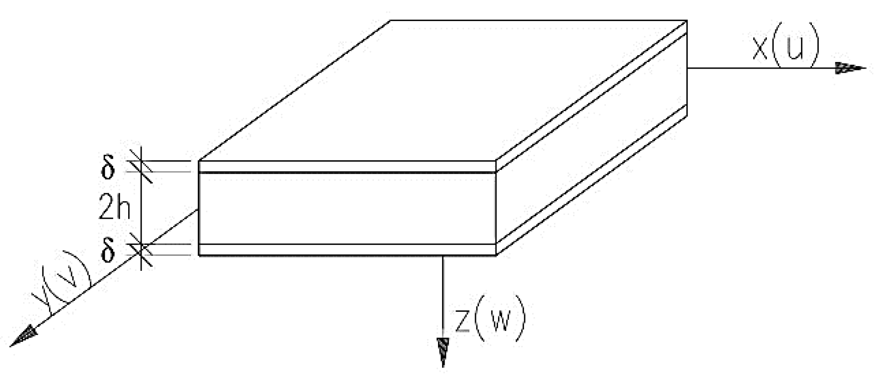
2.1. Basic Assumptions

In the work, the Hoff model was adopted for the detailed solution, the assumptions of which are as follows: (1) the plate consists of three layers and is symmetrical in relation to the middle plane (Figure 1); (2) the material of the middle layer is non-deformable in the vertical direction, and (3) the outer layers fulfill all the assumptions of the theory of thin isotropic plates and shields.
The assumptions of Hoff’s model can be described with three displacements: u(x, y) in the middle plane of the lower layer in the x-axis direction, v(x, y) in the middle plane of the lower layer in the y-axis direction, and w(x, y) as a vertical deflection of the plate, which is the same for all layers. The equilibrium equations, taken from work [32], take the form (1)–(3):
[ D 1 ν 2 E δ 2 2 ( 1 ν 2 ) G w ( 2 h + δ ) 2 4 E δ h 2 ] w ( 1 ν 2 ) G w ( 2 h + δ ) 2 E δ h · u x ( 1 ν 2 ) G w ( 2 h + δ ) 2 E δ h · v y = q 1 ν 2 2 E δ ,
( 1 ν 2 ) G w ( 2 h + δ ) 2 E δ h · w x + [ x 2 + 1 ν 2 · 2 y 2 ( 1 ν 2 ) G w E δ h ] u + 1 + ν 2 · 2 v x y = 0
( 1 ν 2 ) G w ( 2 h + δ ) 2 E δ h · w y + 1 + ν 2 · 2 u x y + [ y 2 + 1 ν 2 · 2 x 2 ( 1 ν 2 ) G w E δ h ] v = 0 ,
where E is the Young’s modulus, ν is Poisson’s ratio of materials of the outer plates, G w is the modulus of shear deformation of the middle layer, 2 h is the thickness of the middle layer, δ   is the thickness of external layers, u ,   w ,   a n d   v are plate displacements, D is the plate’s stiffness of the outer layer, which can be computed as follows: D = E δ 3 / 12 ( 1 v 2 ) .

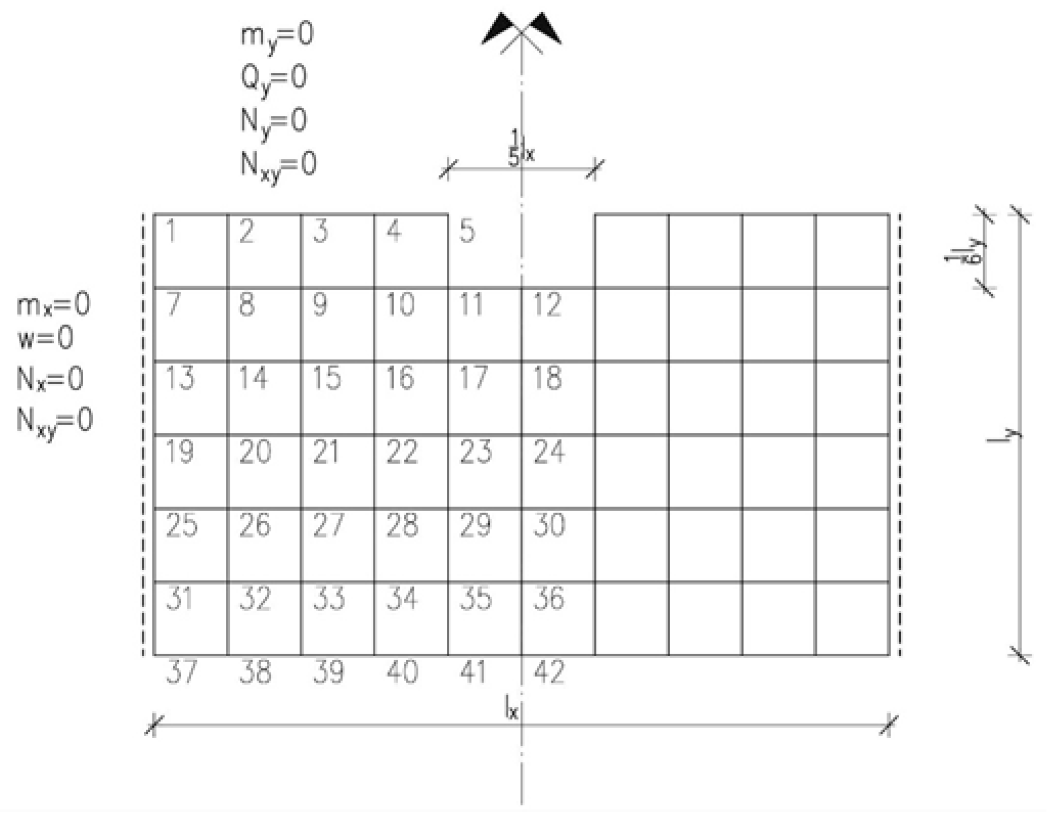
2.2. Finite Difference in Variational Form

The finite difference method was used to solve certain differential equation systems. Although it is a less frequently used method, it can be successfully used for static calculations alongside the finite element method. In the literature, there are a number of fundamental works on the method of finite differences [42,43,44,45,46,47,48,49,50,51,52,53,54,55,56]. The method is used in the calculations of plate structures [19,57,58], tanks [59,60,61,62], and surface girders. It has been used and tested many times and gives satisfactory results in the theory of coatings and thin plates.
The discretization of solutions for sandwich panels using the finite difference method in terms of variation consists of determining the minimum function of the elastic deformation energy of a bent three-layer panel. This function takes the form of (4) [1]:
V = 1 2 A { 2 D [ ( 2 w x 2 ) 2 + 2 v 2 w x 2 2 w y 2 + ( 2 w y 2 ) 2 + 2 ( 1 v ) ( 2 w x y ) 2 ] + 2 E δ 1 v 2 [ ( u x ) 2 + 2 v u x v y + 1 v 2 ( u y ) 2 + ( 1 v ) u y v x + 1 v 2 ( v x ) 2 + ( v y ) 2 ] + 2 h G w [ u 2 h 2 + 2 u h 2 h + δ 2 h w x + ( 2 h + δ ) 2 4 h 4 ( w x ) 2 + v 2 h 2 + 2 v h 2 h + δ 2 h w y + ( 2 h + δ ) 2 4 h 4 ( w y ) 2 ] } d x d y A ( q z w + q x u + q y v ) d x d y .
The derivatives in Equation (4) have been replaced with the appropriate differential schemes given e.g., in [7]. Through numerical integration, Function V was obtained as a function of several variables (5).
V = V ( w i k , u i k , v i k ) ,
where w i k ,   u i k ,   a n d   v i k are components of the displacement vector in individual nodes of the adopted partition grid.
The necessary condition for the existence of an extreme of functions of several variables is (6):
V w i k = 0 , V u i k = 0 , V v i k = 0 .
The sought displacements in the nodes of the grid are shown in Equation (5) in a quadratic form. From the dependence of (6), a symmetrical system of algebraic linear equations is obtained in order to determine the displacements, in which the number of equations is equal to the number of unknowns.
The boundary conditions known from the theory of thin plates, such as a free edge, freely supported, or fixed, are difficult to transfer to sandwich panels due to ambiguity. In work [8], using the calculus of variations, it was shown that there are sixteen homogeneous natural boundary conditions for the three-layer Hoff model discussed in this work.
The advantage of the finite difference method in the variational approach is that in the assumed system of unknowns, only the geometric boundary conditions should be met, and the static conditions are met naturally by the function itself. To write the second derivative of the deflection function w ( x ,   y ) in the finite difference method for the boundary point, it is necessary to extend beyond the edge by one interval of the partition grid, while for the first derivatives of u ( x ,   y ) and v ( x ,   y ) it is not necessary. Analyzing the natural boundary conditions for the case of the free edge of a three-layer plate, where all displacements w ,   u ,   a n d   v can occur, calculating the derivative of Function (5) with respect to the deflection at the point beyond the edge ( w i ,   k + 1 ) Equation (7) was obtained.
0.5 D s 2 ( w i , k 1 2 w i , k + w i , k + 1 ) = 0 .
Assuming Poisson’s ratio ν = 0 , we obtain m y = 0 . For the purposes of this study, the Poisson’s ratio was adopted ν = 0 in order to provide a more general and material-independent solution. Then, by calculating the derivative of Function (5) with respect to the displacements w i k ,   u i k ,   a n d   v i k , Equations (8)–(10) were obtained:
2 D s ( 3 w y 3 + 2 3 w x 2 y ) + s [ G w ( 2 h + δ ) h v + G w ( 2 h + δ ) 2 2 h · w y ] + s 2 ( D 4 w x 4 0 , 5 G w ( 2 h + δ ) h · u x 0 , 5 q ) = 0 ,
E δ s ( v x + u y ) + 0 , 5 s 2 [ G w ( 2 h + δ ) h · w x 2 E δ 2 u x 2 + 2 G w h u ] = 0 ,
2 D δ s v y s 2 [ 0 , 5 E δ 2 u x y + 0 , 5 E δ 2 v x 2 G w h v 0 , 5 G w ( 2 h + δ ) h · w y = 0 .
Assuming the relationship between displacements and cross-sectional forces, Equations (11)–(13) were obtained after minor transformations.
2 q y + N y z + s [ D 4 w x 4 0 , 5 G w ( 2 h + δ ) h · u x 0 , 5 q ] = 0 ,
N x y + 0 , 25 s [ G w ( 2 h + δ ) h · w x 2 E δ 2 u x 2 + 2 G w h u ] = 0 ,
N y 0 , 125 s [ 2 E δ 2 u x y + 2 E δ 2 v x 2 4 G w h v 2 G w ( 2 h + δ ) h · w y ] = 0 .
Taking into account Equations (1)–(3) and the dependence 2 q y + N y z = Q y , Equations (11)–(13) can be given in the form (14)–(16).
Q y + G w ( 2 h + δ ) 2 h s [ 2 h + δ 2 · 2 w x 2 + v y ] = 0 ,
N x y + 0 , 25 s [ 2 u y 2 + 2 v x y ] = 0 ,
N y + 0 , 25 E δ s 2 u x y = 0 .
If the order of magnitude s is omitted from Equations (14)–(16), these equations pass into typical boundary conditions, which can be represented by the dependencies of the assumed free edge (17) [1].
m y = 0 ,   Q y = 0 ,         N y = 0 ,   N x y = 0

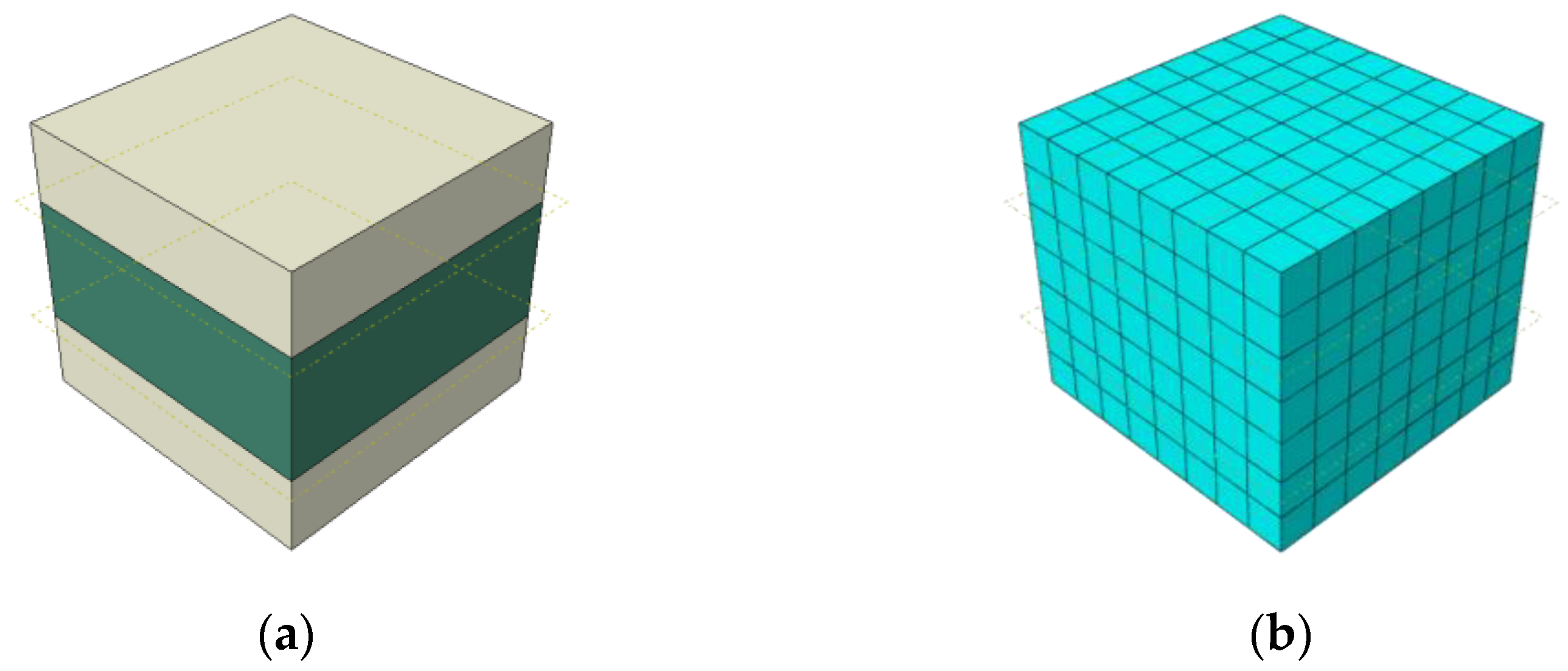
2.3. Numerical Homogenization
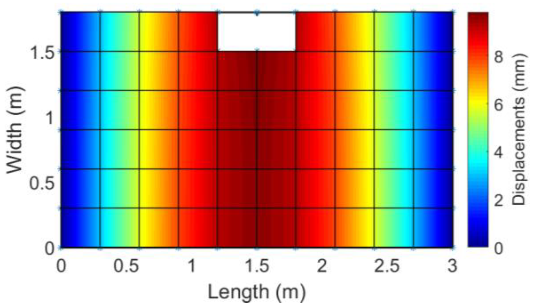
The second part of the calculation was performed based on the principles of numerical homogenization. Based on the energy equivalence between the simplified shell model and the full three-dimensional, the finite element model can be represented by an appropriate definition of displacements at the outer RVE nodes for both membrane and bending behavior. The generalized displacements at each node on the RVE surface are related to the generalized strains. Therefore, the relationship between the generalized constant strains and the position of the external nodes on the RVE boundary is expressed by the following transformation:
u i = A i   ϵ i ,
where u is the node displacement vector, and ϵ is the strain vector. Here, for a single node ( x i = x , y i = y , and z i = z ) one can derive the A i matrix adopted for the RVE model.
[ u x u y u z ] i = [ x 0 y / 2 z / 2 0 x z 0 y z / 2 0 y x / 2 0 z / 2 0 y z x z / 2 0 0 0 x / 2 y / 2 x 2 / 2 y 2 / 2 x y / 2 ] i [ ε x ε y γ x y γ x z γ y z κ x κ y κ x y ] i
Matrix A i determines the relationship between the displacements and effective deformations that are applied to nodes in boundary conditions to which the stiffness of the entire model is condensed. The total energy of elastic deformation is:
E = 1 2 u e T   K   u e = 1 2 ϵ e T   A e T   K   A e   ϵ e ,
where K is the global stiffness matrix. Taking into account that the finite element model is subjected to bending, tension, and transverse shear for the shell (or plate). The internal energy is:
E = 1 2 ϵ e T   A k   ϵ e { a r e a }
The stiffness matrix of a homogenized composite is easy to extract from a discrete matrix because:
A k = A e T   K   A e a r e a .
The matrix A k is the ABDR matrix which can be saved as:
A k = [ A 3 × 3 B 3 × 3 0 B 3 × 3 D 3 × 3 0 0 0 R 2 × 2 ] .
where A contains the tensile and shear stiffnesses, B contains the combination of tension and bending stiffness, D contains the bending and torsional stiffness, and R contains the transverse shear stiffness.

3. Results

The calculations of the detailed sandwich panel were taken from [63]. The following data was adopted for the calculations: l x = 300   cm , l y = 180   cm ,   δ = 5   cm ,   2 h = 8   cm ,   E = 2.6 · 10 4   MN / m 2 ,   G w = 3   MN / m 2 . The load was assumed as evenly distributed with a value of q = 10   kN / m 2 . For a better image, the above parameters are shown in Table 1 and Table 2. Figure 2 shows the markings, the adopted partition grid, and the boundary conditions for the analyzed slab.
Using the described method of finite differences (Equations (4)–(6)), a global matrix was built to determine the displacements. A rectangular slab, simply supported on two opposite edges and two free edges, with a cut in one of the free edges, was taken as an example of a slab. Earlier, the paper described the boundary conditions for the free edge (Equations (7)–(17)) adopted for the calculations. After using the symmetry of the plate, a system of equations with 110 unknowns was obtained to solve.
In order to calculate the reference deflections, several three-dimensional models of the sandwich panel were created, defining the cross-section and material properties in different ways. Commercial FE software (ABAQUS FEA) was used for calculations. The results obtained from the 3D model were compared with the results obtained in an analytical manner and with the method of numerical homogenization. A multi-layer slab with the dimensions shown in Figure 2 was modeled as a freely supported slab. The slab consisted of concrete external cladding and a foam core. The material parameters were adopted as in the analytical approach. Boundary conditions in both 3D numerical models of a simply supported type were applied at two opposite shorter sides. The slab was loaded with a load evenly distributed over the entire surface of the slab, with a value of 10   kN / m 2 (the same as the plate shown in Figure 2).
The first model (Model 1) is a full 3D model of the plate. Its height was modeled as 18 cm and then divided into 3 parts with appropriate layer heights, i.e., 5 cm, 8 cm, and 5 cm, using partition cells. The model discretized 3D solid elements of C3D20R (20-node brick elements with three degrees of freedom in each node with a reduced integration scheme) with dimensions of 300 mm in the plane and seven elements in thickness. The second model (Model 2) was created from a combination of 3D solids and skins. The concrete surface layers were modeled as skin and the foam core as a 3D solid structure. The core was divided into solid C3D20R elements, and skins into shell elements S4R (4-node general shell with reduced integration) with dimensions of 300 mm in the plane.
The third model (called Model 3) was created analogously to Model 1. The only difference was the discretization of the model; elements of the CSS8 (continuum solid shell elements) type were used here. Another model of the plate (Model 4) was modeled as a shell element with external dimensions as given earlier. The material properties were assigned using a composite section, and the plate was meshed with S8R elements (8-node shell elements with reduced integration scheme).
In order to perform numerical homogenization, it was necessary to correctly define the stiffness matrix of a representative volume element (RVE). This RVE model was created by extracting a portion of a structure from the entire 3D model. RVE was modeled as a solid 3D construction composed of two materials with dimensions of 20 × 20 × 18 cm. The outer layers were composed of concrete, while the core was composed of foam (Figure 3a). The whole was meshed with solid C3D20R elements (Figure 3b).
Figure 4 shows the top view of the plate along with the mean value of displacements determined by the finite difference method. The maximum value of displacements in this model is 9.82 mm.
Figure 5 shows the mean displacements of the numerical full 3D model of the Hoff panel. The maximum deflection equals 10.18 mm.
On the other hand, the simplified, single-layer model of the Hoff plates is relatively easy to build. Most of the work is required to obtain the stiffness matrix of such an element. However, this is only performed once and for all. In the case of elements consisting of several materials with very different material properties (Young’s modulus and Poisson’s ratio), the shear strength has a large impact on the deflection value. For this reason, the simplified models use the orthotropic model of composite, assuming that calculated values of G 13 and G 23 are enhanced by the shear correction factor k z , which can be computed using the following formulas (24)–(39):
k z = Q 2 G ^ [ H τ ( z ) 2 G ( z ) d z ] 1 ,
where Q is a shear force:
Q = H τ ( z ) d z = G ^   γ ,
γ is the shear strain and G ^ being the shear stiffness integrated through the plate thickness:
G ^ = H G ( z ) d z ,
τ being the shear stress:
τ ( z ) = Q D ^ F ( z ) ,
where D ^ is defined as:
D ^ = A D B 2 .
In Equation (28), the tensile-compressive stiffness ( A ), flexural stiffness ( D ), and the coupling stiffness ( B ) can be extracted from the matrix A k . In case of isotropic layered plates A = A 11 = A 22 , B = B 11 = B 22 , D = D 11 = D 22 (see Equation (23)). All stiffnesses can be also computed using the CLPT theory, so the tensile-compressive stiffness reads:
A = H E ( z ) d z = i = 1 M ( z i + 1 z i ) E i ,
while coupling stiffness takes a form:
B = H E ( z ) z   d z = 1 2 i = 1 M ( z i + 1 2 z i 2 ) E i ,
and the flexural stiffness is:
D = H E ( z ) z 2 d z = 1 3 i = 1 M ( z i + 1 3 z i 3 ) E i ;
where E i is the Young’s modulus of the i-th layer, while z i and z i + 1 are distances from the neutral plane to i-th layer (see Figure 6).
In the Equation (27) the function F ( z ) has a form:
F ( z ) = A S ( z ) + B P ( z ) ,
where
S ( z ) = ( h + δ ) z z E ( z ) d z ,
and
P ( z ) = ( h + δ ) z E ( z ) d z .
In both the above equations h is the bottommost fiber location (see Figure 6). For the layered plates, Equations (33) and (34) can be separated into two cases: (a) when the integral is defined in the bottommost layer. The function S ( z ) reads:
S 1 ( z ) = ( z 2 ( h + δ ) 2 ) 1 2 E 1
while the function P ( z ) takes the form:
P 1 ( z ) = ( z ( h + δ ) ) E 1 ,
and case (b), when integrals are defined in the i-th layer ( i > 1 ), where S ( x ) becomes:
S i ( z ) = 1 2 ( k = 1 i ( z k + 1 2 z k 2 ) E k + ( z 2 z i 2 ) E i ) .
and P ( x ) is:
P i ( z ) = k = 1 i ( z k + 1 z k ) E k + ( z z i ) E i .
Finally, the shear correction factor for layered concrete plate takes the form:
k z = D ^ 2 G ^ [ z 1 z 2 ( A S 1 ( z ) + B P 1 ( z ) ) 2 G 1 d z + i = 2 z i z i + 1 ( A S i ( z ) + B P i ( z ) ) 2 G i d z ] 1 ,
which in the case of the analyzed example gives the value of k z equals 0.007. It is worth noting that this coefficient is completely different from the shear correction coefficient, which for a homogeneous rectangular section is 5/6. Another important observation is the fact that, in the case of symmetrical homogeneous plates, the neutral axis coincides with the geometric axis, and therefore, the coupling stiffness B vanishes.
In the case of Hoff’s plates, the stiffness matrix was obtained from the homogenization process and the classical laminated plate theory (CLPT) method. The stiffness matrices (taking into account only the symmetrical part) obtained from the two methods are presented in Table 3.
The maximum deflection values obtained from various numerical models and the analytical methods are presented in Table 4.
To better visualize the behavior of the plate, displacement diagrams for each model are presented. Figure 7 shows the displacements of the Hoff’s panel cut parallel to its length in the middle of the width.
The values given in Table 4 and in Figure 4 and Figure 5 indicate the correctness of the adopted numerical methods. The compliance of the obtained results is satisfactory.
To better illustrate the comparative analysis of the methods, Table 5 shows some values of the cross-sectional forces determined using the finite difference method and the simplified numerical homogenization method. The table presents the bending moment in the claddings (mx) and the bending moment for the entire slab cross-section (Mx) at the selected points.

4. Discussion

The paper presents several methods for calculating the deformation of a three-layer Hoff’s plate. In the first case, the finite difference method in the variational approach was used. In the second case, the numerical FE model was used, and in the third case, the homogenization method enhanced with an analytically computed shear correction factor was used. The correctness of the calculations using the finite difference method has been confirmed in numerous computational scientific works, as well as being confirmed by model tests.
Work [19] presents the results of the differential calculations of a slab of variable thickness. The obtained results were verified with model tests composed of resin and subjected to thermal loads. The compliance of the results of the calculations and model tests confirms the correctness of the determined matrix and systems of equations in accordance with the finite difference method. The effect of temperature is often neglected when calculating plate structures, and yet it gives moment values greater than in the case of other loads. The bending moments due to the applied thermal load increase in direct proportion to the square of the wall thickness.
Work in [57] concerns the calculation of a floor slab with a static scheme of a slab with free edges loaded in bands along the perimeter of the slab, resting on a Winkler elastic foundation. The calculations were performed for two variants, taking into account two values of the subsoil stiffness modulus. It was indicated in the paper that taking into account the influence of the thermal insulation layer composed of spray-applied polyurethane foam in the calculations of the slab causes an increase in the substrate compliance modulus and deflection, and the bending moments decrease. The obtained results show the necessity to calculate the floor as a layered element.
Paper [59] presents the results of verification of the static calculations of a monolithic rectangular tank with walls with a trapezoidal cross-section. Static calculations were performed with the use of a computer program based on the finite element method (FEM) as well as the finite difference method (FDM) in terms of energy (taking into account the spatial static operation of the tank). The verification of the obtained results was carried out on a concrete tank model with the use of a modern measuring tool: a coordinate measuring arm with a contact head. The compliance of the obtained results proves the correctness of the adopted calculation methods, i.e., the finite element method, on the basis of which the calculations with Autodesk Robot Structural Analysis Professional were performed, and the finite difference method in terms of energy, with the use of which the calculations were carried out traditionally.
Work [62] concerns the cooperation between the tank walls and the polystyrene filling treated as a Winkler-type elastic substrate, assuming the Poisson’s ratio of ν = 0 . Taking into account the cooperation of the walls of the tank with the elastic foundation filling, the tank in the calculations reduces the bending moments and, in some cases, changes the sign of the bending moments.
Work [64] presents solutions for a three-dimensional plate strand that shows a high agreement in comparison with the values from Table 3 and Table 4 for the differential solution, assuming specific geometrical and material parameters. It has been shown in [65] that for a three-layer plate strip at G w , plate deflections tend to deflect isotropic plates with the stiffness D z corresponding to the stiffness of two plates with a thickness of δ separated by 2 h . As the G w modulus increases, the deflections and normal stresses in the claddings decrease, while the shear stresses in the core increase [63].
In [66], a number of numerical solutions for sandwich structures were given, along with the results of experimental tests. Among others, examples of sandwich panels with metal cladding are given. The share of the core in carrying the load is very small and can be neglected. This is due to the fact that the ratio of the Young’s modulus of the mantle to the Young’s modulus of the core reaches several thousand. The relationships given in the paper show that the load acting in the plane of the slab will be transferred almost entirely by the cladding. The core, on the other hand, transfers the stresses resulting from shear. Its role in this case is to keep the linings at a constant mutual distance. Another advantage of multi-layer composite structures with respect to homogeneous ones is given by vibration reduction via damping increase. In particular, the damping behavior of multi-layer composites is due to the local dissipation mechanism acting at the interface between any two different layers. This problem is discussed in many publications, e.g., [67,68,69].
In the present study, the results obtained from the simplified models by the homogenization method and the CLPT method are consistent with the results of the 3D models, which were obtained by various methods of plate modeling and the analytical method. The application of the orthotropic material model of concrete, where the shear stiffness G13 and G23 were reduced 1000 times, had a large impact on the results of deflections for the simplified models. This approach was used because in models with different materials with differences in several thousand material parameters, the shear capacity has a significant impact on the deflection. The work additionally shows that the use of the simplest shell composite models does not work for models consisting of layers with very different material parameters. The value of the obtained deflections significantly differs by approximately 70% compared to the other models.

5. Conclusions

The calculation results presented in the paper were obtained using the finite difference method in the variational approach, assuming the Poisson’s ratio ν = 0 for a sandwich, rectangular slab, simply supported on two opposite edges, and two free edges with a cut in one of the free edges. Analogous calculations were performed using a simplified model with a substitute plate stiffness, transforming the sandwich panel into a homogeneous structure. Based on the comparative analysis, it can be concluded that: (a) the method of variational approach to finite differences, used in the theory of isotropic plates and the theory of shells, is suitable for solving three-layer plates. Compared to the finite element method, the systems of equations are smaller. In energy terms, the difference operators have a lower order. This affects the speed of calculations during parametric analysis and the optimization of calculations; and (b) the performed calculations using FEM and homogenized sandwich plate enhanced with an analytically computed shear correction factor, showed that the results were compatible with FDM. This proves that the use of simplified calculation methods not only speeds up the computation but is fully justified in terms of accuracy.

Author Contributions

Conceptualization, A.S.-G. and T.G.; methodology, A.S.-G. and T.G.; software, N.S., A.S.-G. and T.G.; validation, N.S., A.S.-G. and T.G.; formal analysis, N.S. and A.S.-G.; investigation, N.S. and A.S.-G.; resources, N.S. and A.S.-G.; data curation, N.S.; writing—original draft preparation, N.S. and A.S.-G.; writing—review and editing, T.G.; visualization, N.S., A.S.-G. and T.G.; supervision, T.G. and A.S.-G.; project administration, T.G.; funding acquisition, T.G. All authors have read and agreed to the published version of the manuscript.

Funding

This research received no external funding.

Institutional Review Board Statement

Not applicable.

Informed Consent Statement

Not applicable.

Data Availability Statement

The data presented in this study are available on request from the corresponding author.

Conflicts of Interest

The authors declare no conflict of interest.

References

  1. Buczkowski, W. Numerical analysis of sandwich panels (in polish). Arch. Civ. Eng. 1981, 27, 51–61. [Google Scholar]
  2. Birman, V.; Kardomateas, G.A. Review of current trends in research and applications of sandwich structures. Compos. Part B: Eng. 2018, 142, 221–240. [Google Scholar] [CrossRef]
  3. Hause, T.J. Sandwich Structures: Theory and Responses; Springer: Cham, Switzerland, 2021; pp. 1–3. [Google Scholar]
  4. Altenbach, H.; Altenbach, J.; Kissing, W. Mechanics of Composite Structural Elements, 2nd ed.; Springer Nature: Singapore, 2018; p. 503. [Google Scholar]
  5. Zhang, J.; Yan, Z.; Xia, L. Vibration and Flutter of a Honeycomb Sandwich Plate with Zero Poisson’s Ratio. Mathematics 2021, 9, 2528. [Google Scholar] [CrossRef]
  6. Lu, C.; Zhao, M.; Jie, L.; Wang, J.; Gao, Y.; Cui, X.; Chen, P. Stress Distribution on Composite Honeycomb Sandwich Structure Suffered from Bending Load. Procedia Eng. 2015, 99, 405–412. [Google Scholar] [CrossRef] [Green Version]
  7. Szekrényes, A. Analytical solution of some delamination scenarios in thick structural sandwich plates. J. Sandw. Struct. Mater. 2017, 21, 1271–1315. [Google Scholar] [CrossRef] [Green Version]
  8. Burlayenko, V.N.; Sadowski, T.; Dimitrova, S. Three-Dimensional Free Vibration Analysis of Thermally Loaded FGM Sandwich Plates. Materials 2019, 12, 2377. [Google Scholar] [CrossRef] [Green Version]
  9. Garg, A.; Belarbi, M.-O.; Chalak, H.; Chakrabarti, A. A review of the analysis of sandwich FGM structures. Compos. Struct. 2020, 258, 113427. [Google Scholar] [CrossRef]
  10. Jha, D.K.; Kant, T.; Singh, R.K. A critical review of recent research on functionally graded plates. Compos. Struct. 2013, 96, 833–849. [Google Scholar] [CrossRef]
  11. Thai, H.-T.; Kim, S.-E. A review of theories for the modeling and analysis of functionally graded plates and shells. Compos. Struct. 2015, 128, 70–86. [Google Scholar] [CrossRef]
  12. Daniel, I.M. Composite Materials, Chapter 19 in Handbook on Experimental Mechanics; Oxford University Press: New York, NY, USA, 2006. [Google Scholar]
  13. Katouzian, M.; Vlase, S.; Calin, M.R. Experimental procedures to determine the viscoelastic parameters of laminated composites. J. Optoelectron. Adv. Mater. 2011, 13, 1185–1188. [Google Scholar]
  14. Motoc, D.L.; Vlase, S. Micromechanical based simulation and experimental approaches in the thermal conductivities assessment of hybrid polymeric composite materials. In Proceedings of the ASME 11th Biennial Conference on Engineering Systems Design and Analysis, Nantes, France, 2–4 July 2012; pp. 21–26. [Google Scholar]
  15. Suemasu, H. Effects of Multiple Delaminations on Compressive Buckling Behaviors of Composite Panels. J. Compos. Mater. 1993, 27, 1172–1192. [Google Scholar] [CrossRef]
  16. Li, D.; Zhu, H.; Gong, X. Buckling Analysis of Functionally Graded Sandwich Plates under Both Mechanical and Thermal Loads. Materials 2021, 14, 7194. [Google Scholar] [CrossRef] [PubMed]
  17. Adhikari, B.; Dash, P.; Singh, B. Buckling analysis of porous FGM sandwich plates under various types nonuniform edge compression based on higher order shear deformation theory. Compos. Struct. 2020, 251, 112597. [Google Scholar] [CrossRef]
  18. Rezaiee-Pajand, M.; Arabi, E.; Masoodi, A.R. Nonlinear analysis of FG-sandwich plates and shells. Aerosp. Sci. Technol. 2019, 87, 178–189. [Google Scholar] [CrossRef]
  19. Szymczak-Graczyk, A. Rectangular Plates of a Trapezoidal Cross-Section Subjected to Thermal Load. IOP Conf. Ser. Mater. Sci. Eng. 2019, 603, 032095. [Google Scholar] [CrossRef]
  20. Jalali, S.; Naei, M.; Poorsolhjouy, A. Thermal stability analysis of circular functionally graded sandwich plates of variable thickness using pseudo-spectral method. Mater. Des. 2010, 31, 4755–4763. [Google Scholar] [CrossRef]
  21. Kiani, Y.; Bagherizadeh, E.; Eslami, M.R. Thermal and mechanical buckling of sandwich plates with FGM face sheets resting on the Pasternak elastic foundation. Proc. Inst. Mech. Eng. Part C: J. Mech. Eng. Sci. 2011, 226, 32–41. [Google Scholar] [CrossRef]
  22. Van Do, V.N.; Lee, C.-H. Thermal buckling analyses of FGM sandwich plates using the improved radial point interpolation mesh-free method. Compos. Struct. 2017, 177, 171–186. [Google Scholar] [CrossRef]
  23. Swaminathan, K.; Sangeetha, D. Thermal analysis of FGM plates—A critical review of various modeling techniques and solution methods. Compos. Struct. 2017, 160, 43–60. [Google Scholar] [CrossRef]
  24. Burlayenko, V.N. Modelling Thermal Shock in Functionally Graded Plates with Finite Element Method. Adv. Mater. Sci. Eng. 2016, 2016, 7514638. [Google Scholar] [CrossRef] [Green Version]
  25. Do, T.; Bui, T.; Yu, T.; Pham, D.; Nguyen, C. Role of material combination and new results of mechanical behavior for FG sandwich plates in thermal environment. J. Comput. Sci. 2017, 21, 164–181. [Google Scholar] [CrossRef]
  26. Itu, C.; Öchsner, A.; Vlase, S.; Marin, M.I. Improved rigidity of composite circular plates through radial ribs. Proc. Inst. Mech. Eng. Part L J. Mater. Des. Appl. 2018, 233, 1585–1593. [Google Scholar] [CrossRef]
  27. Pendleton, R.L.; Tutle, M.E. Manual of Experimental Methods for Mechanical Testing of Composites; Springer Science & Business Media: Berlin, Germany, 2012. [Google Scholar]
  28. Itu, C.; Vlase, S.; Scutaru, M.L.; Modrea, A. Bending behavior of a high rigidity plate made by a composite panel. Procedia Manuf. 2019, 32, 144–150. [Google Scholar] [CrossRef]
  29. Scutaru, M.L.; Itu, C.; Marin, M.; Grif, H. Bending Tests Used to Determine the Mechanical Properties of the Components of a Composite Sandwich Used in Civil Engineering. Procedia Manuf. 2019, 32, 259–267. [Google Scholar] [CrossRef]
  30. Hoff, N.J. Bending and Buckling of Rectangular Sandwich Plates; NACA: Washington, DC, USA, 1950. [Google Scholar]
  31. Wachowiak, J.; Wilde, P. Wolnopodparte prostokątne płyty trójwarstwowe. Arch. Inżynierii Lądowej 1966, 22, 71–90. [Google Scholar]
  32. Mikołajczak, H. Zagadnienia Nieciągłych Warunków Brzegowych dla Prostokątnych Płyt Trójwymiarowych; Roczniki WSR: Poznań, Poland, 1965. [Google Scholar]
  33. Staszak, N.; Garbowski, T.; Szymczak-Graczyk, A. Solid Truss to Shell Numerical Homogenization of Prefabricated Composite Slabs. Materials 2021, 14, 4120. [Google Scholar] [CrossRef]
  34. Buannic, N.; Cartraud, P.; Quesnel, T. Homogenization of corrugated core sandwich panels. Compos. Struct. 2003, 59, 299–312. [Google Scholar] [CrossRef] [Green Version]
  35. Ramírez-Torres, A.; Penta, R.; Rodríguez-Ramos, R.; Grillo, A. Effective properties of hierarchical fiber-reinforced composites via a three-scale asymptotic homogenization approach. Math. Mech. Solids 2019, 24, 3554–3574. [Google Scholar] [CrossRef]
  36. Garbowski, T.; Marek, A. Homogenization of corrugated boards through inverse analysis. In Proceedings of the 1st International Conference on Engineering and Applied Sciences Optimization, Kos Island, Greece, 4–6 June 2014; pp. 1751–1766. [Google Scholar]
  37. Hohe, J. A direct homogenisation approach for determination of the stiffness matrix for microheterogeneous plates with application to sandwich panels. Compos. Part B Eng. 2003, 34, 615–626. [Google Scholar] [CrossRef]
  38. Biancolini, M.E. Evaluation of equivalent stiffness properties of corrugated board. Comp. Struct. 2005, 69, 322–328. [Google Scholar] [CrossRef]
  39. Garbowski, T.; Gajewski, T. Determination of Transverse Shear Stiffness of Sandwich Panels with a Corrugated Core by Numerical Homogenization. Materials 2021, 14, 1976. [Google Scholar] [CrossRef] [PubMed]
  40. Garbowski, T.; Knitter-Piątkowska, A.; Mrówczyński, D. Numerical Homogenization of Multi-Layered Corrugated Cardboard with Creasing or Perforation. Materials 2021, 14, 3786. [Google Scholar] [CrossRef] [PubMed]
  41. Staszak, N.; Gajewski, T.; Garbowski, T. Shell-to-Beam Numerical Homogenization of 3D Thin-Walled Perforated Beams. Materials 2022, 15, 1827. [Google Scholar] [CrossRef]
  42. Kączkowski, Z. Plates. Static Calculations; Arkady: Warsaw, Poland, 2000. [Google Scholar]
  43. Gołaś, J. Pewne rozwiązania dla kołowych płyt trójwarstwowych obciążonych na krawędzi. Rozpr. Inżynierskie 1971, 19, 275–286. [Google Scholar]
  44. Donnell, L.H. Beams, Plates and Shells; McGraw-Hill: New York, NY, USA, 1976. [Google Scholar]
  45. Naghdi, P.M. The Theory of Shells and Plates; Handbuch der Physick: Berlin, Germany, 1972. [Google Scholar]
  46. Panc, V. Theories of Elastic Plates; Academia: Prague, Czech Republic, 1975. [Google Scholar]
  47. Timoshenko, S.; Woinowsky-Krieger, S. Theory of Plates and Coatings; Arkady: Warsaw, Poland, 1962. [Google Scholar]
  48. Szlilard, R. Theory and Analysis of Plates. Classical and Numerical Methods; Prentice Hall, Englewood Cliffs: Bergen, NJ, USA; Prentice-Hall: Upper Saddle River, NJ, USA, 1974. [Google Scholar]
  49. Ugural, A.C. Stresses in Plates and Shells; McGraw-Hill: New York, NY, USA, 1981. [Google Scholar]
  50. Wilde, P. Variational approach of finite differences in the theory of plate. In Proceedings of the Materials of XII Scientific Conference of the Committee of Science PZiTB and the Committee of Civil Engineering of Polish Academy of Sciences, Krynica, Poland, 12–17 September 1966. [Google Scholar]
  51. Tribiłło, R. Application of the generalized finite difference method for plate calculations. Arch. Inżynierii Lądowej 1975, 2, 579–586. [Google Scholar]
  52. Son, M.; Jung, H.S.; Yoon, H.H.; Sung, D.; Kim, J.S. Numerical Study on Scale Effect of Repetitive Plate-Loading Test. Appl. Sci. 2019, 9, 4442. [Google Scholar] [CrossRef] [Green Version]
  53. Nowacki, W. From the application of the calculus of finite differences in structure mechanics. Arch. Mech. Stos. 1951, 3, 419–435. (In Polish) [Google Scholar]
  54. Rapp, B.E. Finite Difference Method, Chapter 30 in Microfluidics: Modelling, Mechanics and Mathematics, Micro and Nano Technologies; Rapp, B.E., Ed.; Elsevier: Amsterdam, The Netherlands, 2017; pp. 623–631. [Google Scholar] [CrossRef]
  55. Blazek, J. Principles of Solution of the Governing Equations, Chapter 3 in Computational Fluid Dynamics: Principles and Applications; Blazek, J., Ed.; Elsevier: Amsterdam, The Netherlands, 2015; pp. 29–72. [Google Scholar] [CrossRef]
  56. Sadd, M.H. Formulation and Solution Strategies, Chapter 5 in Elasticity, Theory, Applications, and Numerics; Sadd, M.H., Ed.; Academic Press; Elsevier: Cambridge, MA, USA, 2005; pp. 83–102. [Google Scholar] [CrossRef]
  57. Szymczak-Graczyk, A. Numerical Analysis of the Impact of Thermal Spray Insulation Solutions on Floor Loading. Appl. Sci. 2020, 10, 1016. [Google Scholar] [CrossRef] [Green Version]
  58. Numayr, K.S.; Haddad, R.H.; Haddad, M.A. Free vibration of composite plates using the finite difference method. Thin-Walled Struct. 2004, 42, 399–414. [Google Scholar] [CrossRef]
  59. Buczkowski, W.; Szymczak-Graczyk, A.; Walczak, Z. Experimental validation of numerical static calculations for a monolithic rectangular tank with walls of trapezoidal cross-section. Bull. Pol. Acad. Sci. Technol. Sci. 2017, 65, 799–804. [Google Scholar] [CrossRef] [Green Version]
  60. Szymczak-Graczyk, A. Floating platforms made of monolithic closed rectangular tanks. Bull. Pol. Acad. Sci. Technol. Sci. 2018, 66, 209–216. [Google Scholar] [CrossRef]
  61. Szymczak-Graczyk, A. Numerical Analysis of the Bottom Thickness of Closed Rectangular Tanks Used as Pontoons. Appl. Sci. 2020, 10, 8082. [Google Scholar] [CrossRef]
  62. Szymczak-Graczyk, A. The Effect of Subgrade Coefficient on Static Work of a Pontoon Made as a Monolithic Closed Tank. Appl. Sci. 2021, 11, 4259. [Google Scholar] [CrossRef]
  63. Buczkowski, W. Numerical Calculation of Three-Layer Panels Used in Agricultural Construction. Ph.D. Thesis, Institute of Water and Melioration Construction. Agricultural University in Poznań, Poznań, Poland, 1977. (In Polish). [Google Scholar]
  64. Mikołajczak, H.; Buczkowski, W.; Łęcki, W.; Wosiewicz, B. Three-layer ceiling slabs for livestock buildings. Ann. Agric. Univ. 1975, 77, 43–52. (In Polish) [Google Scholar]
  65. Mikołajczak, H. Asymptotic solution for a three-layer plate strand (in polish). Sci. Pap. Gdańsk Univ. Technol. 1977, 31, 169–175. [Google Scholar]
  66. Romanow, F.; Stricker, L.; Teisseyre, J. Stability of Sandwich Structures (In Poilsh); Publishing House of the Wrocław University of Technology: Wrocław, Poland, 1972. [Google Scholar]
  67. Catania, G.; Strozzi, M. Damping Oriented Design of Thin-Walled Mechanical Components by Means of Multi-Layer Coating Technology. Coatings 2018, 8, 73. [Google Scholar] [CrossRef] [Green Version]
  68. Yu, L.; Ma, Y.; Zhou, C.; Xu, H. Damping efficiency of the coating structure. Int. J. Solids Struct. 2005, 42, 3045–3058. [Google Scholar] [CrossRef]
  69. Zhang, X.; Wu, R.; Li, X.; Guo, Z.X. Damping behaviors of metal matrix composites with interface layer. Sci. China Ser. E-Technol. Sci. 2001, 44, 640–646. [Google Scholar] [CrossRef]
Figure 1. Plate of the Hoff model (w–out of plane displacement, u and v–in plane displacements).
Applsci 12 09918 g001
Figure 2. Sandwich panel taken for calculation.
Applsci 12 09918 g002
Figure 3. RVE—(a) 3D model; (b) mesh.
Applsci 12 09918 g003
Figure 4. Mean displacements of the analytical model.
Applsci 12 09918 g004
Figure 5. Mean displacements of Model 1 (numerical full 3D model).
Applsci 12 09918 g005
Figure 6. A diagram of the displacements in the middle of the plate span.
Applsci 12 09918 g006
Figure 7. A diagram of the displacements in the middle of the plate span.
Applsci 12 09918 g007
Table 1. Geometric dimensions of the sandwich panel and applied external loads.
l x
( cm )
l y
( cm )
δ
( cm )
2 h
( cm )
q
( k N / m 2 )
3001805810
Table 2. Material parameters of the external layers and middle core.
E
( M N / m 2 )
G w
( M N / m 2 )
v
( )
External layers 2.6 × 10 4 4.33 × 10 3 0.2
Middle core630
Table 3. Stiffness matrix for plate.
StiffnessHomogenization MethodCLPT Method
A 11   ( 10 6 MPa mm)2.73592.7088
A 12   ( 10 6 MPa mm)0.56880.5417
A 22   ( 10 6 MPa mm)2.73592.7088
A 33   ( 10 6 MPa mm)1.08361.0835
D 11   ( 10 10 MPa mm)1.21251.2007
D 12   ( 10 10 MPa mm)0.25190.2401
D 22   ( 10 10 MPa mm)1.21251.2007
D 33   ( 10 10 MPa mm)0.48030.4803
R 44   ( 10 3 MPa mm)1.32031.2833
R 55   ( 10 3 MPa mm)1.32031.2833
Table 4. Maximum displacement of plate.
Name of ModelValue of Displacements (mm)
Analytical model9.82
Model 110.18
Model 29.93
Model 39.94
Model 417.43
Homogenization model9.71
CLPT model9.89
Table 5. Value of selected cross-sectional forces for the slab.
Grid Point NoFinite Difference Method in the Variational Approach [63]Numerical Homogenization
mx (Nm/m)Mx (Nm/m)mx (Nm/m)Mx (Nm/m)
12338119,550321418,753
18303614,016296313,507
24285612,134273111,834
30277711,244266310,868
36274610,619261510,054
422735986525979352
Publisher’s Note: MDPI stays neutral with regard to jurisdictional claims in published maps and institutional affiliations.

