Article

Nonthermal Plasma Multi-Reactor Scale-Up Using Pulse Capacitive Power Supplies

Faculty of Electrical Engineering, “Gheorghe Asachi” Technical University of Iasi, 700050 Iaşi, Romania
*
Author to whom correspondence should be addressed.
Appl. Sci. 2022, 12(20), 10403; https://doi.org/10.3390/app122010403
Submission received: 23 September 2022 / Revised: 12 October 2022 / Accepted: 12 October 2022 / Published: 15 October 2022

Abstract

:
The scale up of nonthermal plasma (NTP) reactors requires the simultaneous operation in parallel of a large number of units supplied from the same power supply. The present paper aims to demonstrate the feasibility of parallel operation of multiple mini-NTP reactors. In order to demonstrate the parallel operation of a large number of NTP reactors, three different types of power supplies are considered. In addition to the most simple and common solution, which involves the use of individual, independent power supply for each reactor (an ignition coil driven by a pulse generator), two other configurations of supplies (capacitive AC and capacitive DC), simpler and less expensive, are tested. The capacitive pulsed power supplies allow the generation of HV pulses by an AC power supply (usually an AC transformer), as well as by a DC power supply using an R–C circuit. For the DC resistive–capacitive configuration, the frequency can be adjusted. For all configurations, the power of the discharge can be modified by changing the value of capacitors or resistors. The feasibility of the proposed systems was demonstrated by assessing the concentration of hydrogen peroxide induced in water after plasma treatment. The obtained results reveal that the proposed capacitive AC and DC power supplies allow a large number of plasma reactors to operate in parallel independently.

1. Introduction

Nonthermal plasma technologies have been proven to be effective in the degradation of organic pollutants from air and water, as well as in biological applications or plasma-activated water (PAW) production for use in agriculture. It has been found that PAW has a positive effect on the development of plants, with the published studies referring in particular to agricultural production in greenhouses and demonstrating that irrigation with PAW leads to an increase in biological mass [1,2]. However, the large-scale use of PAW in agriculture requires the development of NTP reactor systems to provide the large, required volumes [3]. A nonthermal plasma is generated by an electrical discharge in gas that arises when a high voltage is applied between two (or more) electrodes followed by the occurrence of an avalanche electronic emission phenomenon that results in the passage of gas, which is usually insulator, in a partially ionized plasma state (nonthermal plasma; NTP). The collision of energetic electrons with neutral atomic species produces their ionization, the dissociation of molecules, and the electronic vibration of atoms, leading to reactive oxygen species (ROS). The main active atomic species, additional radicals such as hydroxyl radical (OH) and hydronium ion (H3O+), and reactive molecules such as ozone (O3), hydroperoxyl radical (HO2), and hydrogen peroxide (H2O2) are formed by excitation/recombination of water molecules, with Ar as the carrier gas [4,5,6,7,8]. Given that the reactive species responsible for the decomposition of air pollutants are highly dependent on the chemical nature of the pollutants, studies on the formation of chemical reactive species and their reaction pathways are essential to optimize the design of NTP reactors for real applications.
Most nonthermal plasma applications, such as the depollution of the water and air, the production of activated water (PAW) for applications in agriculture, and surface disinfection, require the adaptation of power supplies for the production of plasma to specific conditions of each application [9,10].
The components of saturated and unsaturated hydrocarbons are highly reactive to radical species and ozone, and they are easily decomposed in the NTP reactors [11,12,13]. In order to increase the degradation of the organic pollutant, an alternative reactor configuration has been shown to be much more effective than the treatment of water in a batch. In this alternative configuration, a small quantity of liquid is sprayed directly into the plasma generated by a pulsed high-voltage discharge of an NTP reactor with confined plasma. It was demonstrated that the treatment of polluted water or PAW production in pulsed NTP mini-reactors with spray (up to 20 mL/min water flow rate) is up to 10 times more effective than the treatment or PAW production in batch reactors [14,15].
The technological simplicity and ability to operate at atmospheric pressure and temperature [16] make NTP reactors suitable for a wide variety of industrial applications.
Another challenge of using cold plasma is to increase the volume of plasma-activated water (PAW), especially for applications in agriculture where a high volume of water is required.
The nonthermal plasma-activated water (PAW) produced by pulsed NTP spray technology [17,18,19,20] has a notable effect on plant growth and pest elimination (bio-disinfection). It was demonstrated that PAW reduces the period of plant growth, increases the biomass, and provides the disinfection of plant leaves, and it is also effective as a bio fertilizer.
One problem that limits the use of NTP electrochemical reactors to treat large amounts of water is the difficulty to upscale NTP systems. The difficulty resides in the parallel operation of a large number of NTP reactors powered by the same power supply, which requires the parallel operation of several electric discharges.
The design, development, and analysis of the possibility of upscaling the NTP chemical reactors for industrial application are of critical importance for the development of NTP technologies [21].
The main goal of the present paper is to propose three high-performance electrical schematics of pulsed power supplies for NTP generation as an alternative to classical pulsed power supplies (that usually use the rotating mechanical pulse generator) [22].

2. Experimental

The pulse power supply is designed to generate nonthermal plasma in an electrochemical reactor for different applications. The theory of operation of the presented solution consists of applying an electrical discharge, in specific physical/electrical conditions, in order to maintain the nonthermal characteristics of the plasma on the NTP reactor electrodes.
This paper proposes three schematics of HV pulse generator power supplies suitable for scaling up the NTP mini reactors to a NTP multi-reactor array, working in parallel. If we consider that a single unit of NTP reactor is optimal for a water flow rate Qi in terms of water treatment or PAW production efficiency, the total water flow rate for the n multi-reactor array is
Q t = i = 1 n Q i .

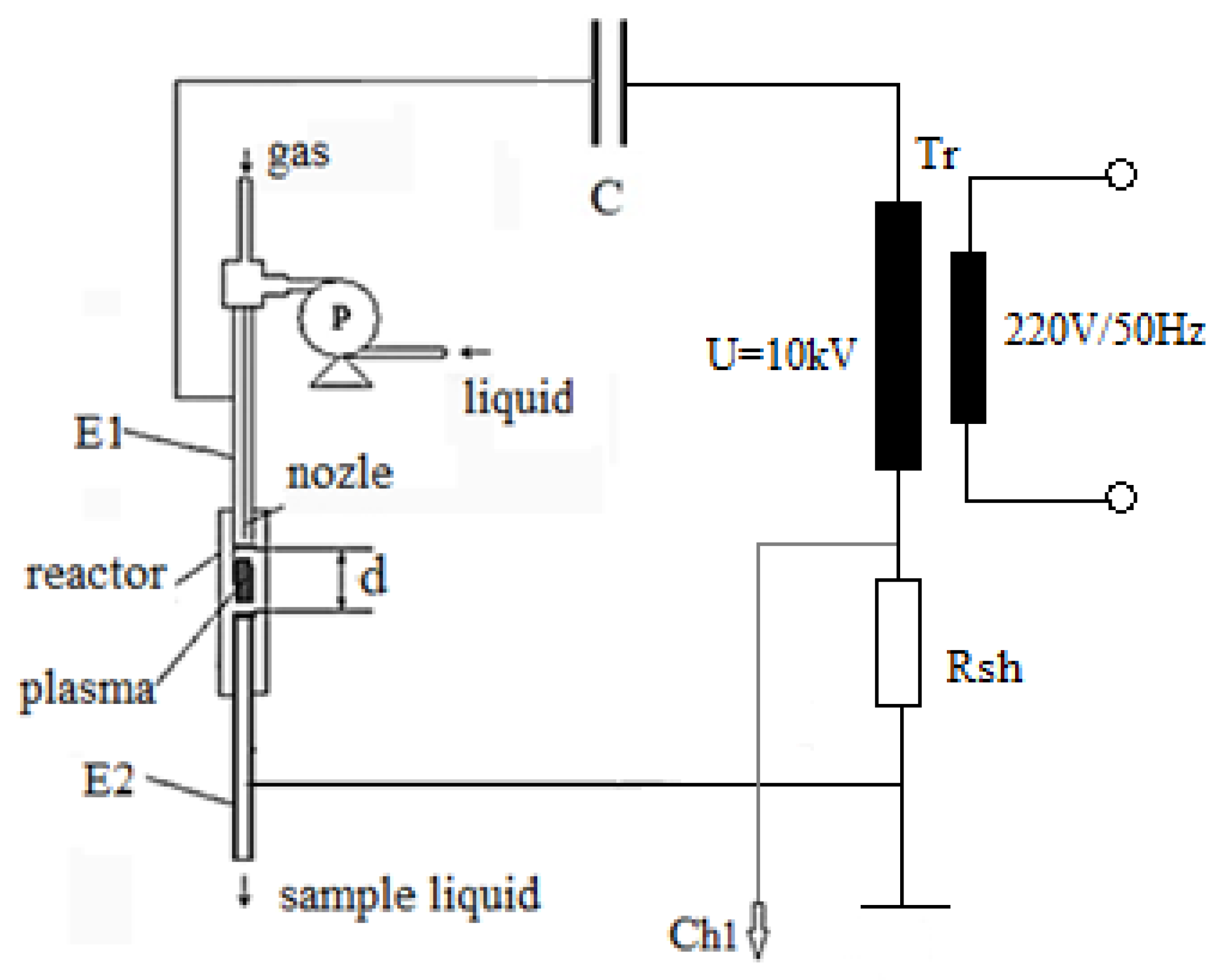
2.1. NTP Reactor Unit Powered Up by an Induction Coil-Driven Power Supply (ICR)

The schematic of the first option for the high-voltage power supply used to power up the NTP reactors array is presented in Figure 1, while Figure 2 presents typical current and voltage waveforms recorded for ignition coils to supply the electrical discharge.
The HV pulses for nonthermal plasma generation are delivered by an induction coil used in the automotive sector, driven by an IGBT transistor supplied by a DC power supply (in our case, U = 12 V). The IGBT transistor is controlled by a pulse generator with adjustable frequency and pulse duty cycle.
The proposed technical solution uses an I-shaped reactor (I-NTP) consisting of two cylindrical point-to-point stainless-steel electrodes placed into a glass cylinder, at a distance of 3 mm between them. The pulse-spray mini-reactor for water treatment/PAW production is presented in Figure 1, where P is the pump for water injected into the reactor, OSC is the oscilloscope (Lecroy Wavesurfer 454, 500 MHz, 5 GS/s), HVP is the high-voltage probe for voltage measurement (Testec TT-HVP-2739, divider 1000:1, 220 MHz), and Rsh is the shunt for current measurement (100 Ω calibrated resistor). The electrodes E1 and E2 are placed in a glass tube at 3 mm gap (adjustable). The plasma is generated between the electrodes E1 and E2 connected to a DC pulse high-voltage power supply (HVPS), as presented in Figure 1. The water is sprayed through a nozzle directly into the plasma generated by the electrical discharge. Argon is used as carrier gas in order to avoid the formation of NO3, which interferes with H2O2 measurements. The Ar flow rate for all experiments was 2 L/min for each reactor, being measured and controlled by an Bronkhorst digital mass flow meter.
The feasibility of the proposed systems was demonstrated by assessing the concentration of hydrogen peroxide (H2O2) induced in water after plasma treatment. The H2O2 concentration was determined using a colorimetric method based on titanium sulfate (TiOSO4), which acts like a reagent [23,24]. The absorption spectra of the solution provide peaks proportional to the hydrogen peroxide concentration for the wavelength λH2O2 = 410 nm. A Shimadzu UV-VIS Mini 1240 spectrophotometer was used to record the absorption spectra.

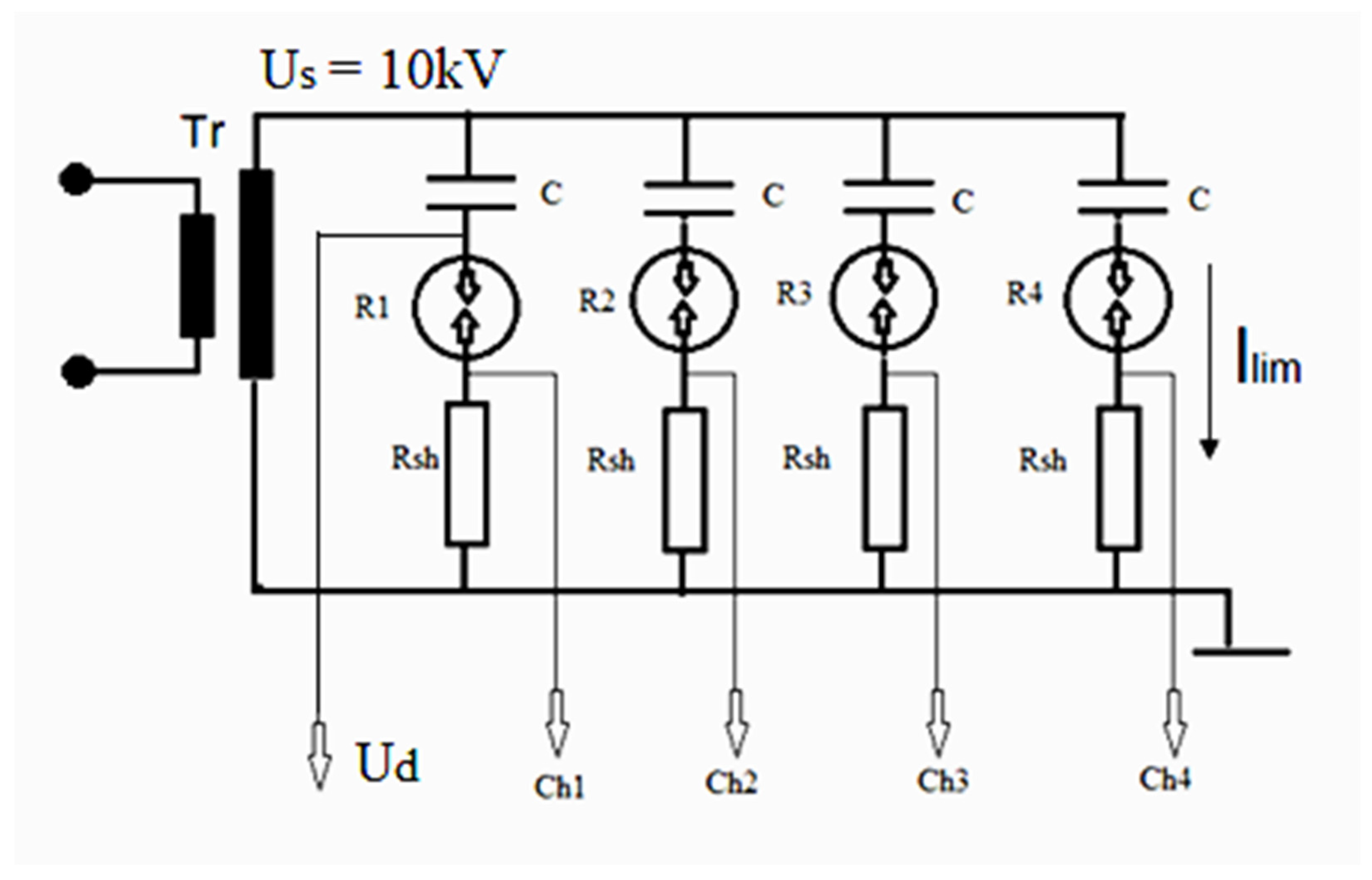
2.2. Capacitive Current Limitation Plasma Generator (CCL)

The main problem faced in the process of developing NTP systems on an industrial scale is the parallel evolution of electric discharges powered by a single main power supply. The parallel connection of several NTP reactors implies their simultaneous operation in the same conditions. This cannot be achieved by directly connecting the reactors in parallel due to the fact that, once an electric discharge is initiated, the voltage at the electrodes decreases and may not be high enough to ensure the initiation of the discharge in the adjacent reactor. This can be achieved by discharge current limitation through passive elements (R, L, and C) other than electrical resistors, which consume electrical power and reduce the efficiency of the multi-reactor system. However, the limitation of the current of discharge using inductive coils requires the same number of inductive coils of relatively high inductance values L, equal to the number of NTP reactors; as a result, they have a considerably large volume and are expensive.
Figure 3 presents the second schematic for the NTP reactors suitable to scale up the NTP reactors to a multi-reactor array. The second type of power supply uses a capacitive current limitation. The capacitive current limitation, as shown in Figure 3, could be an effective solution to upscale the NTP multi-reactor systems supplied by a regular HV AC transformer, where Tr is an AC transformer with secondary voltage Us = 10 kV/AC, Rsh = 63 Ω is the shunt for current measurement, and the capacitor C = 2 nF. In Figure 3, the NTP in the I-NTP type reactor is generated by an AC electrical discharge. The current is limited to an optimal value by a C capacitor.
In Figure 4, the current and voltage waveforms for the CCL plasma generator are presented. The current pulses occur when the voltage of the AC power supply overpasses the NTP reactor voltage breakdown threshold. The voltage of the AC transformer drops and the current pulse discharge stops. After increasing the voltage, another current pulse occurs. In our conditions, a train of pulses per voltage half-period is generated.

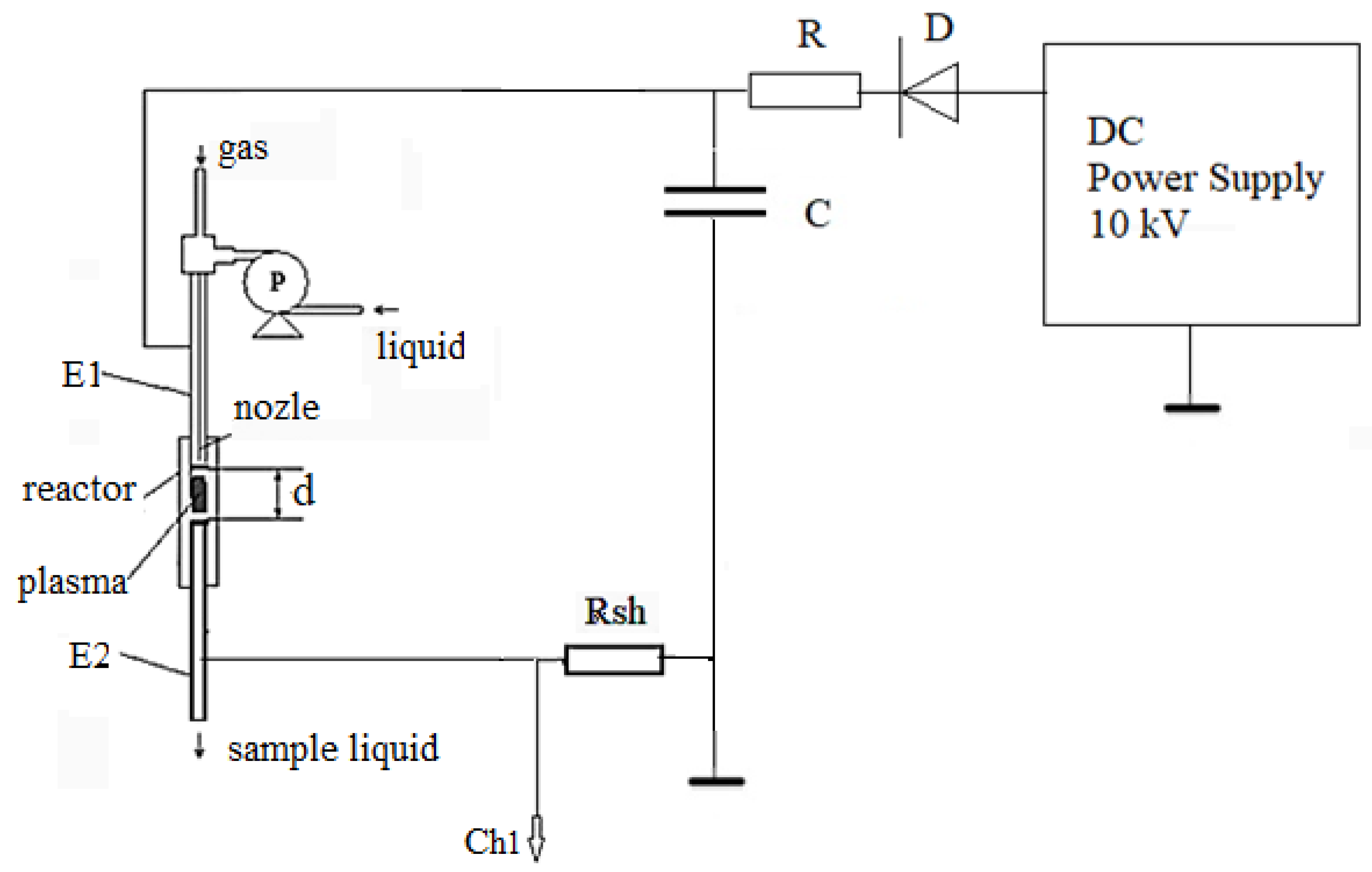
2.3. NTP Reactors Unit Powered by an R–C Pulse Generator (RCG)

A third possibility to scale up the NTP mini reactor systems consists of an R–C circuit pulse generator. In this case, the pulses are produced by the discharge of a charged capacitor from a direct current power supply (XP Glassman EJ30P20-HV power supply 0–30 KV, 600 W, positive polarity) through a resistor R. When the voltage on the capacitor reaches the breakdown voltage of the reactor air gap, the electrical discharge is initiated, and the capacitor quickly discharges directly on the NTP reactor circuit.
The experimental setup presented in Figure 5 uses 4 R–C circuits, where C = 2 nF, R = 2 MΩ, D is a suppressing diode, U = 10 kV DC, and Rsh = 3 Ω. Initially, the capacitor of each branch of the circuit charges from the DC power supply through the resistor R-diode D with the polarity shown in Figure 5. After the voltage of capacitor C reaches the voltage breakdown of the NTP reactor, the discharge is initiated and the capacitor discharges on the reactor producing NTP between its electrodes.
After the full discharge of the capacitor, the process starts over from the beginning. The voltage and current waveforms are presented in Figure 6.
The diode D prevents the discharge of another capacitor from another branch to the reactor; thus, the discharging of the capacitor on the reactor evolves independently of other circuits.

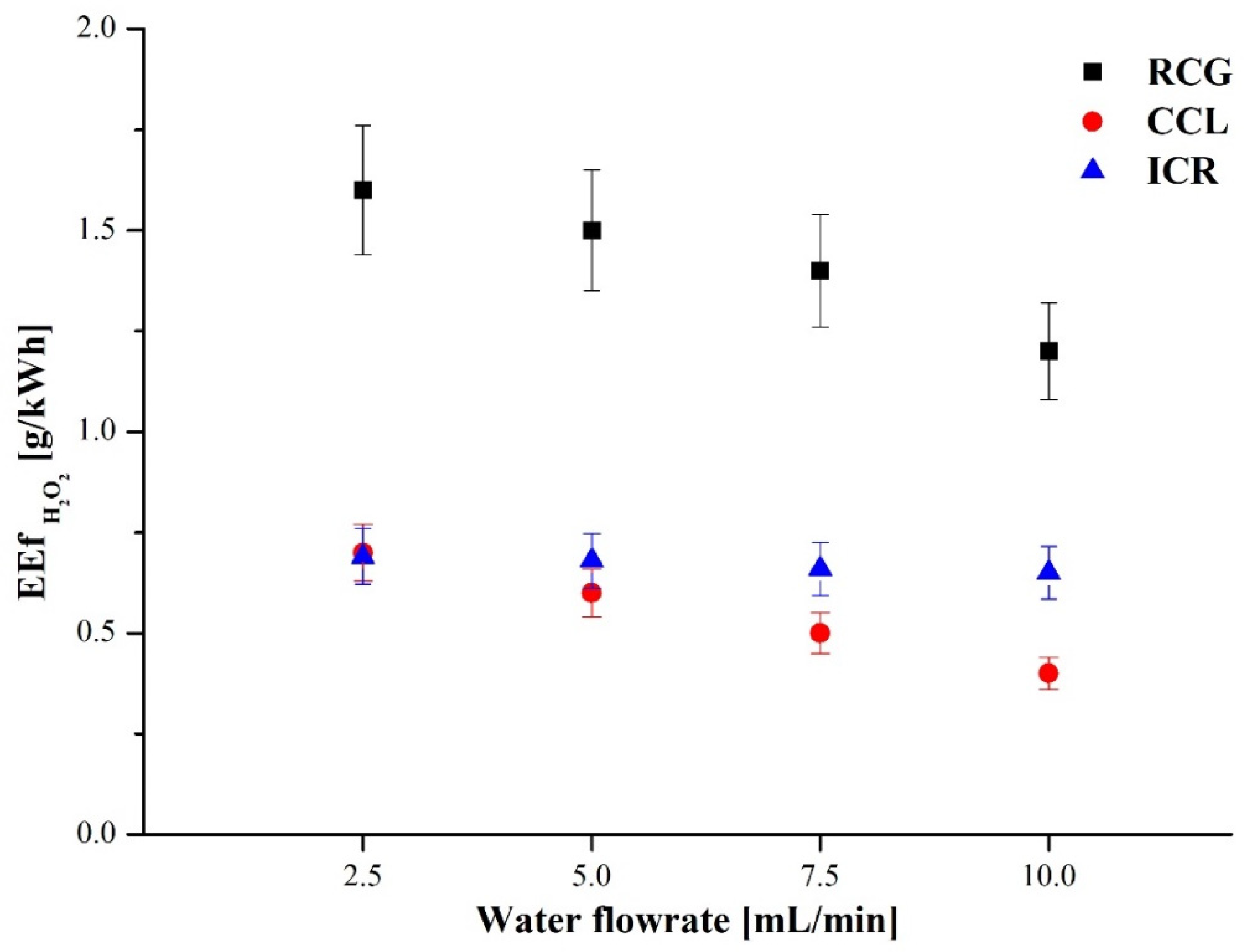
3. Results and Discussions

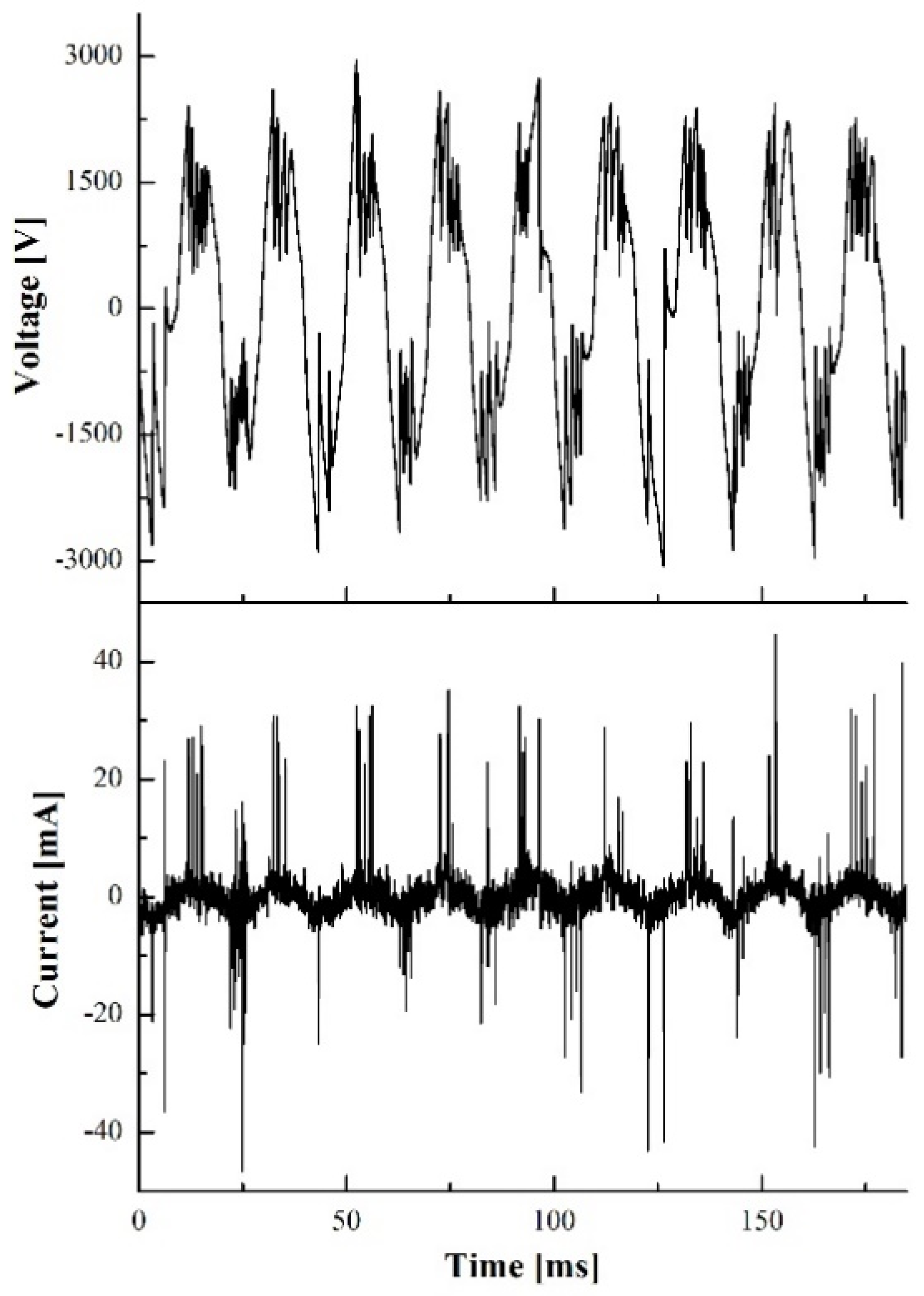
3.1. The Scale-Up of NTP Reactor Unit Powered by an Induction Coil-Driven Power Supply (ICR)

In order to increase the volume of the water treated or PAW, several reactors such as the one presented in Figure 1 are required to work in parallel, simultaneously. For example, Figure 7 presents the possibility of using 100 reactors powered by induction coils. In this first case, each reactor is supplied by its own HV pulse power supply. In this paper, the results obtained from operating only four reactors in parallel are presented.
The simplest method to use many NTP mini-reactors working simultaneously requires the use of a pulse power supply for each reactor (in our case, an automotive ignition coil driven by an IGBT transistor). This method is feasible but requires a number of ignition coils and drivers equal to the number of reactors, which is economically discouraging. Each reactor is powered by an ignition coil driven by a pulse generator as presented in Figure 1.
The power of the NTP discharge in the reactor was 3 W and the input power was 26 W, which had an electrical energy transfer efficiency of about 12–15%. The pulse duration was 1.5 ms.

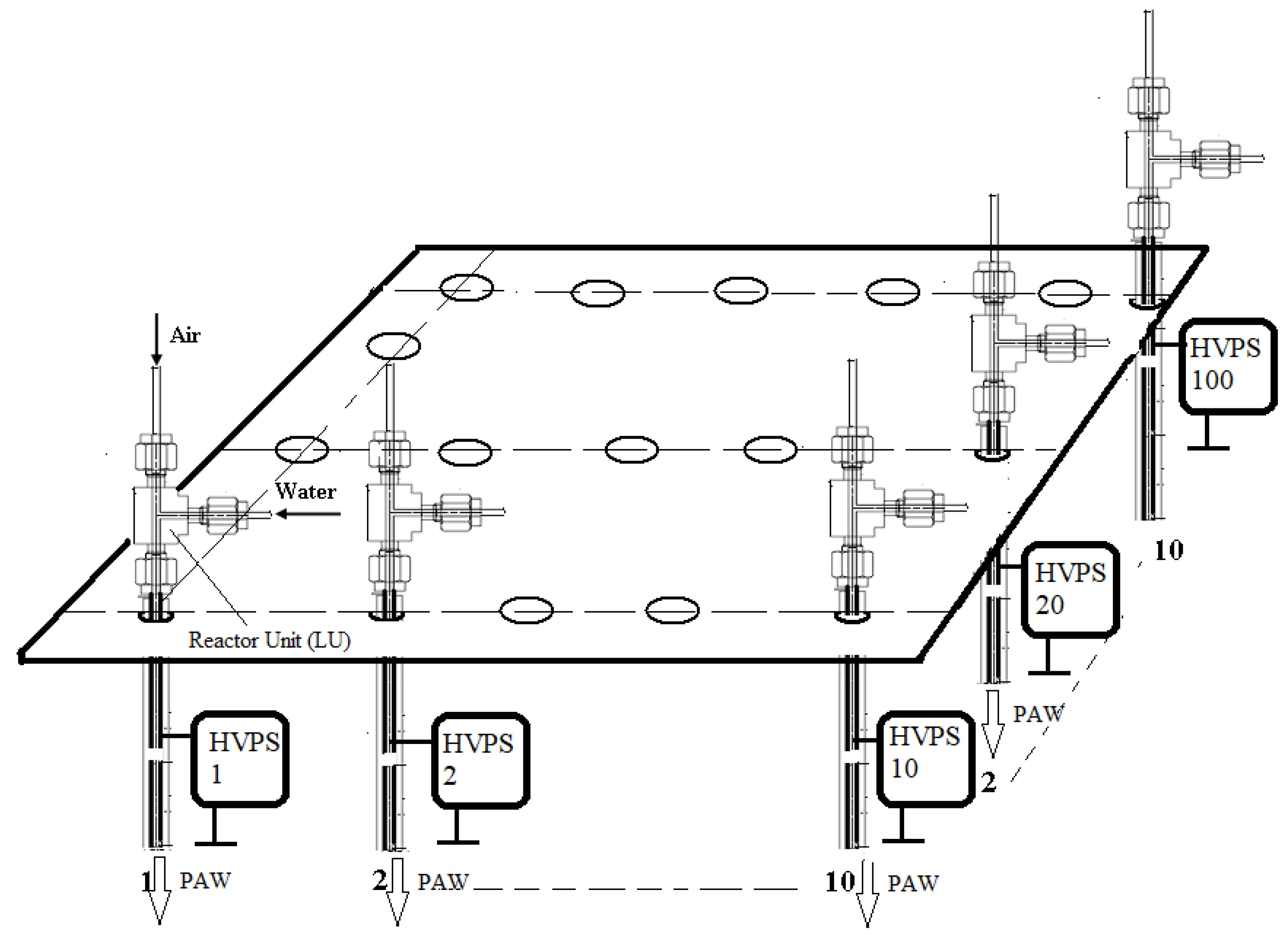
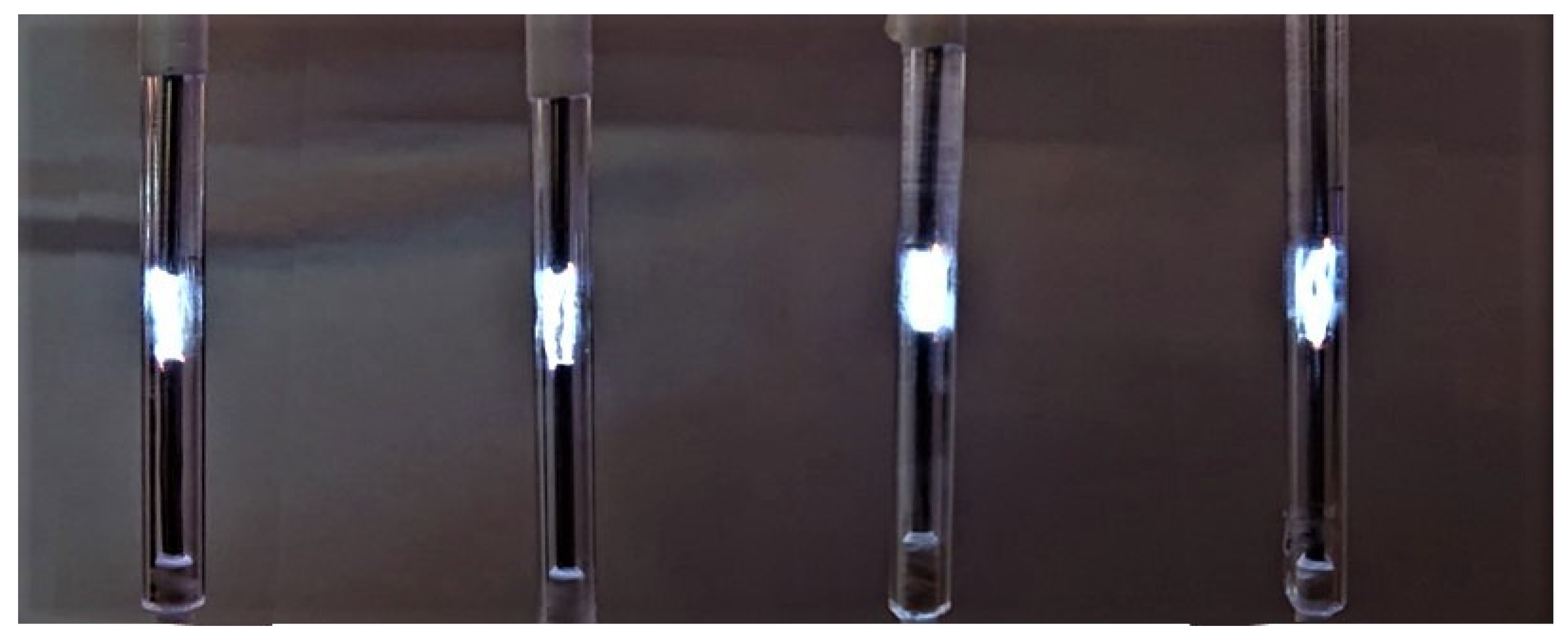
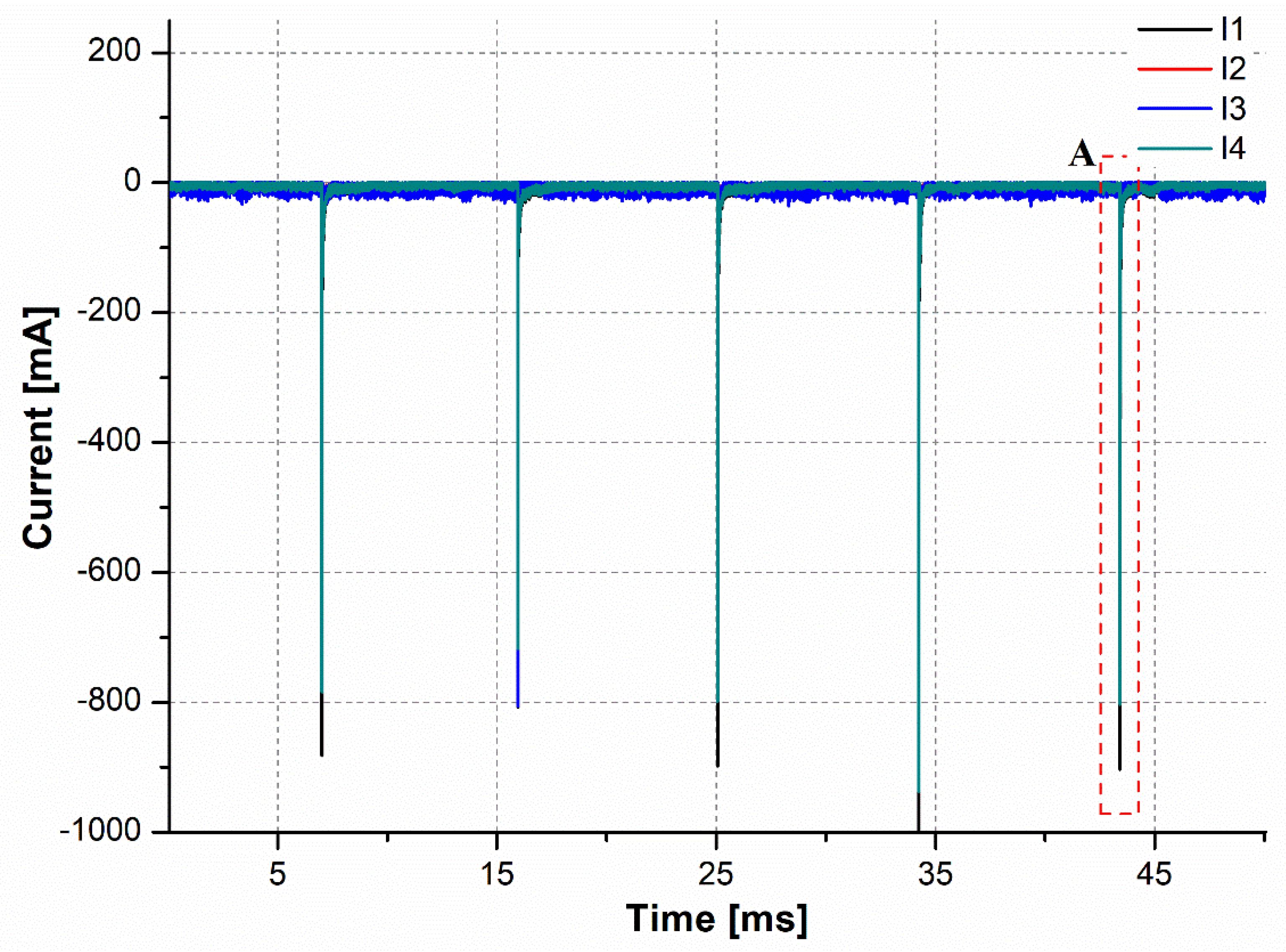
3.2. The Scale-Up of NTP Mini-Reactors for PAW Production by Capacitive Current Limitation. Capacitive Current Limitation Plasma Generator (CCL)

Since it is known that two electric discharges connected directly in parallel cannot work simultaneously, we can make the assumption that, if four electrical discharges in parallel can work at the same time, then any number of reactors, which comply with the required conditions, can be connected in parallel and supplied by the same AC transformer, as shown in Figure 8, where Tr is an AC transformer with secondary voltage Us =10 kV and an operating frequency f = 50 Hz, R1–R4 are point-to-point mini-reactors, Rsh = 63 Ω is the shunt for current measurement, and C = 2 nF.
In this configuration, the NTP current of the discharge is limited by a capacitor; therefore, the voltage on each “branch” of the reactor circuit is maintained at a value high enough to permit the voltage breakdown and the operation of other discharges connected in parallel.
The electrical schematic in Figure 8 shows that, when the first voltage breakdown occurs on one reactor, the discharge starts followed by a drop in the discharge voltage on the reactor electrodes. However, the voltage Us applied on other reactors is maintained at the same value due to the fact that the capacitor is connected in series with the reactor. This allows the ignition of the electrical discharges on other reactors and their independent evolution. Ilim is the current of the discharge limited by the impedance of the circuit. The value of the limited current can be expressed as
I lim = U s R 2 + ( 1 ω C ) 2 ,
where Us is the transformer voltage in transformer secondary, R is the resistance of the circuit including the secondary winding resistance (Rsh + resistance of secondary winding of transformer), C is the capacitor, and ω = 2πf (f is the frequency, 50 Hz).
The power of the reactor discharge is
P d = U d × I l i m ,
where Ud is the discharge voltage, which was measured directly using the Lecroy Wavesurfer 454 oscilloscope by the means of the Testec TT-HVP-2739 high-voltage probe, between the high voltage electrode E1 (see Figure 3) and the ground. Ilim is a notation for the current passing through the discharge and Rsh to the ground. For power measurement, Ilim was calculated considering the voltage drop on the shunt resistance Rsh. The power was numerically calculated considering the discharge voltage and current waveforms recorded by oscilloscope. The value of the energy measurement is evaluated on the basis of the average power calculated for 5–10 voltage periods, T.
The overall current that the transformer has to provide is
I s = 1 n I l i m ,
where Is is the current of the transformer in transformer secondary, and n is the number of reactors working in parallel.
The current of the NTP discharge is presented in Figure 9, where we can see that, although the voltage is alternating, the current of the discharge is pulsed (pulses are generated on each half cycle).
The current waveforms of all four reactors in phase demonstrating the quasi-simultaneous operation of all four discharges working in parallel are presented in Figure 10. A slight shift of a few μs between current pulses corresponding to each reactor can be observed.
Figure 11 presents a picture of four mini-reactors working in parallel. In this configuration, the average power of the discharge (on one reactor) is 9 W, which indicates an average energy efficiency of about 33–35%. A part of the energy is lost on the resistive–inductive circuit of the transformer (the losses in the transformer are caused by the resistance of the copper wires in the transformer: core losses, hysteresis losses, eddy current losses, and stray losses).
In addition to the evolution of currents I1, I2, I3, and I4 of the four reactors, Figure 11 demonstrates the simultaneous evolution of all four NTP discharges.

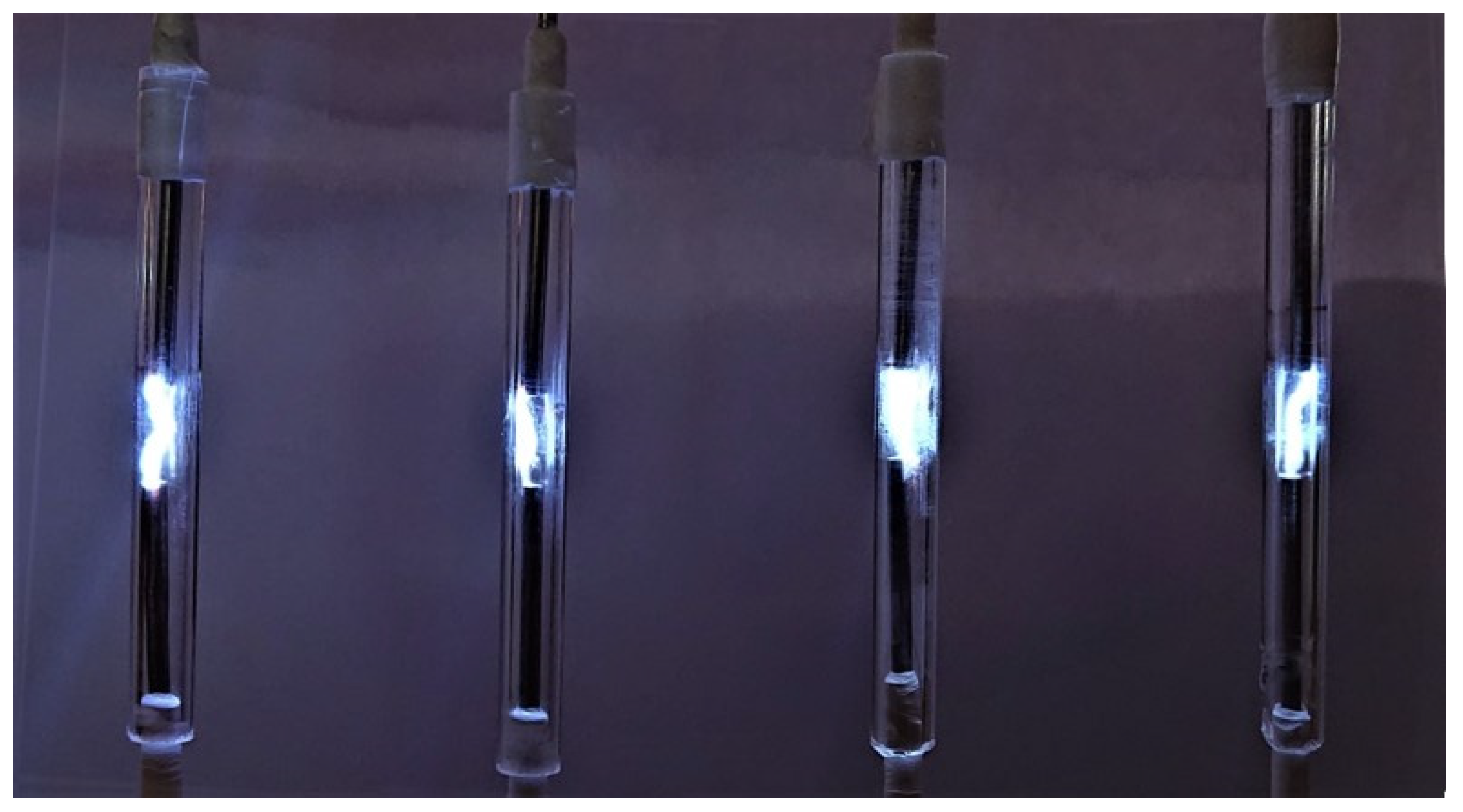
3.3. NTP Mini-Reactor Scale-Up Using R–C Pulse Generator (RCG)

As in the previous case, four reactors connected to work in parallel were considered to demonstrate the feasibility of the simultaneous operation of a large number of impulse discharges generated by the RC pulse-type power supply.
Figure 12 presents the schematic of the four reactors connected in parallel. The best results regarding the discharge stability were obtained for capacitors charging up to 65% of maximum voltage (on the linear charging slope of the capacitor voltage) corresponding to charging time constant T = RC. The breakdown voltage can be adjusted in this case by modifying the distance between the electrode air gap of the reactors.
The frequency of the pulses can be calculated using the following relation:
f = 1 R C .
The number of reactors of the system can be found with the following relation:
n = Q t Q r ,
where Qt is the total flow rate of the solution to be treated, and Qr is the flow rate of each reactor.
The energy required by the chemical process, Ec, for each reactor is also known. The energy of each capacitor is
E c = C U 2 2 .
The maximum value of the current Imax is
I m a x = 1 n U R i = n U R ,
where n is the number of NTP reactors connected in parallel.
The values of C and R can be found as follows:
C = I m a x n U f ,
R = U 2 2 f E c .
Figure 13 presents the current waveforms for all four reactors. The number of pulses per second can also establish the frequency of the power supply as the total energy required by the system divided by Ec.
According to the general requirements of the system in terms of energy and total flow rate to be treated, the values of R and C can be calculated.
In order to demonstrate the feasibility of scaling up the system, four reactors were connected in parallel to a direct current power supply through an RC network as in Figure 12. The current waveforms for each reactor were measured.
Figure 14 shows that all four pulses (the current for the four reactors I1, I2, I3, and I4) of the discharges were in phase, indicating that all the discharges were evolving at the same time.
Similar to the previous case, Figure 15 demonstrates the simultaneous evolution of the four NTP generating discharges.
In this case, the current of all four reactors again evolved simultaneously, demonstrating the feasibility of scaling up the NTP reactor system to industrial scale.
The frequency of the pulses was 600 Hz, the input power was about 8 W, and the energy transfer efficiency in this case was about 38–40%. The energy efficiency transfer can be optimized, depending on the electrical parameters of the electrical schematic. The pulse duration in this case was 0.5 ms. The frequency and the power of the discharge could be adjusted by modifying the value of the capacitor and/or the resistance of the RC circuit. This leads to the possibility to control the PAW chemical composition without modifying the gas or water flow rates.
In order to compare the efficiency of the three types of power supplies for NTP mini-reactors (RCG, CCL, and ICR), deionized (DI) water was treated in all three configurations with Ar as the carrier gas, while the concentration of hydrogen peroxide (Figure 16) and the H2O2 energy efficiency (EEfH2O2; Figure 17) were calculated. EEfH2O2 represents the quantity of the H2O2 generated in water (in grams) for 1 kWh of energy used. In our case, EEfH2O2 was calculated considering the input power of the NTP reactors.
As shown in Figure 16 and Figure 17, the hydrogen peroxide production in the ICR reactor was higher than that in the capacitive current limited CCL reactor and RCG; on the contrary, the energy efficiency production of hydrogen peroxide (EEfH2O2) was almost two times higher in the RCG reactor than in the other two NTP reactors (ICR and CCL).
Table 1 presents the pulse energy and electrical efficiency for the proposed power supplies. The electrical efficiency represents the ratio between the energy delivered to the discharge and the input energy of the power supply. For the ICR case, the total electrical power was the highest in the range of 26 W, but it had the lowest electrical efficiency of only 12% to 15%. The highest electrical efficiency was found to be in the case of RCG power supply.
The values presented in Table 1 can vary, being subject to the chemical/physical conditions of use of the reactors.
In this paper, the energy efficiency for hydrogen peroxide production was found to be around 0.7–0.8 g/kWh for the ICG reactor. S previous study addressing a similar configuration of NTP reactors supplied by an induction coil pulse power supply [25] indicated an efficiency for H2O2 production of 0.2–0.3 g/kWh in the case of a mini-reactor with nonsymmetrical electrodes. In the case of T-shaped reactors [26], an energy efficiency of 0.6–0.7 g/kWh was achieved. The energy efficiency for H2O2 production in all cases was calculated related to the inlet energy of the electrical power supply, which, in the case of the ignition coil, was about 26 W, not related to the energy of the electrical discharge, as indicated in the papers mentioned above.
The measured discharge power reported in this paper of around 3–4 W is similar to the power reported by other papers treating a similar geometry of NTP reactors supplied by an ignition coil [27].

4. Conclusions

This paper presented three different types of power supplies that allow operating with multiple NTP reactors connected in parallel. The efficiency of the proposed power supplies was evaluated on the basis of the hydrogen peroxide production energy efficiency in deionized water.
The capacitive pulsed HV power supplies allow the parallel operation of a large number of electric discharges equivalent to a number of NTP reactors working quasi-simultaneously, demonstrating the feasibility of upscaling the reactor systems to an industrial level. It is possible to obtain HV pulses from an AC power supply (usually an AC transformer) using the capacitive limitation of the discharge current, as well as from a DC power supply using an R–C circuit pulse generator.
The number of the NTP reactors working in parallel depends (is limited to) only on the electrical power delivered by the AC transformer or DC power supply.
The highest concentration of H2O2 was obtained in the case of ICR, but the highest energy efficiency in hydrogen peroxide production was found in the case of RCG. This is due to the fact that the pulse duration is shorter; hence, thermal losses are lower, and a higher amount of energy is used for hydrogen peroxide production.
The choice of one of the proposed solutions should take into account both the parameters imposed for the activated water and the economic analysis of the entire reactor system. In the case of applications that require lower concentrations of H2O2 (agricultural applications), the RCG supply scheme is suitable as it ensures a high efficiency in the generation of H2O2. If a high concentration of H2O2 is required (e.g., applications for wastewater depollution), the ICR power supply is preferable.
From an economic point of view, when it is necessary to use a very large number of reactors, the CCL-type source is the most suitable, having the lowest investment (implementation) costs. However, a technical and economic analysis is required in this case.

Author Contributions

Conceptualization, D.A. and R.B.; methodology, D.A. and R.B.; validation, D.-E.C., D.A., and O.B.; investigation, D.-E.C. and R.B.; resources, D.A., R.B., and D.-E.C.; data curation, D.A. and O.B.; writing—original draft preparation, R.B. and D.A.; writing—review and editing, D.A., D.-E.C., O.B., and R.B; visualization, O.B.; supervision, R.B.; project administration, R.B.; funding acquisition, D.A. All authors have read and agreed to the published version of the manuscript.

Funding

This work was supported by Romanian National Authority for Scientific Research and Innovation, CCCDI–UEFISCDI, grant ERANET-MANUNET-III-PlasmaPack, no. 214/2020 and grant PN-III-P2-2.1-PED-2019-0556, no. 361PED/2020—PhytoPAW, and by “Gheorghe Asachi” Technical University of Iasi.

Institutional Review Board Statement

Not applicable.

Informed Consent Statement

Not applicable.

Data Availability Statement

Not applicable.

Conflicts of Interest

The authors declare no conflict of interest.

References

  1. Judée, F.; Simon, S.; Bailly, C.; Dufour, T. Plasma-Activation of Tap Water Using DBD for Agronomy Applications: Identification and Quantification of Long Lifetime Chemical Species and Production/Consumption Mechanisms. Water Res. 2018, 133, 47–59. [Google Scholar] [CrossRef] [PubMed] [Green Version]
  2. Stoleru, V.; Burlica, R.; Mihalache, G.; Dirlau, D.; Padureanu, S.; Teliban, G.-C.; Astanei, D.; Cojocaru, A.; Beniuga, O.; Patras, A. Plant growth promotion effect of plasma activated water on Lactuca sativa L. cultivated in two different volumes of substrate. Sci. Rep. 2020, 10, 20920. [Google Scholar] [CrossRef] [PubMed]
  3. Jiang, J.; He, X.; Li, L.; Li, J.; Shao, H.; Xu, Q.; Ye, R.; Dong, Y. Effect of Cold Plasma Treatment on Seed Germination and Growth of Wheat. Plasma Sci. Technol. 2014, 16, 54–58. [Google Scholar] [CrossRef] [Green Version]
  4. Bruggeman, P.J.; Kushner, M.J.; Locke, B.R.; Gardeniers, J.G.E.; Graham, W.G.; Graves, D.B.; Hofman-Caris, R.C.H.M.; Maric, D.; Reid, J.P.; Ceriani, E.; et al. Plasma-liquid interactions: A review and roadmap. Plasma Sources Sci. Technol. 2016, 25, 053002. [Google Scholar] [CrossRef] [Green Version]
  5. Mrotzek, J.; Viöl, W. Spectroscopic Characterization of an Atmospheric Pressure Plasma Jet Used for Cold Plasma Spraying. Appl. Sci. 2022, 12, 6814. [Google Scholar] [CrossRef]
  6. Kirkpatrick, M.J.; Odic, E.; Leininger, J.-P.; Blanchard, G.; Rousseau, S.; Glipa, X. Plasma assisted heterogeneous catalytic oxidation of carbon monoxide and unburned hydrocarbons: Laboratory-scale investigations. Appl. Catal. B Environ. 2011, 106, 160–166. [Google Scholar] [CrossRef]
  7. Dai, F.; Fan, X.; Stratton, G.R.; Bellona, C.L.; Holsen, T.M.; Crimmins, B.S.; Xia, X.; Thagard, S.M. Experimental and density functional theoretical study of the effects of Fenton’s reaction on the degradation of Bisphenol A in a high voltage plasma reactor. J. Hazard. Mater. 2016, 308, 419–429. [Google Scholar] [CrossRef] [PubMed]
  8. Young, T.; Geng, M.; Lin, L.; Thagard, S.M. Oxidative Degradation of Bisphenol A: A Comparison Between Fenton Reagent, UV, UV/H2O2 and Ultrasound. J. Adv. Oxid. Technol. 2013, 16, 89–101. [Google Scholar] [CrossRef]
  9. Lukes, P.; Dolezalova, E.; Sisrova, I.; Clupek, M. Aqueous-Phase Chemistry and Bactericidal Effects from an Air Discharge Plasma in Contact with Water: Evidence for the Formation of Peroxynitrite through a Pseudo-Second-Order Post-Discharge Reaction of H2O2 and HNO2. Plasma Sources Sci. Technol. 2014, 23, 015019. [Google Scholar] [CrossRef]
  10. Xu, H.; Zhu, Y.; Du, M.; Wang, Y.; Ju, S.; Ma, R.; Jiao, Z. Subcellular Mechanism of Microbial Inactivation during Water Disinfection by Cold Atmospheric-Pressure Plasma. Water Res. 2021, 188, 116513. [Google Scholar] [CrossRef] [PubMed]
  11. Titov, E.Y.; Bodrikov, I.V.; Serov, A.I.; Kurskii, Y.A.; Titov, D.Y.; Bodrikova, E.R. Liquid-Phase Non-Thermal Plasma Discharge for Fuel Oil Processing. Energies 2022, 15, 3400. [Google Scholar] [CrossRef]
  12. Bai, H.; Huang, B.; Liy, Y.; Zhang, C.; Shao, T. Reaction mechanism in non-thermal plasma enabled methane conversion: Correlation between optical emission spectroscopy and gaseous products. J. Phys. D Appl. Phys. 2021, 54, 424002. [Google Scholar] [CrossRef]
  13. Franclemont, J.; Fan, X.; Thagard, S.M. Physicochemical mechanisms of plasma-liquid interactions within plasma channels in liquid. J. Phys. D Appl. Phys. 2015, 48, 424004. [Google Scholar] [CrossRef]
  14. Burlica, R.; Shih, K.Y.; Locke, B.R. Formation of H2 and H2O2 in a Water-Spray Gliding Arc Nonthermal Plasma Reactor. Ind. Eng. Chem. Res. 2010, 49, 6342–6349. [Google Scholar] [CrossRef]
  15. Burlica, R.; Hnatiuc, B.; Hnatiuc, E.; Ursache, M. Effect of electrical current on H2/ H2O2 generation in non-thermal plasma gliding arc reactors. Environ. Eng. Manag. J. 2011, 10, 579–583. [Google Scholar] [CrossRef]
  16. Burlica, R.; Finney, W.C.; Locke, B.R. Effects of the Voltage and Current Waveforms and Discharge Power on Hydrogen Peroxide Formation in Water-Spray Gliding Arc Reactor. IEEE Trans. Ind. Appl. 2013, 49, 1098–1103. [Google Scholar] [CrossRef]
  17. Locke, B.R.; Shih, K.Y. Review of the methods to form hydrogen peroxide in electrical discharge plasma with liquid water. Plasma Sources Sci. Technol. 2011, 20, 034006. [Google Scholar] [CrossRef]
  18. Burlica, R.; Dirlau, I.D.; Astanei, D. Non-thermal plasma mini-reactors for water treatment. Environ. Eng. Manag. J. 2019, 18, 1799–1807. [Google Scholar] [CrossRef]
  19. Zambon, Y.; Contaldo, N.; Laurita, R.; Várallyay, E.; Canel, A.; Gherardi, M.; Colombo, V.; Bertaccini, A. Plasma activated water triggers plant defence responses. Sci. Rep. 2020, 10, 19211. [Google Scholar] [CrossRef] [PubMed]
  20. Adhikari, B.; Adhikari, M.; Ghimire, B.; Park, G.; Choi, E.H. Cold Atmospheric Plasma-Activated Water Irrigation Induces Defense Hormone and Gene expression in Tomato seedlings. Sci. Rep. 2019, 9, 16080. [Google Scholar] [CrossRef]
  21. Xiang, Q.; Fan, L.; Li, Y.; Dong, S.; Li, K.; Bai, Y. A review on recent advances in plasma-activated water for food safety: Current applications and future trends. Crit. Rev. Food Sci. Nutr. 2020, 2250–2268. [Google Scholar] [CrossRef] [PubMed]
  22. Kirkpatrick, M.; Locke, B.R. Hydrogen, oxygen and hydrogen peroxide formation in aqueous phase pulsed corona electrical discharge. Ind. Eng. Chem. Res. 2005, 44, 4243–4248. [Google Scholar] [CrossRef]
  23. Burlica, R.; Locke, B.R. Pulsed Plasma Gliding-Arc Discharges with Water Spray. IEEE Trans. Ind. Appl. 2008, 44, 482–489. [Google Scholar] [CrossRef]
  24. Eisenberg, G.M. Colorimetric determination of hydrogen peroxide. Ind. Eng. Chem. Anal. Ed. 1943, 15, 327–328. [Google Scholar] [CrossRef]
  25. Burlica, R.; Wendell, R.; Locke, B.R. Effect of Non-Thermal Plasma Electrical Parameters on Hydrogen Peroxide Generation in Pulse Gliding Arc Mini-Reactors. In Proceedings of the 32nd International Conference on Phenomena in Ionized Gases (ICPIG), Iași, Romania, 26–31 July 2015. [Google Scholar]
  26. Cretu, D.E.; Astanei, D.; Burlica, R.; Beniuga, O.; Tesoi, D. The Influence of NTP Reactor Geometry on H2O2Generation in Water. In Proceedings of the 11th International Conference and Exposition on Electrical And Power Engineering (EPE 2020), Iaşi, Romania, 22–23 October 2020; Institute of Electrical and Electronics Engineers Inc.: Piscataway, NJ, USA, 2020; pp. 632–635. [Google Scholar]
  27. Hsieh, K.C.; Wang, H.; Locke, B.R. Analysis of Electrical Discharge Plasma in a Gas-Liquid Flow Reactor Using Optical Emission Spectroscopy and the Formation of Hydrogen Peroxide. Plasma Process. Polym. 2016, 13, 908–917. [Google Scholar] [CrossRef]
Figure 1. The schematic of NTP reactor powered by a pulse induction coil power supply (ICR).
Applsci 12 10403 g001
Figure 2. The current and the voltage waveforms for induction coil power supply (ICR).
Applsci 12 10403 g002
Figure 3. The schematic of capacitive current limitation plasma generator (CCL).
Applsci 12 10403 g003
Figure 4. The current and the voltage wave forms for CCL power supply.
Applsci 12 10403 g004
Figure 5. The schematic of the NTP reactor with R–C pulse generator (RCG).
Applsci 12 10403 g005
Figure 6. The current and the voltage waveforms for CCL power supply.
Applsci 12 10403 g006
Figure 7. The schematic of multi-NTP reactor array powered by induction coil driven power supplies (ICR).
Applsci 12 10403 g007
Figure 8. NTP mini-reactor scale-up by capacitive current limitation.
Applsci 12 10403 g008
Figure 9. The current waveforms of the four NTP multi-reactors (R1–R4)—CCL type working in parallel.
Applsci 12 10403 g009
Figure 10. CCL-type NTP multi-reactor current waveforms—zoomed-in view on one set of current pulses.
Applsci 12 10403 g010
Figure 11. Four discharges working in parallel for CCL type of NTP mini-reactor.
Applsci 12 10403 g011
Figure 12. NTP scale-up using R–C pulse generator (RCG).
Applsci 12 10403 g012
Figure 13. Current waveforms of the four RCG reactors working in parallel—the current for the four reactors (I1–I4).
Applsci 12 10403 g013
Figure 14. Current waveforms of R–C pulse generator (RCG)—zoomed-in view of one set of four pulses (I1, I2, I3, I4).
Applsci 12 10403 g014
Figure 15. The four RCG reactors working in parallel.
Applsci 12 10403 g015
Figure 16. H2O2 production in ICR, CCL, and RCG reactors with Ar.
Applsci 12 10403 g016
Figure 17. H2O2 production efficiency in ICR, CCL, and RCG reactors.
Applsci 12 10403 g017
Table 1. Pulse energy and electrical efficiency for the proposed power supplies.
Power SupplyPulse Energy (J/pulse)Total Power (W)Electrical Efficiency (%)
ICR15 × 10−3 ± 1.52612–15
CCL6 × 10−3 ± 1.5933–35
RCG4 × 10−3 ± 1.5838–40
Publisher’s Note: MDPI stays neutral with regard to jurisdictional claims in published maps and institutional affiliations.

