Article

Study of In-Plane Mechanical Properties of Novel Ellipse-Based Chiral Honeycomb Structure

1
School of Civil Engineering and Architecture, Suqian University, Suqian 223800, China
2
School of Civil Engineering, Shenyang Jianzhu University, Shenyang 110168, China
*
Author to whom correspondence should be addressed.
Appl. Sci. 2022, 12(20), 10437; https://doi.org/10.3390/app122010437
Submission received: 13 September 2022 / Revised: 10 October 2022 / Accepted: 13 October 2022 / Published: 16 October 2022
(This article belongs to the Special Issue Advances in Metamaterials for Sound and Vibration Control)

Abstract

:
In this paper, we propose an elliptical anti-tetrachiral honeycombs structure (E-antitet) with in-plane negative Poisson’s ratio (NPR) and orthogonal anisotropy. The analytical and numerical solutions of the in-plane Poisson’s ratio and Young’s modulus are given by theoretical derivations and finite element method (FEM) numerical simulations and are verified experimentally by a 3D printed sample. Finally, we analyzed the influences of different parameters on the in-plane Poisson’s ratio and Young’s modulus of E-antitet. The results show that the proposed E-antitet can achieve a smaller Poisson’s ratio and larger Young’s modulus in the desired direction compared with the anti-tetrachiral honeycombs structure (antitet), and moreover, the E-antitet has a more flexible means of regulation than the antitet. The analytical results of this paper provide meaningful guidance for the design of chiral honeycomb structures.

1. Introduction

Negative Poisson’s ratio (NPR) honeycomb structures refer to a class of man-made structural functional materials whose cross-sections become more expanded when stretched. Although scholars have previously discovered some natural materials with NPR effects, such as some metals [1], cancellous bones [2], cat skin [3] and parts of cow skin [4], the study on NPR materials started in the 1980s: Gibson et al. [5] systematically investigated the in-plane mechanical properties of hexagonal honeycomb structures with different parameters and found that re-entrant hexagonal honeycomb structures could produce the NPR effect; this result quickly attracted the attention of scholars, and different types of NPR structures were proposed, respectively. Almgren [6] designed a structure using rods, hinges and springs in two and three dimensions and found its Poisson’s ratio to be −1; Lakes [7] obtained a foam material with a Poisson’s ratio of −0.7 under compression in a heated mold using polyester foam as raw material and predicted the advantages and applications of NPR materials; Evans et al. [8] designed NPR materials at the molecular level and named them Auxetics. As the research progresses, many unique and novel properties of NPR materials are gradually discovered, such as the varying porosity of NPR materials with strain [9,10,11] and isotropic curvature when subjected to out-plane bending [12,13]. In addition, many mechanical properties of NPR materials are enhanced compared to those of ordinary materials, such as indentation resistance [14,15,16,17,18], shear modulus/fracture toughness [19,20,21,22,23] and energy absorption [24,25,26,27]. Moreover, the properties of NPR materials are scale-independent and can be both the overall behavior of the material and originate from its internal structure, which means that they are both macroscopic material properties and microscopic internal structure properties [28].
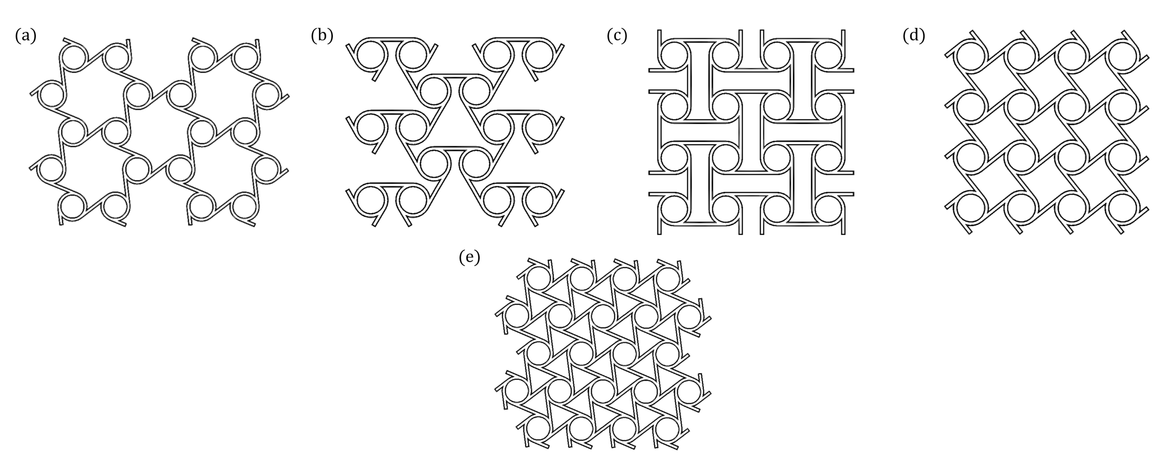
Among many of the NPR honeycomb structures, chiral honeycomb structures have been widely studied due to their superior NPR effects and excellent designability. A typical chiral honeycomb structure usually consists of two parts, which are the central node and the ligaments connected tangentially to the central node. Depending on the position and number of ligaments, chiral honeycomb structures can be classified into tri-trichiral honeycomb structure (tri)/anti-trichiral honeycomb structure (antitri), tetrachiral honeycomb structure (tet)/anti-tetrachiral honeycomb structure (antitet) and hexachiral honeycomb structure (hex), as shown in Figure 1. The NPR effect of chiral honeycomb structures originates from their unique deformation pattern, where the central node rotates when stressed in one direction and the ligaments connected to the central node bend, which leads to a kink in the whole structure and exhibits NPR effects. This unique deformation mode makes the chiral honeycomb structures have stable NPR over a wide range of strains. The study of chiral honeycomb structures by scholars began in the late 1980s: Wojciechowski [29] first proposed that the NPR effect could be generated using rotating node topology; Lakes [30] proposed that chiral honeycomb structures can produce NPR effects; Prall et al. [31] proposed hex and determined its parameters, basic theory and calculation methods to prove that the Poisson’s ratio of hex is -1; Alderson et al. [32] investigated the in-plane mechanical properties of tri, antitri, tet, antitet and hex through theoretical derivations, finite element method (FEM) simulations and experiments and discussed the deformation mechanism of chiral honeycomb structures; Lorato et al. [33] investigated the out-plane mechanical properties of tri, antitri, tet, antitet and hex using theoretical derivations, FEM simulations and experiments; Mousanezhad et al. [34] conducted a theoretical derivations of Young’s modulus for several chiral honeycomb structures and polygonal lattice sandwich honeycomb structures based on the energy method and verified the correctness of the theoretical derivations by combining FEM simulations; Spadoni et al. [35] and Scarpa et al. [36] studied the elastic buckling of hex using theoretical derivations and FEM simulations, on the basis of which Miller et al. [37] proposed a complete hysteretic elastic buckling model and mechanical characteristics of hex. In addition to the studies on the regular two-dimensional chiral honeycomb structures, many scholars have also conducted in-depth studies on the special two-dimensional chiral honeycomb structures [38,39] and three-dimensional chiral honeycomb structures [40,41,42,43,44,45].
NPR honeycomb structures have been widely used in various fields due to their performance advantages [46,47,48,49], but the disadvantages of weak load-bearing capacity [50] of two-dimensional NPR honeycomb structures limit the relevant engineering applications. Some scholars have already made corresponding improvements based on the disadvantages of the low Young’s modulus of the NPR honeycomb [51,52,53]. Recently, Mukhopadhyay et al. [54] developed microstructures that can exhibit multidirectional auxeticity covering the in-plane and out-of-plane directions including mixed-mode modulation. The proposed 3D microstructure could be extended to different other beam profiles with spatially varying geometrical and material parameters, making it an ideal candidate for the creation of innovative programmable structural systems. To the best of our knowledge, no study has been conducted in the open literature to improve the central node to enhance the in-plane Young’s modulus of chiral honeycomb structures, so it is necessary to study new chiral honeycomb structure. However, this area of research is still far from enough due to the large porosity of NPR structures. In addition, conventional NPR materials are often designed as isotropic structures, which limits the adjustment range of negative Poisson’s ratio to some extent. In this paper, we design an elliptical anti-tetrachiral honeycombs structure (E-antitet) with orthogonal anisotropic elastic constants, which can improve its material strength in at least one direction and has a wide range of Poisson’s ratio adjustment. This gives our proposed E-antitet a more flexible means of regulation.
The paper is organized as follows: Section 1 introduces the research advances, specific applications and current disadvantages of NPR honeycomb structures, especially chiral honeycomb structures; Section 2 shows the theoretical derivations, FEM simulations and experimental validation of the in-plane mechanical properties of E-antitet; Section 3 analyzes the effects of parameters on the in-plane mechanical properties of E-antitet; Section 4 summarizes the full work.

2. Theoretical Derivations, FEM Simulations and Experimental Verification of In-Plane Mechanical Properties of E-Antitet

2.1. Unit Cell and Parameters of E-Antitet

Figure 2a shows the schematic of the E-antitet cell and its parameters, where l x and l y represent the lengths of the ligament in the x - and y -directions, respectively; l e x and l e y represent the effective lengths of the ligaments in the x - and y -directions, respectively; a and b represent the lengths of the long and short axis of the elliptical node ring, respectively; t is the width of the ligaments and the elliptical node ring; and the depth of the cell in the z -direction is d . To convenience the study, we defined nine dimensionless parameters, which are δ = a / b , α a x = l x / a ,   α a y = l y / a , α b x = l x / b ,   α b y = l y / a , β a = t / a , β b = t / b , γ a = d / a and γ b = d / b . There are five independent parameters, which are δ , α a x = 1 / δ α b x , α a y = 1 / δ α b y , β a = 1 / δ β b and γ a = 1 / δ γ b . When a = b , E-antitet degenerates to antitet.

2.2. Theoretical Derivations

Similar to the references [31,32,55], the elliptical node ring in the E-antitet is likewise assumed to be a completely rigid unit of rotation, with only minor deformation occurring within the ligament. Using the classical beam theory related to the ligament deformation mechanism, Poisson’s ratio can be derived for all chiral honeycomb structures.
According to Figure 2b and simple geometric relations, it can be found that the E-antitet cell produces a turning angle θ when the elliptical nodal ring is compressed in the x - and y -directions, and the length of the ligament being rotated into the nodal ring is the elongation Δ l x . Thus, the strain along the x - and y -directions can be expressed as:
ε x = Δ l x l x = 2 ( a t / 2 ) θ l x
ε y = Δ l y l y = 2 ( b t / 2 ) θ l y
While the ligament bending caused by node rotation is considered as the dominant deformation, the Poisson’s ratios v x y and v y x can be calculated from the definition [55]:
v x y = ε y ε x = ( b t / 2 ) l x ( a t / 2 ) l y
v y x = ε x ε y = ( a t / 2 ) l y ( b t / 2 ) l x
where:
a t / 2 b t / 2 > 1
which means:
l y l x > ( a t / 2 ) l y ( b t / 2 ) l x
while the Poisson’s ratios of antitet are [55]:
v x y = ε y ε x = l x l y
v y x = ε x ε y = l y l x
Chiral honeycomb structures usually use the energy approach to obtain the Young’s modulus of their structures. According to the principle of energy conservation, the strain energy caused by the strain ε i in i -direction is equal to the total of the energy stored in each bending ligament in the unit volume of the cell ( W r i b i ), which means:
U = 1 2 E i ε i 2 = 8 V W r i b i = 4 V W r i b x + 4 V W r i b y
where E i and V ( V = 4 l x l y d ) are the Young’s modulus and volume respectively representing the i -direction occupied by the cell, while W r i b i is the energy stored in the ligament in the i -direction. It is worth noting that since the ligament and the elliptical node ring have overlap, and the ligament in the overlap part cannot store energy, we use the length of the effective ligament to calculate it. By establishing a simple coordinate system in Figure 2a, we can find the intersection point of the inner part of any ligament with the outer part of the elliptical node ring and calculate its coordinate values as y 1 = a t and x 1 = b a 2 a t t 2   according to the elliptic equation. Then we can obtain the effective ligament lengths ( l e x and l e y ) calculated as:
l e x = l x 2 b a 2 a t t 2
l e y = l y 2 a b 2 b t t 2
According to the classical beam theory, two equal and opposite moments M acting at the ends of the ligament can cause the ligament to turn at the end points, which means the same as the turning angle θ generated by the node ring. Therefore, the strain energy of the beam can be expressed as:
W r i b i = 2 0 θ M d θ
The angle at which the elliptical node ring turns through is obtained from the deflection equation of the beam as:
θ = M l e i / 2 E s I
where E s and I ( I = d t 3 / 12 ) are the Young’s modulus and the moment of inertia of the ligament respectively representing the base material. Substituting Equation (12) into Equation (11), a new expression for W r i b i can be obtained as:
W r i b i = E s d t 3 θ 2 6 l e i
When small strains ε x and ε y are applied to the cell, two new energy expressions are obtained by substituting Equations (1), (2) and (14) into Equation (9):
U = 1 2 E x ε x 2 = E s d t 3 ε x 2 l x 2 24 l e x ( a t / 2 ) 2 l x l y d + E s d t 3 ε x 2 l x 2 24 l e y ( a t / 2 ) 2 l x l y d
U = 1 2 E y ε y 2 = E s d t 3 ε y 2 l y 2 24 l e x ( b t / 2 ) 2 l x l y d + E s d t 3 ε y 2 l y 2 24 l e y ( b t / 2 ) 2 l x l y d
where E x and E y are Young’s modulus along the x - and y -directions of the E-antitet cell, and Equations (15) and (16) can be rewritten as:
E x = E s t 3 l x 12 l e x ( a t / 2 ) 2 l y + E s t 3 l x 12 l e y ( a t / 2 ) 2 l y
E y = E s t 3 l y 12 l e x ( b t / 2 ) 2 l x + E s t 3 l y 12 l e y ( b t / 2 ) 2 l x
Transforming Equations (17) and (18) into dimensionless form:
E x = E s α a x β a 2 12 ( 1 β a / 2 ) 2 α a y ( β a α a x 2 2 β a β a 2 / δ + β b α b y 2 δ 2 β b β b 2 )
E y = E s α a y β b 2 12 ( 1 β b / 2 ) 2 α a x ( β a α a x 2 2 β a β a 2 / δ + β b α b y 2 δ 2 β b β b 2 )
while the Young’s modulus of antitet is [54]:
E x = E s t 3 l x 12 l e x ( r t / 2 ) 2 l y + E s t 3 l x 12 l e y ( r t / 2 ) 2 l y
E y = E s t 3 l y 12 l e x ( r t / 2 ) 2 l x + E s t 3 l y 12 l e y ( r t / 2 ) 2 l x
where r is the radius of the node ring.
Comparing Equations (3) and (4) with Equations (7) and (8), it can be seen that, while antitet can only adjust Poisson’s ratio by the ratio of ligaments l x and l y in x - and y -directions, E-antitet can also achieve Poisson’s ratio regulation by changing the long axis a and short axis b of the elliptical node ring. Therefore, E-antitet has richer Poisson’s ratio regulation measures than antitet and can also achieve a smaller Poisson’s ratio in specific directions. For example, E-antitet can achieve a larger shrinkage deformation in the x -direction when it is under a small displacement in the y -direction, which indicates that E-antitet is more effective than antitet if it is used as a buffer layer in structures or members that need to resist impacts.
Comparing Equations (17) and (18) with Equations (21) and (22), it can be seen that, under the same conditions, if the radius r of the node ring of antitet is the same as the long axis a of the elliptical node ring of E-antitet, then the Young’s modulus E y of E-antitet will be much higher than the Young’s modulus E y of antitet, and the difference between the Young’s modulus E x of the two is not much. If the radius r of the node ring of antitet is the same as the short axis b of the elliptical node ring of E-antitet, then the Young’s modulus E y of E-antitet will be much higher than the Young’s modulus E y of antitet, but the Young’s modulus E x of E-antitet will be smaller than the Young’s modulus E x of antitet. Meanwhile, because of the existence of elliptical node rings in E-antitet, E-antitet is richer than antitet in the regulating ability of Young’s modulus, which indicates that E-antitet has a wider range of application as a force member in certain engineering fields than antitet.

2.3. FEM Simulations

Based on the representative volume element (RVE) method, the FEM analysis software (COMSOL Multiphysics 6.0) was used for analysis. The parameters of the E-antitet cell were set as follows: l x = 30.00   mm , l y = 30.00   mm , a = 10.00   mm , b = 5.00   mm , t = 3.00   mm and d = 10.00   mm , which means δ = 2.00 , α a x = 3.00 , α a y = 3.00 , α b x = 6.00 , α b y = 6.00 , β a = 0.30 , β b = 0.60 , γ a = 1.00 and γ b = 2.00 . l e x and l e y can be respectively calculated by Equations (10) and (11): l e x = 22.86   mm and l e y = 11.67   mm . The material is set to polylactic acid (PLA) with Young’s modulus E = 3255.43   MPa [56]. The models were developed using 3D structural solid hexahedral elements, and the hypothesis of small strain was also adopted in the FEM analyses. The cross-section boundary corresponding to the ligament l x in the x -direction is set as a symmetric boundary (free displacement), and the boundary corresponding to the ligament l y in the y -direction is set as a symmetric boundary (normal force F = 100   N ), and at this time, the v x y and E y of the E-antitet can be obtained. For the v y x and E x analysis of the E-antitet, the two boundary conditions need to be exchanged.
Figure 3 shows the stress and displacement cloud diagrams of the E-antitet cell under compression. The axial ligament l y always bears the larger stresses and displacements. The Poisson’s ratios v x y and v y x and Young’s modulus E x and E y of the E-antitet can be obtained from the FEM simulations either in the x -direction or y -direction.
The analytic solutions derived theoretically are compared with the numerical solutions by FEM, as shown in Table 1. The two are relatively close, and the errors are between 9.52% and 14.29%, with the average errors of 14.29% for Poisson’s ratio and 10.36% for Young’s modulus, and the total average errors are 12.32%. The errors may be caused by the fact that, when the elliptical node ring is twisted to wrap the ligament, the ligament will deflect, instead of being perfectly wound on the node ring. This will lead to a lager strain in the numerical solutions, i.e., the magnitude of Poisson’s ratio and Young’s modulus in the numerical solution will be smaller. It is worth noting that Poisson’s ratio and Young’s modulus obtained from both analytical and theoretical solutions satisfy the reciprocal relationship, i.e., E x v y x = E y v x y , which proves the correctness of the results.

2.4. Experimental Verification

To further verify the correctness of the theoretical derivations and FEM simulations, a 3 × 3 structured E-antitet sample with PLA as the base material was fabricated using a CREALITY 3D printer (Model: CR-6 max) with the fused deposition modeling (FDM) process. The parameters of the 3D printer setting are shown in Table A1 in Appendix A. The parameters of this sample are: l x = 30.00   mm , l y = 30.00   mm , a = 10.00   mm , b = 5.00   mm , t = 3.00   mm   and d = 150.00   mm , which means δ = 2.00 , α a x = 3.00 , α a y = 3.00 , α b x = 6.00 , α b y = 6.00 , β a = 0.30 , β b = 0.60 , γ a = 15.00 and γ b = 30.00 . The 3 × 3 structured E-antitet samples were placed on the SANYU microcomputer electro-hydraulic servo pressure test machine (Model: HYE-300B) for in-plane Poisson’s ratio and Young’s modulus measurements ( 20   mm × 20   mm × 5   mm steel plates were placed on the top and bottom surfaces of the sample in contact with the pressure test machine), as shown in Figure 4. All in-plane compression experiments were performed at a constant displacement rate of 0.5 mm/min and no more than 3% strain. The horizontal displacements were measured by a SHSIWI digital multimeter (Model: CS-5311F) placed on one side. Finally, the theoretical derivations, FEM simulations and experimental results of Poisson’s ratio v y x for the 3 × 3 structured E-antitet sample are −2.43, −2.08 and −2.48 ± 0.01, respectively, which are shown in Table 2. The error between the experimental results and the theoretical derivations is only 2.10%.
The experimental verification of Young’s modulus differs from the theoretical derivations and FEM simulations due to the fact that the x -direction ligaments l x on both sides of the edges of the 3 × 3 structured E-antitet sample are not constrained, which will lead to a decrease in Young’s modulus of the 3 × 3 structured E-antitet sample; therefore, we need to make modifications to Equations (17) and (18) in the analytical solutions obtained from the theoretical derivations of Young’s modulus of E-antitet:
E x ( m × n ) = n ( m 1 ) [ E s t 3 l x 12 l e x ( a t / 2 ) 2 l y + E s t 3 l x 12 l e y ( a t / 2 ) 2 l y ] + n E s t 3 l x 12 l e y ( a t / 2 ) 2 l y
E y ( m × n ) = m ( n 1 ) [ E s t 3 l y 12 l e x ( b t / 2 ) 2 l x + E s t 3 l y 12 l e y ( b t / 2 ) 2 l x ] + m E s t 3 l y 12 l e x ( b t / 2 ) 2 l x
where m and n , respectively, are the number of rows and columns of the E-antitet sample. We can see from Equations (23) and (24) that they are the same as Equations (17) and (18) when the number of rows and columns of E-antitet sample tends to infinity, which means:
lim n , m E x ( m × n ) = E x
lim n , m E y ( m × n ) = E y
The theoretical derivations, FEM simulations and experimental results of Young’s modulus E y for the 3 × 3 structural E-antitet sample are also shown in Table 2. They are 68.68 MPa , 67.66 MPa and 58.16 ± 0.1 MPa , respectively. The errors between FEM simulations and theoretical derivations, experimental and theoretical derivations, and experimental and FEM simulations are 1.49%, 15.31% and 14.03%, respectively.
It can be seen that the theoretical derivations of Poisson’s ratio v y x are closer to the experimental results, because the x -direction ligaments l x on both sides of the edge of the 3 × 3 structural E-antitet sample are not constrained in the experiment, and the cross sections of the ligaments l x in the x -direction on both sides of the edge are free, and they will rotate with the elliptical node ring without deflection when deformation occurs. However, the theoretical derivations and experiments of Young’s modulus E y of 3 × 3 structured E-antitet sample have some errors, which may be caused by the FDM technique and the experimental conditions. Firstly, even if we set the filling rate of PLA plastic to 100%, there will be many small holes inside the sample, especially when printing a larger size sample, which will make the 3 × 3 structured E-antitet sample of the overall Young’s modulus reduced. Second, the SANYU microcomputer electro-hydraulic servo pressure test machine is a large-range pressure machine, which will provide a large pressure. Generally, the experiments verified the correctness of the theoretical derivations and FEM simulations of the E-antitet Poisson’s ratio v y x and Young’s modulus E y .

3. Parameters Analysis of E-Antitet

Because of the large number of parameters affecting the in-plane mechanical properties of the E-antitet, it is convenient to choose a basis cell and define its parameters as a = 10.00 , b = 5.00 , l x = 30.00 , l y = 30.00, t = 2.50 and d = 10.00 , which means δ = 2.00 , α a x = 1 / 2 α b x = 3.00 , α a y = 1 / 2 α b y = 3.00 , β a = 1 / 2 β b = 0.25 and γ a = 1 / 2 γ b = 1.00 . In addition, two special antitet basis cells are introduced: antitet-1 basis cell has a node ring radius of r = 5 , and antitet-2 has a node ring radius of r = 10 , and the rest of the structural parameters are the same as those of the E- antitet basis cell. At this time, we have δ = 1 , α r x = α a x = α b x = l x / r , α r y = α a y = α b y = l y / r , β r = β a = β b = t / r and γ r = γ a = γ b = d / r . This means that the other parameters of antitet-1 are twice as large as those of antitet-2 except for δ , and increasing the long axis of antitet-1 or decreasing the short axis of antitet-2 will result in E-antitet basis cell.

3.1. Effect of Different δ on Poisson’s Ratio and Young’s Modulus

We first discuss the effect on the E-antitet when adjusting the δ parameter. Figure 5a,b respectively show the trend of Poisson’s ratio when changing from antitet-1 and antitet-2 base cells to E-antitet base cell, and the detailed results are listed in Table A2 in Appendix B. It can be seen that the Poisson’s ratios of both antitet-1 and antitet-2 are close to −1. When increasing the long axis of antitet-1, which means increasing δ , v x y and v y x respectively decrease and increase; meanwhile, when decreasing the short axis of antitet-2, which means increasing δ , the Poisson’s ratio changes in the same way as in Figure 5a. This is due to the Poisson’s ratio of E-antitet mainly related to δ = a / b when the ligament length is constant. When δ = 2 , both antitet-1 and antitet-2 change to base cell and greatly increase the adjustment range of the Poisson’s ratio.
On the other hand, Figure 5c,d respectively show the trend of Young’s modulus when changing from antitet-1 and antitet-2 base cells to E-antitet base cell, and the detailed results are also shown in Table A2. It can be seen that, when increasing the long axis of antitet-1, E y will gradually increase with the increasing of δ , but E x will gradually decrease; if decreasing the short axis of antitet-2, E y will increase rapidly with the increasing of δ , while E x will remain almost constant.

3.2. Effect of Different α x and α y on Poisson’s Ratio and Young’s Modulus

The ligament length also has a large effect on the Poisson’s ratio and Young’s modulus of the chiral honeycomb structures, so this section mainly discusses the adjustment effect of ligament length. In view of the orthogonal anisotropic character of E-antitet, it is necessary to discuss the effects of changes in l x and l y on the mechanical properties individually. For comparison’s convenience, the dimensional relationships of the E-antitet, antitet-1 and antitet-2 basis cells can be defined as α x = α a x E a n t i t e t = 1 / 2 α b x E a n t i t e t = 1 / 2 α r x a n t i t e t 1 = α r x a n t i t e t 2 as uniform variables when changing l x , where the superscript indicates the cell type, as follows: Figure 6a,b respectively show the effects of E-antitet, antitet-1 and antitet-2 on Poisson’s ratio and Young’s modulus with different α x , and the detailed results are shown in Table A3. It can be seen that, with increasing α x , both E-antitet and antitet show a slow increase in v y x and E x , while both v x y and E y show a decrease. Due to the change of l x and l y , antitet-1 and antitet-2 also exhibit certain orthogonal anisotropy characteristics, but E-antitet can achieve a larger range of adjustment. In particular, E y can be significantly improved, giving it a higher intensity in the y -direction.
Here, we use the same definition of α y = α a y E a n t i t e t = 1 / 2 α b y E a n t i t e t = 1 / 2 α r y a n t i t e t 1 = α r y a n t i t e t 2 . Figure 7a,b respectively show the effect of different α y on the Poisson’s ratio and Young’s modulus for E-antitet, antitet-1 and antitet-2, and their detailed results are shown in Table A4. It can be seen that v x y and v y x of E-antitet, antitet-1 and antitet-2 increase and decrease, respectively, when α y increases, which means opposite to the trend of α x . For Young’s modulus, antitet-1 and antitet-2 also show the opposite trend to α x , which means that E x and E y decrease and increase, respectively, when α y increases, but Young’s modulus in both directions of E-antitet shows a decreasing trend. It is worth noting that the error in the theoretical derivations and FEM simulations of the Young’s modulus E y of E-antitet is larger when α y = 2.60 , which means the shorter ligament length l y in the y -direction results in a shorter effective ligament length l e y when the classical beam assumptions in the theoretical derivations are no longer applicable, and thus, a larger error occurs.

3.3. Effect of Different β and γ on Poisson’s Ratio and Young’s Modulus

The width of the ligament is also another factor that affects the Poisson’s ratio and Young’s modulus of the chiral honeycomb structures. For the selected E-antitet, antitet-1 and antitet-2 cells, we have β = β a E a n t i t e t = 1 / 2 β b E a n t i t e t = 1 / 2 β r a n t i t e t 1 = β r a n t i t e t 2 . Figure 8a,b respectively show the effect of different β on the Poisson’s ratio and Young’s modulus of E-antitet, antitet-1 and antitet-2, and their detailed results are shown in Table A5. It can be seen that the variation of β has a small effect on Poisson’s ratio, but the error in the theoretical derivations and FEM simulations of Poisson’s ratio becomes larger and larger as β increases, which means the same reason we analyzed before in Section 2.3. On the other hand, both E x and E y of E-antitet, antitet-1 and antitet-2 will increase with the increase in β , and E y of E-antitet is significantly larger than E y of antitet-1 and antitet-2. Similarly, the errors in the theoretical derivations and FEM simulations of Young’s modulus increase with increasing β . This is also because the classical beam theory assumed in the theoretical derivations is not applicable due to the increasing width of the ligament.
Using the same definition of γ = γ a E a n t i t e t = 1 / 2 γ b E a n t i t e t = 1 / 2 γ r a n t i t e t 1 = γ r a n t i t e t 2 , Figure 9a,b respectively show the effect of different γ on the Poisson’s ratio and Young’s modulus of E-antitet, antitet-1 and antitet-2; their detailed results are shown in Table A6. It can be seen that the variation of γ a and γ b has no significant change on the Poisson’s ratio and Young’s modulus of E-antitet, antitet-1 and antitet-2. In fact, we have not found that the thickness of E-antitet in the z -axis direction affects the Poisson’s ratio and Young’s modulus in our theoretical derivations, so we speculate that the variation of thickness does not change the Poisson’s ratio and Young’s modulus of E-antitet, which also provides the theoretical basis for our experiments.

4. Conclusions

In this paper, we designed and gave the analytical solutions of in-plane Poisson’s ratio and Young’s modulus of E-antitet by theoretical derivations and verified them by numerical solutions of FEM simulations and experimental tests of 3D printed samples. The results verified the correctness of this theoretical model and numerical simulations. The trends of Poisson’s ratio and Young’s modulus of E-antitet in different directions are discussed by adjusting five different parameters, and comparisons with the conventional antitet structures are given. The results show that E-antitet can achieve a smaller Poisson’s ratio and larger Young’s modulus in a certain direction, and the range of the difference between Poisson’s ratio and Young’s modulus in that direction depends on the radius of the node ring of the antitet. A wide range of adjustment of the overall Poisson’s ratio and Young’s modulus can be achieved by adjusting the long and short axes a and b of the elliptical and the ligament lengths l x and l y in both directions.
It should be noted that the in-plane mechanical properties of E-antitet are studied under the conditions of small strain and can only be used for the linear elasticity. The in-plane mechanical properties at large strains still need further study in future work. In addition, although E-antitet proposed in this paper shows better properties than antitet, it still does not completely solve the disadvantage of the weak load-bearing capacity of honeycomb structures. We hope that this problem can be completely improved in the future research.

Author Contributions

Conceptualization, W.X.; Data curation, W.W., J.W. and H.H.; Formal analysis, J.W.; Investigation, W.W.; Methodology, W.W. and W.X.; Software, J.W.; Writing—review & editing, X.Y. All authors have read and agreed to the published version of the manuscript.

Funding

This work was supported by the National Natural Science Foundation of China (Nos. 11302135 and 11672007), Suqian Sci&Tech Program (No. K202124).

Institutional Review Board Statement

Not applicable.

Informed Consent Statement

Not applicable.

Acknowledgments

The authors gratefully acknowledge the financial supports.

Conflicts of Interest

The authors declare no conflict of interest.

Appendix A. The Parameter Setting Conditions of the 3D Printer

Table A1. 3D printer settings.
ParametersValues
Layer Height0.10 mm
Wall Thickness1.00 mm
Wall Line Count3.00
Fill Gaps Between WallsEverywhere
Infill Density100%
Infill Line Distance10.00 mm
Printing Temperature200 °C
Build Plate Temperature60 °C
Print Speed80.00 mm/s
Infill Line Distance80.00 mm/s

Appendix B. Detailed Results of Poisson’s Ratio and Young’s Modulus of E-Antitet at Different Parameters

Table A2. Detailed results of Poisson’s ratio and Young’s modulus of E-antitet at different δ .
Type δ TheoryFEM
v x y v y x E x   ( MPa ) E y   ( MPa ) v x y v y x E x   ( MPa ) E y   ( MPa )
antitet-1←E-antitet→antitet-21−1.00 −1.0028.25 28.25 −0.89 −0.89 29.28 29.28
1.2−0.79 1.2718.17 29.15 −0.72 −1.13 19.03 30.22
1.4−0.65 −1.5312.91 30.36 −0.60 −1.37 13.40 31.27
1.6−0.56 −1.89.85 31.93 −0.51 −1.62 9.99 32.47
1.8−0.48 −2.077.95 33.97 −0.45 −1.86 7.83 33.94
2−0.43 −2.336.73 36.66 −0.39 −2.09 6.35 35.64
1.67−0.54 −1.846.53 22.17 −0.50 −1.69 6.44 22.41
1.43−0.66 −1.526.44 14.91 −0.61 −1.41 6.53 15.39
1.25−0.77 −1.306.43 10.80 −0.72 −1.21 6.60 11.23
1.11−0.89 −1.136.48 8.27 −0.83 −1.06 6.66 8.54
1−1.00 −1.006.60 6.60 −0.93 −0.93 6.76 6.76
Table A3. Detailed results of Poisson’s ratio and Young’s modulus of E-antitet at different αx.
Type α x TheoryFEM
v x y v y x E x   ( MPa ) E y   ( MPa ) v x y v y x E x   ( MPa ) E y   ( MPa )
antitet-12.6−0.87−1.1527.3136.36−0.77−1.0128.1436.95
2.8−0.93−1.0727.7331.83−0.83−0.9528.6432.66
3−1.00−1.0028.2528.25−0.89−0.8929.2829.28
3.2−1.07−0.9428.8425.35−0.95−0.8429.9626.49
3.4−1.13−0.8829.4922.96−1.01−0.8030.6424.13
E-antitet2.6−0.37−2.696.2645.37−0.34−2.415.8643.97
2.8−0.40−2.506.4940.57−0.36−2.246.1139.43
3−0.43−2.336.7336.66−0.39−2.096.3535.64
3.2−0.46−2.196.9833.42−0.42−1.976.6032.50
3.4−0.49−2.067.2430.69−0.45−1.866.8429.82
antitet-22.6−0.87−1.156.628.81−0.80−1.086.538.80
2.8−0.93−1.076.587.55−0.87−1.006.647.66
3−1.00−1.006.606.60−0.93−0.936.766.76
3.2−1.07−0.946.675.86−1.00−0.886.906.03
3.4−1.13−0.886.765.26−1.07−0.837.065.46
Table A4. Detailed results of Poisson’s ratio and Young’s modulus of E-antitet at different αy.
Type α y TheoryFEM
v x y v y x E x   ( MPa ) E y   ( MPa ) v x y v y x E x   ( MPa ) E y   ( MPa )
antitet-12.6−1.15 −0.87 36.36 27.31 −1.01 −0.77 36.95 28.14
2.8−1.07 −0.93 31.83 27.73 −0.95 −0.83 32.66 28.64
3−1.00 −1.00 28.25 28.25 −0.89 −0.89 29.28 29.28
3.2−0.94 −1.07 25.35 28.84 −0.84 −0.95 26.49 29.96
3.4−0.88 −1.13 22.96 29.49 −0.80 −1.01 24.13 30.64
E-antitet2.6−0.49 −2.02 10.09 41.27 −0.44 −1.81 8.65 37.03
2.8−0.46 −2.18 8.09 38.37 −0.41 −1.95 7.35 36.22
3−0.43 −2.33 6.73 36.66 −0.39 −2.09 6.35 35.64
3.2−0.40 −2.49 5.76 35.65 −0.37 −2.24 5.58 35.42
3.4−0.38 −2.64 5.02 35.09 −0.35 −2.38 4.97 35.45
antitet-22.6−1.15 −0.87 8.81 6.62 −1.08 −0.80 8.80 6.53
2.8−1.07 −0.93 7.55 6.58 −1.00 −0.87 7.66 6.64
3−1.00 −1.00 6.60 6.60 −0.93 −0.93 6.76 6.76
3.2−0.94 −1.07 5.86 6.67 −0.88 −1.00 6.03 6.90
3.4−0.88 −1.13 5.26 6.76 −0.83 −1.07 5.46 7.06
Table A5. Detailed results of Poisson’s ratio and Young’s modulus of E-antitet at different β.
Type β TheoryFEM
v x y v y x E x   ( MPa ) E y   ( MPa ) v x y v y x E x   ( MPa ) E y   ( MPa )
antitet-10.19−1.00 −1.00 10.24 10.24 −0.94 −0.94 11.30 11.30
0.22−1.00 −1.00 17.49 17.49 −0.92 −0.92 18.71 18.71
0.25−1.00 −1.00 28.25 28.25 −0.89 −0.89 29.28 29.28
0.28−1.00 −1.00 43.72 43.72 −0.86 −0.86 43.71 43.71
0.31−1.00 −1.00 65.45 65.45 −0.83 −0.83 62.58 62.58
E-antitet0.19−0.45 −2.23 2.53 12.63 −0.45 −2.06 2.57 13.23
0.22−0.44 −2.28 4.25 22.14 −0.42 −2.09 4.17 22.39
0.25−0.43 −2.33 6.73 36.66 −0.39 −2.09 6.35 35.64
0.28−0.42 −2.39 10.18 58.09 −0.37 −2.09 9.24 54.10
0.31−0.41 −2.45 14.81 88.87 −0.36 −2.08 13.00 78.98
antitet-20.19−1.00 −1.00 2.49 2.49 −0.96 −0.96 2.65 2.65
0.22−1.00 −1.00 4.17 4.17 −0.95 −0.95 4.37 4.37
0.25−1.00 −1.00 6.60 6.60 −0.93 −0.93 6.76 6.76
0.28−1.00 −1.00 9.99 9.99 −0.92 −0.92 10.07 10.07
0.31−1.00 −1.00 14.58 14.58 −0.91 −0.91 14.33 14.33
Table A6. Detailed results of Poisson’s ratio and Young’s modulus of E-antitet at different γ.
Type γ TheoryFEM
v x y v y x E x   ( MPa ) E y   ( MPa ) v x y v y x E x   ( MPa ) E y   ( MPa )
antitet-10.8−1.00 −1.00 28.25 28.25 −0.89 −0.89 29.33 29.33
0.9−1.00 −1.00 28.25 28.25 −0.89 −0.89 29.27 29.27
1−1.00 −1.00 28.25 28.25 −0.89 −0.89 29.28 29.28
1.1−1.00 −1.00 28.25 28.25 −0.89 −0.89 29.26 29.26
1.2−1.00 −1.00 28.25 28.25 −0.89 −0.89 29.36 29.36
E-antitet0.8−0.43 −2.33 6.73 36.66 −0.40 −2.09 6.35 35.64
0.9−0.43 −2.33 6.73 36.66 −0.39 −2.09 6.35 35.62
1−0.43 −2.33 6.73 36.66 −0.39 −2.09 6.35 35.64
1.1−0.43 −2.33 6.73 36.66 −0.39 −2.10 6.36 35.66
1.2−0.43 −2.33 6.73 36.66 −0.39 −2.10 6.36 35.68
antitet-20.8−1.00 −1.00 6.60 6.60 −0.94 −0.94 6.75 6.75
0.9−1.00 −1.00 6.60 6.60 −0.93 −0.93 6.78 6.78
1−1.00 −1.00 6.60 6.60 −0.93 −0.93 6.76 6.76
1.1−1.00 −1.00 6.60 6.60 −0.93 −0.93 6.78 6.78
1.2−1.00 −1.00 6.60 6.60 −0.93 −0.93 6.79 6.79

References

  1. Gunton, D.J.; Saunders, G.A. The Young’s modulus and Poisson’s ratio of arsenic, antimony and bismuth. J. Mater. Sci. 1972, 7, 1061–1068. [Google Scholar] [CrossRef]
  2. Williams, J.L.; Lewis, J.L. Properties and an Anisotropic Model of Cancellous Bone from the Proximal Tibial Epiphysis. J. Biomech. Eng. 1982, 1041, 50–56. [Google Scholar] [CrossRef] [PubMed]
  3. Veronda, D.R.; Westmann, R.A. Mechanical characterization of skin-finite deformations. J. Biomech. 1970, 3, 111–124. [Google Scholar] [CrossRef]
  4. Lees, C.; Vincent, J.F.V.; Hillerton, J.E. Poisson’s ratio in skin. Bio-Med. Mater. Eng. 1991, 11, 19. [Google Scholar] [CrossRef]
  5. Gibson, L.J.; Ashby, M.F.; Schajer, G.S.; Robertson, C.I. The Mechanics of Two-Dimensional Cellular Materials. Proc. R. Soc. A Math. Phys. Eng. Sci. 1982, 382, 25–42. [Google Scholar]
  6. Almgren, R.F. An isotropic three-dimensional structure with Poisson’s ratio = −1. J. Elast. 1985, 154, 427–430. [Google Scholar]
  7. LAKES, R. Foam Structures with a Negative Poisson’s Ratio. Science 1987, 235, 1038–1040. [Google Scholar] [CrossRef] [PubMed]
  8. Evans, K.E.; Nkansah, M.A.; Hutchinson, I.J.; Rogers, S.C. Molecular network design. Nature 1991, 353, 124. [Google Scholar] [CrossRef]
  9. Alderson, A.; Rasburn, J.; Evans, K.; Grima, J. Auxetic polymeric filters display enhanced de-fouling and pressure compensation properties. Membr. Technol. 2001, 2001, 6–8. [Google Scholar] [CrossRef]
  10. Rasburn, J.; Mullarkey, P.G.; Evans, K.E.; Alderson, A.; Ameer-Beg, S.; Perrie, W. Auxetic structures for variable permeability systems. AIChE J. 2001, 47, 2623–2626. [Google Scholar] [CrossRef]
  11. Alderson, A.; Rasburn, J.; Evans, K.E. Mass transport properties of auxetic (negative Poisson’s ratio) foams. Phys. Status Solidi 2007, 244, 817–827. [Google Scholar] [CrossRef]
  12. Evans, K.E. Tailoring the negative Poisson’s ratio. Chem. Ind. 1990, 20, 654–657. [Google Scholar]
  13. Evans, K.E. The design of doubly curved sandwich panels with honeycomb cores. Compos. Struct. 1991, 17, 95–111. [Google Scholar] [CrossRef]
  14. Lakes, R.; Elms, K.J. Indentability of Conventional and Negative Poisson’s Ratio Foams. J. Compos. Mater. 1993, 27, 1193–1202. [Google Scholar] [CrossRef] [Green Version]
  15. Alderson, K.L.; Fitzgerald, A.; Evans, K.E. The strain dependent indentation resilience of auxetic microporous polyethylene. J. Mater. Sci. 2000, 35, 4039–4047. [Google Scholar] [CrossRef]
  16. Dirrenberger, J.; Forest, S.; Jeulin, D. Effective elastic properties of auxetic microstructures: Anisotropy and structural applications. Int. J. Mech. Mater. Des. 2013, 9, 21–33. [Google Scholar] [CrossRef]
  17. Critchley, R.; Corni, I.; Wharton, J.A.; Walsh, F.C.; Wood, R.; Stokes, K.R. A review of the manufacture, mechanical properties and potential applications of auxetic foams. Phys. Status Solidi 2013, 250, 1963–1982. [Google Scholar] [CrossRef]
  18. Yang, S.; Qi, C.; Wang, D.; Gao, R.; Hu, H.; Shu, J. A Comparative Study of Ballistic Resistance of Sandwich Panels with Aluminum Foam and Auxetic Honeycomb Cores. Adv. Mech. Eng. 2013, 5, 589216. [Google Scholar] [CrossRef]
  19. Choi, J.B.; Lakes, R.S. Non-linear properties of metallic cellular materials with a negative Poisson’s ratio. J. Mater. Sci. 1992, 27, 5375–5381. [Google Scholar] [CrossRef]
  20. Choi, J.B.; Lakes, R.S. Fracture toughness of re-entrant foam materials with a negative Poisson’s ratio: Experiment and analysis. Int. J. Fract. 1996, 80, 73–83. [Google Scholar] [CrossRef]
  21. Lim, T.-C.; Acharya, U.R. Longitudinal Modulus of Semi-auxetic Unidirectional Fiber Composites. J. Reinf. Plast. Compos. 2009, 29, 1441–1445. [Google Scholar] [CrossRef]
  22. Donoghue, J.P.; Alderson, K.L.; Evans, K.E. The fracture toughness of composite laminates with a negative Poisson’s ratio. Phys. Status Solidi 2010, 246, 2011–2017. [Google Scholar] [CrossRef]
  23. Yang, S.; Chalivendra, V.B.; Kim, Y.K. Fracture and Impact Characterization of Novel Auxetic Kevlar/Epoxy Laminated Composites. Compos. Struct. 2017, 168, 120–129. [Google Scholar] [CrossRef]
  24. Scarpa, F.; Smith, F.C. Passive and MR Fluid-coated Auxetic PU Foam—Mechanical, Acoustic, and Electromagnetic Properties. J. Intell. Mater. Syst. Struct. 2004, 15, 973–979. [Google Scholar] [CrossRef]
  25. Qiang, C.; Pugno, N.M. In-plane elastic buckling of hierarchical honeycomb materials. Eur. J. Mech. 2012, 34, 120–129. [Google Scholar]
  26. Yang, T.; Hou, S.; Qin, Z.; Ding, Q.; Chen, L. A dynamic reconfigurable nonlinear energy sink. J. Sound Vib. 2021, 494, 115629. [Google Scholar] [CrossRef]
  27. Imbalzano, G.; Linforth, S.; Ngo, T.D.; Peter Lee, V.S.; Tran, P. Blast resistance of auxetic and honeycomb sandwich panels: Comparisons and parametric designs. Compos. Struct. 2018, 183, 242–261. [Google Scholar] [CrossRef]
  28. Alderson, A. A triumph of lateral thought. (Auxetic materials). Chem. Ind. 1999, 10, 384–387, 390–391. [Google Scholar]
  29. Wojciechowski, K.W. Two-dimensional isotropic system with a negative Poisson ratio. Phys. Lett. A 1989, 137, 60–64. [Google Scholar] [CrossRef]
  30. Lakes, R. Deformation mechanisms in negative Poisson’s ratio materials: Structural aspects. J. Mater. Sci. 1991, 26, 2287–2292. [Google Scholar] [CrossRef]
  31. Prall, D.; Lakes, R.S. Properties of a chiral honeycomb with a poisson’s ratio of—1. Int. J. Mech. Sci. 1997, 39, 305–307. [Google Scholar] [CrossRef]
  32. Alderson, A.; Alderson, K.L.; Attard, D.; Evans, K.E. Elastic constants of 3-, 4- and 6-connected chiral and anti-chiral honeycombs subject to uniaxial in-plane loading. Compos. Sci. Technol. 2010, 70, 1042–1048. [Google Scholar] [CrossRef] [Green Version]
  33. Lorato, A.; Innocenti, P.; Scarpa, F.; Alderson, A.; Alderson, K.L.; Zied, K.M.; Ravirala, N.; Miller, W.; Smith, C.W.; Evans, K.E. The transverse elastic properties of chiral honeycombs. Compos. Sci. Technol. 2010, 70, 1057–1063. [Google Scholar] [CrossRef]
  34. Mousanezhad, D.; Haghpanah, B.; Ghosh, R.; Hamouda, A.M.; Nayeb-Hashemi, H.; Vaziri, A. Elastic properties of chiral, anti-chiral, and hierarchical honeycombs: A simple energy-based approach—ScienceDirect. Theor. Appl. Mech. Lett. 2016, 6, 81–96. [Google Scholar] [CrossRef] [Green Version]
  35. Spadoni, A.; Ruzzene, M.; Scarpa, F. Global and local linear buckling behavior of a chiral cellular structure. Phys. Status Solidi B 2005, 242, 695–709. [Google Scholar] [CrossRef]
  36. Scarpa, F.; Blain, S.; Lew, T.; Perrott, D.; Yates, J.R. Elastic buckling of hexagonal chiral cell honeycombs. Compos. Part A Appl. Sci. Manuf. 2007, 38, 280–289. [Google Scholar] [CrossRef]
  37. Miller, W.; Smith, C.W.; Scarpa, F.; Evans, K.E. Flatwise buckling optimization of hexachiral and tetrachiral honeycombs. Compos. Sci. Technol. 2010, 70, 1049–1056. [Google Scholar] [CrossRef]
  38. Grima, J.N.; Gatt, R.; Farrugia, P.S. On the properties of auxetic meta-tetrachiral structures. Phys. Status Solidi 2010, 245, 511–520. [Google Scholar] [CrossRef]
  39. Mizzi, L.; Attard, D.; Gatt, R.; Pozniak, A.A.; Wojciechowski, K.W.; Grima, J.N. Influence of translational disorder on the mechanical properties of hexachiral honeycomb systems. Compos. Part B 2015, 80, 84–91. [Google Scholar] [CrossRef]
  40. Bückmann, T.; Schittny, R.; Thiel, M.; Kadic, M.; Milton, G.W.; Wegener, M. On three-dimensional dilational elastic metamaterials. Physics 2014, 16, 33032. [Google Scholar] [CrossRef] [Green Version]
  41. Huang, H.H.; Wong, B.L.; Chou, Y.C. Design and properties of 3D-printed chiral auxetic metamaterials by reconFigureurable connections. Phys. Status Solidi 2016, 253, 1557–1564. [Google Scholar] [CrossRef]
  42. Fu, M.H.; Zheng, B.B.; Li, W.H. A novel chiral three-dimensional material with negative Poisson’s ratio and the equivalent elastic parameters. Compos. Struct. 2017, 176, 442–448. [Google Scholar] [CrossRef]
  43. Xia, R.; Song, X.; Sun, L.; Wu, W.; Li, C.; Cheng, T.; Qian, G. Mechanical Properties of 3D Isotropic Anti-Tetrachiral Metastructure. Phys. Status Solidi B 2018, 255, 1700343. [Google Scholar] [CrossRef] [Green Version]
  44. Fu, M.; Liu, F.; Hu, L. A novel category of 3D chiral material with negative Poisson’s ratio. Compos. Sci. Technol. 2018, 160, 111–118. [Google Scholar] [CrossRef]
  45. Farrugia, P.; Gatt, R.; Grima, J.N. A Novel Three-Dimensional Anti-Tetrachiral Honeycomb. Phys. Status Solidi B 2019, 256, 1800473. [Google Scholar] [CrossRef]
  46. Gatt, R.; Mizzi, L.; Azzopardi, J.I.; Azzopardi, K.M.; Attard, D.; Casha, A.; Briffa, J.; Grima, J.N. Hierarchical Auxetic Mechanical Metamaterials. Sci. Rep. 2015, 5, 8395. [Google Scholar] [CrossRef] [Green Version]
  47. Leon, F.; Prashanth, P.; Thomas, A.; Senior, T.; Duncan, O.; Alderson, A. Application of Auxetic Foam in Sports Helmets. Appl. Sci. 2018, 8, 354. [Google Scholar]
  48. Jiang, Y.; Liu, Z.; Matsuhisa, N.; Qi, D.; Leow, W.R.; Yang, H.; Yu, J.; Chen, G.; Liu, Y.; Wan, C.; et al. Auxetic Mechanical Metamaterials to Enhance Sensitivity of Stretchable Strain Sensors. Adv. Mater. 2018, 30, 1706589. [Google Scholar] [CrossRef]
  49. Yang, T.; Lin, Z.; Yang, T. Experimental Evidence of High-Efficiency Nonlocal Waterborne Acoustic Metasurfaces. Adv. Eng. Mater. 2022, 2200805. [Google Scholar] [CrossRef]
  50. Wang, Z. Recent advances in novel metallic honeycomb structure. Compos. Part B Eng. 2019, 166, 731–741. [Google Scholar] [CrossRef]
  51. Fu, M.H.; Chen, Y.; Hu, L.L. Bilinear elastic characteristic of enhanced auxetic honeycombs. Compos. Struct. 2017, 175, 101–110. [Google Scholar] [CrossRef]
  52. Fu, M.H.; Chen, Y.; Hu, L.L. A novel auxetic honeycomb with enhanced in-plane stiffness and buckling strength. Compos. Struct. 2017, 160, 574–585. [Google Scholar] [CrossRef]
  53. Chen, Z.; Wang, Z.; Zhou, S.; Shao, J.; Wu, X. Novel Negative Poisson’s Ratio Lattice Structures with Enhanced Stiffness and Energy Absorption Capacity. Materials 2018, 11, 1095. [Google Scholar] [CrossRef] [PubMed] [Green Version]
  54. Mukhopadhyay, T.; Kundu, D. Mixed-Mode Multidirectional Poisson’s Ratio Modulation in Auxetic 3D Lattice Metamaterials. Adv. Eng. Mater. 2022, 24, 2101183. [Google Scholar] [CrossRef]
  55. Chen, Y.J.; Scarpa, F.; Liu, Y.J.; Leng, J.S. Elasticity of anti-tetrachiral anisotropic lattices. Int. J. Solids Struct. 2013, 50, 996–1004. [Google Scholar] [CrossRef]
  56. Omuro, R.; Ueda, M.; Matsuzaki, R.; Todoroki, A.; Hirano, Y. Three-dimensional printing of continuous carbon fiber reinforced thermoplastics by in-nozzle impregnation with compaction roller. In Proceedings of the the 21st International Conference on Composite Materials, Xi’an, China, 20–25 August 2017. [Google Scholar]
Figure 1. Circular node ring chiral structures: (a) tri; (b) antitri; (c) tet; (d) antitet; (e) hex.
Applsci 12 10437 g001
Figure 2. Schematic of E-antitet: (a) Unit cell and parameters of E-antitet; (b) E-antitet cell deformation.
Applsci 12 10437 g002
Figure 3. Stress and displacement cloud diagrams of E-antitet cell: (a) Stress and (b) displacement cloud of the cell under axial compression; (c) stress and (d) displacement cloud of the cell under transverse compression.
Applsci 12 10437 g003aApplsci 12 10437 g003b
Figure 4. Experimental setup and sample.
Applsci 12 10437 g004
Figure 5. Trends of Poisson’s ratio and Young’s modulus for E-antitet at different δ: Analytical and numerical solutions of Poisson’s ratio for (a) antitet-1 and (b) antitet-2 to E-antitet base cell; analytical and numerical solutions of Young’s modulus for (c) antitet-1 and (d) antitet-2 to E-antitet base cell.
Applsci 12 10437 g005
Figure 6. Trends of Poisson’s ratio and Young’s modulus of E-antitet at different α x : Comparison of the results of analytical and numercal solutions of E-antitet with antitet-1 and antitet-2. (a) Poisson’s ratio and (b) Young’s modulus.
Applsci 12 10437 g006
Figure 7. Trends of Poisson’s ratio and Young’s modulus of E-antitet at different α y : Comparison of the results of analytical and numerical solutions of E-antitet with antitet-1 and antitet-2. (a) Poisson’s ratio and (b) Young’s modulus.
Applsci 12 10437 g007
Figure 8. Trends of Poisson’s ratio and Young’s modulus of E-antitet at different β : Comparison of the results of analytical and numerical solutions of E-antitet with antitet-1 and antitet-2. (a) Poisson’s ratio and (b) Young’s modulus.
Applsci 12 10437 g008
Figure 9. Trends of Poisson’s ratio and Young’s modulus of E-antitet at different γ : Comparison of the results of analytical and numerical solutions of E-antitet with antitet-1 and antitet-2. (a) Poisson’s ratio and (b) Young’s modulus.
Applsci 12 10437 g009
Table 1. Comparison of the results of theoretical derivations and FEM simulations.
TheoryFEMError
v x y −0.41−0.3514.29%
v y x −2.43−2.0814.28%
E x   ( MPa )13.1211.6511.20%
E y   ( MPa )77.4070.039.52%
Table 2. Comparison of the results of theoretical derivations, FEM simulations and experiments.
TheoryFEMExperiment
v y x −2.43−2.08−2.48 ± 0.01
E y ( MPa ) 68.6867.6658.16 ± 0.1
Publisher’s Note: MDPI stays neutral with regard to jurisdictional claims in published maps and institutional affiliations.

