Abstract
We report on detailed experimental setup and the results of an enhanced acousto-optics modulator (AOM) setup for observation of a dark state magnetometer. A -type dark state based on line of Zeeman sub-levels with neon (Ne) buffer gas was created using a single laser and a scanning acousto-optics modulator. The technical challenges in using this method and how to overcome these difficulties are discussed, and we report on the observation of a dark state resonance with linewidth of 168 Hz and a detectable magnetic field of 9 nT. This method offers many advantages, including the creation of mutually coherent beams outside an external cavity diode laser (ECDL), where the beams are equally affected by external perturbations to the ECDL. Only factors related to the AOM dictates the difference between the two beams.
Keywords:
dark state; coherent population trapping; sensitive magnetometer; coherent control of atom; acousto-optics modulator PACS:
32.80.Qk; 42.79.Jq; 42.60.Fc; 32.90.+a; 07.55.Ge; 07.60.-j
1. Introduction
Measurement and detection of the magnetic field is of great importance in many branches of science. Areas such as biomagnetism require an ultra-sensitive magnetometer where the magnetic field to be measured is significantly lower than the geomagnetic field. Detailed discussion and application of this magnetometer can be found in previous work [1,2,3] and the references therein.
Until recently, a superconducting quantum interference detector (SQUID) was considered to be the most sensitive magnetometer for many applications, where the sensitivity was reported to be in the femtotesla (fT) region [4]. However, the need for cryogenic cooling and calibration as well as its indirect measurement of the magnetic field makes SQUID less attractive for many applications. As a result of these stringent working conditions and running costs, much work have been carried out to develop and improve alternative magnetometers, such as optical and atomic magnetometers, where the sensitivity was reported to match [5,6,7] and in some cases surpass that of SQUID [8,9].
One of the techniques that has been utilized for developing and creating a sensitive magnetometer is the creation of a coherent dark state in a multi-level quantum system and measurement of its response due to the presence of an external magnetic field [10,11,12,13,14]. The sensitivity of such a magnetometer is approaching that of SQUID, and therefore it has many potential applications, especially in the field of magnetocardiography (MCG), where the magnetic field to be detected is a few picoteslas (pT) [15].
There are different techniques for creating a coherent dark state. One such method is the use of a single diode laser and an acousto-optics modulator (AOM). A sensitive magnetometer based on this method offers many advantages over other types of modulation; these include the creation of bichromatic coherent beams outside the laser source where the beams are equally affected by environmental perturbation to the laser source while the laser linewidth is kept at a minimum.
Despite these advantages, the use of AOM as a method for modulation presents some technical challenges, and it introduces some undesired artifacts to the observed signal. Thus, one must overcome and eliminate these disincentives when a sensitive magnetometer based on this method is to be created. Consequently, in the following, we address technical challenges and artifacts using this method and report on the realization of a magnetometer based on a dark state using a single laser and an enhanced optical-AOM setup.
2. Principle
Coherent population trapping (CPT) is a quantum interference phenomenon where atoms are put in a coherent dark state. A characteristic of CPT is the disappearance of resonance fluorescence from a multi-level quantum system when a bichromatic optical field is applied to the system. The dark state is created when the optical fields couple two ground states to a common excited state in a -type configuration, provided the frequency difference of the two fields exactly matches the frequency difference () between the coupled states. Detailed theoretical treatment, experimental setup, and application of CPT can be found in excellent and comprehensive reviews by Arimondo [16] and Wynands and Nagel [17].
One of the most important applications of CPT is in the field of magnetometry, where a sensitivity of the order of picoteslas has been reported [18]. This is mainly due to a very narrow resonance linewidth, which, depending on the experimental condition, can vary from a few Hz to several KHz. To create the dark state and thus observe a CPT signal that is responsive to changes in the B-field, usually two laser beams from two independent lasers are required [10,14,19,20,21]. Most commonly, one of the lasers, termed a coupling laser (), is locked to a given Zeeman sub-level, while the other laser, termed probe (), is scanned around another sub-level. This is unlike electromagnetically induced transparency (EIT) [22,23], where intensity difference between the two beams plays a crucial role and therefore labeling the beams are critical. In CPT, due to near equal intensities between the two beams, the above name designations (namely probe and couple) are merely used for differentiating purposes. Another method for creating a dark state is to have a single laser plus a method for modulation, such as mechanically dithering the mirror of an external cavity diode laser (ECDL), direct modulation of the injection current, or external phase modulation. There are also reports where, instead of modulating the laser, the magnetic field that is applied to the vapor cell to lift the degeneracy in the atomic ensemble is modulated [12,14,24]. However, this approach is less relevant to our work, because we are interested in changes that are induced by a specific strength of the B-field, thus measuring this strength.
Instead of the above modulation methods or the use of two independent lasers, we use a single laser and two AOMs. In this way, when a laser beam is incident on the AOM, a bichromatic beam is created at the exit due to diffraction of the optical wave as a result of variable refractive index, which is created by an acoustic wave in the AOM cell (Bragg cell).
Application of a periodical waveform to the AOM driver creates a periodical frequency modulation for the first order diffracted beam. Therefore, by separating a beam into two components, where one of the beam is directly going to a reference vapor cell that contains rubidium (Rb) atoms while the other beam is put through an AOM then onto the interaction cell, a mutually coherent and bichromatic source is created. Thus, when the laser is tuned to a given Zeeman sub-level and the AOM is detuned periodically around another Zeeman sub-level, all the necessary conditions are created to observe a CPT signal.
3. Method
In this work, we have tuned an ECDL to the line of to create a -type configuration based on the Zeeman sub-levels. This arrangement is chosen to maximize the response and increase the sensitivity of the magnetometer. For example, the choice of such as and (where g and e are the ground and excited states, respectively ) results in observation of sub-natural linewidth resonance [25], whereas the line of Rb produces narrower linewidth and higher CPT amplitude as compared to the line. It has been reported that the line offers a nearly ten-fold improvement in the performance of a CPT based magnetometer as compared to the line [26], and, finally, has the highest gyromagnetic ratio [27], thus it has a higher B-field sensitivity as compared to the other states.
The experimental setup consists of two main regions, as shown in Figure 1. These are the interaction region (represented by green), where control and manipulation of the atom-light interaction takes place, whereas the property of the laser beam is monitored via the frequency measurement and monitoring region (in blue).
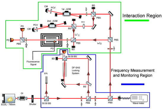
Figure 1.
Optical setup of the experiment. The setup is divided into two regions: the frequency measurement and monitoring region in blue, and the Interaction region in green, which highlights the main part of the experiment. In the figure, (ECDL) is external cavity diode laser, (DF-SAS) is Doppler free saturated absorption spectroscopy setup for locking purposes, (FPI) is a Fabry–Pérot interferometer, (OI) is an optical isolator, (BS) is a beam splitter, (PBS) is a polarizing beam splitter, () is a half-wave plate, () is a quarter-wave plate, (PCV) is a plano-convex lens, (CM) is a concave mirror, (BCV) is a biconvex lens, (BD) is a beam dump, (PD) is a photodiode, and the AOM is the Bragg cell. The two AOMs are in double pass configuration, where the first AOM shifts the frequency up, whereas the second AOM shifts the frequency down and is used for scanning.
The frequency measurement and monitoring region consists of three main parts, as can be seen in Figure 1. The first component is a Fabry–Pérot interferometer from Toptica FP100 with a Free Spectral Range of 1 GHz and a finesse of 186. The second component is made up of a Doppler-free saturated absorption spectroscopy (DF-SAS) setup, through which the desired scanning frequency and peak of Rb is chosen for use in subsequent part of the experiment. A wavemeter makes up the last part of this setup, which it is mainly used to measure the actual wavelength of the laser in vacuum and to monitor the locking property of the laser when the ECDL was locked to a given transition of Rb atom.
The incident laser beam that is directed toward the interaction region of the experiment is split via a polarizing beam splitter. The s-polarized component, which acts as the coupling beam (), is directed towards a reference cell. The atomic ensemble cell contains Rb atoms with 30 Torr Ne buffer gas. The cell is placed in a solenoid, and a small magnetic field of 250–450 mG is applied to lift the degeneracy of the Zeeman sub-levels. The whole system is then installed in a three layer -metal cylinder that has a measured magnetic shielding factor of more than .
The p-polarized component, acting as the probe beam (), is directed onto the AOM setup. This part of the setup consists of two AOMs, where the first AOM (1st-AOM in Figure 1) is placed in frequency shift up position (+1st order diffracted beam is observed), while the second AOM (2nd-AOM in Figure 1) was set up in frequency shift down configuration (−1st diffraction order is created). Both AOMs were set up in double pass configuration such that, the first order diffracted beam is retroreflected back towards the AOM, whereas the zero order beam is blocked, as seen in Figure 2. At the exit of the 1st-AOM, the laser beam has a frequency of ≃ MHz, and it is then directed onto the 2nd-AOM. With a correct voltage applied to the 2nd-AOM driver, beam is directed towards the interaction cell with a frequency that closely matches that of (i.e., ).
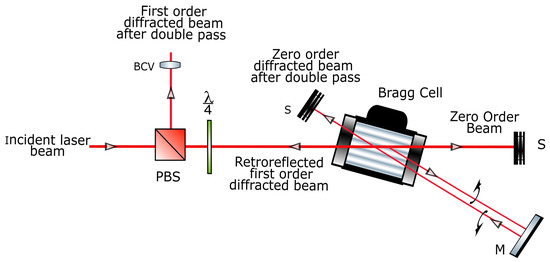
Figure 2.
Double pass configuration optical setup. The incident and retroreflected beams, using a mirror (M), are orthogonally circularly polarized due to the presence of the quarter-wave plate , and they are separated through the polarizing beam splitter (PBS). In both the incident and retroreflected beam, the zeroth order beams are blocked using a beam stop (S).
At this stage, two mutually coherent and independent beams are created, where depends solely on the properties of the ECDL, and depends on the properties of both the ECDL and the individual AOMs.
The two beams and are recombined, so that the two beams co-propagate through the vapor cell. To create a dark state that is sensitive to a magnetic field, the two beams are put through a quarter wave plate (), which creates a right and left circular polarization and , respectively, before going through the interaction cell. Upon the application of a magnetic field collinear to the direction of the beams, and excite different Zeeman transitions. Finally, when a triangular waveform is applied to the 2nd-AOM driver at low frequency and amplitude, this will produce a frequency modulation for , which is prerequisite to generate a CPT signal.
4. Results and Discussion
To create the dark state, the frequency of beam is modulated via the application of a triangular waveform to the 2nd-AOM driver using a National Instrument (NI) software and hardware (myDAQ) (a standard laboratory function generator could also be used, however the former method is chosen for reasons related to flexibility in controlling of the applied signal). This triangular waveform produces the desired modulation required for CPT, however, it creates a problem that is critical for the observation of CPT. This problem is related to the dependency of the diffraction angle and therefore the separation between the zeroth and the first order diffracted beam on the applied RF signal.
The root of the problem can be explained as follows. When a triangular waveform is applied to the AOM driver, the diffraction angle also follows this triangular signal, as it is well known there exists a direct relationship between the diffraction angle and the applied RF signal, as can be seen from Equation (1).
Here, is the diffraction angle, is the optical wavelength, is the RF frequency that depends on the voltage applied to the AOM driver, n is the refractive index of the AOM crystal (which is tellurium dioxide for the AOM used), and is the acoustic velocity.
Due to the above dependency, a variable beam steering for the first order diffracted beam is created. As a result, a periodical change in the degree of overlap between and forms. Critically, previous studies have shown broadening of the linewidth due to decreased overlap between the two beams [21,28,29]. Consequently, application of a triangular waveform creates a periodical change in the broadening of the dark resonance, which introduces artifacts to the CPT signal and ultimately a reduction in sensitivity of the magnetometer. These problems clearly defeat the purpose of creating a sensitive magnetometer based on this method and, therefore, one must avoid them.
There has been some efforts to reduce the above beam steering effect, namely in the form of a double pass configuration [30] as well as the use of fiber-optic cable [31], where the two beams are coupled together to eliminate the change in overlapping between the two beams. Although these methods reduce the beam steering effect, they introduce further complications in the form of intensity fluctuation in the modulated beam. This is because. as a result of the applied triangular signal, the coupling efficiency of the fiber cable changes periodically, as the modulated beam moves in and out of focus of the lens that is used to couple the light with the optical cable. This fluctuation in intensity creates a periodical power difference between and and, as a result, the interaction frequency between the two beams shifts due to a light shift phenomenon [20].
The periodical variation in intensity shifts the position of the CPT resonance and, as a result, a magnetometer based on this method is impractical unless these technical difficulties are overcome. This is because it cannot be determined if the shift in the resonance position is due to the intensity fluctuation or due to changes in the B-field in the vicinity of the detector.
To reduce and eliminate this change in the intensity fluctuation and the change in overlapping degree between and , an optical setup was used as shown in Figure 1 and Figure 2. The result can be seen in Figure 3, where there is no fluctuation in intensity for modulation voltage (for the driver) up to 1.6 V. This value corresponds to stability in intensity and beam steering for modulation up to 30 MHz. Furthermore, our optical setup reduces the degradation of the efficiency and the circularity of the exit beam, as no complicated optical elements that are found in other noted studies are used. It is worth noting that the result of Figure 3 is based on an optimized optical setup, whereas many investigations on the beam property, such as beam waist, steering, and divergence, were recorded and the effect of these were all measured on the CPT peak.
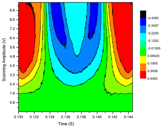
Figure 3.
Intensity fluctuation as a result of applied periodical triangular waveform to the AOM driver. The initial green region indicates no or non-detectable fluctuation in intensity for scanning amplitude up to 1.6 V. This corresponds to intensity stability for modulation up to 30 MHz in the double pass setup. When scanning amplitude (i.e., the amplitude of the triangular waveform) is increased to above 1.6 V, small variation in intensity can be detected. Above 2.4 V, a clear fluctuation in intensity can be seen in the form of the color of the contour.
It was discussed in previous sections that the CPT is of -type. This configuration is created when a small magnetic field (≈450 mG) is applied collinearly to the direction of the beams. The applied magnetic field lifts the degeneracy; as a result, multiple configurations form, as shown in Figure 4A. The ECDL was tuned to , which means is tuned to this transition. An appropriate voltage was selected for the 2nd-AOM so that, at the exit of the 2nd-AOM and in the interaction cell, has a frequency that matches ; as a result, a -type is created, as shown in Figure 4B.
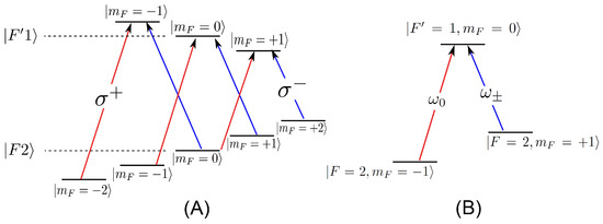
Figure 4.
In (A) multiple configurations form when a magnetic field is applied to . The frequency shift responses to the applied magnetic field of the Zeeman sub-levels are 0.70 MHz/G and −0.23 MHz/G for and energy levels, respectively. (B) is the configuration where the CPT is based in this work; is the unmodulated coupling beam, and is the modulated probe beam.
Application of a 1 V peak voltage with 0.05 V step triangular waveform to the 2nd-AOM driver results in being detuned around the transition, and, at exact zero detuning, a CPT signal was obtained as shown in Figure 5. The CPT signal was found to have a full width half maximum (FWHM) of 168 Hz at an ambient temperature of 19 °C. The dispersion like signal of the resonance peak, which is the measured first derivative of the CPT signal, was found to have a slope of 63 Hz. This corresponds to a magnetic field of 9.0 nT for the above -type CPT, (since the state has 0.7 MHz shift per G as shown in Figure 4). This is the smallest shift in frequency and hence the magnetic field that can be detected for our present setup.
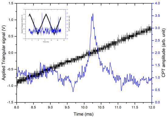
Figure 5.
CPT resonance when is detuned around . The FWHM of the resonance was calculated to be 168 Hz, which corresponds to a magnetic field of 24 nT. The inset shows the CPT signal with the scanning triangular waveform. Note that the horizontal axis is in units of milliseconds; this unit has been taken directly from the oscilloscope and, with the use of FPI, it is converted to actual frequency and thus to units of magnetic field unit.
It can be noted from the inset of Figure 5, there is a slight fluctuation in the CPT peaks. We have carried out no statistical calculations on the nature of this fluctuation due to the scope of this research, which was limited to an optimized optical setup using AOMs in the creation of a dark state magnetometer. It is the aim of future research to first increase the sensitivity of the magnetometer and also be able to record the absolute magnetic field strength, in which case such fluctuation as well as noise plays a crucial role.
Previous studies related to properties and sensitivities of CPT resonances have reported a much narrower resonance linewidth as compared to our present result [16,17]. However, our result can be improved by an order of magnitude when reduction of linewidth techniques are implemented. Examples of these techniques include optimizing the pressure of the buffer gas in the interaction cell where a CPT width of less than 50 Hz has been reported [17,28,32].
Paraffin coated cell walls also provide a narrowing of the dark resonance linewidth [33,34], while further reduction could be achieved using both buffer gas and wall coated cells [35]. It has been shown the use of alkene for wall coating can support up to atomic collisions with the wall, thus reducing the CPT width further [36]. Further steps can be taken to increase the sensitivity, such as long integration time and the use of a low intensity laser beam, which has been shown to reduce the width of the dark resonance [24,37,38,39].
5. Conclusions
In conclusion, we have shown the creation of a dark state with a narrow linewidth that is sensitive to a magnetic field using acousto-optics modulators. The optical setup was chosen to create maximum intensity stability as well as a reduction in the change of the overlapping extent between the two beams, thus avoiding dark resonance linewidth broadening.
One of the most important advantages of our present method is the creation of two beams that have identical properties with respect to each other. This is because both coupling () and probe () beams are derived from the same source outside the ECDL. As a result, the beams and therefore any subsequent interactions with the atomic ensemble are not affected by any perturbation to the ECDL, such as frequency drift and intensity fluctuation, due to environmental and mechanical factors. More correctly, any perturbation to the ECDL equally affects both beams, and therefore those perturbations will have no effect on the interaction of the beams with the atomic ensemble. The only factor that dictates and differentiates between the two beams are those imposed by the AOMs, and therefore the two beams differ only in user controlled parameters such as intensity, polarization, and frequency. Thus, this negates the use of complicated and expensive tools to temperature, current, and frequency stabilize the ECDL.
Unlike direct modulation of the injected current of the laser, modulation of the optical field based on this method keeps the linewidth of the laser as small as set by manufacturing design. Other advantages of this methods, which are related to the response and sensitivity of the magnetometer, are the choice of line of Rb, which offers a greater CPT contrast and narrower width as compared to line, and the choice of the quantum state in creating the dark resonance that has the highest gyromagnetic ratio for maximum B-field sensitivity.
Funding
This research received no external funding.
Data Availability Statement
Not applicable.
Conflicts of Interest
The author declares no conflict of interest.
Abbreviations
The following abbreviations are used in this manuscript:
| CPT | Coherent Population Trapping |
| AOM | Acoustoptic Modulator |
| ECDL | External Cavity Diode Laser |
| EIT | Electromagnetically Induced Transparency |
References
- Budker, D.; Romalis, M. Optical magnetometry. Nat. Phys. 2007, 3, 227–234. [Google Scholar] [CrossRef]
- Budker, D.; Gawlik, W.; Kimball, D.F.; Rochester, S.M.; Yashchuk, V.V.; Weis, A. Resonant nonlinear magneto-optical effects in atoms. Rev. Mod. Phys. 2002, 74, 1153–1201. [Google Scholar] [CrossRef]
- Alexandrov, E.B.; Auzinsh, M.; Budker, D.; Kimball, D.F.; Rochester, S.M.; Yashchuk, V.V. Dynamic effects in nonlinear magneto-optics of atoms and molecules. J. Opt. Soc. Am. B 2005, 22, 7–20. [Google Scholar] [CrossRef]
- Allred, J.C.; Lyman, R.N.; Kornack, T.W.; Romalis, M.V. High-sensitivity atomic magnetometer unaffected by spin-exchange relaxation. Phys. Rev. Lett. 2002, 89, 130801. [Google Scholar] [CrossRef] [PubMed]
- Budker, D.; Kimball, D.; Rochester, S.; Yashchuk, V.; Zolotorev, M. Sensitive magnetometry based on nonlinear magneto-optical rotation. Phys. Rev. A 2000, 62, 043403. [Google Scholar] [CrossRef]
- Alexandrov, E.B.; Balabas, M.V.; Vershovski, A.K.; Pazgalev, A.S. Experimental demonstration of the sensitivity of an optically pumped quantum magnetometer. Tech. Phys. 2004, 49, 779–783. [Google Scholar] [CrossRef]
- Groeger, S.; Bison, G.; Schenker, J.L.; Wynands, R.; Weis, A. A high-sensitivity laser-pumped Mx magnetometer. Eur. Phys. J. D 2006, 38, 239–247. [Google Scholar] [CrossRef]
- Kominis, I.K.; Kornack, T.W.; Allred, J.C.; Romalis, M.V. A subfemtotesla multichannel atomic magnetometer. Nature 2003, 422, 596–599. [Google Scholar] [CrossRef]
- Sheng, D.; Li, S.; Dural, N.; Romalis, M.V. Subfemtotesla scalar atomic magnetometry using multipass cells. Phys. Rev. Lett. 2013, 110, 1. [Google Scholar] [CrossRef]
- Nagel, A.; Graf, L.; Naumov, A.; Mariotti, E.; Biancalana, V.; Meschede, D.; Wynands, R. Experimental realization of coherent dark-state magnetometers. Europhys. Lett. 1998, 44, 31. [Google Scholar] [CrossRef]
- Asahi, H.; Motomura, K.; Harada, K.; Mitsunaga, M. Dark-state imaging for two-dimensional mapping of a magnetic field. Opt. Lett. 2003, 28, 1153–1155. [Google Scholar] [CrossRef]
- Gateva, S.; Alipieva, E.; Petrov, L.; Taskova, E.; Todorov, G. Single frequency coherent-population-trapping resonances for magnetic field measuremen. J. Optoelectron. Adv. Mater. 2008, 19, 98. [Google Scholar]
- Farley, D.R.; Mitrani, J.M.; Cohen, S.A. Coherent population trapping as a magnetic-field diagnostic for hydrogen plasmas. Phys. Rev. A 2012, 81, 033412. [Google Scholar] [CrossRef]
- Yang, A.; Yang, G.; Xu, Y.; Lin, Q. High contrast atomic magnetometer based on coherent population trapping. Chin. Phys. B 2014, 23, 027601. [Google Scholar] [CrossRef]
- Nakaya, Y.; Mori, H. Magnetocardiography. Clin. Phys. Physiol. Meas. 1992, 13, 191. [Google Scholar] [CrossRef]
- Arimondo, E. V coherent population trapping in laser spectroscopy. Prog. Opt. 1996, 35, 257–354. [Google Scholar]
- Wynands, R.; Nagel, A. Precision spectroscopy with coherent dark states. Appl. Phys. B. 1999, 68, 1. [Google Scholar] [CrossRef]
- Stähler, M.; Knappe, S.; Affolderbach, C.; Kemp, W.; Wynands, R. Picotesla magnetometry with coherent dark states. Europhys. Lett. 2001, 54, 323. [Google Scholar] [CrossRef]
- Shah, V.; Knappe, S.; Hollberg, L.; Kitching, J. Generation of coherent population trapping resonances with nearly 100% transmission contrast. In Proceedings of the 2007 IEEE International Frequency Control Symposium Joint with the 21st European Frequency and Time Forum, Geneva, Switzerland, 29 May–1 June 2007. [Google Scholar]
- Nagel, A.; Wynands, R.; Meschede, D. Light shift of coherent population trapping resonances. Europhys. Lett. 1999, 48, 385. [Google Scholar] [CrossRef]
- Akulshin, A.M.; Celikov, A.A.; Velichansky, V.L. Sub-natural absorption resonances on the D1 line of rubidium induced by coherent population trapping. Opt. Commun. 1991, 84, 139–143. [Google Scholar] [CrossRef]
- Marangos, J.P. Electromagnetically induced transparency. J. Mod. Opt. 1998, 45, 471–503. [Google Scholar] [CrossRef]
- Fleischhauer, M.; Imamoglu, A.; Marangos, J.P. Electromagnetically induced transparency: Optics in coherent media. Rev. Mod. Phys. 2005, 77, 63. [Google Scholar] [CrossRef]
- Wang, Y.; Zhan, M.-S.; Wang, Y.-Z. Coherent spectroscopy of the 87RbFg=1→Fe=0 closed transition. Chin. Phys. Soc. 2007, 16, 994. [Google Scholar]
- Alzetta, G.; Cartaleva, S.; Dancheva, Y.; Andreeva, C.; Gozzini, S.; Botti, L.; Rossi, A. Coherent effects on the Zeeman sublevels of hyperfine states at the D1 and D2 lines of Rb. J. Opt. B-Quantum Semiclass. Opt. 2001, 3, 181. [Google Scholar] [CrossRef]
- Stähler, M.; Wynands, R.; Knappe, S.; Kitching, J.; Hollberg, L.; Taichenachev, A.; Yudin, V. Coherent population trapping resonances in thermal 85Rb vapor: D1 versus D2 line excitation. Opt. Lett. 2002, 27, 1472–1474. [Google Scholar] [CrossRef]
- Steck, D.A. Rubidium 87 D Line Data. Available online: http://steck.us/alkalidata (accessed on 3 September 2022).
- Brandt, S.; Nagel, A.; Wynands, R.; Meschede, D. Buffer-gas-induced linewidth reduction of coherent dark resonancesto below 50 Hz. Phys. Rev. A 1997, 59, R1063. [Google Scholar] [CrossRef]
- Carvalho, P.R.S.; Araujo, L.E.E.D.; Tabosa, J.W.R. Angular dependence of an electromagnetically induced transparency resonance in a Doppler-broadened atomic vapor. Phys. Rev. A 2004, 70, 063818. [Google Scholar] [CrossRef]
- Donley, E.A.; Heavner, T.P.; Levi, F.; Tataw, M.O.; Jefferts, S.R. Double-pass acousto-optic modulator system. Rev. Sci. Instrum. 2005, 76, 063112. [Google Scholar] [CrossRef]
- Akulshin, A.; Barreiro, S.; Lezama, A. Electromagnetically induced absorption and transparency due to resonant two-field excitation of quasidegenerate levels in Rb vapor. Phys. Rev. A 1998, 57, 2996–3002. [Google Scholar] [CrossRef]
- Qu, S.; Zhang, Y.; Gu, S. Dependence of the 85Rb coherent population trapping resonance characteristic on the pressure of N2 buffer gas. Chin. Phys. B 2013, 22, 099501. [Google Scholar] [CrossRef]
- Gateva, S.; Alipieva, E.; Taskova, E.; Todorov, G. Coherent population trapping resonance structure in paraffin-coated Rb vacuum cells. In Proceedings of the 16th International School on Quantum Electronics: Laser Physics and Applications, Stockholm, Sweden, 26–30 June 2011; Volume 7747. [Google Scholar]
- Balabas, M.V.; Budker, D.; Kitching, J.; Schwindt, P.D.D.; Stalnaker, J.E. A CPT-Based 87Rb Atomic Clock Employing a Small Spherical Glass Vapor Cell. J. Opt. Soc. Am. B 2006, 23, 1001–1009. [Google Scholar] [CrossRef]
- Knappe, S.; Robinson, H.G. Double-resonance lineshapes in a cell with wall coating and buffer gas. New J. Phys. 2010, 12, 065021. [Google Scholar] [CrossRef]
- Balabas, M.V.; Karaulanov, T.; Ledbetter, M.P.; Budker, D. Polarized alkali-metal vapor with minute-long transverse spin-relaxation time. Phys. Rev. Lett. 2010, 105, 070801. [Google Scholar] [CrossRef]
- Knappe, S.; Wynands, R.; Kitching, J.; Robinson, H.G.; Hollberg, L. Characterization of coherent population-trapping resonances as atomic frequency references. J. Opt. Soc. Am. B 2001, 18, 1545–1553. [Google Scholar] [CrossRef]
- Merimaa, M.; Lindvall, T.; Tittonen, I.; Ikonen, E. All-optical atomic clock based on coherent population trapping in 85Rb. J. Opt. Soc. Am. B 2003, 20, 273–279. [Google Scholar] [CrossRef]
- Belcher, N.; Mikhailov, E.E.; Novikova, I. Atomic clocks and coherent population trapping: Experiments for undergraduate laboratories. Am. J. Phys. 2009, 77, 988–998. [Google Scholar] [CrossRef]


Publisher’s Note: MDPI stays neutral with regard to jurisdictional claims in published maps and institutional affiliations. |
© 2022 by the author. Licensee MDPI, Basel, Switzerland. This article is an open access article distributed under the terms and conditions of the Creative Commons Attribution (CC BY) license (https://creativecommons.org/licenses/by/4.0/).