Article

Numerical Simulation and Application of Transient Electromagnetic Detection Method in Mine Water-Bearing Collapse Column Based on Time-Domain Finite Element Method

1
Artificial Intelligence Research Institute, China University of Mining and Technology, Xuzhou 221116, China
2
School of Safety Engineering, China University of Mining and Technology, Xuzhou 221116, China
3
Xi’an Research Institute, China Coal Technology and Engineering Group Corp, Xi’an 710077, China
4
School of Mines, China University of Mining and Technology, Xuzhou 221116, China
5
Department of Electronic Information and Physics, Changzhi University, Changzhi 046000, China
*
Author to whom correspondence should be addressed.
Appl. Sci. 2022, 12(22), 11331; https://doi.org/10.3390/app122211331
Submission received: 13 October 2022 / Revised: 5 November 2022 / Accepted: 6 November 2022 / Published: 8 November 2022
(This article belongs to the Special Issue Mining-Induced Tremors)

Abstract

:

Highlights

  • The full-space TEM responses of different water columns were studied.
  • The concept of “geometric gravity center” effect is proposed.
  • This research has been proven in the field.

Abstract

Mine floods caused by water-bearing collapse columns are one of the most significant types of coal mine disasters in advanced detection. The transient electromagnetic method (TEM), one of the most effective means, can detect the collapse column in coal mines. However, the research on TEM used on the ground is mainly limited to half-space that does not follow underground mining conditions. This research used the whole-space TEM to detect the water-bearing collapse columns in front of the roadway. Based on the time-domain finite element method (TDFEM) and actual coal-measure strata data, this paper built the whole-space geo-electric models, summarized response characteristics, and proposed “geometric gravity center” effect. The results showed that the simulation based on TDFEM could accurately reflect the TEM response law, and the advanced detection using TEM in a mine environment was consistent with the actual situation.

1. Introduction

The development of deep resources has become an unavoidable approach for many nations around the world due to the gradual loss and depletion of superficial mineable resources [1,2,3]. However, as the mining depth of the mine increases, not only is the upper pressurized water level of the stope high, but also the water damage to the mine floor is severe [4]. Different water sources enter the mine, causing water inrush disasters because of the changes in the properties of the rock mass brought on by deep, high in-situ stress, high ground temperature, and high fluid pressure, together with the development of fault fracture zones in the strata themselves and the water-conducting fracture zones generated by mining [5,6,7]. Because of its rapidity, economy and convenience, geophysical methods, widely used to identify hidden water conduction structures such as water-bearing columns, are an effective way to prevent deep well water disasters and solve the problem of pressurized water mining [8,9,10,11]. The transient electromagnetic method (TEM), which has the advantages of high sensitivity to low-resistance bodies and can be easily constructed, is one of the primary methods for detecting water-bearing structures down in the mines [12,13,14,15]. Through the three-dimensional numerical simulation, the study of the transient electromagnetic response of water-bearing columns can not only provide a theoretical foundation for its three-dimensional inversion and data interpretation, but it can also encourage the development and use of this method, which is of great practical significance for the prevention and control of water in coal mines and safe production.
The transient electromagnetic method used in mine hydrogeological exploration is mainly divided into the ground and underground [16,17,18,19]. Affected by the narrow space of the underground tunnel, the detection devices used on the ground are different from those used underground. As shown in Figure 1, the equipment on the floor is a large ring with varying lengths of side from tens of meters to hundreds of meters, while the underground equipment is small with a side length below 3 m. In addition, the geological anomalies to be detected are underground, so the TEM used on the ground has the characteristics of a half-space response. As shown in Figure 2, the reaction of underground TEM will be affected by the whole space. Unfortunately, most current studies on transient electromagnetic detection are concentrated in the half-space. With the increase of mining depth, the distance between the ground detection device and the detection target will also increase, resulting in a decrease in the resolution of ground detection. Therefore, it is significant to study the whole space as the research object of the underground TEM data processing method.
The transient electromagnetic forward method is an effective way to study the transient electromagnetic response, mainly including the time-domain finite-difference (TDFD) method, the finite volume method, the integral equation method, and the finite element method (FEM) [20,21,22,23]. Compared with the above methods, the main advantages of the finite element method are its discrete spatial flexibility and high simulation accuracy for complex geometries [24]. In addition, with the rapid development of computer hardware, the problem of extensive computing time and memory requirements has been effectively alleviated, so the FEM is considered a common method. Kuo and Cho [25] used the FEM to simulate the TEM response of low resistivity ore bodies and discovered that the three-dimensional numerical simulation is essentially comparable with the field measured results, demonstrating the viability of the approach. Since then, Pridmore et al. [26] also carried out exploratory research on the finite element method for solving the forward problem of three-dimensional transient electromagnetic method. Sugeng [27] performed three-dimensional forward of the loop source transient electromagnetic approach based on the concept of separating the anomalous field and the background field. Through the TDFEM and tetrahedral mesh, Yin et al. studied the impact of terrain on the transient electromagnetic response [28]. Li et al. used unstructured tetrahedral meshes to study the propagation laws of short electromagnetic fields in 3D forward models of fixed and moving coils [29]. Few studies have been conducted on the numerical simulation of water-bearing collapse columns in three dimensions under full-space conditions, and their response mechanism has not been adequately explained.
Against the above background, the contributions of this study can be summarized as follows: (1) Based on the TDFEM, the whole-space transient electromagnetic responses of different water-bearing collapse columns were simulated by COMSOL. (2) By analyzing multiple sets of numerical simulation results, the “geometric gravity center” effect of the transient electromagnetic response was proposed, which guided the advanced interpretation data of the TEM. (3) The simulation and practical application indicated that the advanced detection could accurately reflect the position of the collapse column by the underground TEM.

2. Fundamentals of TEM Based on TDFEM

2.1. Time-Domain Electromagnetic Field Equation

In the application of the TEM to a mine’s multi-turn small loops, the electromagnetic field frequency is low, and the displacement current is negligible, in which case the time-domain Maxwell equation of its transient electromagnetic field can be expressed as:
× e ( r , t ) = μ ( r ) ( h ( r , t ) t + J m s ( r , t ) t )
× h ( r , t ) = σ ( r ) e ( r , t )
where h ( r , t ) and e ( r , t ) are the magnetic and electric fields at a certain point r in the whole space. σ ( r ) and μ ( r ) are the conductivity and permeability respectively. μ 0 is generally taken as the magnetic conductivity of vacuum. For a multi-turn small loops in mines,
J m S = i ω μ M
By taking the rotation of Equation (2) and substituting it into Equation (1), we can obtain the following expression:
2 h ( r , t ) σ ( r ) μ 0 h ( r , t ) t + σ ( r ) J m s ( r , t ) t = 0
Equation (4) is the equation of the magnetic field diffusion.

2.2. Vector Finite Cell Method Discretized to the Space Domain

In the calculation of the electromagnetic factors using the three-dimensional finite element method, the calculation area is generally divided into finite tetrahedron or hexahedron elements [30]. The calculation principle of these units can be found in the literature [30]. First, we set up at bedding V e unit in the area, and the four vertices of the tetrahedron are numbered i = 1, 2, 3, and 4, corresponding to the magnetic field strengths on the edge h i e ( t ) . Figure 3 shows the tetrahedral unit structure.
The magnetic field at any point P in the tetrahedral unit E can be expressed as:
h ( r , t ) = i = 1 6 N i e ( r ) h i e ( t )
where N i e ( r ) is the vector interpolation base function, and h i e ( t ) represents the magnetic field value on the ith edge in the tetrahedral element E.

2.3. Solution to a Forward Problem

2.3.1. Time Discretization

In this paper, the backward Euler method is used to discretize in the time domain using the unconditionally stable backward Euler method, which can be seen as a first-order backward differential formula. The calculation principle is as follows [31]:
y k + 1 = y k + Δ t f ( t k + 1 , y k + 1 )
In addition, considering the actual situation, the analogue time range is wide, and the current shutdown time is small. In the current shutdown time, the current and magnetic field vary rapidly, and the time step is relatively small. At other times, these parameters are relatively stable, and the time step can be appropriately longer. Therefore, this paper adopts different time steps for different stages, which can help significantly improve the computing efficiency under the premise of ensuring the calculation accuracy.

2.3.2. Boundary Condition Setting

For the calculation of transient electromagnetic fields, the commonly used approximate boundary conditions are the Neumann boundary conditions, Dirichlet boundary conditions, perfect magnetic conductor, absorption boundary conditions, and perfect matching layer (PML). Notably, since Neumann boundary conditions, Dirichlet boundary conditions, and perfect magnetic (electric) conductor all assume that the electromagnetic field value at the boundary nodes is approximately 0, the ideal state of this type of boundary condition is that the calculation region is infinite. For a 3D FEM, this type of boundary condition is often inappropriate because of the constraints of the calculation efficiency and calculation region.
Absorption boundary conditions are the best choice for simulating the propagation of electromagnetic fields in infinite space with limited computational areas and meshes. Because the complete absorption of an electromagnetic field is not realistic, an exact matching layer was proposed by Berenger to absorb electromagnetic waves that propagate outward [32]. Compared to conventional boundary conditions, a PML is equivalent to an area added outside the model that absorbs all the outgoing waves (ideally). This method is perfect for the FDTD truncation of electromagnetic waves; however, because the PML boundary conditions proposed by Berenger do not satisfy Maxwell’s equation, it is difficult to discretize finite cells. An infinite cell is a unit that tends to be infinite geometrically and is the perfect complement to the finite cell for solving infinite-domain problems [33]. Therefore, combined with the infinite element method and finite element method, and with the advantages of the PML method, an infinite-element domain is added to the outer boundary of the model, through coordinate mapping, and the magnetic field propagation is simulated to an infinite distance. Because Astley mapping infinite elements can easily handle transient problems, we used the Astley infinite meta-domain method as the boundary condition in this paper [34,35].

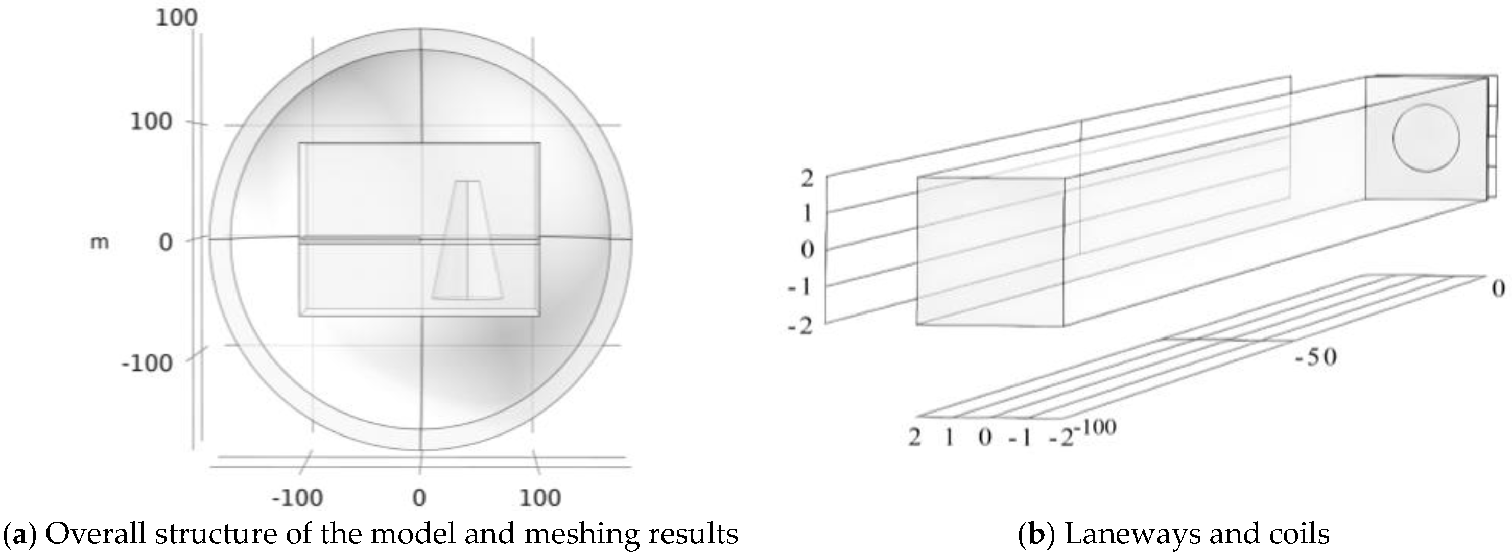
2.3.3. Non-Uniform Meshing

In this paper, the computational area is divided using unstructured tetrahedron meshes. The mesh is fine-grained in the emission backline and nearby areas to match the geometry of the area near the small return source and the rapid changes in the electromagnetic field. Due to the difference in the resistivity, the cross-interface of the difference in the semi-spatial resistivity is also refined. In other areas, because of the large geometry and small electrical differences, the tetrahedron mesh gradually expands in the direction of the calculation boundary to ensure the calculation accuracy, which significantly improves the calculation efficiency. Figure 4a,b shows the meshing effect.

2.4. Verification of Algorithm Accuracy

To verify the accuracy of the finite unit algorithm, the geoelectrical model proposed in this paper is based on a 3D sphere model considering the good symmetry of a sphere. The sphere model has a radius of 180 m, and the 18 m thick spherical shell at its outermost edge is set as the infinite-element domain. The geoelectric model is built inside, as shown in Figure 4a. The procedure is as follows: A circular coil with a radius of 1 m and a cross-sectional radius of 25 mm is placed at the center of the sphere, with a coil emission current waveform of 2 A, a shutdown time of 20 μs, a transmit backline of 60, and a receiving line of 40. Using non-uniform meshing, it is divided into 114,834 tetrahedron meshes. The analogue time starts at 0 s, and the current starts to shut down at 0.5 ms, with a shutdown time of 20 μs. The 1.5 ms analogue time ends when the current is switched off. The method of local-refinement time-step sectioning is applied, where a time step of 2 μs is used in the current shutdown process and in the range of 20 s before and after, and a time step of 20 μs is used for the rest of the duration. This can also ensure the calculation accuracy and significantly improve the computational efficiency.
Figure 5a,b compares the numerical values obtained from the full-space model and the analytical solution. The compared parameter is the induced electromotive force at the center of the coil. The full-space numerical simulation results agree the analytical solution in each period, and the relative error in the induced electromotive force is below 4.5%.

3. Numerical Simulation

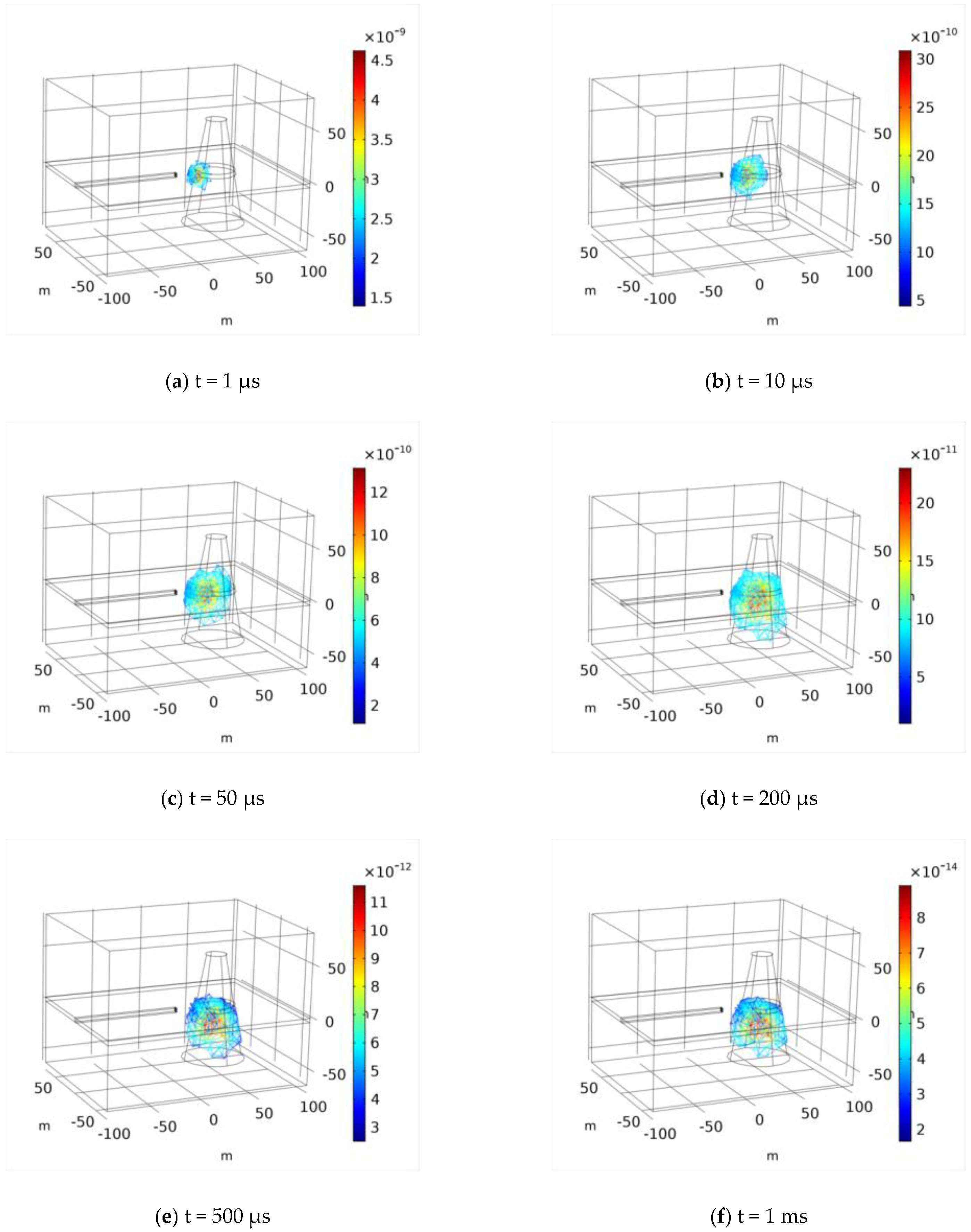
3.1. Whole-Space Transient Electromagnetic Responses of Water-Bearing Collapse Column

First, this paper establishes a sphere space modeled at 180 m and sets the 18 m thick outer boundary layer as an infinite meta-domain. A layered geoelectrical model is established, divided into three layers, representing roof, coal seam, and floor. The specific geometry and geoelectrical parameters are shown in Table 1. For the roadway model of the coal seam, we set the length of the tunnel being dug as 100 m and the roadway section dimensions as 4 m × 4 m. The interior area of the laneway is set as air, the resistivity of which is 1 × 10⁵ Ω·m. The peripheral surrounding rock resistivity of the geoelectrical model is set to 100 Ω·m. A wire device serves as the excitation source, and the coil is taken as a circular coil with a radius of 1 m, the transmitting coil is 60 turns, the receiving coil is 40 turns, the coil is placed on the tunnel head, the detecting direction is in front of the tunnel head. The coil and the tunnel head have a 25 mm interval to be consistent with the actual situation. An abnormal geologic body is placed 20 m from the tunnel head, with a resistivity of 1 Ω·m; its parameters are listed in Table 2. To study the transient electromagnetic response law of the collapse column, this paper establishes a collapse column model with an upper surface radius of 10 m, a radius of 30 m on the lower surface, a height of 100 m, a resistivity of 1 Ω·m, and placed 20 m from the excavation head. Figure 6a,b shows the specific model structure.
Figure 7a–f shows the inductive electromagnetic field in the collapse column at different times after the current is switched off. When there is no current, the far-left part of the middle of the collapse column is the first to sense the disappearance of the field and produces an inductive electromagnetic field in the area. At this point, the inductive electromagnetic field peak is approximately 4.5 × 10⁻⁹ T, and in 10 μs, the response of the electromagnetic field spreads to the inside of the collapse column and continues to spread to the center area. At 200 μs, the response spreads to the center area of the collapse column, after which it stabilizes, with only the attenuation of the electromagnetic field strength.

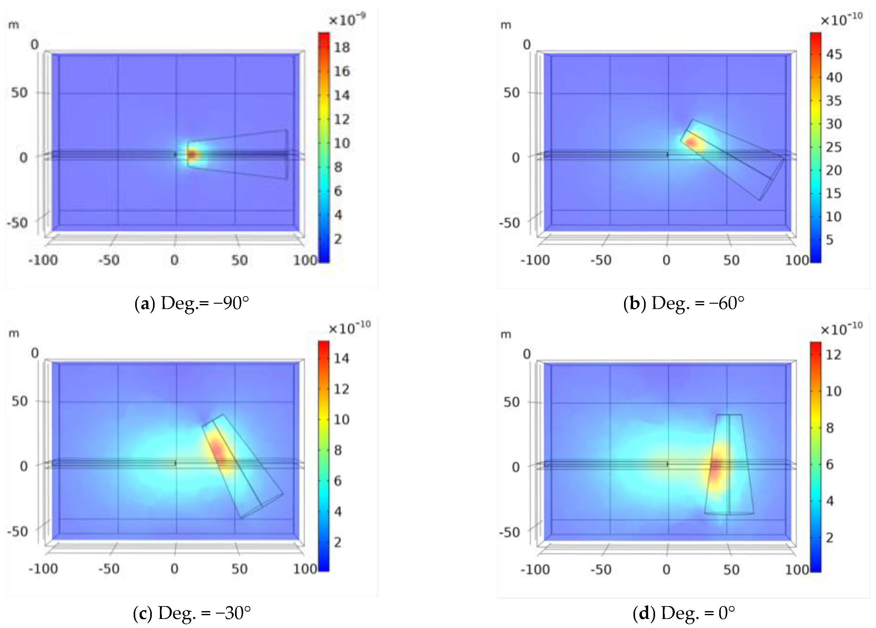
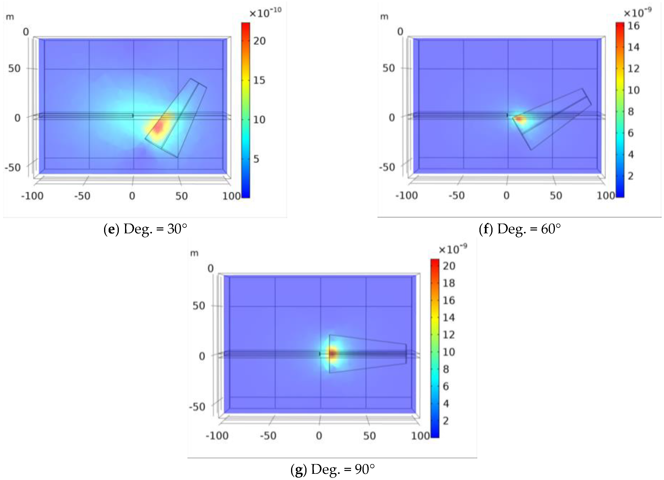
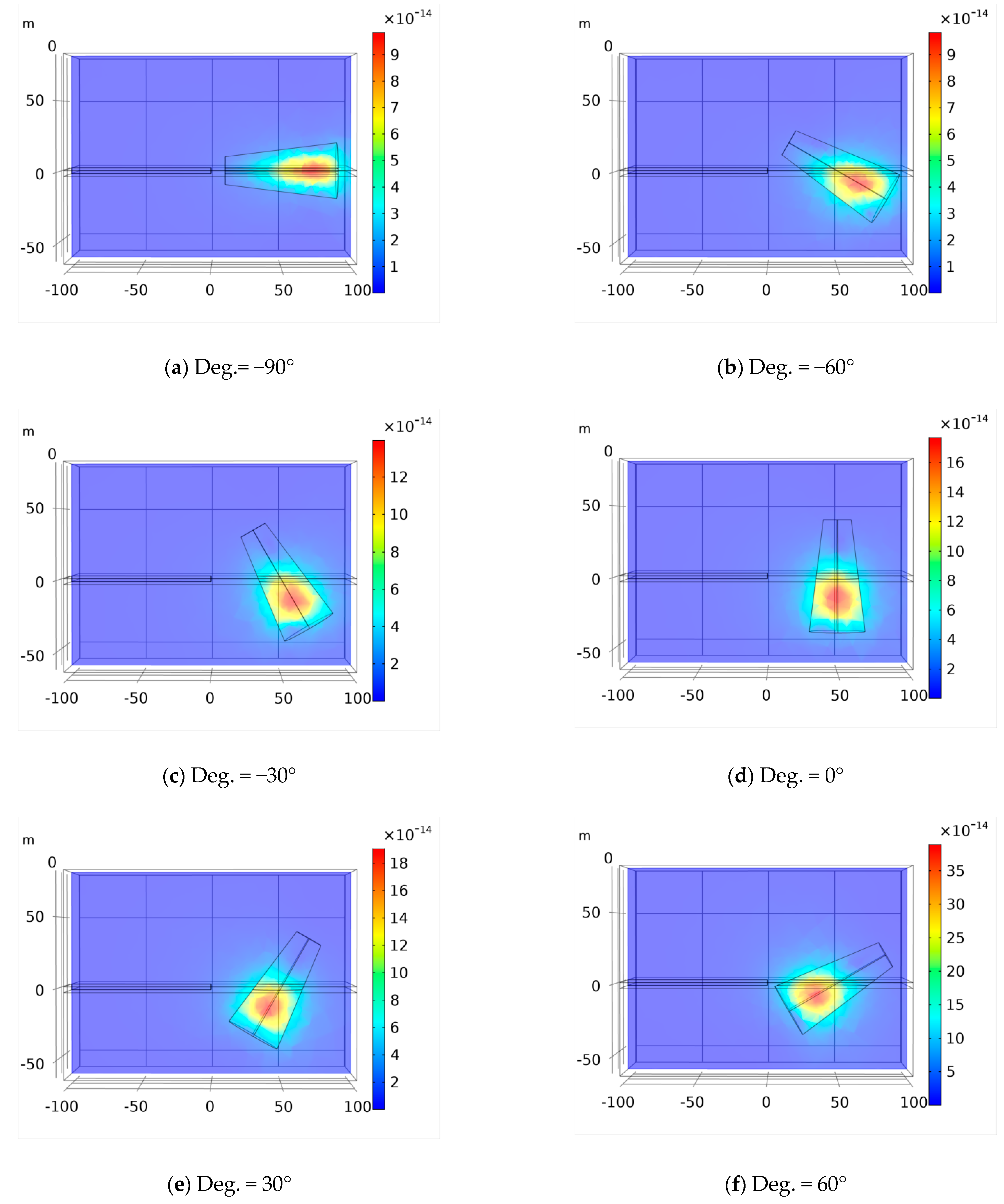
3.2. Responses of Different Inclination Collapse Column

Previous research has shown that the transient electromagnetic response is first generated by the point sensing of the abnormal body closest to the coil after being shut down and gradually migrates internally over time and eventually to the central part. Therefore, this paper proposes a “geometric gravity center” effect of the transient electromagnetic response, i.e., regardless of the morphological distribution of the low-impedance bodies, the place of the first inductive electromagnetic field is the part closest to the coil, and the final area is always concentrated near its geometric gravity center.
To verify the “geometric gravity center” effect, this section established the collapse column models with different inclination angles, including −90, −60, −30, 0, 30, 60, and 90°. In an actual geological environment, the development of the vast majority of collapse columns is vertical or similar to a vertical formation distribution. The upper surface radius of the collapse column model in each figure is 10 m. The lower surface radius is 20 m, the height is 80 m, and the apparent resistivity is 1 Ω·m.
Figure 8a–g shows the magnetic induction strength distribution of the collapse column at different angles on the xoz plane 10 μs after shutdown. After the shutdown, the area closest to the coil of the collapse column is the first to perceive the disappearance of a field, and an inductive electromagnetic field is generated in this area. The collapse column inclination is different, and the position and magnetic induction intensity of the first transient electromagnetic response is different. After a shutdown for 500 μs (Figure 9a–g), the transient electromagnetic response law in the collapse column at various angles is stabilized.
Figure 10a–c shows the decay law of the induced electromotive force at the center point of the loop of the collapse column model at different angles. Figure 10a shows that the decay rate of the induced electromotive force of each model, from large to small, follows the order: −90° > −60° > −30° > 0° > 30° > 60° > 90°. The early and late induced electromotive forces, from large to small, are shown in Figure 10, where Figure 10b and Figure 10(c) respectively show the early and late stage after switching off the current.

4. Practical Application

This part seeks to use the above-mentioned response law to direct the field detection and data interpretation of 3114 working face in Mataihao coal mine, thereby verifying the law’s accuracy. According to the three-dimensional seismic data of the mine, the DF25 fault run through 3112, 3114, and 3116 working faces, the transport roadway of 3114 working face, and the return airway of 3116 working surface crossed the fault. To find out the distribution of water-rich area of DF25 fault near the transport roadway crossheading of 3114 working face and the return airway crossheading of 3116 working face, it is necessary to carry out underground TEM advanced detection of fault water-richness.
The design height of the 3114 working face is 6 m, 31 coal is mined, the buried depth of the coal seam is about 387 m, the thickness of the coal seam is 6~7.7 m, and the average thickness is 6.53 m. The thickness of the coal seam roof is 164.07~255.13 m for Jurassic strata, and the average thickness is 187.47 m. The 3114 face coal seam has a crack-to-production ratio of around 27 times, meaning that when the working face is mined to a height of 6 m, the development height of the water-conducting fracture zone is 162 m. After the recovery of the 3114 working face, the water-conducting fracture zone developed in the Jurassic stability formation formation of the coal seam roof, and was not connected with the Cretaceous Zhidan group sandstone aquifer. The direct water filling source during the mining process of the 3114 working face is the sandstone fracture aquifer of the Yan’an Formation and Zhiluo Formation on the roof of the coal seam, the aquifer is weak in water richness, the normal water inrush of the working face is 100 m³/h, and the maximum inrush is 200 m³/h. The working surface is generally filled with low water intensity.
Figure 11 is the result of advanced detection before grouting. In the pictures, the blue-green and yellow-red regions represent the low resistivity anomaly areas (relatively rich water area) and the relatively high resistivity areas (weak water area or no water area), respectively. In the direction of roof and layered detection, the abnormal area is located on the left side of the roadway 40 m~right side 40 m, detection direction 30~50 m. After the exploration, the mine conducted drilling design and construction combined with geophysical exploration results. During the drilling construction, the water yield of No. Z2-8 borehole in 3116 return airway was the largest, reaching 66 m3/h, and the water yield of other boreholes was 1–11 m3/h. The drilling water output area is in the low resistivity anomaly area delineated by mine transient electromagnetic.
After determining the specific location of the water-bearing collapse column, multiple boreholes are arranged on the ground for grouting treatment to prevent flooding. When the grouting treatment is completed, the mine TEM was used again for detection. The detection results are shown in Figure 11. As shown in Figure 11, when there is a water-conducting structure, the resistivity value at the anomaly is reduced, and the contour distribution is distorted, deformed, or densely striped. Figure 12 showed that the isoline of apparent resistivity changes stably and uniformly without significant decrease. This showed that after grouting treatment, the collapse column and surrounding rock strata are fully integrated into the relevant electrical characteristics.

5. Discussion

Figure 7a–f show the induced electromagnetic field in the collapse column at different times after breaking the current, which is consistent with the research law obtained by Chang‘s [36] research: After the current is turned off, the induced electromagnetic field in the collapse column first appears at the position closest to the transmitting coil, and then gradually diffuses to the central area and stabilizes. By comparing Figure 8a–g in Section 3.2, each model of the magnetic induction intensity peak from large to small is: −90° = 90° > 60° > −60° > 30° > −30° > 0. When an electromagnetic induction field is generated in the collapse column after the shutdown, the minimum distance between the collapse column and the coil is different due to the difference in the collapse column inclination. The smaller the minimum distance, the greater the magnetic induction strength. In addition, comparing Figure 9a–g, it can be found that the transient electromagnetic responses of all models are finally concentrated near the geometric gravity center of the collapse column. Finally, the law of numerical simulation may lead the data processing and interpretation of the coal mine transient electromagnetic method, as shown by the real field application. The aforementioned response laws can be confirmed by other engineering practice applications in the future, and new transient electromagnetic response laws under complex settings can be researched based on TDFEM.

6. Conclusions

(1)
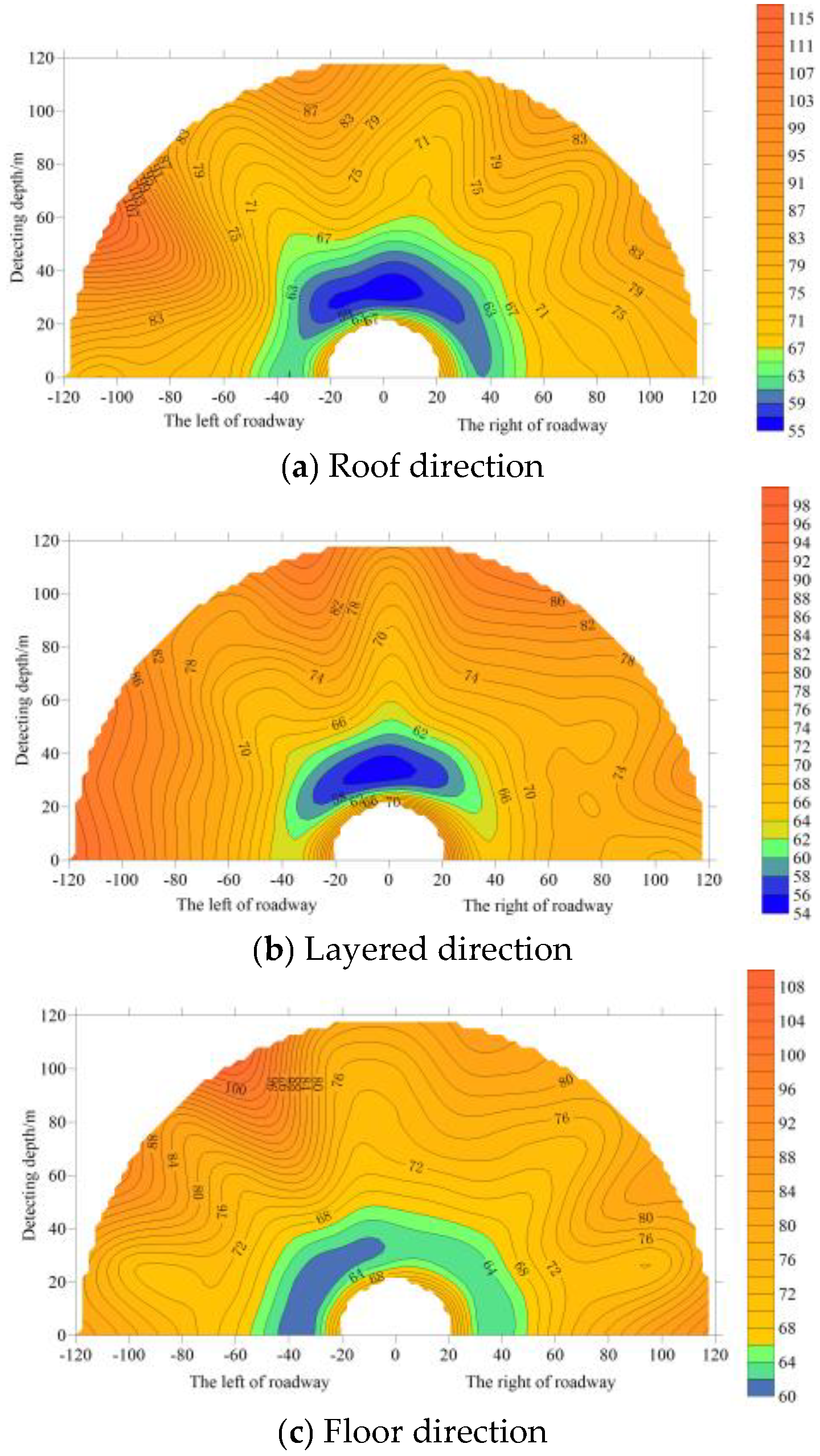
Based on the TDFEM, it is discovered that the response law of the water-bearing collapse column under full-space conditions is as follows: After the current is switched off, the induced electromagnetic field in the collapse columns first always appear at the point nearest to the transmitting coil, and then progressively diffuses to the middle area and stabilizes; The smaller the minimum distance, the greater the magnetic induction strength.
(2)
The “geometric gravity center” effect is proposed after analyzing the collapsed column model’s response characteristics at various inclination angles and discovering that all models’ transient electromagnetic responses are ultimately concentrated close to the collapsed column’s geometric gravity center.
(3)
This research can advance the fundamental theoretical understanding of mine transient electromagnetic, enhance exploration technology, and raise the degree of data processing and interpretation for mine transient electromagnetism, all of which are crucial for increasing the detection precision and effectiveness of mine transient electromagnetism and extending its range of applications.

Author Contributions

Conceptualization, C.G. and L.M.; methodology, S.C. and K.Z.; software, S.C. and K.Z.; validation, L.M., S.C. and K.Z.; writing—original draft preparation, C.G.; writing—review and editing, visualization, T.T.; supervision, T.T.; T.T.; project administration, L.M.; funding acquisition, C.G. All authors have read and agreed to the published version of the manuscript.

Funding

This research was funded by the Natural Science Foundation of Jiangsu Province grant number No. BK20221130 And The APC was funded by Changfang Guo.

Institutional Review Board Statement

Not applicable.

Informed Consent Statement

Not applicable.

Data Availability Statement

Not applicable.

Acknowledgments

We thank Yiding Chen for providing the data.

Conflicts of Interest

We declare that none of the work contained in this manuscript is published in any language or currently under consideration at any other journal, and there are no conflicts of interest to declare. All authors have contributed to, read, and approved this submitted manuscript in its current form.

References

  1. Wang, C.; Cheng, Y. Role of coal deformation energy in coal and gas outburst: A review. Fuel 2023, 332, 126019. [Google Scholar] [CrossRef]
  2. Wang, X.; Wang, E.; Liu, X.; Zhou, X. Failure mechanism of fractured rock and associated acoustic behaviors under different loading rates. Eng. Fract. Mech. 2021, 247, 107674. [Google Scholar] [CrossRef]
  3. Wang, H.; He, M.; Zhang, Z.; Zhu, J. Determination of the constant mi in the Hoek-Brown criterion of rock based on drilling parameters. Int. J. Min. Sci. Technol. 2022, 32, 747–759. [Google Scholar] [CrossRef]
  4. Zuo, J.; Wu, G.; Du, J.; Lei, B.; Li, Y. Rock Strata Failure Behavior of Deep Ordovician Limestone Aquifer and Multi-level Control Technology of Water Inrush Based on Microseismic Monitoring and Numerical Methods. Rock Mech. Rock Eng. 2022, 55, 4591–4614. [Google Scholar] [CrossRef]
  5. Yang, F.; Pang, Z.; Duan, Z. Distinguishing between faults and coal collapse columns based on sediment dating: A case study of the Huainan coal field, China. Environ. Earth Sci. 2016, 75, 959. [Google Scholar] [CrossRef]
  6. Yao, B.; Wei, J.; Wang, D.; Ma, D.; Chen, Z. Numerical study on seepage property of karst collapse columns under particle migration. CMES Comput. Model. Eng. Sci. 2013, 91, 81–100. [Google Scholar]
  7. Wang, X.; Asem, P.; Hu, C.; Labuz, J.F. Microcracking in tensile fracture of a brittle rock. Eng. Fract. Mech. 2021, 251, 107789. [Google Scholar] [CrossRef]
  8. Xue, G.-Q.; Li, X.; Gelius, L.J.; Qi, Z.-P.; Zhou, N.-N.; Chen, W.-Y. A new apparent resistivity formula for in-loop fast sounding TEM theory and application. J. Environ. Eng. Geophys. 2015, 20, 107–118. [Google Scholar] [CrossRef] [Green Version]
  9. Xue, G.-Q.; Bai, C.-Y.; Yan, S.; Greenhalgh, S.; Li, M.-f.; Zhou, N.-n. Deep sounding TEM investigation method based on a modified fixed central-loop system. J. Appl. Geophys. 2012, 76, 23–32. [Google Scholar] [CrossRef]
  10. Yin, C.; Qi, Y.; Liu, Y. 3D time-domain airborne EM modeling for an arbitrarily anisotropic earth. J. Appl. Geophys. 2016, 131, 163–178. [Google Scholar] [CrossRef]
  11. Li, X.; Liu, W.-T.; Zhi, Q.-Q.; Zhao, W. Three-dimensional joint interpretation of nuclear magnetic resonance and transient electromagnetic data. Chin. J. Geophys. 2015, 58, 2730–2744. [Google Scholar]
  12. Chen, K.; Xue, G.Q.; Chen, W.Y.; Zhou, N.N.; Li, H. Fine and Quantitative Evaluations of the Water Volumes in an Aquifer Above the Coal Seam Roof, Based on TEM. Mine Water Environ. 2019, 38, 49–59. [Google Scholar] [CrossRef]
  13. Guoqiang, X.; Jingcun, Y. New development of TEM research and application in coal mine exploration. Prog. Geophys. 2017, 32, 319–326. [Google Scholar]
  14. Li, Y. Key Technologies for Dynamic Imaging of Disaster-Causing Concealed Water Bodies in Underground Coalmines Based on Transient Electromagnetic Method. Trait. Signal 2020, 37, 301–306. [Google Scholar] [CrossRef]
  15. Lin, G.; Dong, D.; Li, X.; Fan, P. Accounting for Mine Water in Coal Mining Activities and its Spatial Characteristics in China. Mine Water Environ. 2020, 39, 150–156. [Google Scholar] [CrossRef]
  16. Jiang, Z.; Liu, L.; Liu, S.; Yue, J. Response Characteristics of Water-Bearing Goafs for Surface-to-Underground Transient Electromagnetic Method. J. Environ. Eng. Geophys. 2019, 24, 557–567. [Google Scholar] [CrossRef]
  17. Khan, M.Y.; Xue, G.-Q.; Chen, W.-Y.; Boateng, C.D. Investigation of Groundwater In-rush Zone using Petrophysical Logs and Short-offset Transient Electromagnetic (SOTEM) Data. J. Environ. Eng. Geophys. 2020, 25, 433–437. [Google Scholar] [CrossRef]
  18. Shi, X.; Zhu, S.; Zhang, W. Study on the mechanisms and prevention of water inrush events in a deeply buried high-pressure coal seam-a case study of the Chensilou Coal Mine in China. Arab. J. Geosci. 2019, 12, 19. [Google Scholar] [CrossRef]
  19. Yin, H.; Zhao, C.; Zhai, Y.; Sang, S.; Zhao, H.; Li, S.; Li, H.; Zhang, W.; Zhuang, X. Application of comprehensive support techniques to roadway tunneling in vicinity of Ordovician carbonate confined aquifers under complicated tectonic conditions. Carbonates Evaporites 2020, 35, 4. [Google Scholar] [CrossRef]
  20. Kordy, M.; Wannamaker, P.; Maris, V.; Cherkaev, E.; Hill, G. 3-D magnetotelluric inversion including topography using deformed hexahedral edge finite elements and direct solvers parallelized on SMP computers—Part I: Forward problem and parameter Jacobians. Geophys. J. Int. 2016, 204, 74–93. [Google Scholar] [CrossRef]
  21. Wang, H.; Luo, Y. Algorithm of a 2.5 dimensional finite element method for transient electromagnetic with a central loop. Chin. J. Geophys.-Chin. Ed. 2003, 46, 855–862. [Google Scholar]
  22. HuaiFeng, S.; ShangBin, L.; Yang, Y. Crank-Nicolson FDTD 3D forward modeling for the transient electromagnetic field. Chin. J. Geophys.-Chin. Ed. 2021, 64, 343–354. [Google Scholar]
  23. Yang, Y.-J.; Wang, X.-B.; Liu, X.-J.; Mi, X.-L.; Mao, L. A three-dimensional transient electromagnetic data inversion method based on a time-frequency transformation. Appl. Geophys. 2020, 17, 361–376. [Google Scholar] [CrossRef]
  24. Jin, J.-M. The Finite Element Method in Electromagnetics; John Wiley & Sons: Urbana, IL, USA, 2015. [Google Scholar]
  25. Kuo, J.T.; Cho, D.-H. Transient time-domain electromagnetics. Geophysics 1980, 45, 271–291. [Google Scholar] [CrossRef]
  26. Pridmore, D.; Hohmann, G.; Ward, S.; Sill, W. An investigation of finite-element modeling for electrical and electromagnetic data in three dimensions. Geophysics 1981, 46, 1009–1024. [Google Scholar] [CrossRef]
  27. Sugeng, F. Modeling the 3D TDEM response using the 3D full-domain finite-element method based on the hexahedral edge-element technique. Explor. Geophys. 1998, 29, 615–619. [Google Scholar] [CrossRef]
  28. Yin, C.; Qi, Y.; Liu, Y.; Cai, J. 3D time-domain airborne EM forward modeling with topography. J. Appl. Geophys. 2016, 134, 11–22. [Google Scholar] [CrossRef]
  29. Li, J.; Farquharson, C.G.; Hu, X. 3D vector finite-element electromagnetic forward modeling for large loop sources using a total-field algorithm and unstructured tetrahedral grids. Geophysics 2017, 82, E1–E16. [Google Scholar] [CrossRef]
  30. Li, J. 3D Numerical Simulation for Transient Electromagnetic Field Excited by Large Source Loop Based on Vector Finite Element Method. Ph.D. Thesis, Central South University, Changsha, China, 2011. [Google Scholar]
  31. Qi, Y. Time-domain Airborne Electromagnetic Simulation for Complex Medium. Ph.D. Thesis, Jilin University, Changchun, China, 2017. [Google Scholar]
  32. Berenger, J.P. A perfectly matched layer for the absorption of electromagnetic waves. J. Comput. Phys. 1994, 114, 185–200. [Google Scholar] [CrossRef]
  33. Luxian, L.; Songzhi, G.; Aiqin, W. The introduction and application of introduction and application. Adv. Mech. 2007, 150, 161–174. [Google Scholar]
  34. Jingtian, T.; Lincheng, Z.; Jinzhe, G.; Xiao, X. 3D frequency domain controlled source electromagnetic numerical modeling with coupled finite-infinite element method. J. Cent. South Univ. 2014, 45, 1251–1260. [Google Scholar]
  35. Blome, M.; Maurer, H.R.; Schmidt, K. Advances in three-dimensional geoelectric forward solver techniques. Geophys. J. R. Astron. Soc. 2010, 176, 740–752. [Google Scholar] [CrossRef] [Green Version]
  36. Chang, J.; Yu, J.; Su, B. Numerical simulation and application of mine TEM detection in a hidden water-bearing coal mine collapse column. J. Environ. Eng. Geophys. 2017, 22, 223–234. [Google Scholar] [CrossRef]
Figure 1. Ground TEM.
Applsci 12 11331 g001
Figure 2. Underground TEM.
Applsci 12 11331 g002
Figure 3. The structural diagram of tetrahedral unit.
Applsci 12 11331 g003
Figure 4. Results of non-uniform grid subdivision.
Applsci 12 11331 g004
Figure 5. Comparison of numerical and analytical solutions.
Applsci 12 11331 g005
Figure 6. Geoelectric model of a full-space sphere.
Applsci 12 11331 g006
Figure 7. Law of 3D electromagnetic response in full space with water-containing collapse columns.
Applsci 12 11331 g007
Figure 8. Transient electromagnetic response of 10 μs after the off-angle anomaly.
Applsci 12 11331 g008aApplsci 12 11331 g008b
Figure 9. Transient electromagnetic response of 500 μs after the shut-off of different dip angle anomalies.
Applsci 12 11331 g009aApplsci 12 11331 g009b
Figure 10. Induced electromotive force attenuation curves of different dip angle collapse columns.
Applsci 12 11331 g010
Figure 11. Detection results before grouting.
Applsci 12 11331 g011
Figure 12. Detection results after grouting.
Applsci 12 11331 g012
Table 1. Geoelectric parameters of the model.
Toward the Length (x)/mTending Length (y)/mThickness (z)/mApparent Resistivity (Ω·m)
Roof20015080100
Coal seam200150450
Floor20015060100
Table 2. Geoelectric parameters of the cylinder.
Radius of the Upper Surface/mRadius of the Lower Surface/mHeight/mApparent Resistivity (Ω·m)
Cylinder10301001
Publisher’s Note: MDPI stays neutral with regard to jurisdictional claims in published maps and institutional affiliations.

